IDA Process Diary

Harry Breeden Level 6 16021951
A note to the reader
As part time student, the design module was completed a year before IDA and therefore the brief outlines and design development within this report relate to those set out in Studio 3 design module and submitted portfolio of the 2020/21 academic year.
Topic Key
Environment, Services & Energy
Structures, Materials & Construction
Management, Practice & Law
Cultural Context
Contents
1. Design Studio Selection
Studio 3 - INHABITING THINKING MAKING
2. Where we Studied
3. Brief 01 - NARROW HOUSE - A forensic study of house and site
4. Cultural Context
Site Analysis
Site Photos
Site Constraints
Proposed Site
5. Design Process
Model Making
Light and Shadow Study
Tutorial Sessions
Material Selection
6. Environment, Services & Energy
Living Pods
Landscaping
Natural Ventilation
Zoning and Thermal Mass
Sustainability Guidance
7. Structure, Material & Construction
Reusing Foundations
Concrete and Rammed Earth
SIPs
Building Regulations
Consultant Crits
“Futurebuild”
8. Management, Practice & Law
Procurement and Contract
Funding
RIBA Plan of Work
9. Design Statements


10. Brief 02 - COURTYARD - A forensic study of habits and industry
Brief Development
Design Concept
11. Bibliography and References
2 3
4 6 14
18 34 50 62 78 86 88 98
sign Studio Selection
Studio 3 - INHABITING THINKING MAKING

STUDIO THEME


The overall studio brief developed by Sandra Denicke and Jane McAllister, is aimed at creating a discussion and brief for future living and working within urban and rural environments. These could take on different locations and socio-political qualities.
The studio ethos of INHABIT, THINK and MAKE. was encouraged to be present throughout the design process. Located in the rural location of Calabria, it is questioned where and when inhabiting, thinking and making takes place, can a mix learning method of online and on-site teaching during a pandemic, work better than a “ single campus” model, if so, what can we learn from this hybrid social-spatial model.
STUDIO - Aims and Objectives
trips to the hilltop town have proved to be invaluable in gaining knowledge of not just the architecture, but the local community, habits and ways of living.
Forming a temporary residency and being able to experience the sites in person was a great benefit to the overall design process. I was drawn to the studio aims and brief to develop a hybrid space that could provide both community and individual with a bespoke environment for industry and community.
The remote studio would also allow the formation of a small study group where we could share ideas and communicate on a daily basis.
STUDIO BRIEFS
MINI BRIEF 00


A simple exercise to investigate how design is affected by people, landscape and buildings, seen from 3 different viewpoints, near (home), middle (neighbourhood) and far ( city)
PROJECT BRIEF 01
Using the traditional Machiya House as a precedent. Through a study of habits and site, develop a small scale proposals that is centred around a house for a family and friend.

PROJECT BRIEF 02
Using the characteristics of courtyard living. Develop a proposal that aims to bring people together through industry and community to benefit local economy and social interaction.
4 5
Fig. 4 Sketching during the construction workshop. (Autumn 2020)
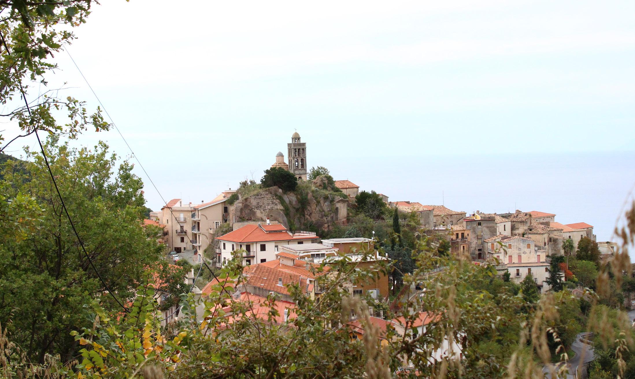
Fig. 2 View of Belmonte Calabro with the Tyrrhenian Sea in the distance.
Fig. 3. Timber works from live workshop. (Summer 2019)
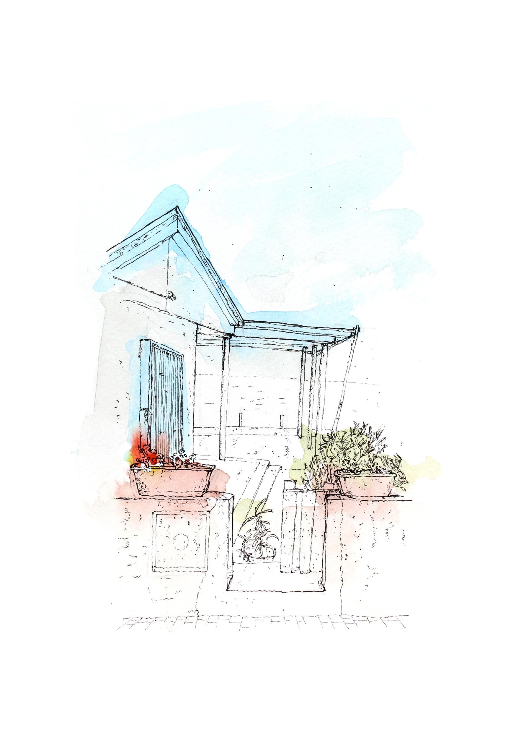
Fig. 1 Author sketch - A courtyard in Belmonte Calabro.
Where We Studied
CONTEXT - Belmonte Calabro Our Temporary Home
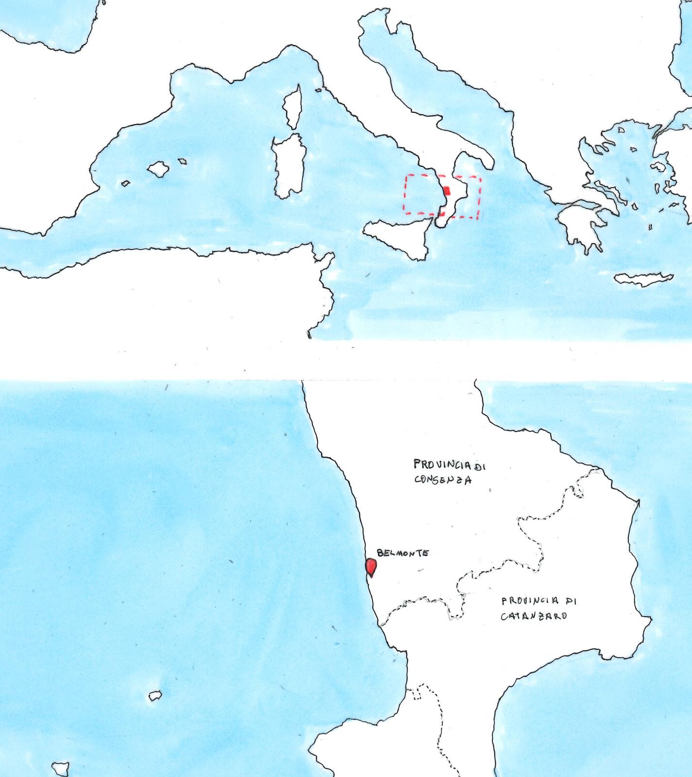
Belmonte Calabro is located on the South West coast of Italy, in the province of Cosenza. A small hilltop town bound by the Tyrrhenian sea to the west and mountainous valleys to the east.
Having participated in 2 Mudchute workshops, a summer workshop and a field-trip, these gave me the opportunity to get to know the local people, traditions and culture. Engaging in social events such as the wine festival in winter and the construction workshops during the summer months, they were all rich experiences, that very much helped throughout the development of this design project.
Tougher times led to many events being cancelled and in the midst of all the chaos of a pandemic, a group of students including myself had the opportunity to temporarily relocate to the stoned lined alleyways of Belmonte and create a small design studio that allowed us to communicate, experience and share our design thoughts 1 on 1.
The ongoing pandemic affected the entire world, but Italy in particular experienced one of the highest death tolls in the world, this lead to a dramatic change in the way people work, live and socialise, seeing an increase in remote and home working and reduced social activities.
The aim of the project was to begin to investigate and develop a program that would help the towns growth for community and business.
RIBA PLAN OF WORK


Understanding and interpreting the project brief is import to ensure the clients outcomes can be delivered. In the RIBA plan of work this would coincide with Stage 1 “Preparation and Brief”.

6 7
Fig. 5 Location of La Marina in the South of Italy
CONTEXT - Sketching In Belmonte
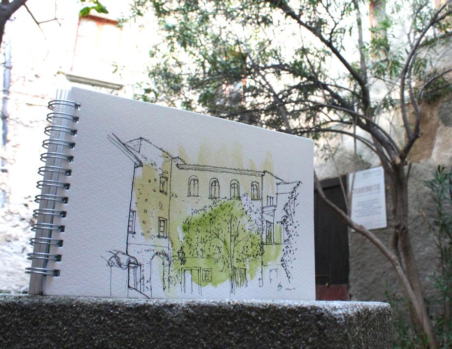
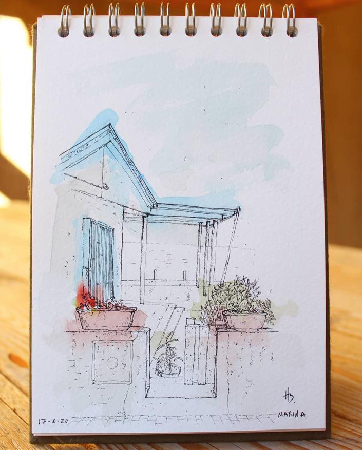


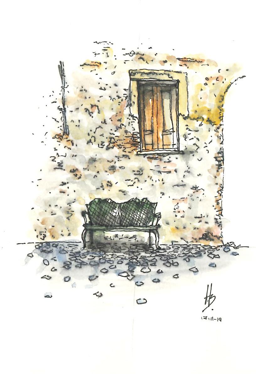
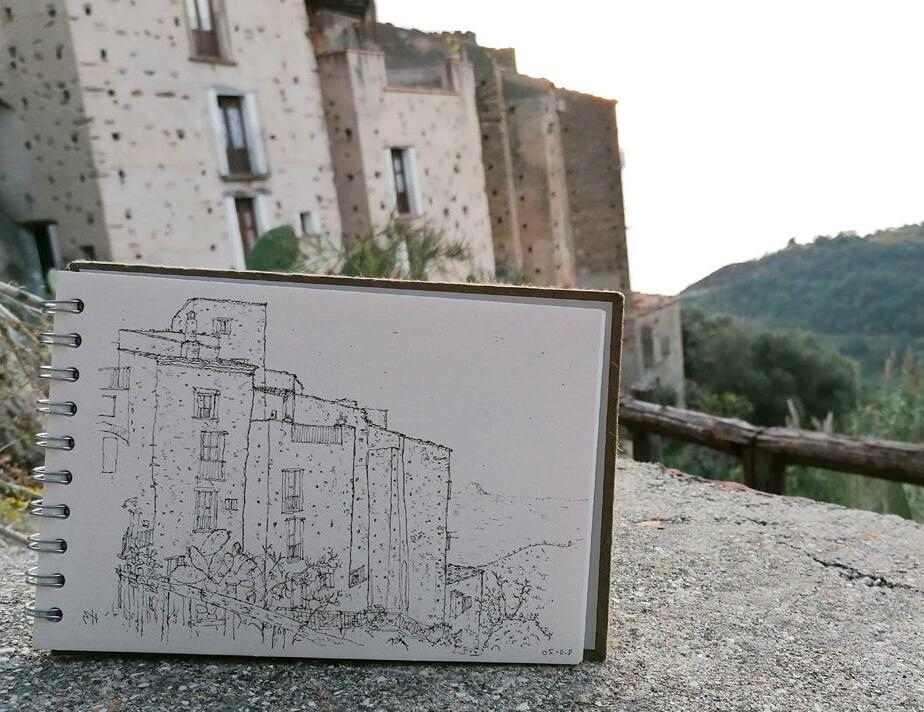
During the stay in Belmonte Calabro and after many walks down to La Marina, I found many opportunities to sketch my surroundings. This was a way of getting to know the architectural vernacular of the area, identifying textures, patterns and shadows and relating this back into my sketchbook. Here a selection of key sketches that provide an overall view of the atmosphere of the hilltop and beach front towns.

8 9
1. A courtyard in the centre of the Old Town of Belmonte Calabro.
2. A small alleyway in the Old Town of Belmonte Calabro.
3. Row of houses looking towards the Sea.
4. An abandoned doorway in the Palazzo Rivellino.
5. Local church “Chiesa S. Pasquale Bylon e S. Rosa”.
6. A beach side restaurant in La Marina.
1.
3.
5.
4.
6.
2.
4.
6.
5.
3.
1.
2.
During our stay in Belmonte Calabro we had the opportunity to experience how the locals lived, worked and relaxed. The diagram above was created to show the different spaces within the town that became part of our day-to-day living during our temporary relocation.


10 11
CONTEXT - The Belmondo Experience
During our temporary residency in Belmonte we had the opportunity to form our own studio in a local community building known as the CASA. This space is an ongoing live regeneration project led by La Rivoluzzione delle Seppie with help of locals and refugees.
The project has been live for many years and plays host to a number of live workshops throughout the year. With the help of local refugees, visiting students and locals this new hub plays host to a number of activities alongside the university and local organisations, and has become known as Belmondo.

Having participated in many activities such as the Technology “Mudchute Workshops”, summer live projects and local wine festivals, these experiences have proven invaluable to show the importance of community projects.
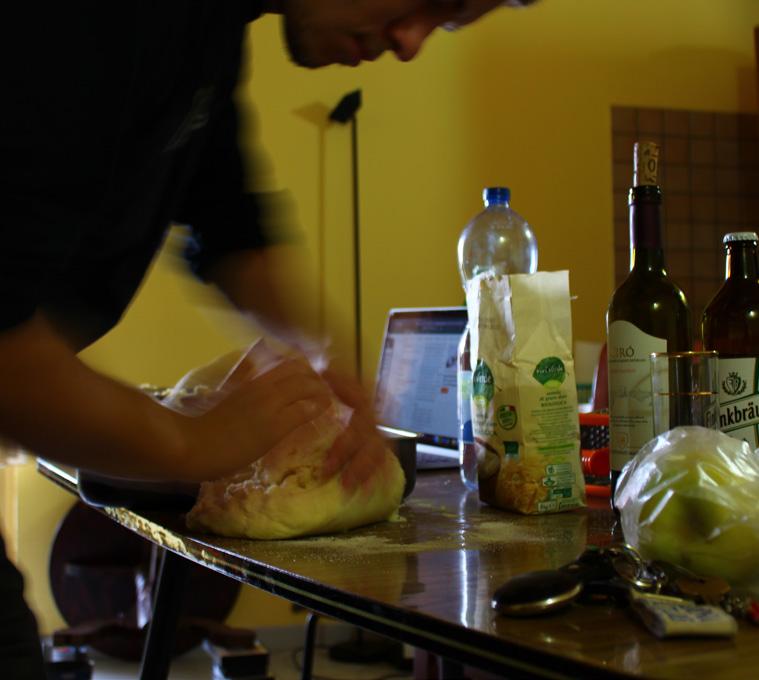
Our new temporary home in Belmonte, gave us opportunity to experience not just the local cuisine and tendencies, but also those of our fellow friends and students. Living, eating and studying together taught us the importance of conviviality, how to work as a group and how we could balance social life with study life. We were experiencing our own hybrid living which allowed us to draw from real onsite experience and interpose this into our proposed design projects.
CONTEXT - Mini Brief 00


MINI BRIEF 00 - ORIENTATION
Prior to the first brief, we were given a mini brief that would serve as an orientation exercises. The formation of a remote studio in Belmonte meant we were suddenly submerged into a new temporary HOME, NEIGHBOURHOOD AND TOWN.

TASK
Through a collection of images, sketches and ideas we had to form a number of small collages that depicted our own vision for our temporary relocation.

Collage of HOME
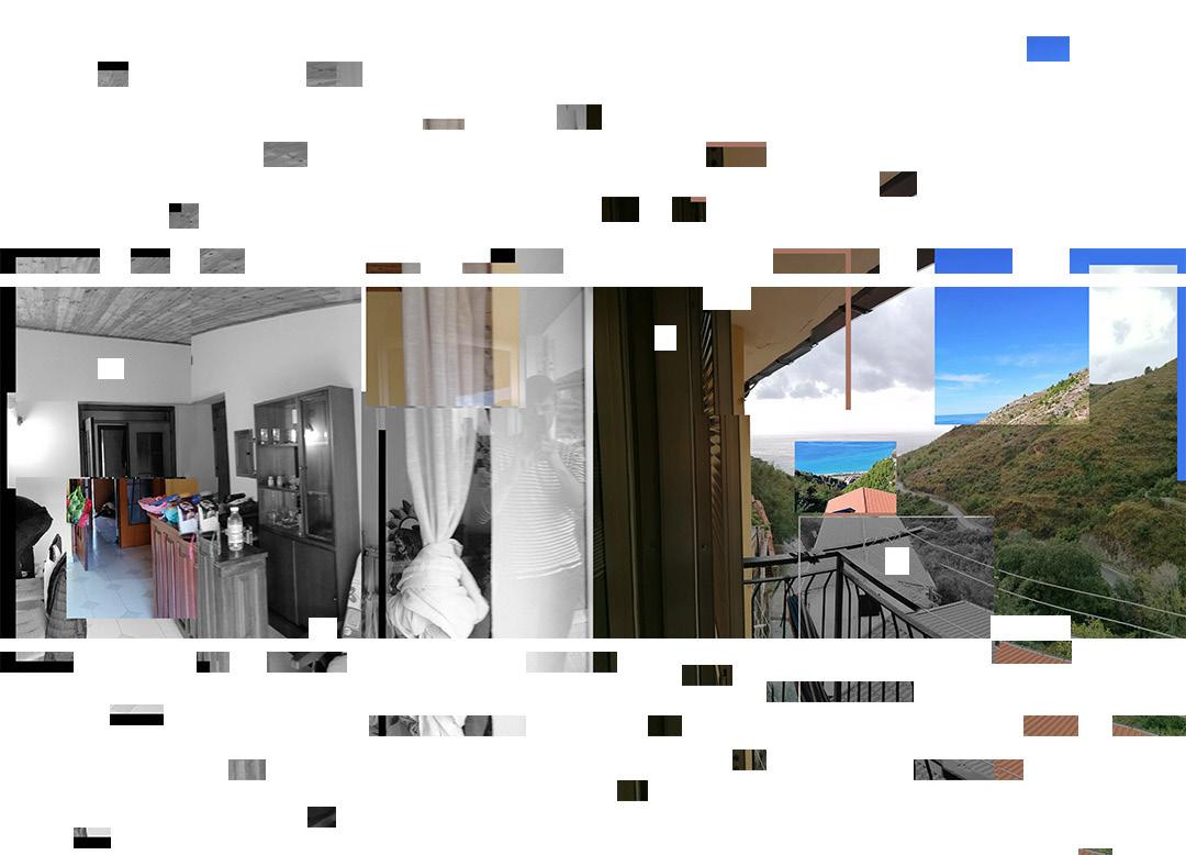
Our temporary relocation meant a new home had to be formed. A local cafe owner named Suzy leased out apartments that are completely traditional in style and allow some of the best views down to the coasts and La Marina. The use of a panoramic collage aims to show the viewpoint from inside to out.

Collage of NEIGHBOURHOOD
Many of the great moments experienced in Belmonte are after dusk. To start with the amazing sunsets and into the night, working from candle light, and finishing off with a walk back through the dimly lit alleyways. This collages aims to portray the unique low light conditions one experiences in the town.
12 13
Figure 7. Living and cooking together provided us with a sense of conviviality and communal living.
Figure 6. Known as the “Casa” the building was transformed into a temporary studio during our stay.
Suzy Local caffe owner and our temporary landlord for our stay
Angelo Local bar owner.
Brief 01 PRECEDENT - Choosing a Narrow House

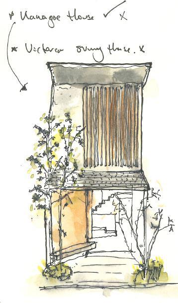
A tool-kit provided in the brief was to be used during the first project and form part of the research criteria and selection of a precedent “Machiya House”:
Tool-kit
1. Investigate small scale and spatial attitudes to living closely with friends and family.
2. Forensic study of 4.8m wide allocated strips of land.

3. Explore the possibilities of timber frame.
What is a Machiya House?
Traditionally of timber construction, they originate from Kyoto, Japan. Featuring a long and narrow plan their layouts and floors are set out to maximise the usable area as much as possible. These slim buildings are most commonly found in town house settings, between existing buildings, an therefore have inherited the term “Narrow House”.
Due to their form, in order to maximise natural daylight and ventilation, these buildings feature large openings on the front and rear elevations, in combination with open plan layouts and central voids.
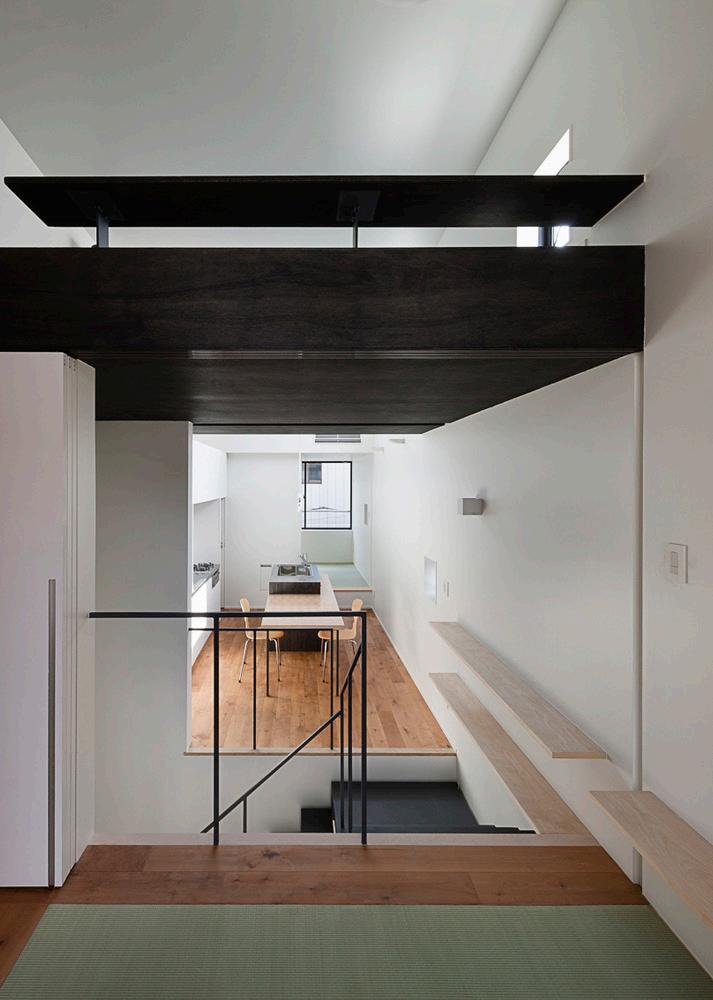
Precedent 1 - Kawagoe House
Location: Japan
Architects: K+S Architects
Features of interest:
The open floor layout has been designed so that the internal spaces face the street, allowing inhabitants to interact with passers-by. Individual rooms can be formed by movable partitions and create separation from communal spaces.
- Long views through the house.
- Uses traditional Japanese design methodologies.


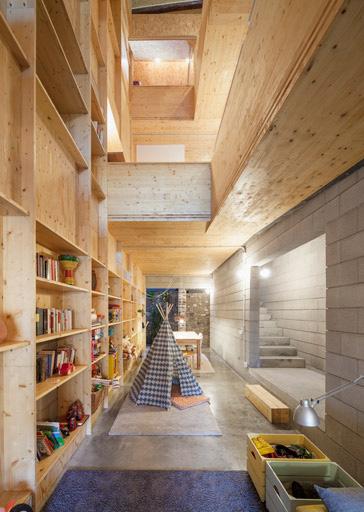
Precedent 2 - 176 House E+M
Location: Sant Cugat del Valles
Architects: Josep Ferrando
Features of interest:
The design has been developed by using a methodology called Raumplan, the interior is simply divided into interconnected multi-level spaces according to importance. Separate timber pods allow for private spaces away from the open plan design.

- Mix of hard materials (concrete) and soft materials (timber).
- Cross views across all floor plates.
14 15
1:50 0 5 0.5 1 1.5 2 3 4 Ground Floor
Figure 8. Long and narrow floor plan of 176 House E+M
Figure 9. Internal View from front to back of Kawagoe House.
Figure 10. Internal void and cross plan views.
PRECEDENT - Important Features of the Design
After further research of the precedence was the preferred model, the following design features were of interest to take forward and develop the proposed building:
- Separation of communal and private spaces with the use of timber pods. (Figure 3)

- A space designated for circulation down one side of the building, leaving the living accommodation to make use of the rest of the space. (Figure 4)
- Open plan layout, uses influence of “Raumplan” design technique, along with a central open void to allow views between floor levels. (Figure 5)
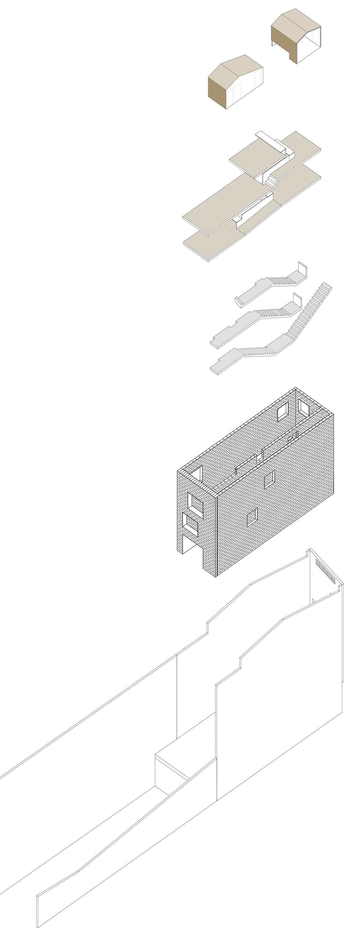
- New house is constructed within the walls of an existing house, making use of the existing structure and incorporating this into the new layout.


RESEARCH
What is a “Raumplan”?
A spatial planning concept developed by architect Adolf Loos in 1920s, whereby a buildings interior is divided into interconnected multi-level spaces according to importance. No Floor plans - Just spaces.
2. Open Floor Plates
3. Circulation Area
4. New Building
5. Existing Shell

16 17
14/10/2020
1. Timber Pods
2.
3.
4.
5.
1.
Figure 11. Timber pods Figure 12. Divided living Figure 13. Open plan layout
Sketch 2. Timber pods are pushed up against as single spine wall.
Figure 14. Exploded view of precedent building
The site location for the project is in an area of Belmonte known as, La Marina located to the west of Belmonte Calabro, at the shores of the Tyrrhenian sea. Characterized by the typical Mediterranean climate. We were allocated a portion of land that was divided into 4.8 x 350m strips. After picking a strip, based on visiting the site and undertaking surveys, we moved on to develop our proposals alongside the adjacent strips, in collaboration to form a cluster of proposals for a future vision of La Marina.
TASK


Choose a single strip, and carry out a measured and photographic survey, to begin exploring materiality and current conditions of the existing site. Marina



13/10/2020
SITE ANALYSIS - Site Allocation in La Marina
di Belmonte
Calabro
Strip
Casa PedestrianRoute VehicleRoute
La Marina
Belmonte
Proposed
The
aka
SITE ANALYSIS - Data Collecting
CLIMATE CONDITIONS


The Marina experiences a warm and temperate climate with an average temperature of 15 °C.

Wind - The prevailing wind to the Marina is from a Westerly direction, a sea breeze created from the Tyrrhenian Sea. From the East the large mountains provided a good degree of protection.

Sun - Rises and sets from East to West with long casting shadows at early and late hours of the day.
Rainfall - The Marina receives the most rainfall at the latter and earlier parts of the year, most intensely from December to February. Avrg yearly of 982mm
DEMOGRAPHICS
The average population age between the Marina and Belmonte Calabro is 48 years old. Due to an ever increasing number of the younger community moving away to larger cities, the average age is a lot higher than the national average. In recent years the town as seen an increase in migration from North Africa that reside mostly in the neighbouring town of Amantea.
ARCHITECTURE

The built forms along the Marina are varied in style, use and age. Most of the living accommodation is found in apartment blocks, alongside older historic building such as the Palazzo Rivellino and the church that add to the rich history of the small sea side town. There is also a mix of commerce, from residents setting up temporary garage shops selling local produce, to the large industries such as the Colavolpe fig factory. Viewed from above, the town is strictly divided by major transport routes of road and rail.


20 21
1.
2.
3.
1. Palazzo Rivellino
A 16th century fortress used as defence against sea enemies. Now owned by locals with a restaurant and apartments.
2. Chiesa S. Pasquale Bylon e S. Rosa
Built in 1908 by one of the largest families that owned La Marina, the Del Giudice family.
3. Apartment Housing.
This row of houses has been constructed at first floor level, accessed via staircases. Due to the likelihood of flooding in the area shops/garages are placed on a sacrificial ground floor.
4.
4. Colavolpe Fig Factory
This family run business has been producing sweet figs since 1910. Its products have become internationally recognised and exported. And is now one of the largest industries in the area.
SITE ANALYSIS - Site Surveying and Photographic Collages
In small groups we set out to survey the allocated strips in La Marina. Once we had identified our preferred sites for development, each group started to collect and record the current site conditions, using photographs, sketches, interviews with locals and producing measured surveys to accurately gather all the information needed.
PROPOSED SITE


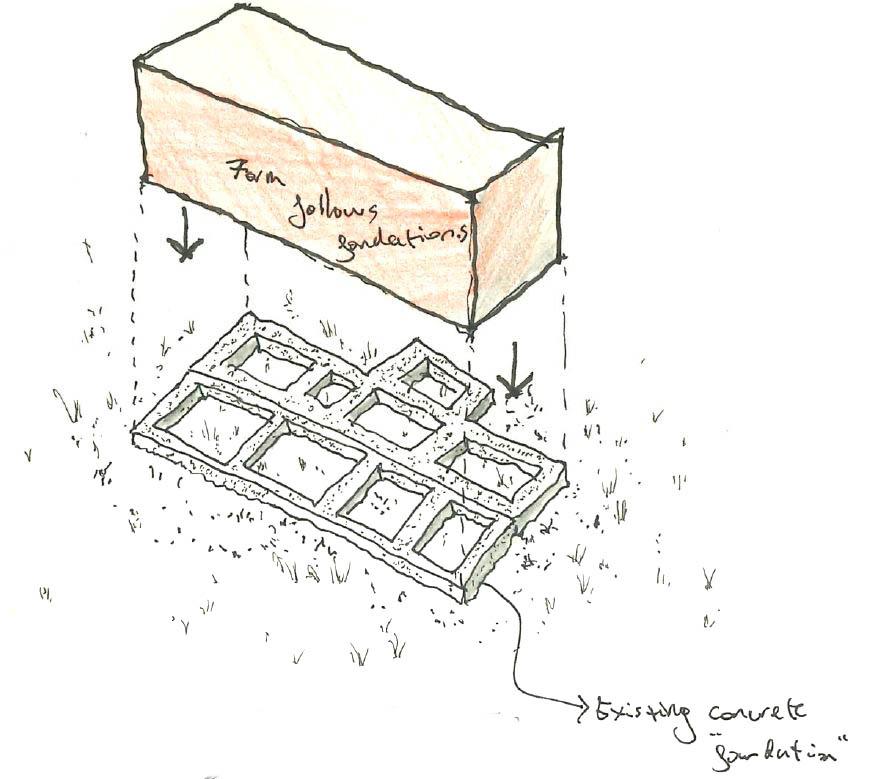
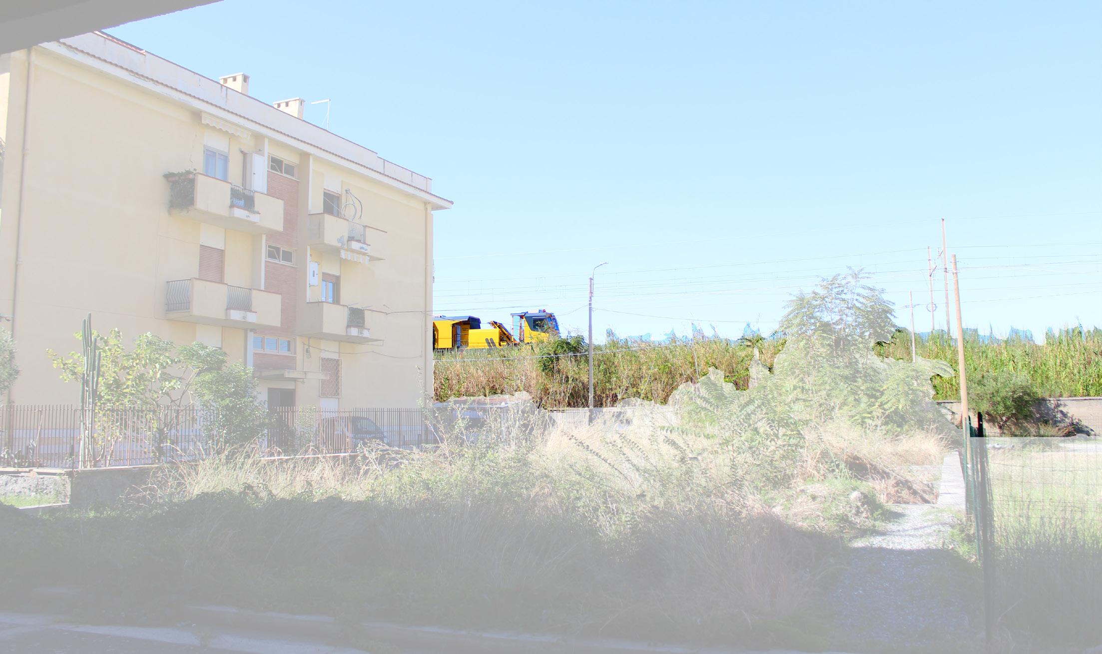
The chosen area for the proposal is located between to residential blocks to the North and South, a railway to the West and motorway to the East. Overgrown with plants, it features the reminance of concrete foundations, that were once destined for another residential block.
Immediately the initial intentions were to utilise the existing concrete foundations into the future proposal.


SEISMIC ACTIVITY
Most of Italy is located in a zone prone to earthquake activity, in particular the Southern regions feature frequent seismic activity. During the design of the primary structure and materials selection, consideration of this site condition will need to be taken.
22 23
15/10/2020
Figure 15. Existing site location plan
Proposed Site
Sketch 3. Proposal to follow the layout of foundations.
Site Photos


24 25
Figure 16. View of proposed site towards railway - Looking West
Figure 18. View of proposed site towards motorway - Looking East
Figure 17. Existing foundations
Figure 19. Main site entrance alongside the railway
Site Context and surrounding buildings

The site is surrounded by a mixture of buildings from different eras and for different uses:
The Rivellino:
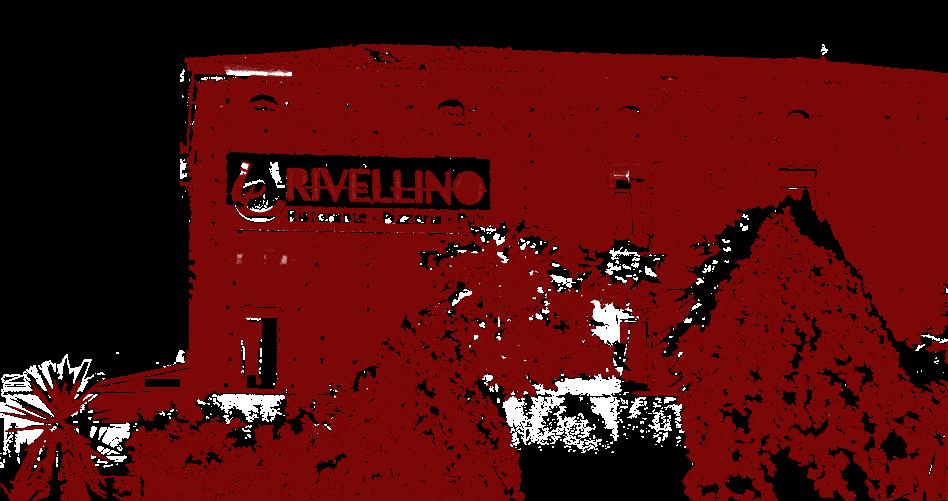


A historic building that is the largest in the Marina. Used as fortress in the 16th century to provide shelter to soldiers battling against enemy pirates. Now used as a restaurant with apartments and small shops. A local landmark.
Pischeria il Faro:
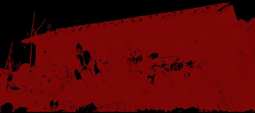
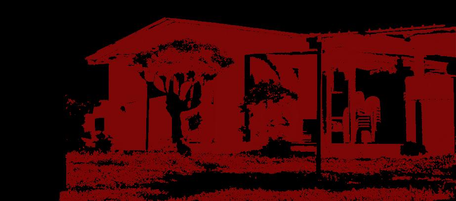
Owned by a local family, this fish shop sells the daily catch just minutes from the sea it came from.
Residential Apartments:

Located to the north and south of the site, this flats are inhabited by mostly an older generation, but with a large majority unused and empty.
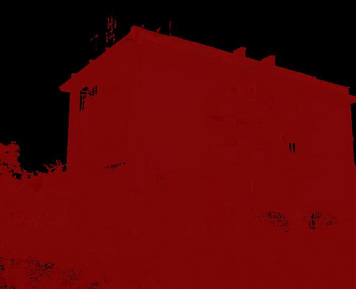
Ex-Railway Service Building:
A building that was used by local railway workers, carrying out maintenance on the tracks and signalling trains transiting through the town.
Beachfront Bar:
A local restaurant located right at the waters edge, normally open during the hot summer months.
26 THYRRENIAN
SEA
3. Residential Apartments
4. Ex- Railway Service Building
1. Ristorante Rivellino da Paolo
2. Pescheria il Faro
5. Beachfront Bar
f.12 f.10 f.9 f.11
SITE ANALYSIS - Material Collage
With the precedent building selected and first site visit completed, a material collage was created to understand and collate the materials into one view. The collage helped to see the combination of existing raw materials, such as local stone, alongside manufactured materials like concrete. This provided a canvas for selecting proposed materials and combining the different textures.

Key materials and textures:

- Cast concrete panels
- Timber lining to walls.
- Re-claimed natural stone.
- Cast in-situ concrete.

SITE ANALYSIS - Local transportation network


Being able to incorporate local materials into the design proposals was crucial, during the research stage it was clear that an analysis of the current transportation methods in La Marina was needed.
The study was very revealing and showed a great number of active and possible transport networks.
A list and route diagram was produced to show all the possibly transport routes, this helped pick and choose the most appropriate depending on the materials required. Importantly, major rail and road routes connecting the North and South of the country pass in very close proximity to the site with a local station in the Marina.
• Distance to provincial capitals:
- Cosenza 53km
- Vibo Valentia 75km
- Catanzaro. 72km
• Nearest Airport:
1h 3min 1h 5min 1h 2min
- Lamezia Terme Aeroporto 48km 50 min
• Nearest Train Station:
- Amantea 5km
- Paola 21km
• Nearest Port:


6min 21min
- Porto Turistico di Amantea 20km 29min
28 29
1.
3.
5.
2.
4.
6. On-site
2. Re-claimed traditional timber door.
3. Re-claimed stone.
4. Re-claimed traditional timber windows.
6. Cast concrete panels.
Precedent
1. Concrete block wall.
5. Plywood lining.
Material collage combinig precedent + on site materiality.
FLOOD RISK ASSESSMENT


Advice from local environmental specialist provided us with vital flood risk information. There is minimal risk to flooding during most of the year but during winter months, water proceeding from the high mountains can cause an issue in the lower level Marina.
As visible on the plan, the proposed site is not directly affected by flood risk but being in close proximity, anti-flood measures must be considered.
Flood zone areas
30 31
Pedestrian route between Belmonte Calabro and Marina . Vehicle route between Belmonte Calabro and Marina.
Proposed strip for development.
Regional Railway.
SS18 Tirrena Inferiore. (Motorway)
Belmonte Calabro
Monumento Michele Bianchi
Building expansion along coastline.
Marina Belmonte South-Bound
South-Bound Amantea - 6km
Catanzaro - 71km
Lamezia Terme - 48km
North-Bound Paola - 25km
Cosenza - 55km
Naples - 354 km
PROPOSED SITE - Axonometric Massing Study
An existing axonometric drawing of the site was produced to to overlay the precedent (1) and compare the proportions and overall dimensions, between the site and building.

A deliberate constraint was set before moving forward with the proposal, any new walls were to follow the layout of the current foundations (2) to re-purpose these and avoid the necessity of creating new foundations, leading to a number of environmental and material benefits, such as:
- According to one of the worlds leading sustainability institutes, Chatham House, around 8% of the worlds C0 2 comes from cement production. By re-using the foundations it reduces the production of Portland cement required in the construction of new foundations.

- Savings on materials usage include the steel reinforcement bars used in foundations, this also avoids the need to remove ground material from site to make way for new foundations.
Further research into the viability of reusing the foundations and the necessary investigations that need to take place, can be found under Chapter 5 “Structures, Materials and Construction”
HISTORY OF FOUNDATIONS

Further research into the local history of the site it was discovered that the foundations were constructed in preparation for an additional block of apartments to be built.

32 33
1. 2.
Design Process
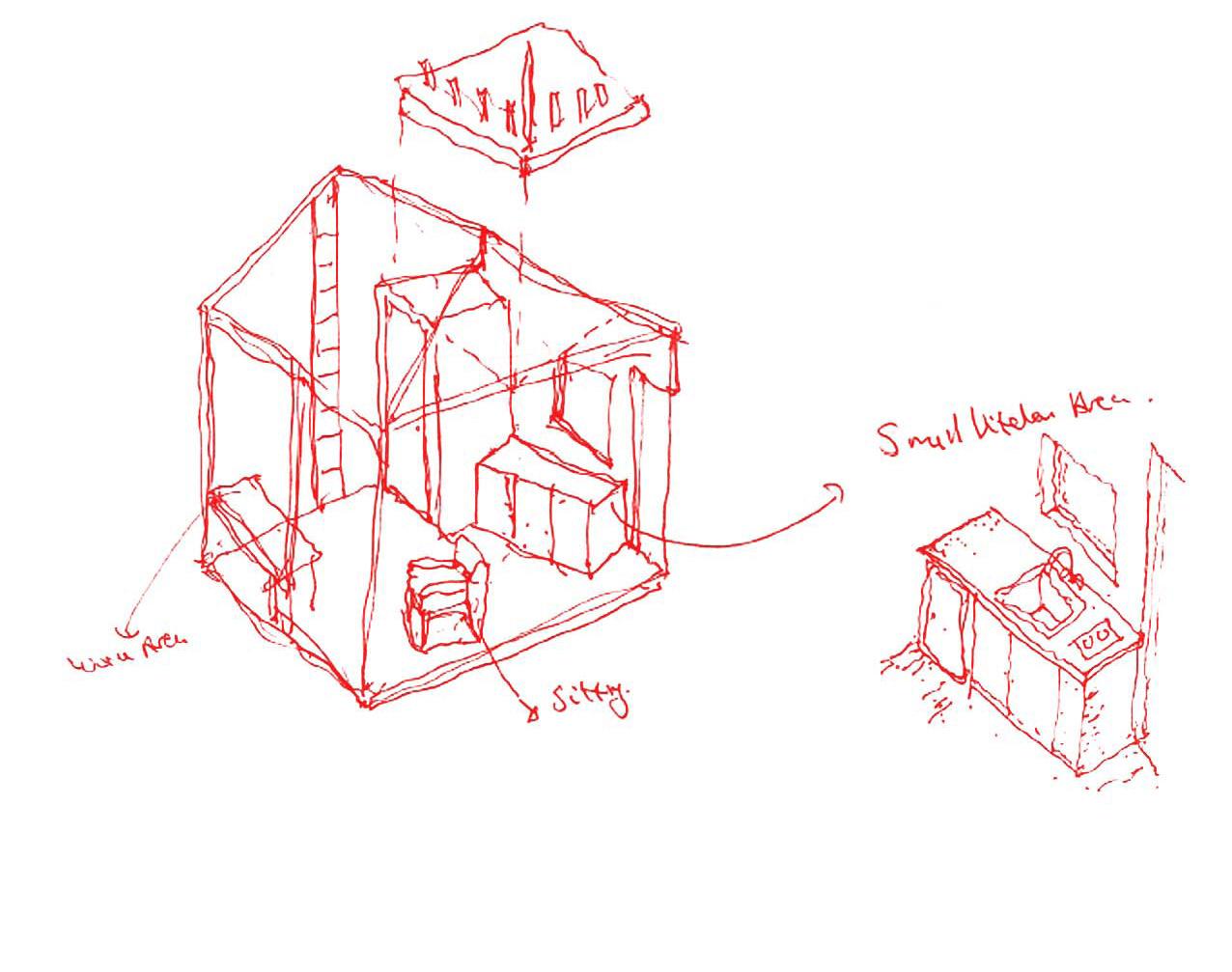
PROPOSED DESIGN - Concept Design Study of Building Elements.
The concept design begun by selecting a number of features from the site and precedent building and developing these through a series of sketch iterations. Gradually brought together to form the overall proposed building. The sketch process is personally the most efficient way to investigate many design routes and options. And thereafter once a clear design is in place it can be further developed using CAD software.

Key elements that were investigated through sketch iterations are:


- Internal Living pods positioning.
- Internal Living pod plans

- External solar shading
- Junction and material detailing

RIBA PLAN OF WORK
Preparing architectural concept design and undertake reviews with the client. In the RIBA plan of work this would coincide with “Stage 2 Concept Design”
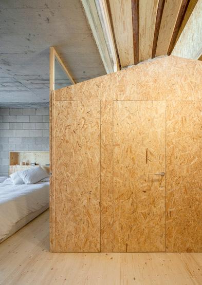
The timber pods used in the precedent building formed the central starting point for the new proposed building. Individual pods that could provide all the living requirements, in a self contained habitable space, also adaptable to a persons working needs.
The separation of circulation and habitable space also defined the layout of the building. A communal corridor down one side of the building provides stepped access to the self contained pods.
RESEARCH
SIPs living pods. Structural Insulated panels are a composite sandwich panel that is manufactured off site and then quickly assembled on site. They provide high thermal efficiency and sound absorption, reduce waste and are inherently strong.
34 35
Sketch 4. Analysis of timber pods sizing and allocation within the building.
Sketch 5. Separation of circulation and living areas. Potential workshops to take place
PROPOSED DESIGN - Model Making


A simple massing model at 1:50 scale was constructed using timber blocks and card, this was then used to analyse the internal conditions of the space and how the location of windows, doors and the pods would affect the conditions of light and shadow.
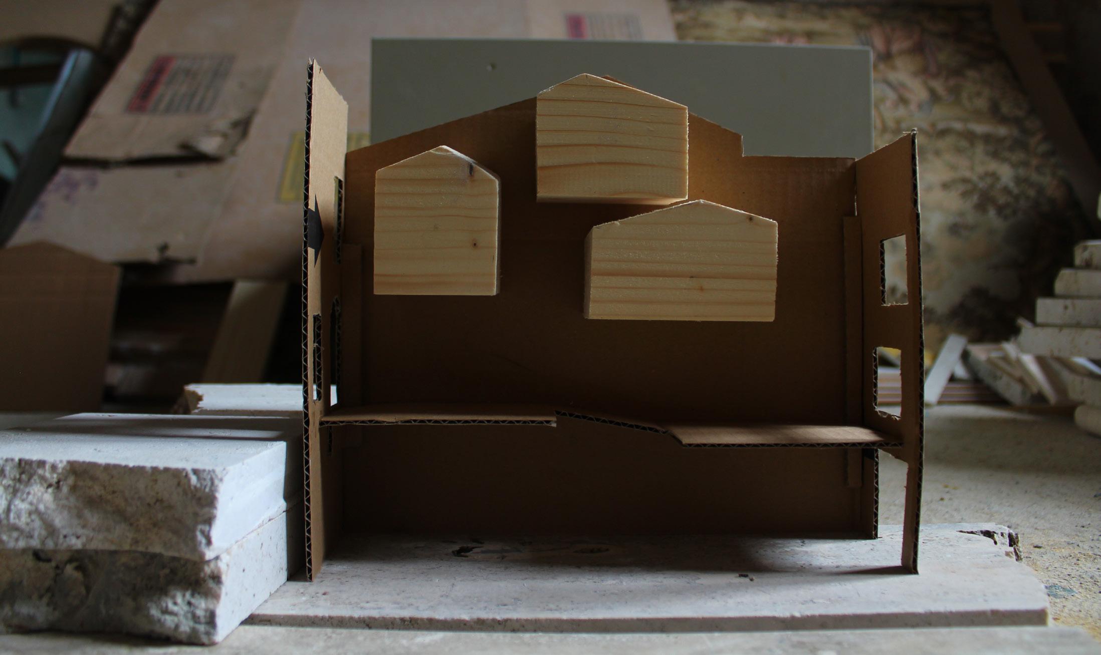
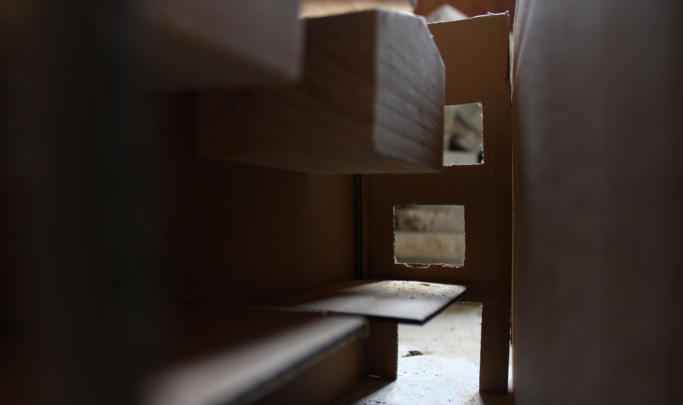
The model was based on the precedent design with the internal pods positioned in their original location. After an internal shadow analysis, the pods were moved into different positions to identify which crated the desired level of light and shadow to form a comfortable internal environment.

36 37
Figure 20. A scaled model was key to developing the internal pod arrangement.
Figure 22. A number of light source positions was used to ascertain the internal conditions, dependent on window opening location and size.
Figure 21. Using natural sunlight this helped achieve accurate shadow and light projections.
Light and Shadow study
Using the internal timber pod models, an analysis of the light conditions from an Easterly direction was done to capture how the light and shadows they formed. This exercise was key to the final placement of the internal pods to reduce overshadowing between pods and to also ensure a good level of natural light was able to penetrate into the space. The model analysis and shadow study created a number of design parameters that were set before moving forward to further developing the proposal:
DESIGN PARAMETERS

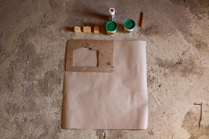

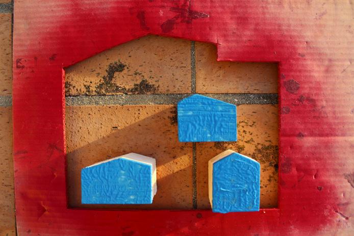


1. Natural light to reach all of the pods, either from the external walls or via roof lights.
2. Minimal overshadowing from adjacent pods.
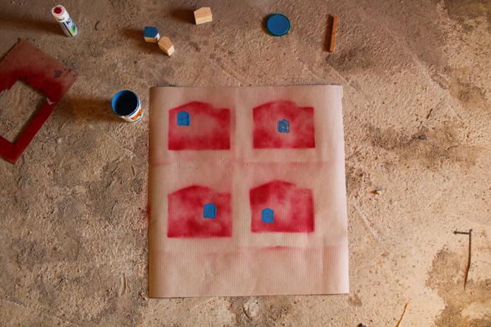
3. Clear central void through the building.

4. All pods to be located above the lower level.

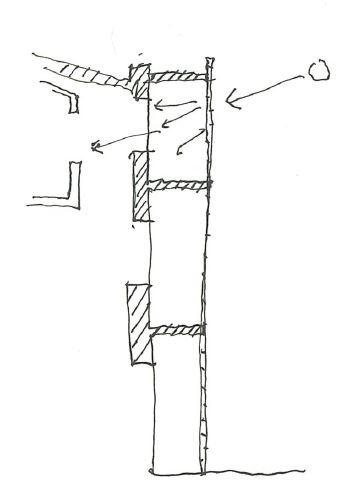
To reduce and control solar/heat gain during the hot summer months in Belmonte, research into solar shading solutions was done.
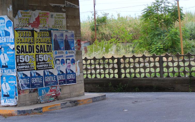

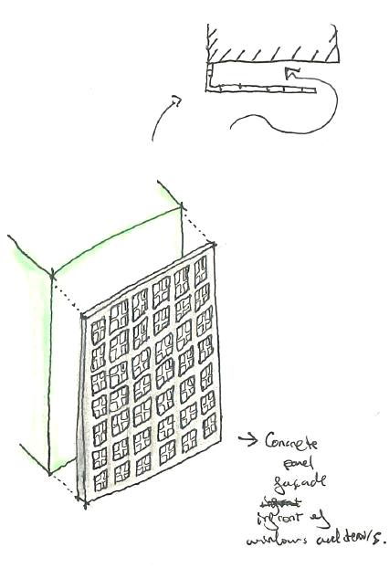
A key feature found on site was some precast concrete panel fencing. By using the shape and pattern this would be cast into larger panels and fixed to the West and East elevations, providing dappled shade and controlled levels of light entering the building. This external layer of cladding would also provide a level of weather protection from wind and rain.
38 39
Figure 23. Print making, study of light and shadow through alternative pod arrangements.
Sketch 6. Cast panel system acting as brise soleil, providing weather protection and shading.
Figure 24. Concrete panel fencing on site.
Sketch Overlay


A section view photograph was taken and used as an underlay to sketch over. The aim of this exercise was to quickly sketch out a series of the design elements that would form part of the overall design.

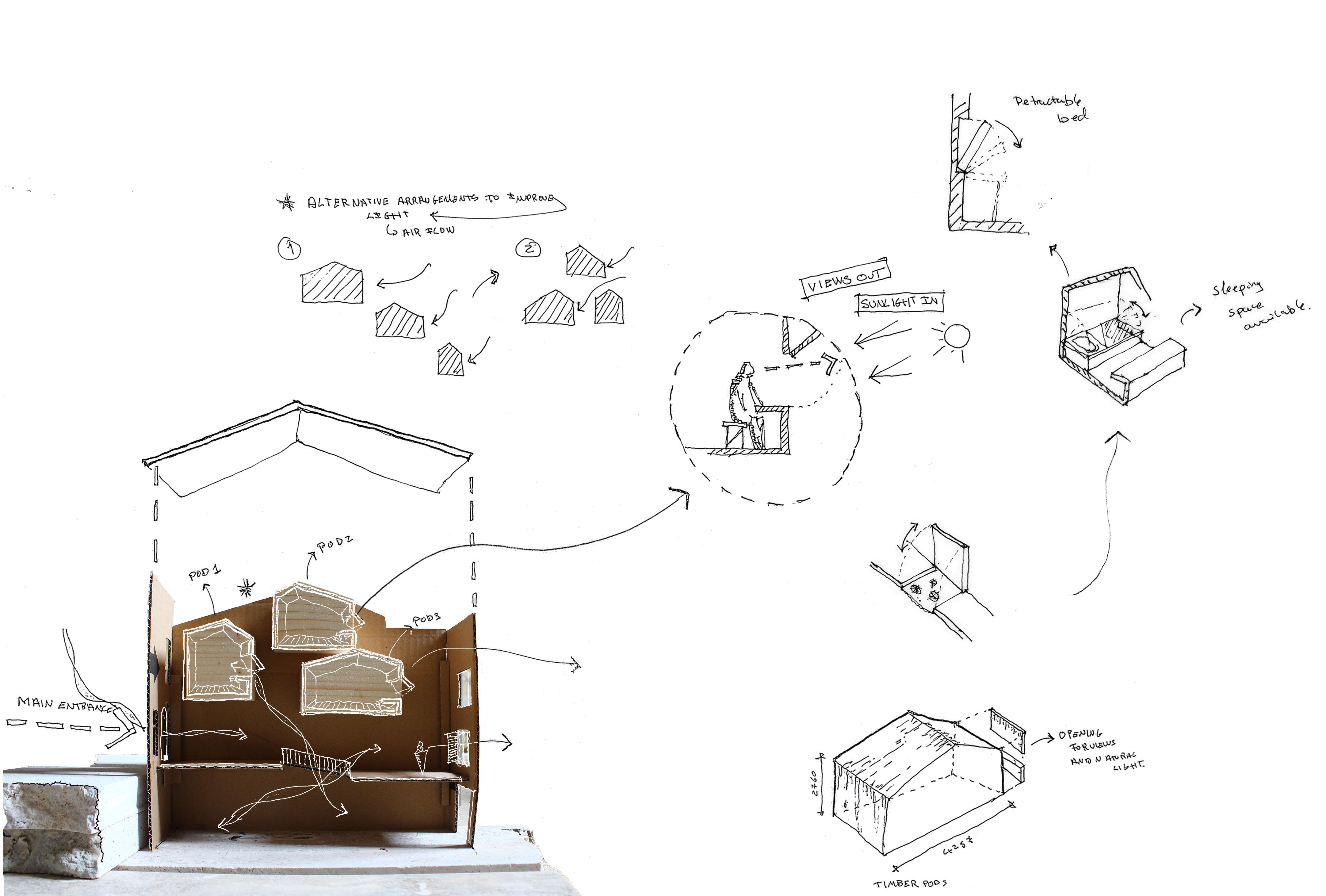
Below a list of the sketch studies:
- Alternative arrangements for the internal pods. This was developed alongside the shadow and light exercise.
- Orientation of the living pods. Each pod had to be suitably located to receive natural daylight and also have views outwards.
- Internal layout ideas for the living pods. The pods although small in size, would include creative storage and furniture solutions.
- Analysis of circulation flow and direction of views within the space.
Collage Overlay
By using alternative collage techniques, a preliminary view of the future pods on the site was able to be achieved. The collage uses a mix of CAD line drawing, photographs and block colours.
The use of an actual site image taken during one of the surveys, provided a good base reference for the perspective, and to gauge the overall scale and size of the proposals. The collage was a good starting point for an initial massing study, and a test run prior to developing a 3D model.
40 41
Sketch 7. Sketch overlay using the 1:50 model to analyse key features of the internal pods.
PROPOSED DESIGN - Tutorial Sessions
Being based in the newly formed studio in the Casa, our weekly tutorial sessions and key milestone Crit presentations would take place over video call, with the tutors Jane and Sandra and other fellow students joining the discussion online wherever they found themselves.

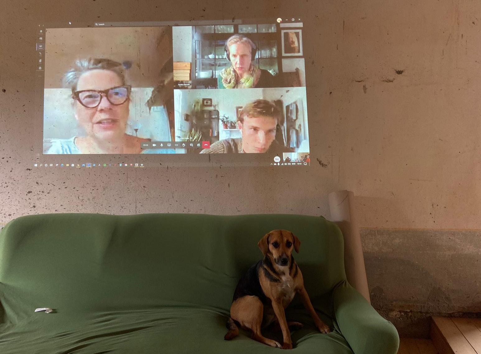
A series of weekly calls that helped the gradual design evolution from sketch concepts to 3D models. The sessions would generally start with a group discussion to put forward any new ideas or questions that may affect the overall Marina proposals, following on from the group discussions there was the opportunity to discuss in individual tutorial sessions our own project ideas.
TUTORIAL COMMENTS FROM SANDRA & JANE

1. Potential reuse of existing site or building features.

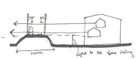
2. Work with sunlight and see the how different openings can affect the internal environment conditions.
3. Create a brief for the site for potential future sites and relocation.


MY ACTIONS MOVING FORWARD
1. Reuse of existing abandoned foundations on site.
2. Solar massing studies, using model and 3D sun-path diagrams to obtain the ideal location of pods and roof lights.
3. Moving forward into Brief 2, the aims and objectives of the first project are to be listed and applied into future site developments.

42 43
Figure 25. Online group tutorial session in the Belmonte Casa. (Autumn 2020)
Figure 27. Extract from author sketchbook. Notes during a tutorial session with Sandra.
Figure 26. Online group Crit presentations at home in the UK. ( Winter 2020)
Sketch 8. Development sketches before and after tutorial sessions.
Sketch 9. A communal dining space is aimed at bringing local and visitors together through food.
PROPOSED DESIGN - Developing the Project


To begin with, a number of sketches were done to further study the placement of the timber pods and the concrete solar shading panels. To improve the efficiency of the shading and weather protection, the panels were offset from the facade, leaving a natural air gap between the building and the panels. (Sketch 8 )
The main plan would be divided into 3 key areas; the circulation hallway, the private individual pods on the upper floors and a communal area on the ground floor.
A site section was drawn to ensure the positioning of the timber pods was above both the railway and the motorway, keeping the proposed sight lines free of any obstructions.
Being in close proximity to a flood zone the higher positioning of the pods also meant they were raised off the floor to reduce any potential impact from future flooding.
PROJECT COLLABORATION
The development of the entire foundation site was done in consultation with Hannah, who’s project also used the existing foundations. Through a number of iterations the site layout was developed to achieve an open communal piazza between buildings, a defined pedestrian circulation route and a shared community dining space.
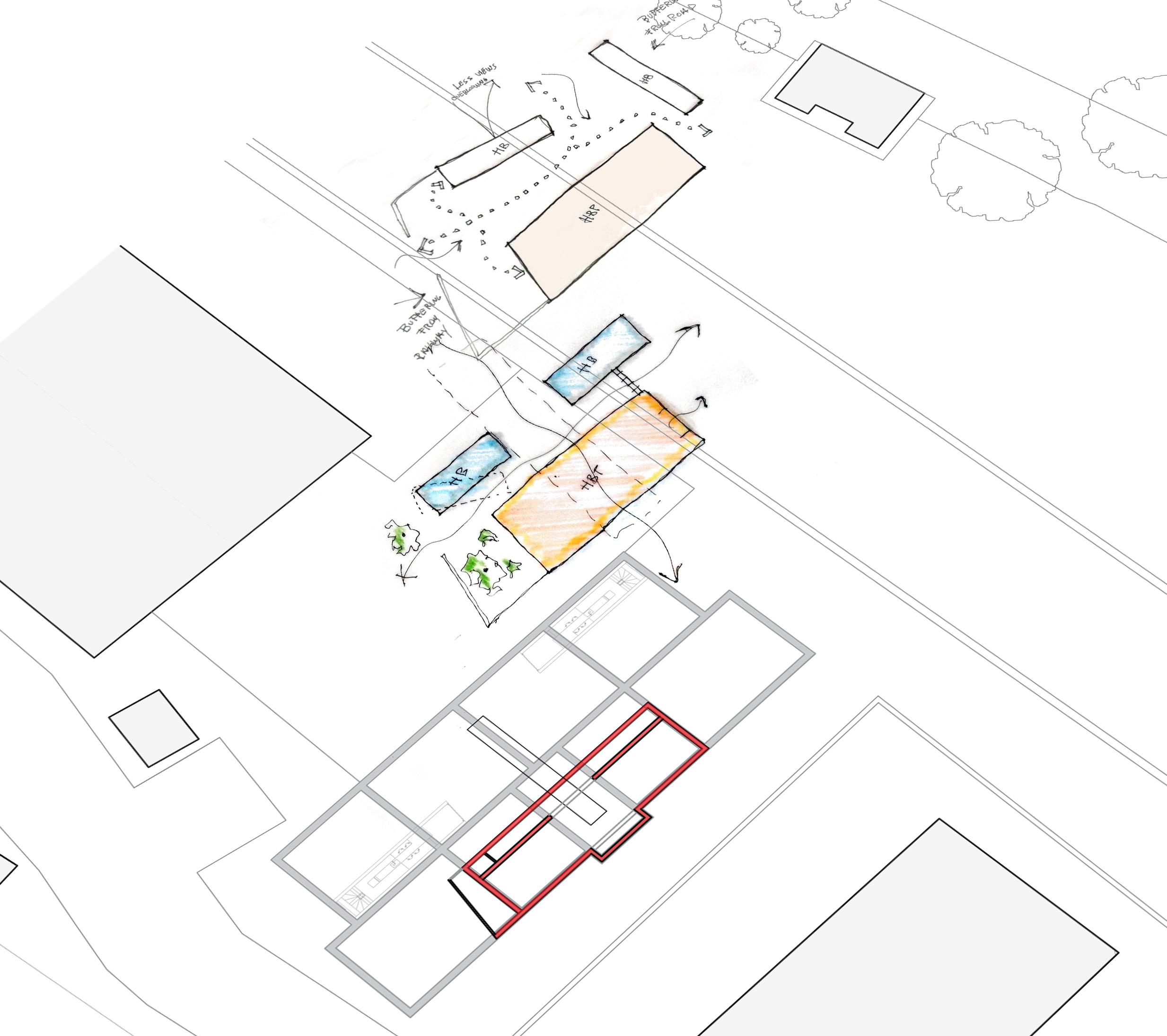
Above: Section sketch of proposed communal dining space.

Below: Isometric sketch of proposals.
(Pods, dining space and secondary facade)

44 45 View Level above railway Views to beachfront Views to mountain
View level above road
Figure 28. Layering of sketch proposals to reach the proposed layout drawn into CAD.
Sketch 10.
PROPOSED DESIGN - Material Selection
The nature of the project required that a selection of the materials should be resourced from the local surrounding area. Unfortunately materials such as concrete are sometimes inevitable but their negative carbon contribution can be balanced out by the use local sustainable natural materials and energy efficient design proposals.

To gain an overall view of the proposed materials, an analysis of each was produced depicting their positive and negative points both towards the site, sustainability and environment.
CONCRETE RAMMED EARTH


RESEARCH
Due to the site location in close proximity to a flood area, immediately it was decided that the ground storey would need to be constructed from a water resistant and strong material, concrete was the primary solution due to inherently water- resistant properties.
A workshop during the 2020 Mudchute trip, introduced us to recent local applications of this technique in making community ovens within the surrounding local towns.
RESEARCH
Earthen buildings have existed in all of Italy since ancient times, and therefore it was key to include this construction method in the project. Further research lead to discovering the technique of Adobe, a particular skill of earth ramming that uses straw also known as vreisti, bresti or mattunazzu. This technique is still currently used and features the fine-grained earth found in the region.
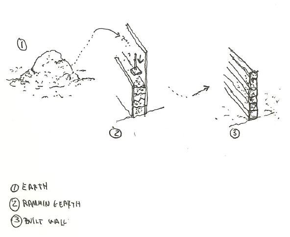
A workshop during the 2020 Mudchute trip, introduced us to recent local applications of this technique in making community ovens within the surrounding local towns.
TIMBER PODS LIMESTONE & RECLAIMED STONE
RESEARCH
The timber pods are to be constructed using a off-site assembly process, most likely to be of similar construction as SIPs panels in a controlled weather tight factory. A rigid insulation core sandwiched between two timber panels, to form a strong and airtight structure.

SIPs construction means the pods can be fully manufactured off-site, installed with the required electrical, ventilation and plumbing services. And then transported to site via the railway and immediately craned into position. Leaving just simple connections to be made into the preinstalled services systems.
RESEARCH
Many of the older building in Belmonte Old town are derelict and unused, however they feature a local natural stone as part of the construction method. This can be reclaimed and reused alongside other natural stones that are predominant in the province.
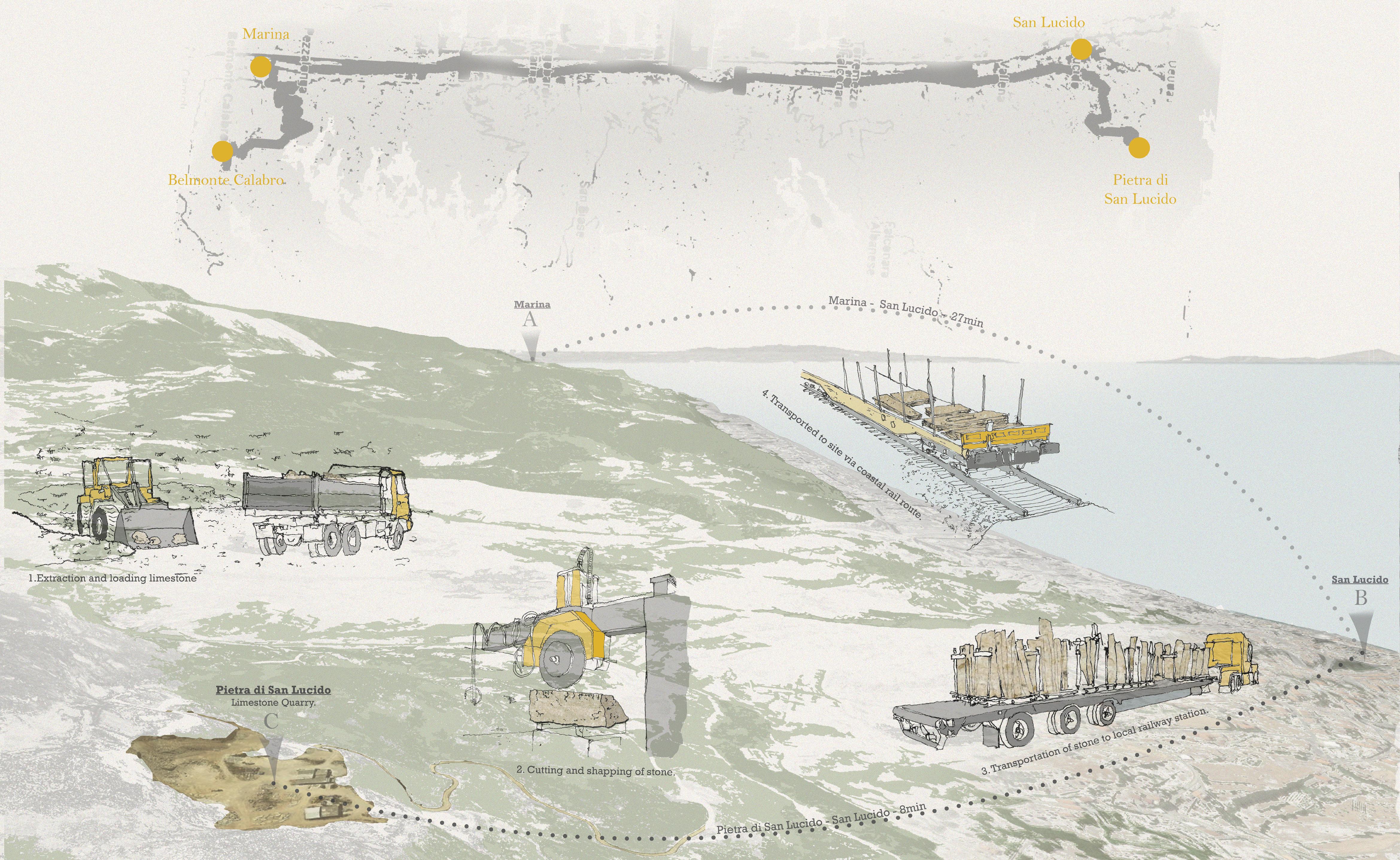
Further research into local stone lead to a small coastal town of San Lucido approximately 15km from the site. A couple of minutes in-land, buried in the mountains, is a Limestone quarry named Pietra di San Lucido
This material was a great example of local available resources, a diagram was produced to show the overall extraction/transportation process as well as calculating the embodied carbon energy generated to do this.
Further information into the application of the proposed materials can be found in the subsequent chapters 4 & 5.
SUSTAINABILITY
The industry has seen improvements in the sustainability of concrete usage and reducing CO2 emissions from cement production. Concrete can also be recycled and reused as an aggregate to reduce the amount destine to land fill.
PROJECT APPLICATION
RIBA PLAN OF WORK
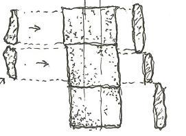
Material resourcing could form part of the outline specification review. In the RIBA plan of work this would coincide with “Stage 2 Concept Design”
To be used on the ground storey of the building and provide an foundation for the rammed earth walls above.
SUSTAINABILITY
Rammed earth is a highly sustainable material with inherit natural fire resistance, high thermal mass capabilities and low embodied energy.
PROJECT APPLICATION
To be used as the external envelope of the building above the ground storey.
SUSTAINABILITY
As well as the benefits of off-site construction, including no on-site labour disruption, reduced labour and a controlled assembly programme.
The airtight and thermally insulated pods will help reduce air leakage, noise penetration and mainly reduce heating requirements.
PROJECT APPLICATION
Individual isolated living pods.
SUSTAINABILITY
A natural abundant material that is cost effective, and due to its location would require less transportation to site as opposed to an alternative.
PROJECT APPLICATION

Cladding to concrete walls.

46 47
Sketch 11. Rammed uses natural and local material and is a simple sustainable method of construction.
Author Image: Rammed earth presentation. Mudchute Workshop 2020
EMBODIED CARBON CALCULATION - LIMESTONE


Pietra di San Lucido TO San Lucido Station (2km) via road 22 - 36 tn lorry = approx. 0.32 Kg of CO2 e/tn
San Lucido Station TO Marina Di Belmonte (15km) via rail = approx. 1.80 Kg of CO2 e/tn
TOTAL Carbon emissions produced is approximately 2.12 Kg per tonne.
48 49
Environment, Services & Energy Proposed Design
A number of strategies have been implemented into the site and building to improve the overall sustainability and efficiency of the scheme.
LIVING PODS
The formation of individual living pods for local retreats, visitors and remote working, means these spaces will be inhabited on a temporary basis, and would need to conform with nondomestic building regulations. Using a pre-fabricated SIPs system, the air tight pods will aim is to use a passive heating/ ventilation system, making the most of the inhabitants natural body temperature to provide the necessary heating, regulated using natural ventilation.
LANDSCAPING
A landscaping strategy that provides well-being benefits to the residents and enhance the local biodiversity. Minimise large areas of hard surfaces, by provide planting schemes within the foundation layout that aid water drainage during heavy rainfall seasons.
NATURAL VENTILATION
An internal layout that contributes to a natural ventilation strategy would be beneficial to the overall energy saving of the building. As well reducing the need for mechanical ventilation, and the necessary installation material, such as ductwork and vents.

ZONING AND THERMAL MASS
With local available material and traditional rammed earth construction methods such as “Adobe”, this would form the primary envelope of the building. The inherit thermal mass properties alongside a secondary facade system can help regulate the overall internal temperature, with a mix of natural and artificial construction.

RIBA PLAN OF WORK

Service integration would normally form part of the coordination process between disciplines post planning. In the RIBA plan of work this would coincide with “Stage 4 Technical Design”

50 51
LANDSCAPING THERMAL MASS LIVING PODS SECONDARY FACADE
Figure 29. Isometric view of proposal.
Living Pods
The pods will use an off site construction method completed in a factory, commonly known as SIPs, in its simplest form it uses two boards of OSB fixed either side of a rigid insulation core, overall they form a lightweight thermally efficient panel with structural capabilities.
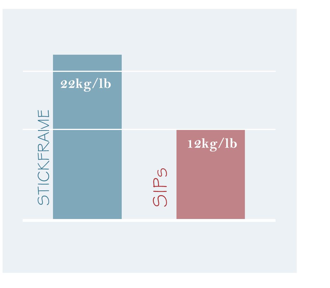
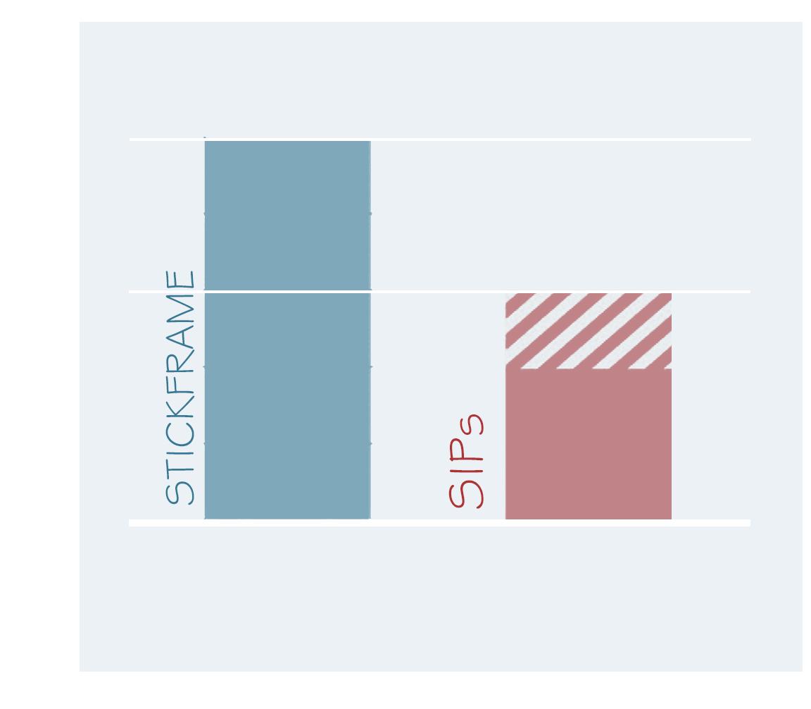
One of the biggest benefits to using this system is that the panels can be fixed together to form an airtight space, which can then be uniquely climate controlled to alter the internal environment suiting individual needs. Helping minimise air leakage and consequently reduce heat loss in winter or cold air loss in summer, overall reducing mechanical heating and cooling systems.
As well as sustainability benefits, this method of fabrication helps reduce on site workforce and minimise potential delays from weather or unforeseen circumstances, by undertaking the construction in a factory controlled environment.
INTEGRATION OF SERVICES
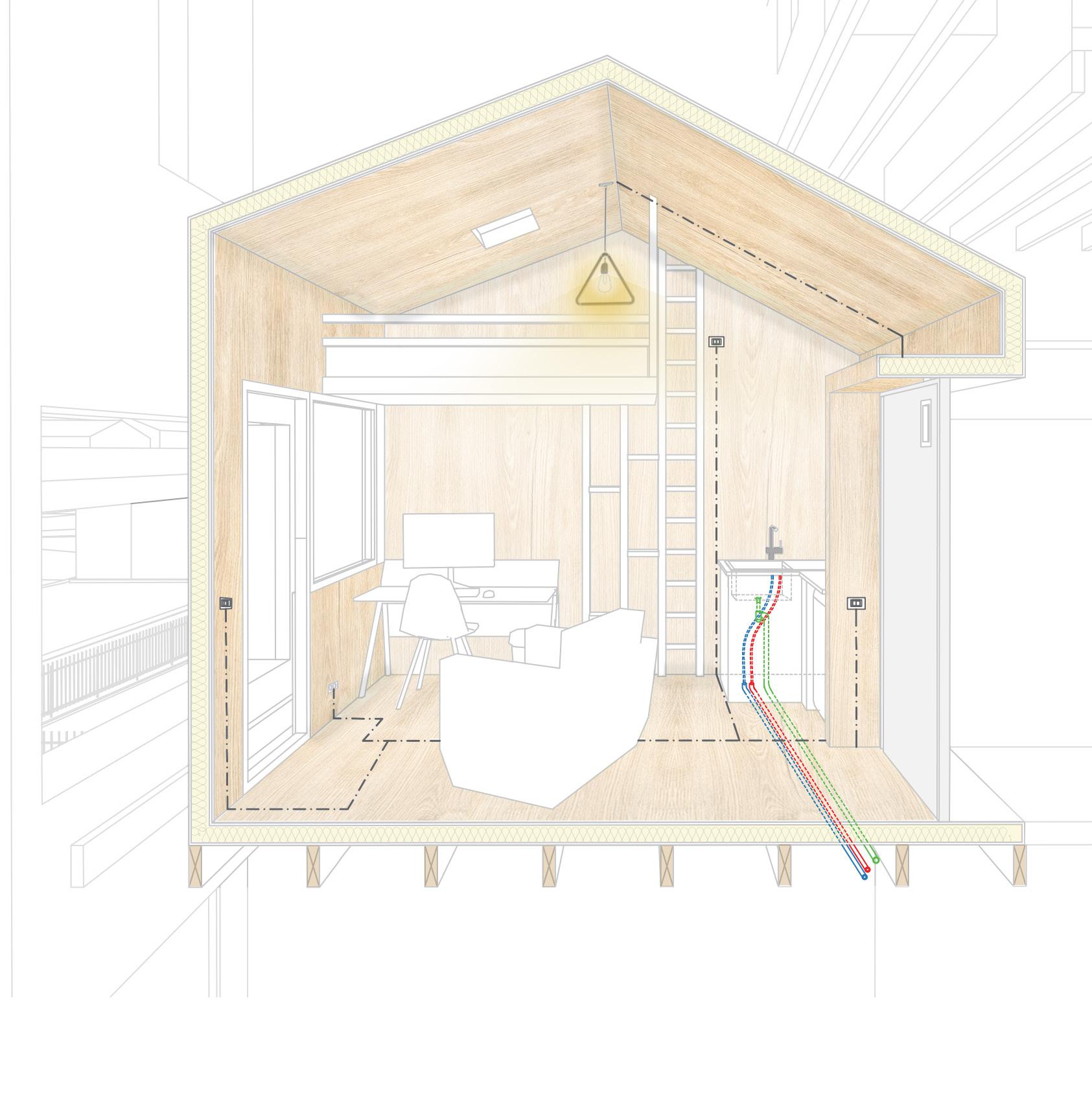
During the assembly process, pre-installed service channels and voids can be installed to allow future installation of electrical circuits.
To be able to achieve the full benefits from an airtight environment, any services and SIP panel penetrations need to be properly sealed, to ensure no air leakage is possible. Requiring taped up joints between panels and rubber seals for any service pipes that are cut through the SIP panel.
A common method used to calculate building efficiency and energy usage and to ascertain compliance with Part L2 of the Building Regulation, is called SBEM Calculations (Simplified Building Energy Modelling)
Once assembled each pod can be individually tested to check they meet the air tightness and energy efficiency requirements set out in the Building Regulations.
Further research into required U-values will be undertaken in the “Construction” chapter.


A void between the SIPS panels and finished veneer panel will allow for necessary electrical cable runs.

From Plant Room
H & C water To Soakway Greywater
Hot & Cold water will be supplied under the floor in between the joists from the main plant room. Greywater will be extracted to a new Sustainable Drainage system (SUDs)

52 53
LESS ENERGY USAGE SIPs building can save between 40-60% energy SIPs building can reduce by 45% CO2 emissions MORE SUSTAINABLE
Sketch 12. Concept sketch for timber pods.
Figure 30. Perspective view of timber pods with services
Landscaping


An external works plans was developed to include new planted areas and soft landscaping, providing a natural space for inhabitants, alongside minimising the effects of potential flooding during periods of heavy rainfall.


The main planting scheme is to be located within the remaining spaces of the foundations. With the Marina featuring a Mediterranean climate, with hot dry summers and cool, wet winters, it is important the plants used are local species that are able to sustain the change of climate throughout the year. Trees such as pine and oak are common to the area and can provide good amounts of natural shading, in combination with low shrubs and aromatic plants such as, sage, rosemary and wild fennel, overall forming a scheme with variety.
Engagement with a biodiversity/ ecology specialist alongside input from a landscape designer will ensure that the proposals are in keeping and appropriate for the site, as well as minimising potential negative ecology views from local planning authorities.

54 55
1. Low level shrubs and aromatic planting
2. Raised wooden walk way.
3. Proposed Building.
4. Native tree species such as Oak, Pine and Fig.
5. Adjacent student site. (Hannah)
6. Shared communal dining table.
2.
1.
3.
4
5.
6.
Figure 32. Photographic collage of landscaping scheme. View looking West towards Tyrrhenian Sea.
Sketch 13. Initial concept sketch
Figure 31.Top view of landscaping design.
Natural Ventilation
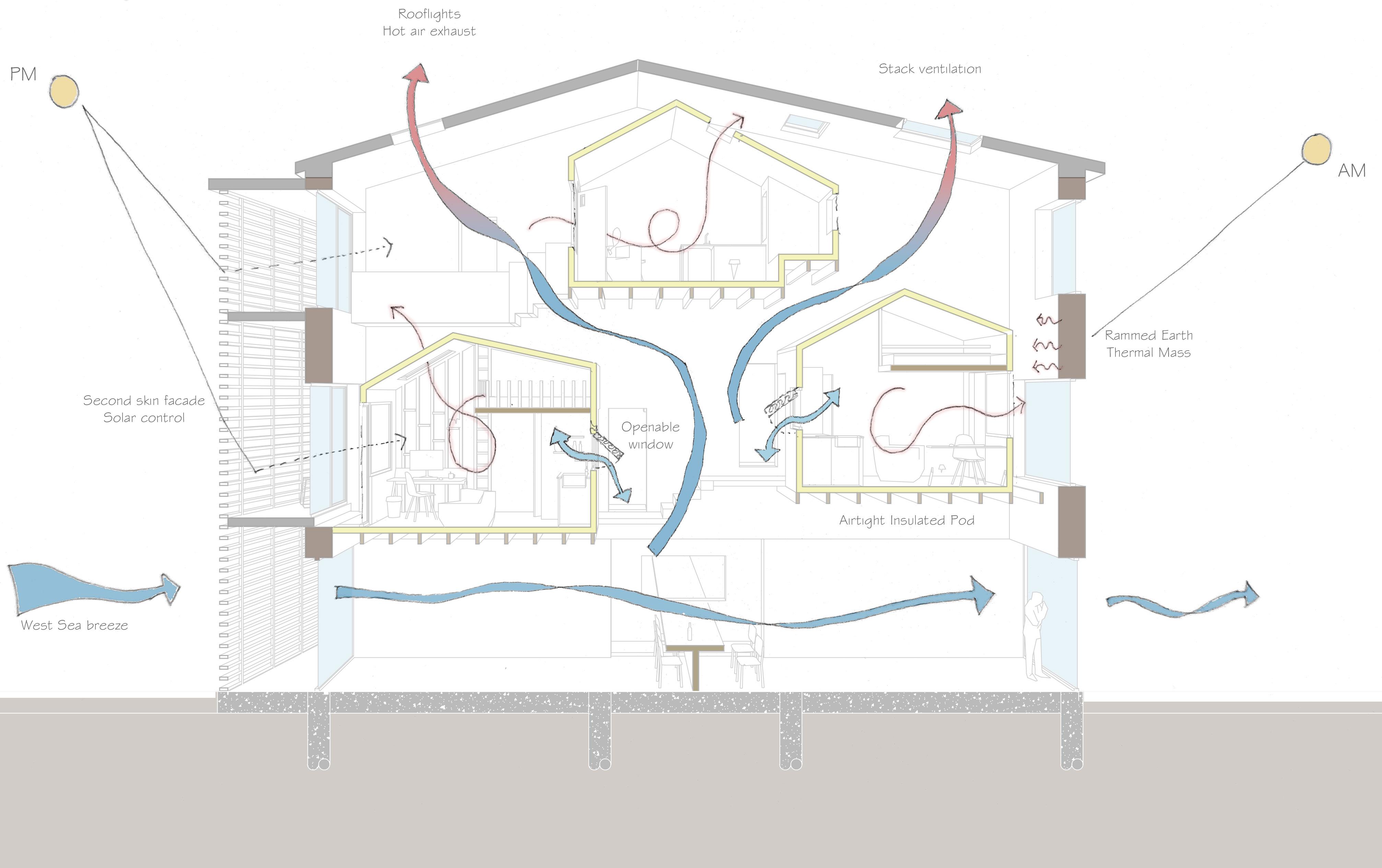
Due to the inherit location of the site in the Marina, located in close proximity to the Tyrrhenian Sea, the site benefits from a natural westerly sea breeze that is drawn inland to the mountains. The proposed building has been set out to make the most of this to reduce overall carbon emissions.
The design is centred around a stack ventilation system that relies on a difference in pressure from outside to inside, drawing the air from the bottom of the building to the top by passive means.
Large windows located on the ground floor can be opened to allow fresh air to be drawn into the building. A number of roof-lights located approx. 10m above the ground act as stacks to draw the naturally rising warm and stale air out of the space, leading way to fresh air incoming from below.
By placing the internal living pods at a higher level they can benefit from the rising fresh air produced by the stack effect. Operable windows that can be opened by the inhabitants will allow a supply of fresh air.
REGULATIONS (UK)
For new buildings in the UK, the Building Regulations Part F provides guidance on how to design the ventilation provision, and provide appropriate means of reducing pollution build up in internal spaces, protecting the inhabitants health and well-being.
SUSTAINABILITY BENEFITS
• Overall reduction in CO 2 emissions due to removing the need for mechanical extracts.
• Gives occupants control of the internal environment
• Requires much less maintenance than conventional systems.


56 57
Figure 34. Section showing natural ventilation strategy and solar exposure
Zoning & Thermal Mass
The use of rammed earth in the proposed building is very important. By using a natural, readily available material it can significantly reduce the carbon footprint, as opposed to transporting new material to site. A minimum wall thickness of 500 mm will allow the inherit thermal mass properties to slowly soak up the heat from sunlight during the day, to then slowly release this in the evening during the winter months, helping to reduce a drastic change in internal temperature and the need for large supplementary heating systems. On the other hand, during summer months the thick earth walls will protect the internal space from harsh UV rays, reducing heat penetration from solar gain.
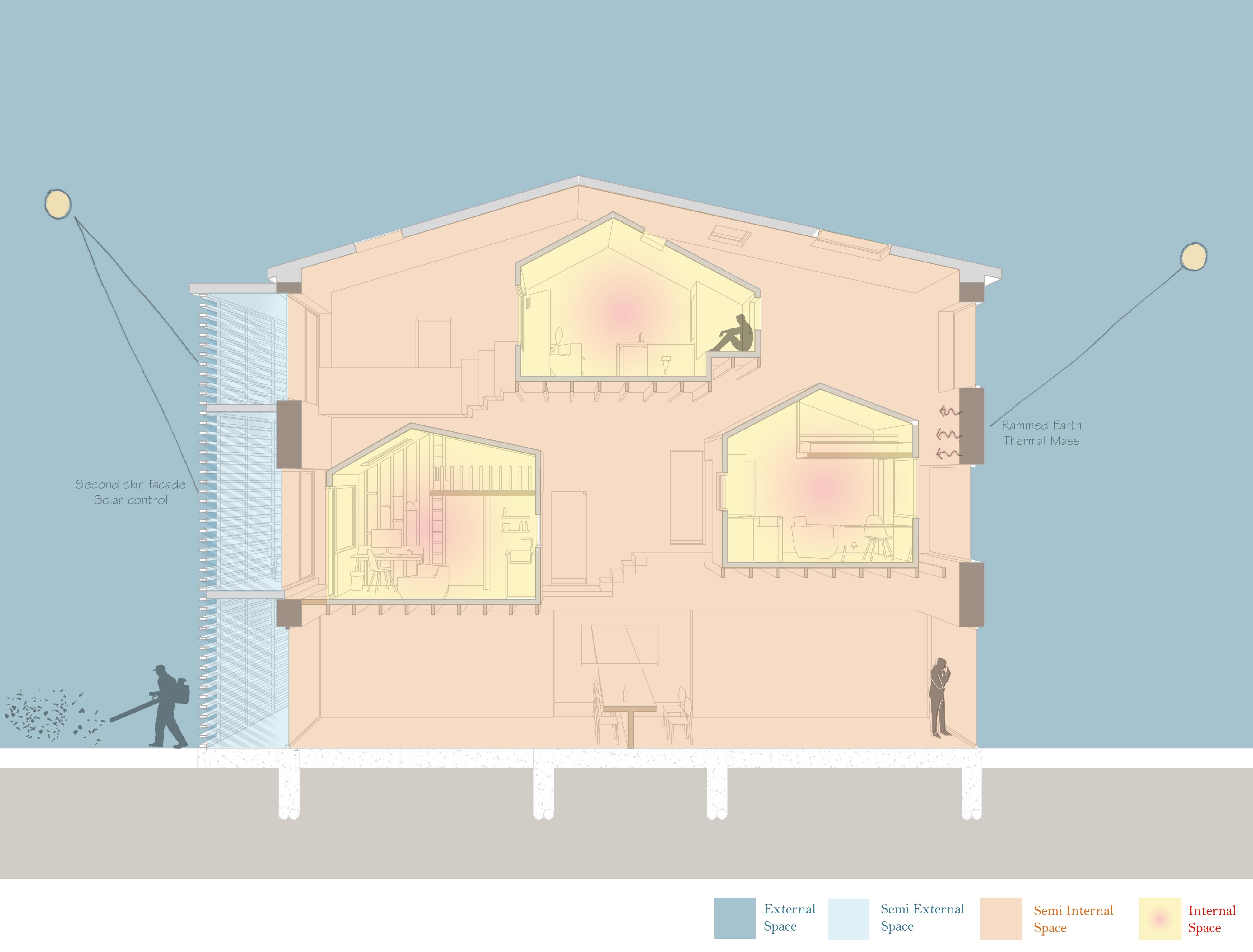
Working in conjunction with the rammed earth walls is a zoning strategy, designed to protect the internal living pods. The first layer of protection is a secondary facade that creates a pocket of shaded cool air (semi external space), the proposed location and design of this would be further investigated through CAD thermography, which can simulate annual sunlight on the site to properly locate the solar shading. Secondly, the pods are suspended within the rammed earth walls (semi internal space), the temperature and environment of which are controlled by the stack ventilation. Lastly are the pods themselves (internal space), fully insulated and airtight using the SIPs panel systems.
SUSTAINABILITY BENEFITS
• Rammed earth has inherit thermal mass properties, alongside being naturally fire proof, termite proof and breathable.
• Uses local natural materials.
• Low embodied energy.


58 59
Figure 35. Section showing zoning throughout the building
Sustainability Guidance, Regulations and Codes (UK)
If the project was to be located in the UK, from the initial outset of a project, there are a number of professional resources that can be used to embrace sustainable design and create energy efficient and low carbon buildings.
RIBA SUSTAINABLE OUTCOMES
The construction industry is begining to see a major reform due to the effects of climate change. Architects are being encouraged by the RIBA to start becoming more sustainability conscious throughout every stage of a project. The RIBA has developed the 2030 Climate Challenge report where they set out eight sustainable outcomes that can be delivered on any project size. The outcomes are designed to cut all operation energy and carbon emissions from the construction industry by 2030.
RIBA SUSTAINABLE OUTCOMES
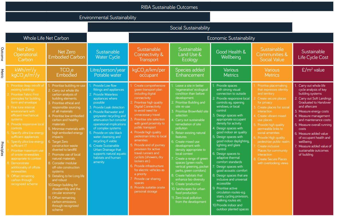
A number of these points have been focused on throughout the design of my project, these include:


1. Net Zero Embodied Carbon
- Prioritise building re-use; Incorporation of the existing foundations.
2. Sustainable Land Use & Ecology
-Create habitats that enhance bio-diversity; Incorporation of native species into the landscaping scheme.
3. Good Health & Well-being
- Design spaces to adaptive thermal comfort standards; Natural Ventilation strategies in combination with air tight living pods.
4. Sustainable Communities & Social Value
- Create secure places for privacy and social interaction; The building benefits from open communal areas and private accommodation.
BREEAM (Building Research Establishment’s Environmental Assessment Method)

One of the worlds most recognised independent sustainability assessment methods for the construction industry. The aim of BREEAM is to provide clients with a range of key principles and requirements that can help demonstrate the sustainability performance of their projects. Throughout the procurement of a projects planning, design, construction and operation, BREEAM helps validate the sustainability value of a building to achieve certification
Applied to my project, there are a number of steps that would need to be taken to achieve a BREEAM rating.
1. The client or agent would approach BREEAM to ascertain the standard that would apply to the project.
2. Appoint a licensed BREEAM assessor to oversee and assess the design compliance with the correct standard.
3. Register the project for assessment.
4. Assessment of the entire project procurement with assistance from the assessor.
5. The licensed assessor reviews the project information and determines the compliance against the BREEAM standard. Points are awarded to different areas of the project as to whether they satisfy the project standard. Overall this will determine the BREEAM rating.
6. Assessor submits the assessment to the main certification body to ascertain a final decision.
7. Receive BREEAM certification and rating.
BUILDING REGULATIONS
In the UK there are a number of statutory Building Regulations set out by the Government that any project will need to comply with before occupancy. These are approved by a Building Control officers who ensures a building meets the required standards of construction and design.
Specifically for environment, services and energy there are 3 approved documents that would apply to this project:
- Approved Document F: Ventilation.
- Approved Document L2A : Conservation of fuel and power.
- Approved Document O: Overheating.
Most commonly the architect would work closely alongside Mechanical and Electrical engineers, as well as Energy and sustainability specialists, these can provide advice and technical support to ensure compliance with the approved documents and overall produce a building that encourages carbon reduction and energy efficiency.
Other approved documents will need to be consulted for different aspects of a project. These will be discussed in the following chapter “Management, Practice & Law”
60 61
Figure 36. RIBA list of sustainable strategies.
Figure 37. Source BREEAM.com
Figure 38. Government Building Regulations L2A
Structure, Materials & Construction Proposed Design
Through the design process, consideration has been given to the structure, through careful selection of materials and construction methodologies.
REUSING FOUNDATIONS
A prominent feature of the site is the existing foundation layout. Previously destined to become an apartment block, these will be cleared from overgrown vegetation and prepared to be reused as part of the foundations for the proposed building. This excercise would take place alongside a Structural Engineer to ascertain the viability of their reuse.
CONCRETE & RAMMED EARTH


The primary external wall superstructure is proposed to be a mix of cast in-situ concrete and rammed earth construction. The are a number of measures proposed to reduce the overall CO 2 emissions created from the use of concrete, a percentage of recycled aggregate is to be incoporated into the mixing process, and rammed earth walls will use local soil to minimise uncessary transportation of additional material to site, along with the naturally low embodied energy.

SIPs CONSTRUCTION
The isolated living pods will be formed using an off site SIPs construction. Individual wall/roof panels are assembled to become a flat pack style structure which can be easily transported to site, assembled and craned into position once the outer rammed earth walls are constructed.
RIBA PLAN OF WORK
Consideration of a buildings materiality and structure can take place as early as Stage 2 during the concept design stage, and for a Stage 3 planning application, the first would need to be selected for consideration by the statutory bodies. A decision upon the structural frame could take place during Stage 4 “Technical design” and fabrication and assembly in the subsequent Stage 5 “ Manufacturing and Construction”

62 63
CONCRETE & RAMMED EARTH WALLS SIPs CONSTRUCTION RE-USING FOUNDATIONS
Figure 39. Exploded Isometric view of proposed building components.
Reusing Foundations
Further research into the reuse of existing foundations was done to gain and understanding of the formal process required to ascertain the viability of foundations.

The institution of Structural Engineers provides A short guide of reusing foundations. Of which key points have been shown below:
BENEFITS AND SUSTAINABILITY
The reuse of key structural elements such as the foundations can lead to significant savings in cost, programme and materials, in addition to being more sustainable and environmentally friendly.
RESPONSIBILITY AND RISK
When attempting to reuse foundations the risks need to be considered and addressed at an early stage of the project. Structural and geotechincal designers will need to work closely to ascertain the structural viability of the foundations.

INVESTIGATIONS
The dimension of foundations, construction defects and possible deterioration are all typical unknowns, therefore the requirement for intrusive investigations may be necessary. Consideration to ground conditions and original workmanship can also be the key to any hidden defects.

DESIGN


The biggest unknown is the existing load capacity, to ascertain this it is essential to understand the likely construction methodologies and design approach alongside any project records. During the design process “load factors” are used to relate allowable capacity and calculate the opportunity to reuse.
RIBA PLAN OF WORK
The above investigations would ideally occur as soon as possible once site access is available. In the RIBA plan of work this could coincide with Stage 1 “Preparation and Brief”
64 65
Figure 40. Existing foundations were overgrown with vegetation.
Figure 42. Collage of existing foundations.
Figure 41. Bore hole investigation into concrete slab
Concrete and Rammed Earth Walls
The primary ground floor walls are to be constructed on top of the existing foundation line. Due to the risk of flooding, the ground floor is to be a sacrificial zone, cast in-situ walls using recycled aggregate and local beach pebbles will help minimise the overall carbon production.

On top of the supporting concrete walls is to be the primary rammed earth outer skin of the building. This is to be constructed using a traditional technique called “Adobe”, as previously mentioned, this method uses local straw or reed combined with the local fine grain soil, to create a natural, low embodied carbon and sustainable construction material.
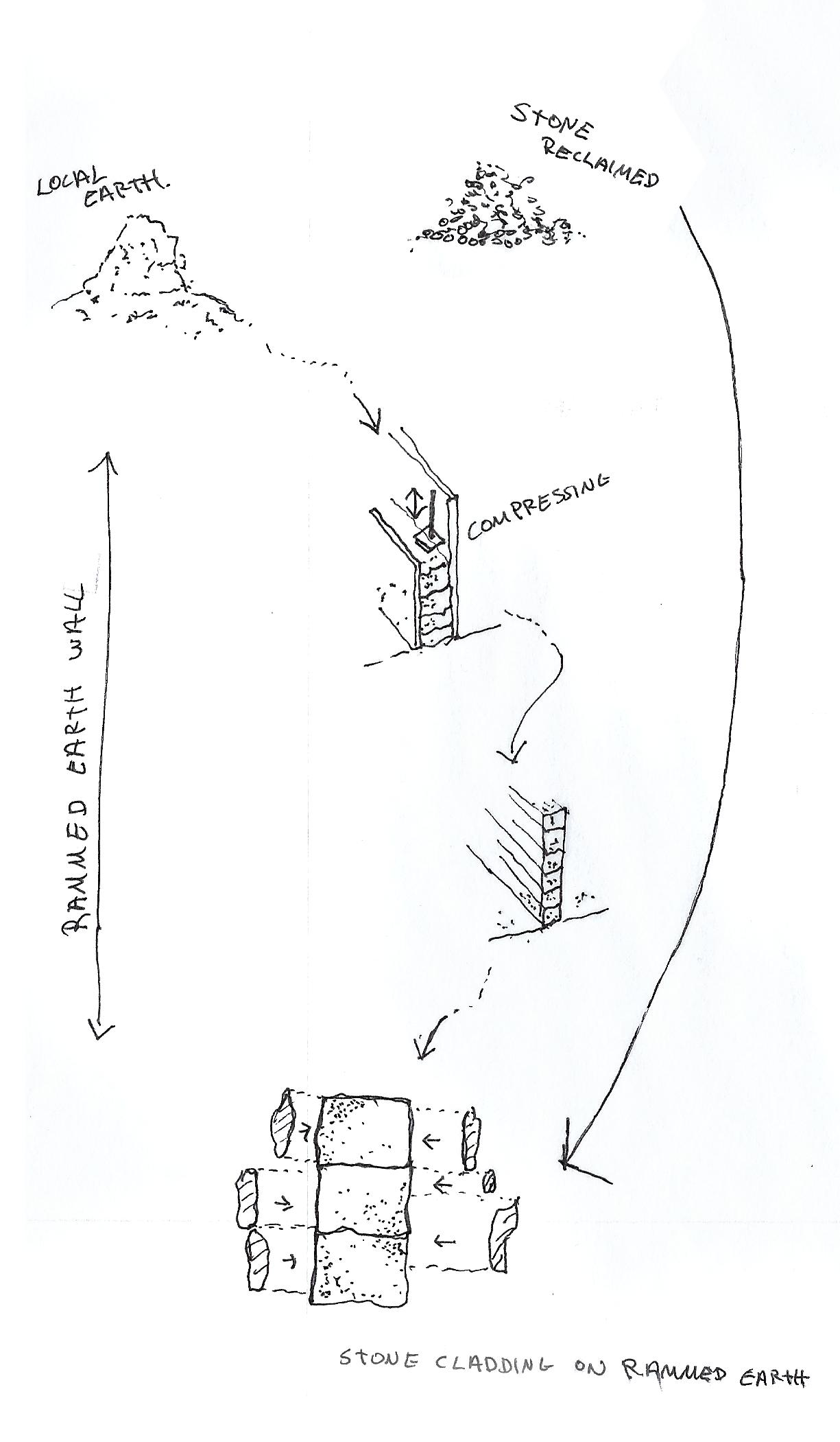
RAMMED EARTH CONSTRUCTION
Prior to erecting the walls, a number of sample testing, such as cohesion and shrinkage should be done to ascertain the correct water to earth ration is used to maximise the wall strength. Test walls and sample cubes may also be done to test compression strength and drying time.
1. A formwork structure is erected using plywood boards.
2. A layer of moist soil with reed is added into the formwork.
3. The earth layer is compacted down using a hand help tamper or pneumatic alternative. This depends on the site conditions.
4. Subsequent layers of moist soil mix are added and compacted.
5. Once the desired height is achieved the walls are left to dry and cure, before the formwork can be removed.
SUSTAINABILITY BENEFITS (Rammed Earth)
• Potential 90% less wastage produced on site. Production is taken off site into a factory.
• Airtight construction to reduce cold bringing.
• Reduced on-site labour.


• Good thermal performance.
• High levels of sound proofing.
66 67
Sketch 14. Sketched process diagram or rammed earth wall construction.
Figure 43. 1:20 Section Detail of proposed external wall and internal pod.
SIPs Construction
The individual living pods are to be constructed using SIPs panels, or Structural Insulated Panels. This innovative modern method of construction uses a panel system formed of a foam insulation core (EPS), sandwiched between two structural grade Orientated Strand Boards (OSB). The EPS insulations is an expanded polystyrene that does not degrade over time and is 100% recyclable.


SUSTAINABILITY BENEFITS
• Potential 90% less wastage produced on site. Production is taken off site into a factory.
• Airtight construction to reduce cold bringing.
• Reduced on-site labour.


• Good thermal performance.
• High levels of sound proofing.
68 69
4. Prefabricated SIPs panel
5. Insulated window frame with airtight seal.
6. Double glazing.
1.
2.
3.
4.
5.
6.
1. Insulated door panel with airtight seals.
2. Oak veneer lining
3. Softwood timber battens
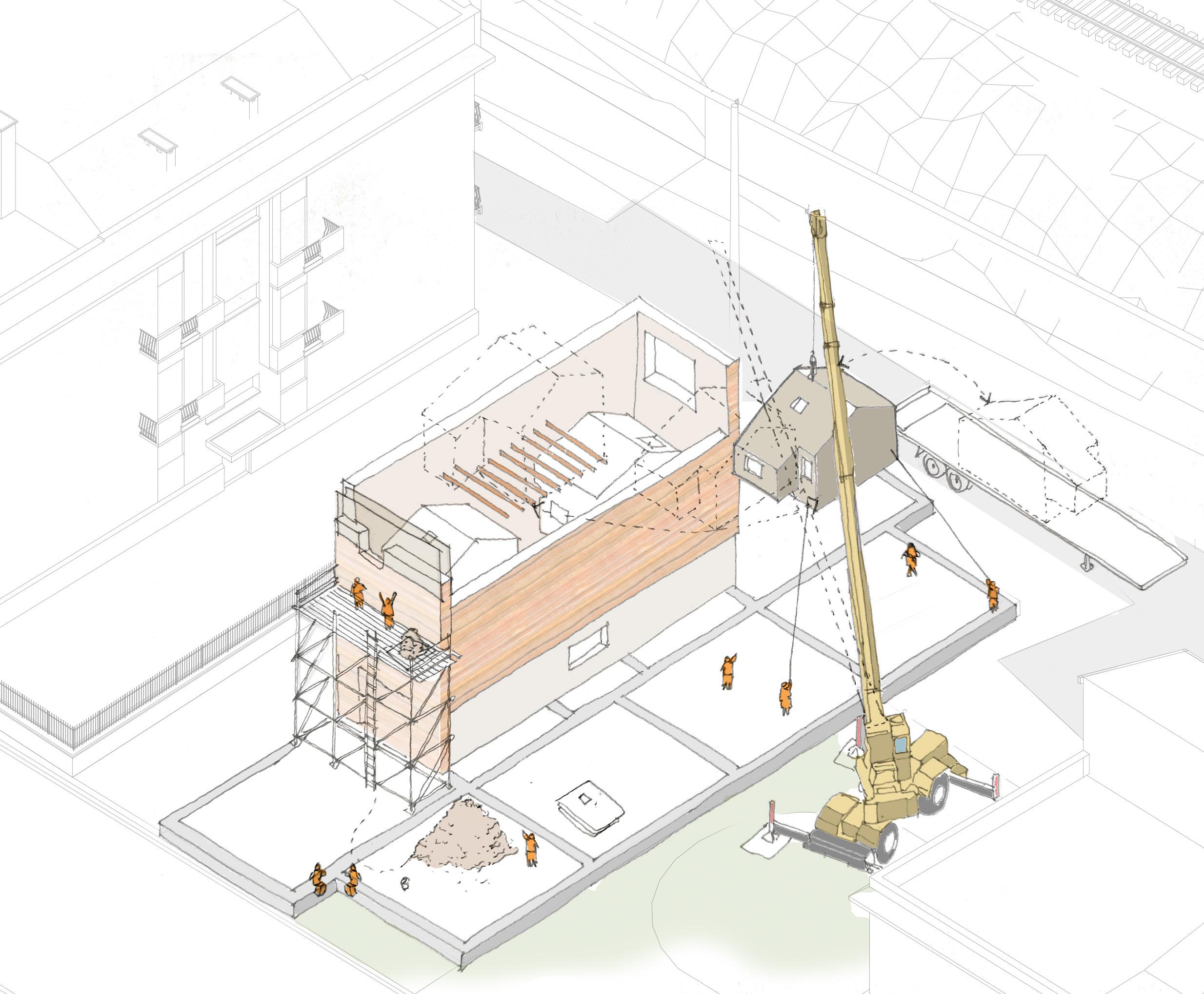
Figure 46. On-site construction sequence of Rammed Earth and SIPs pods.
OSB
OSB
Foam core
Service ducting
Internal Ash veener
Figure 45. Pod wall build-up
Figure 44. Exploded view of living pod components
Building Regulations
BUILDING REGULATIONS PART L CONSERVATION OF FUEL AND POWER.
As set out in the UK Governments Building Regulations Part L for the Conservation of fuel and power. To limit heat gain and loss, non domestic building elements should target the following thermal resistance standards:
Element Type Max. U-Value W/(m2.K)


Roof (Pitched) 0.16
Wall 0.26


Floor 0.18
Rooflights 2.2
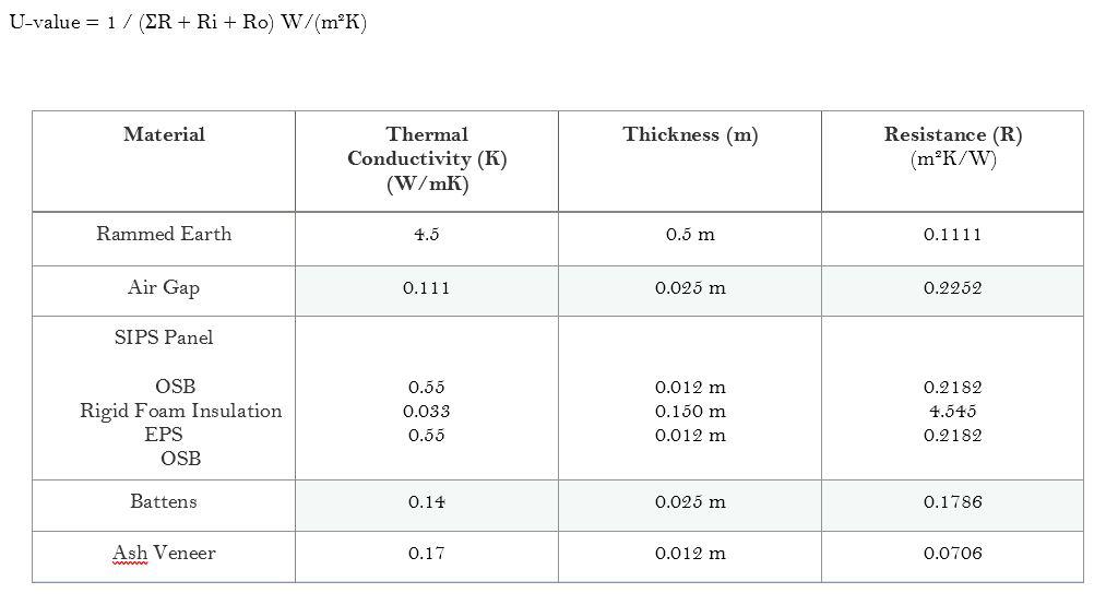
By using these calculations on each element of the building, we can ensure the proposed materials and design are in compliance with the regulations standards. If not, alternative materials, specification and design should be considered.
A U-Value calculation table has been done for the external wall build up and the ground floor slab, this is to ensure that they are in compliance with the relevant Building Regulation.
The design of the external wall detail, as shown in figure 33, was developed in conjunction with the U-Value figures and the SIPs panel insulation thickness was increased to bring align with the regulations.


BUILDING REGULATIONS PART K PROTECTION FROM FALLING, COLLISION AND IMPACT.
Approved document K is prepared to ensure buildings meet the required standards to minimise the risk of fall or injury from staircases, ramps and general use of the buildings windows and doors.
The proposed design features a number of staircases and therefore its important to consider the overall geometry and layout in accordance with its use. Considerations such as, the rise and going of each step, handrail height, landing areas and distance of door openings to the top of steps.
Key Dimensions
a: Staircase width min. 1000m

b: Step riser 190mm
c: Step going: 250mm
d: Handrail overhang from step edge min. 300mm
e: Headroom of at least 2000mm
f: Handrail height min. 900mm
g: Balustrade height min. 900mm
h: Door opening from step edge min. 400mm
RIBA PLAN OF WORK
Integration of the Building Regulations can be done at the early stages of design, this can prevent unforseen design changes later on. An application for Building Regulations generally takes place at RIBA Stage 4 “Technical Design”
70 71
SIPs panel Rammed Earth Wall
Figure 47. External wall detail section.
Figure 48. Isometric view of proposed staircase design
U-Value for external wall
U-Value for ground floor
BUILDING REGULATIONS PART B FIRE SAFETY
Approved document B is prepared to ensure buildings comply with requirements for inhabitants to escape safely from a building. This includes means of escape, fire alarm systems, prevent the spread of fire/smoke within the building and performance of materials, products and structures.
In practice, engagement with a fire officer is key to developing a fire strategy /system that works both for the design and budget. In recent times regulations on fire prevention and spreading has become increasingly important and therefore its key to obtain an efficient and compliant design.
BUILDING REGULATIONS PART M ACCESS TO AND USE OF BUILDINGS
Approved document M is prepared to ensure domestic and non domestic buildings comply with requirements for users to access and use a building. This applies to areas such as the circulation of occupants throughout the building, positioning of electrical sockets and switches and WC provision at ground floor level.
Part M also sets out design guidance for disabled users, internal ramps and lifts.
Due to the early stage of the design not all compliance with the guidance is achieved. This is to be researched further in the developed design stages.
Regulations Incorporated into the Design : (not limited to)
- Corridors that form part of an escape route should be min. 1000mm wide.
- Escape travel distances in more than one direction should be 18m to the outside or a fire protected area.


- Smoke detectors throughout the building.
- Fire alarm system both audible and visual.


- Fire strategy plan to be displayed within communal and private pod areas.
Regulations Incorporated into the Design : (not limited to)


- Level approach from external hard standing.
- Electrical hardware installed to appropriate height.
The above plans shows an analysis of the proposed fire escape routes, along with fire sounders and smoke detectors in each of the pods and communal areas. The entire system would be connected to a central control panel, that would allow in the case of a fire, the emergency services to identify the particular area where the fire/smoke is present.
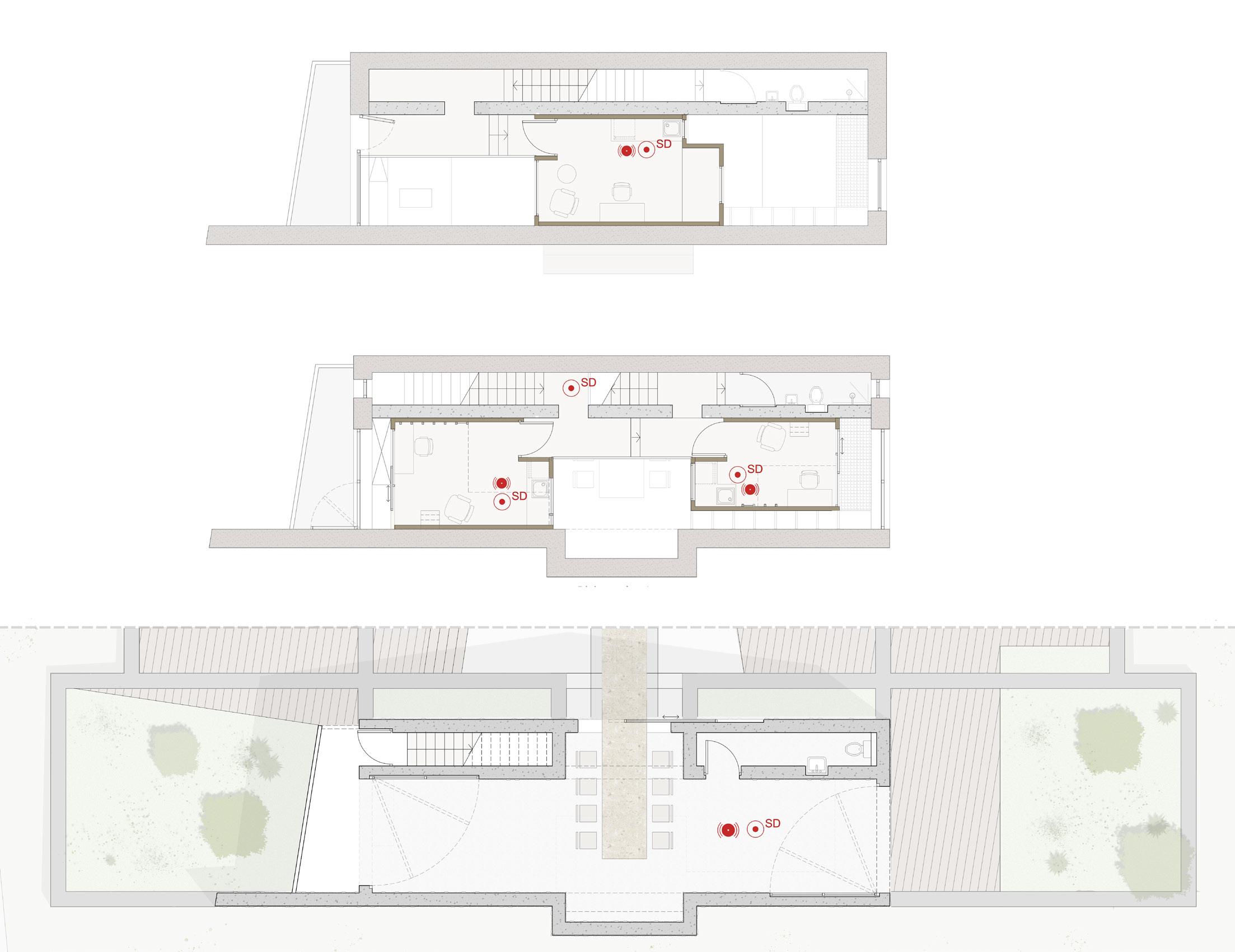
72 73 Fire escape travel distances Pod 1 : 12 metre to outside Pod 2: 14 metre to outside Pod 3: 19 metre to outside 1stF Pod 2 Pod 3
alarm GF 2ndF Pod 1
Fire sounder Audible and visual
Key
Ambulant WC
Fire Exits
AIMS OF CONSULTANT CRITS
Individual studio Crits were held to present the IDA projects to fellow students, tutors and invited professional consultants, I was chosen to undertake the Studio 3 presentation. The external practitioners were Ed Tricklebank from ARUP, a Structural Engineer & Saud Musinovic from Mott MacDonald, a Services and Sustainability Engineer. Along with tutors Sian Moxon and studio 3 tutor Jane McAllister.
The aim of these Crits was to pin up a small selection of work that would showcase the overall studio brief, with a focus on our individual projects, highlighting the challenges or struggles we may have come across. We were also asked to focus on technical design aspects, materials and structure and in particular the service and sustainability strategy we were considering for our site.
OVERALL FEEDBACK


The presentation and project were well received, although only a small selection of diagrams and images were talked about, the overall design and aims came across clearly, allowing the consultants to gain a brief but overall understanding of the project.
A few questions and comments were received from the critics, these have been bullet pointed below. A number of the suggestions have already been integrated into the design, however a few others will require a bit more research and alterations to fully integrate them into the design.
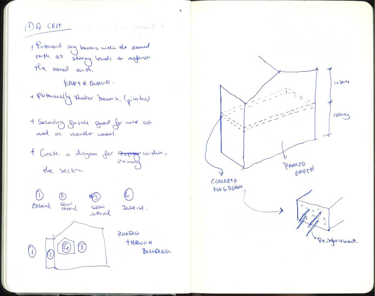
1. Due to the location of the proposed site in the South of Italy, and the risk of earthquakes, Ed Tricklebank suggested, that a potential concrete ring beam should be introduced at each storey level to reinforce the rammed earth walls.
2. Secondary facade is a good addition, acts as a brise soleil but also as weather protection.
3. The layout of the building in section drew the attention of Saud Musiovic, because of the proposed building layers, a diagram showing the zoning would be a good addition. Showing External to Internal.
COMMENTS FROM CONSULTANTS MY ACTIONS MOVING FORWARD
1. Integration of concrete ring beam in every storey for reinforcement.
1. Further research into the functions and design of ring beams will be needed before its integrated into the design. This is looked to be incorporated into the design of the 2nd Brief project.
3. Create a zoning diagram in section to show external to internal spaces.
3. A zoning diagram in section has been created and is shown in the Environment, Services and Energy chapter. This was a good exercise to visually communicate the External, Semi- External, Semi-Internal and Internal zones within the building.
74 75
Consultant Crits Presenting the project
Figure 49. Extract from author sketchbook. Notes during a Consultant Crit Session.
FutureBuild


Water Harvesting
FutureBuild is one of the UK’s largest exhibitions in the construction industry focusing on sustainability. It allows companies to showcase their innovative products with a goal to change the future of the built environment, and push the industry to the Governments goal of achieving net-zero carbon emissions by 2050.
ON SITE WATER MANAGEMENT
Due to the risk of potential flooding on site, I was keen to incorporate a water management strategy that would not negatively affect the existing rainwater run off, or increase the risk of flooding by new grey water generating services.
Whilst researching into the companies exhibiting at Futurebuild, I came across Rainwater Harvesting Ltd that manufacture a number of systems that could be incorporated into the building and site. The systems are of a bespoke design and made to suit the site requirements. The aim is to control the way water is discharged from the building and slowly released into the ground.
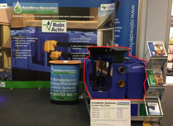
The proposed Sustainable Drainage system is aimed at reducing the rate at which water is discharged into the surrounding ground from the building.
The system is comprised of an underground tank that can both collect and harvest storm water and greywater from showers and sinks, and then control the discharge rate of into the ground. Overall the strategy can help reduce the strain on the existing drainage systems and collect excess water to avoid potential flood risk.
Sustainable Drainage underground water harvesting tank.
76 77
“SUDs Tank”
Underground Sustainable Drainage Tank
Greywater discharge into SUDs tank Rainwater collected into SUDs Foul waste discharge to local sewer
Regulated water discharge to site
Figure 50. Example of SUDs underground tank.
Figure 51 On site drainage strategy diagram.
Management, Practice & Law Proposed Design
For the proposed project it has been agreed that we are to apply the UK’s planning and building control guidance. However, there is a duty to ensure a basic understanding of the local legislation is obtained, therefore, an insight into Italian planning procedure has also been compiled below. This will also allow to see the key differences from each country.
Planning and Building Control ITALY
The primary source of law regulation design and construction is the Italian Civil Code.
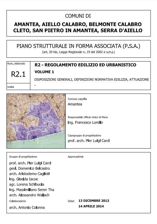
Much like the UK, Italy has its own fundamental principles for planning and building control at a national level. However, the land in each region is split into zones, with each one designated for a particular type of development. This zoning is determined by each municipality and can vary from region to region, the policies and regulations are compiled into the local “Regolamento Edilizio ed Urbanistico”
UK
Applied to the UK the site would be subject to the national planning policy framework (NPPF), which is overarching guidance that sets out the Government’s economic, environmental and social planning policies. Apart from this, each council will have individual Local Plans that are developed specifically for the area and solely for projects within the county. This will set out local restrictions, guidance and areas of development.

Independent surveys will also be necessary for a project of this type.
A Planning Checklists issued by the council will list all the necessary reports and surveys that will need to be carried out, this is to ensure all the necessary information is submitted to allow a informed decision to made.
The Municipal Structural Plan for Belmonte Calabro divides the area into coloured coded zones. Where each zones has specific building and construction regulations that will apply.

The proposed site lies within a zone designated as B2.1, the Building Regulations ( Regolamento Edilizio ed Urbanistico) defines this area to be almost completely built up featuring a defined building typology. The following categories of construction are allowed within this area:
- Restoration and conservation.
- Building Renovation
- Urban Restructuring
- New Construction
- Change of intended use.
Proposed Site


A number of restrictions would apply to this designated area and should be considered:
- It is mandatory to respect the existing road alignments.


- Accessibility must be retained.
- Existing architecture should be reused or enhanced to retain as much existing character as possible.
REGULATIONS ON CONCRETE USE

Due to the use of reinforced concrete on the low level walls, the law states that the specification and necessary testing certificates, should be submitted to the relevant public authorities prior to starting on site. Any final testing should be undertaken by the Civil Engineering Corps ( Genio Civile)
78 79
Figure 54. Extract from the Municipal Structural plan for the region of Belmonte Calabro and surrounding areas.
Building Regulations for Municipality of Belmonte Calabro
Typical example of UK Local Plan
Thyrrenean Sea
Figure 52.
Figure 53.
Procurement & Contract
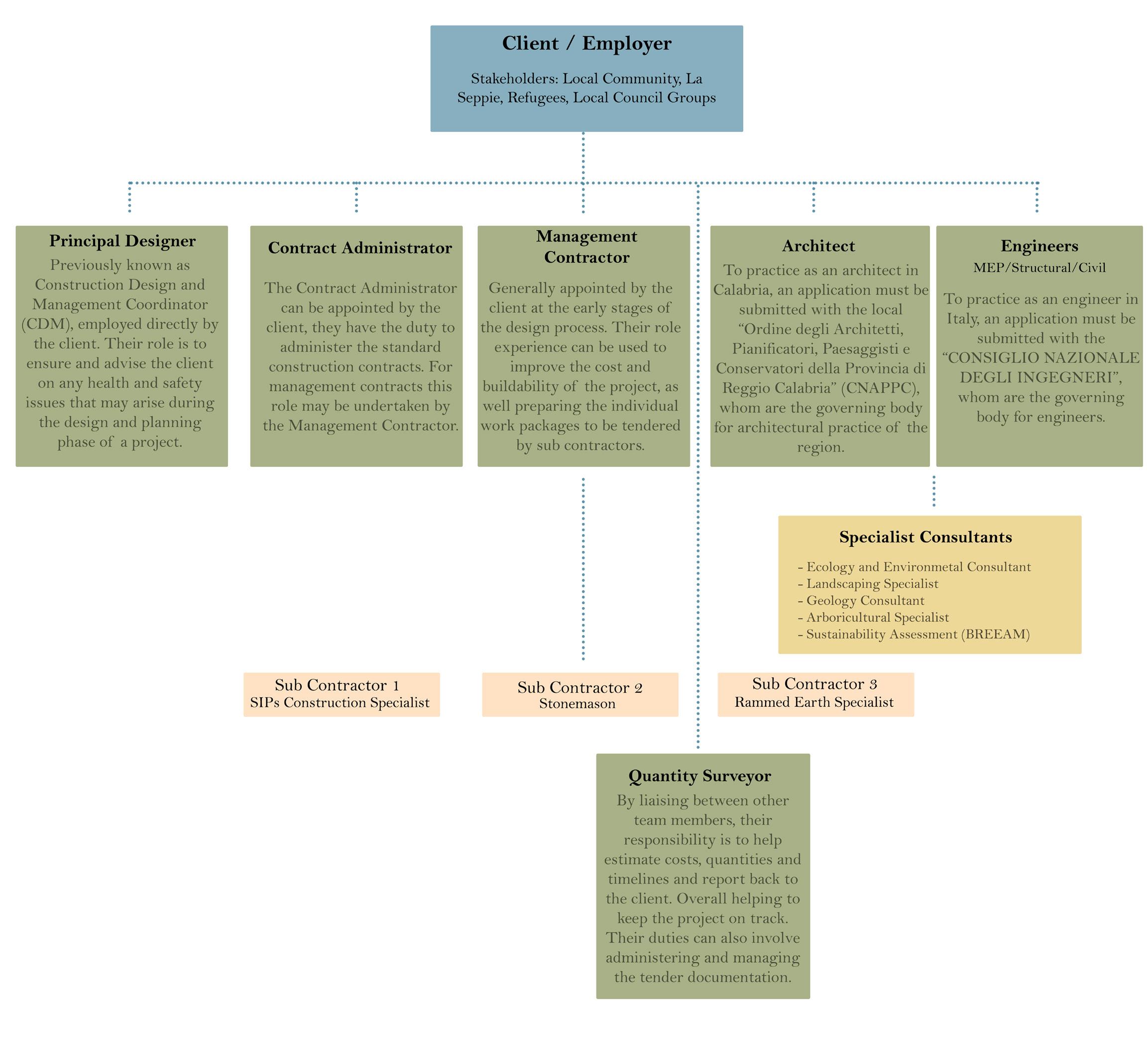
For the majority of projects the main parties involved in construction works are the client, the contractor and the designer.
ITALY
There is no formal organization within the country that produces the typical standard forms of contract that would be used on a project. On the other hand, Italy uses standards forms that have been produced by the International Federation of Consulting Engineers (FIDIC)
There are 2 main standards forms of contract/construction that area adhered to.
Design and Build Contract
This type is generally used for civil works projects, and is a project system where a sole company/contractor undertakes the role of designer and builder.
Construction Management
Under this contract the design and construction are undertaken by different entities. With the addition of civil, mechanical, electrical and plumbing also subcontracted to different parties.
THE PROJECT
Applied to the proposed project, the Construction Management contract would be considered the most appropriate. Due to the mix of different design aspects and the possibility of involving local refugees and tradesmen to help with the construction, this contract type would allow smaller portions of the work to be subcontracted to any number of trades, to help support local business and encourage community engagement with the project.
UK
There are a number of contract providers in the UK that produce readily available standard forms of contract for all types of construction projects across the UK. One of the most commonly used is The Joints Contract Tribunal (JCT) offers a range of types.
The most common building contracts used in the UK according to the RIBA are as follows:
Traditional Contract
The client appoints a designer/team to produce a set of tender documents, most commonly formed of drawings, specifications and bill of quantities. A selection of contractors are then invited to tender the project works based on the tender documents. The contractor holds no responsibility for the design.
Design and Build
With this type of contract the client can appoint a design team to prepare high level drawings, and then select a contractor to fully develop the design and construct the works. The contractor holds responsibility for the design, planning, organisation, control and construction of the works.
Management Contract
A procurement route that allows a number of different contractors to complete the works under the control of a management contractor. This type allows small portions of works to be tendered individually to specialist contractors, this can also lead to cost savings and more design flexibility.
Overview of Project Team


80 81
Funding
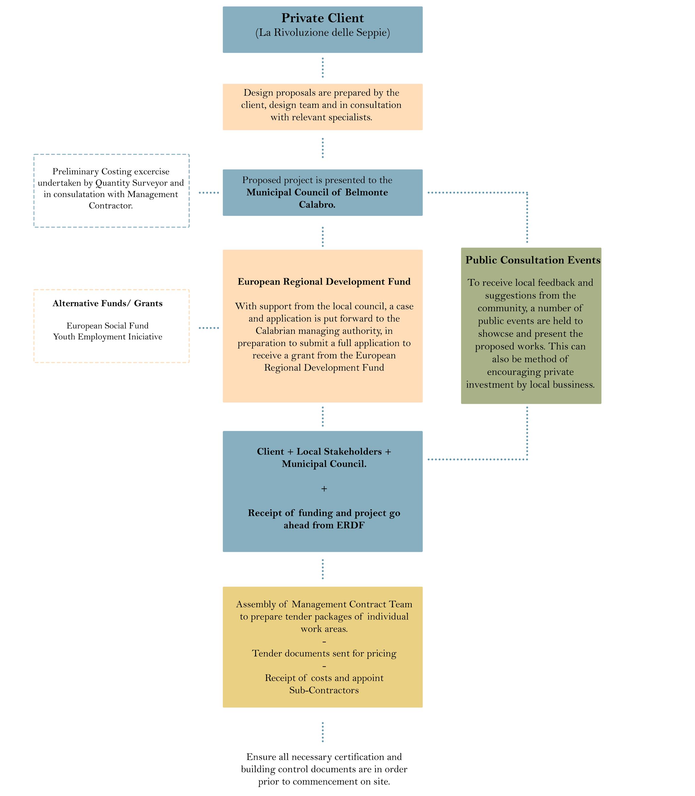
As a project that forms part of a larger regeneration scheme along the Marina, there is a number of fund resources that could be available through local consultation events and regional fund applications.
Below is a number of funding opportunities that could be explored.
EUROPEAN REGIONAL DEVELOPMENT FUNDING
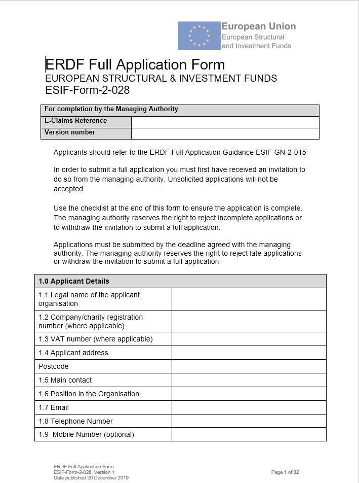
“The European Regional Development Fund (ERDF) aims to strengthen economic, social and territorial cohesion in the European Union by correcting imbalances between its regions. In 2021-2027 it will enable investments in a smarter, greener, more connected and more social Europe that is closer to its citizens.”
The ERDF hopes to prioritise investment which will encourage small business growth and create more connected communities that are lowcarbon and resilient.
To secure funding from this source, the project must have received an invitation from the managing authority. In this case an application to “The ROP Calabria ERDF” would be necessary. The project would likely develop and look to target the funding priorities of the region before any submission was made. The aim would be to make the best case possibly to increase the likelihood of receiving funding.
There are a few other funds that could potentially be explored as alternatives:
- European Social Fund


- Youth Employment Initiative. Due to the regions lowering number of young population, this funding would look to support young people living in regions with youth unemployment higher than 25%, this fund can work in conjunction with others such as the ESF above.
PRIVATE FUNDING
The project is aimed at supporting the local community and business. The creation of a new hub to draw visitors and local groups to the area. With these intentions in mind, private business cases would be put forward to local companies and business owners with the intention to generate interest in the project and encourage local investment, rather than overseas funding.
To increase interest and engage with the public, a number of consultation events would take place. The design team in conjunction with the client, would host meetings to showcase the proposals with display boards, showing renders of the project and discussing the aims looking to be achieved from the building.
These events also help to keep the community involved, recording personal views and thoughts is an important part of making sure the project is benefiting and supporting the community as a whole. By doing this exercise before a formal planning application is submitted, it is hoped any negative feedback from locals can be talked about and possible solutions found, this can help minimize the risk of future objections that could prevent planning approval.
82 83
“European Regional Development Fund” application form.
Overview of Potential Funding Strategy
Figure 55.
Applying the RIBA Plan of Work

To obtain an overall view of the project checkpoints involved, the proposals have been applied to the guidance set out in the RIBA Plan of Work 2020.
The lists shown on this page are a selection of key milestones and objectives that should be achieved at each of the project stages.
Please note the list is not limited to what is shown and is subject to additional points that can vary from project to project.
0. STRATEGIC DEFINITION
- The Architect can initiate discussions with the client to understand the requirements and business case put forward
1. PREPARATION AND BRIEF
- The project brief and exemplary precedence is agreed with the client and site surveys can begin to take place.
- Key survey information required: Structural assessment of existing foundations, historical building information of the Marina.
- Pre-Planning application advice would be beneficial to understand the councils local planning requirements.
- Outline procurement route can be started, possible funding sources.
- Appoint design team.
2. CONCEPT DESIGN
- Initial concept sketches based on clients precedent, business model and brief can be approved.
- Based on Pre-Application advice, initial concepts along with outline specification and costs can be submitted to Municipal Council of Belmonte for review.
- Consultation with locals and stakeholders can take place.
- Potential outline planning with some matters reserved.


- With a Management Contract procurement route, the main contractor could be appointed at this stage.
3. SPATIAL COORDINATION
- Full coordination of Architectural and Engineers designs.
- Cost guidance is also to be updated in accordance with updated outline project specifications.
The RIBA has also developed an overlay to the Plan of Work called the DfMA. The Design for Manufacture and Assembly, aims to encourage new modern methods of construction to create a limited selection of standardised components, that can be efficiently manufactured off site, trasnported to site and put together safely and more rapidly.


There is potential for this process to be used on the modern air tight SIPs pods.
- For this particular site, preliminary site visits would be beneficial to understand the viability in preparation for the brief.
- Review the project risks and budget resources.
- Verify the performance of the building post occupancy.
- Update any building information in the Health and Safety File and Fire Safety information.
- Potential adaptation of building after life use/cycle. Remodelling or Demolition, this would go back to Stage 0.
5. MANUFACTURING AND CONSTRUCTION
- Preparation of required information for a formal Full Planning Submissions.
- Review designs against Building Regulations.
- Receive necessary site surveys to satisfy any additional planning requirements.
4. TECHNICAL DESIGN
- Due to the contract type, individual works tender packages can be prepared to send out to specialist sub contractors.
- All necessary specification should be prepared to allow an accurate tender pricing.
- Submission of Building Control application to regions statutory body.
- Discharge of any pre-commencement planning conditions.
- Develop project programme.
- Client to be in receipt of all Health and Safety Files, Building Manual and Fire Safety Information.
-The contractors are to rectify any defects that may occur and an overall inspection of construction quality undertaken.
- Comply and sign off any outstanding planning conditions.
- Undertake any building performance evaluations such as BREEAM.
- Manufacturing of pre-fabricated SIPs pods.
- Construction plan for rammed earth walls. Local rammed earth specialists and preparation for public engagement events. This would require Health & Safety risks assessments and sign off before any public is allowed onto site.
- Preparation of building manual for natural ventilation strategy and all other building services.
84 85
6. HANDOVER
7. USE
Figure 56.
Figure 57.
Design Statement


Cultural Context
The proposed site is located in the Marina di Belmonte, a town stretched along the shoreline of the Tyrrhenian Sea, on the South-Western coast of Italy. In close proximity to the neighbouring hilltop town of Belmonte Calabro. Much like many of the surrounding southern regions, over the past years it has seen a large proportion of the younger population moving away from the small towns, in pursuit of higher education or job opportunities that the large northern cities such as Naples can offer. However, these areas have seen a rich influx in numerous African migrants groups in search of a better quality of life, improved education and intern have helped create a diverse community along the coastal towns.
The Studio 3 project seeks to respond to the local needs but also bring people together, by creating environments for future living and working within urban and rural settings. The proposal is focused on regenerating and redefining derelict areas of the town. Selecting pockets of land that have fallen out of use, with the aim of introducing new purpose built community hubs for hybrid working and living, that in the recent ongoing pandemic has quickly become the normality for many people.
The deep heritage and tradition of Italian cuisine, socialising and music is something that Belmonte Calabro portrays very well. Bringing people together through celebrations and festivals are a yearly occurrence. The proposed building will feature design elements that hope to encourage locals and visitors to interact and absorb their traditions. A new communal Piazza with outdoor dining table will be used as canvas to encourage people to connect and engage, and the isolated living pods will provide temporary accommodation to passing visitors and walking groups.
The Marina di Belmonte is characterised by a much more suburban layout, compared to the hilltop village of Belmonte Calabro. Ease of access to local shops, restaurants and good connections to major road networks and train lines allow a fluent journeys between the nearby towns.
Environment, Services & Energy
Belmonte is located in the Mediterranean climate zone, characterised by a high contrast between winter and summer temperatures (8 to 30 degrees). Due to the proximity to the coast, the Marina is subject to a prevailing West wind and drastic changes in temperature. A number of key design elements will make the most of onsite conditions and contribute to the overall building sustainability and create secure places for social interaction. To make the most of the constant sea breeze, the internal space layout has been designed for a stack ventilation strategy, drawing air from the base of the building to the top by natural drawn airflow, reducing mechanical vents.
Internal isolated living pods located on the first floor, will be pre-fabricated off site and assembled upon arrival. Fully insulated with rigid insulation and airtight seals, the SIPs panel pods will provide a passive heated space, that can be naturally cooled using the fresh air from the stack ventilation proceeding from the ground floor.
With the site susceptible to flooding, raising the living accommodation above the ground will remove any potential flooding risk. External Sustainable drainage systems will also provide additional flood control from new greywater and rainwater discharges from the building and site. In order to reduce the CO 2 emissions, the majority of the buildings external wall construction uses 500mm thick rammed earth, inherently dense and with good thermal properties, this local resource will help regulate the internal temperature by its high heat capacity. A bespoke brise soleil will protect glass rich elevations from excess of solar and heat gain.
A new planting scheme with local plant and tree species will encourage biodiversity to the site and provide open natural spaces, linked to improving residents well-being and reducing overall stress, providing a space to socialise and relax.
Structures, Materials & Construction

Taking advantage of the easy access to the site and local resources, material selection has been carefully considered with the use of local resources wherever possible. A traditional method of construction from the area - “Adobe” - consisting of mixing the regions fine grain earth and local straw“vreisti “- is an ideal construction material. Not only due to local sourcing but also the fact that local skilled workers, along with apprentice migrants, could be involved in the overall construction forming a new link between the contractor and community.
The local quarry in Pietra di San Lucido, is a source for the natural limestone that will be used for the external cladding on the ground floor concrete walls. Due to its close proximity to site, minimal transportation will be required, with an approximate carbon emission output of 2.12 kg per tonne extracted. The use of durable concrete for the ground floor walls will help provide flood resistance, with a longer life span and weatherproof qualities. To balance the use of new concrete fabrication, the existing concrete foundations on site will be reused after the relevant testing has been done to certify their viability and strength. The SIP’s panels used on the living pods are to pre-fabricated off site, helping to reduce on-site workforce and minimise delays. There will be various methods of construction on site and off site. Firstly the ground concrete walls are to be poured in-situ by specialist contractor, followed by shuttering ready for the rammed earth wall construction. This is to be the slowest part of project due to local material sourcing and weather dependence. Local trades and migrants could also get involved to learn hands on experience at this stage. During this period the SIPs living pods are to be constructed off-site, ready to be transported on site once the rammed earth walls are completed, and then assembled.
Management, Practice & Law
The preferred method for procurement will be a Management Contract, managed by a management contractor appointed by the client, this allows small packages of work to be tendered by specialist sub contractors, that can include local skilled workers. This would be beneficial so that it allows each specialised contractor to undertake their own package of work and therefore assume the sole responsibility. It can be more cost effective due to individually priced packages and it can lead to a more flexible contract.
The Management Contractor, appointed by the client, is generally brought into the design as early as possible ( Stage 3) to help with design and specification, while the Architect (design team) will develop the proposals from the client brief (Stage 0). Both design team and management contractor will work alongside until project handover (Stage 6)
The general responsibilities for the architect will be to liaise with the client and consult with the necessary specialist, developing the design in-line with the project brief. There may also be the need to act as client representative under certain circumstances for statutory applications and during discussions with contractors. The proposed design will follow building regulations and consider local views, through wide community consultation to ensure the project is built to meet local needs and requirements. The project will look to be funded by the European Regional Development Fund and potential Youth Funding Schemes for migrant workers, with support from the local council and private stakeholders.
The procurement aims to provide new work facilities and important employment roles, both during the construction period and post completion. Prior to commencement on site and to help reduce unforeseen delays, consultation will be undertaken with local professionals who have prior knowledge of climate, arboriculture, ecology, and geology of the site.
The project will also follow statutory requirements and submit local building permits when needed, as well as adhering to Health and Safety, Building Regulations and Sustainability guidelines.
86 87
Precedence - Courtyard Spaces
TASK


With a similar toolkit as the first brief and a new architectural typology the “courtyard”, the aim is to scale up from a house for a friend and family, to a much larger proposal, encouraging social and work-related gatherings.

Develop an understanding of how the repetition of these new social centres along the coast could benefit the overall neighbourhood, improve educations skills and promote local industry.
The first task was to select a number of new precedence, chosen not only for their construction methods but their social and community engagement throughout the procurement.
Precedent 1 - Simul et Singulis
Location: Cologne, Germany
Architects: Orizzontale
Features of interest:
The proposed intervention takes over an abandoned archway underneath a railway, the temporary structure was constructed with the help of local inhabits. Sparking a public reactivation through the space.

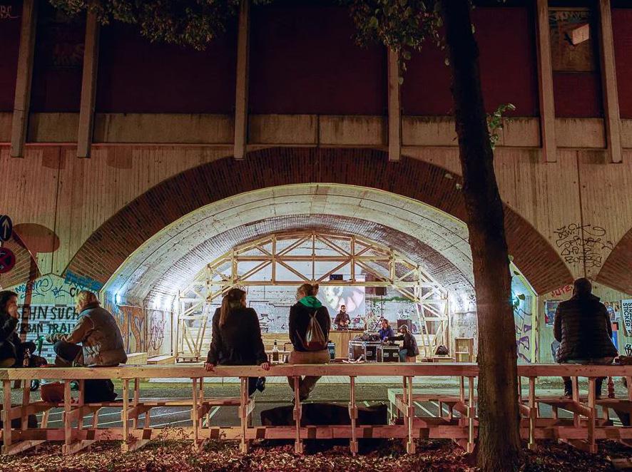
- Community space for meetings and seminars.

Precedent 2 - Gallery of Archive
Location: Ramsgate Royal Harbour
Architects: Haptic Architetcs

Features of interest:
The project provides a place for communal get reunion, a home-store and kitchen create great opportunities for local business. Redevelopment of an abandoned archway
The new community hubs would be located in areas along the Marina that have become abandoned or unused, purposefully reusing empty plots of land. The programme for a new “Marina Food Festival” will allow neighbourhoods to share different foods, ideas and life stories. An array of neighbourhood dining hubs would be located along the Marina, encouraging visitors and locals to explore the town and local cuisine.
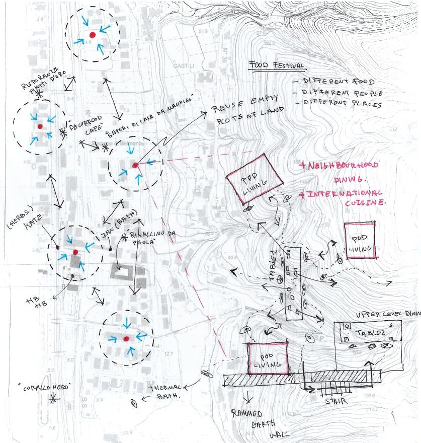
88 89 Brief 02
Figure 59. Isometric sketch and Internal view of “Gallery of Archive”
Figure 58. Axonometric process drawing and night scene of finished project.
Sketch 15. Sketch diagram of new neighbourhood dining hubs along the Marina.
Developing the Brief
A starting point to developing the new community neighbourhood brief, was using the precedent buildings. Research into the initial client and design team intentions was a good place to start. A list below of particular design aspects and social intentions, providing a brief overview of what the future project would look to embrace in the design.

- Retail and communal gathering space around a large table.


- Separate seating areas provides a diverse and interesting layout. Allowing people to linger and gather in a variety of areas within a small space.
- The spaces are developed with flexibility in mind, movable seating and adjustable furniture allow for a flexible change of use to cater for different social gatherings or exhibitions.
By combining a number of the design elements from the precedent buildings and the first project, a number of design scenarios were sketched out. All feature the following design elements, that can be adapted dependent on site area and conditions.
1. Central Eating and dining table to encourage communal eating and social interaction.
2. Pre-fabricated pods that can host local trades and pop up bussines, providing an opportunity for people to experience new cuisine or culture of the region.
3. Temporary residency will provided by individual living pods, using similar construction techniques to the first project.
4. Additional areas of seating and flexible spaces will allow users to freely adapt their environment to suit comfort and wellbeing.

90 91
Sketch 16. Sketch of mountain community hub with raised platforms to support the pods.
Sketch 17. New community hubs will look to encourage local communities to visit the Marina, through food and events.
SITE PROPOSALS - A New Gateway to the Beach-front
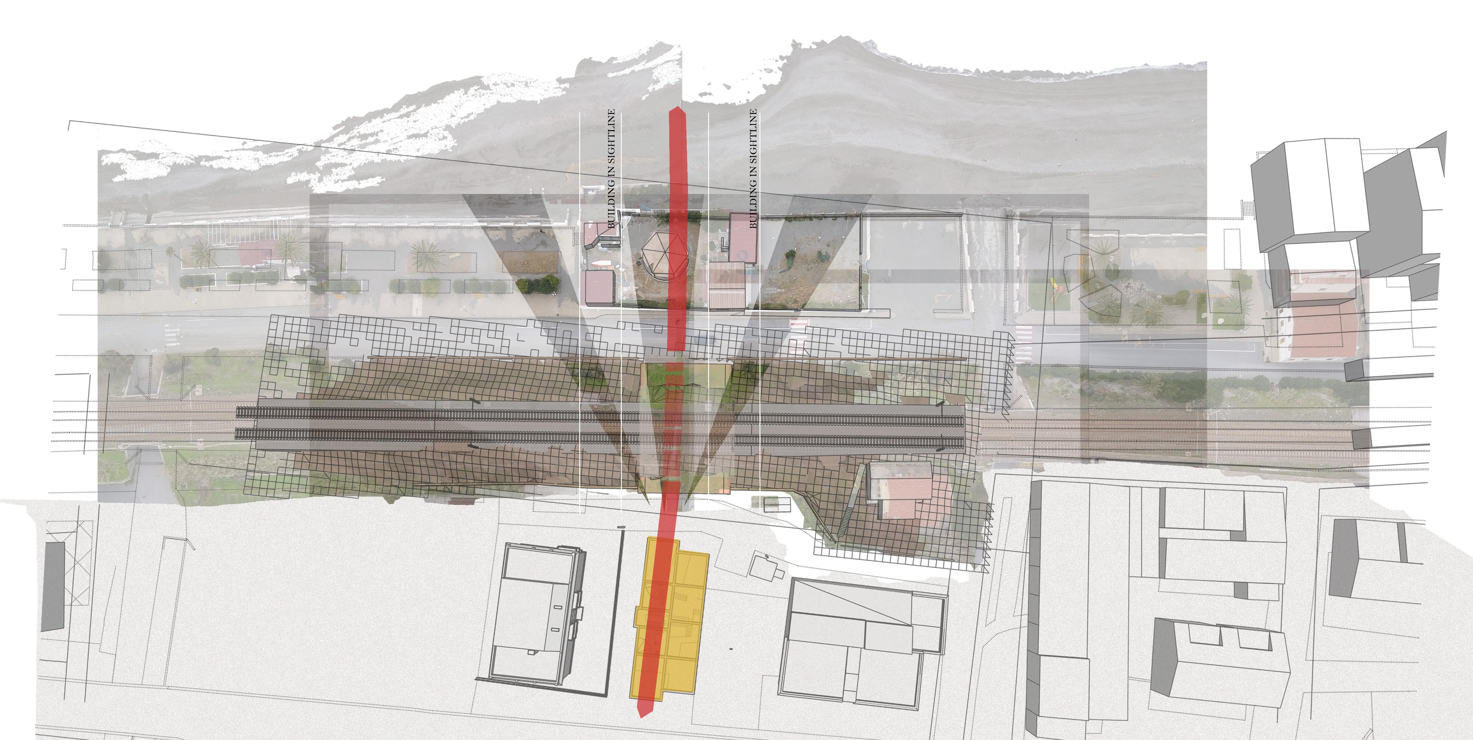


An up scaling of the original proposals on site, will see the creation of a new pedestrian connection route to the beachfront underneath the railway. Although the Marina already has many routes to the beach, these are mainly vehicular, therefore the proposal is to create a new “Avenue” that is for pedestrians only.
The new pedestrian undercroft will also bring new sight-lines and views to the site, drawing people from the more urban area of the Marina, under the railway, and to the beachfront of the Tyrrehenian Sea.
92 93
NEW AVENUE
DESIGN CONCEPT - Raising the building
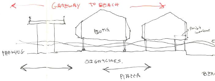


After a number of sketches an outline for the overall scheme brief had be formed. The proposals would be formed of two key elements that in conjunction would lead to the new community dining hubs.
1. An larger rammed earth building will still be host to visitors and locals, but will also take on the role of providing a space for future traders, both local and visiting, to socialise and rest.
2. A new pedestrian undercroft located underneath the railway, is to provide a new central dining space that incorporates a number of new workshop spaces. These are to be pre-fabricated using the same methods as the internal living pods.

RAISED BUILDING
A number of key design factors meant the existing rammed earth building, along with the internal living pods, would now be elevated off the ground, sitting on slender columns:
1. The new pedestrian avenue circulates underneath the building, approached from the centre of the Marina, this aims to draw people into the site and out onto the beach front.
2. With the inherent site flood risk, elevating the entire building off the ground removes the need for a sacrificial floor, and additional services protection from water.
94 95
Sketch 18. Axonometric concept sketch for new community dining hub.
Sketch 19.
Top: Raised buildings to create increased flow.
Above: Overall site plan sketch of building elements.
FUTURE VISION OF MARINA COMMUNITY HUB

New community hub that will play a central role in creating new relations through local food. Defined by a paved pathway that draws visitors down to the beachfront, the journey will start by walking under the accommodation pods, small suspended spaces that are designed to be simple and efficient in their layout, leading down to the under croft shelter under the railway, this shaded area plays centre stage for pop up workshops to teach local cuisine recipes, such as pasta, spicy Nduja sausage or sweet fig treats. A new piazza next to the accommodation pods, will be a landscaped area formed of a combination of plants and movable seating areas.
CONCLUSION

This sketch was chosen to set the overall project scene, in preparation to move forward and develop the proposals to a more advanced stage. Including the evolution of the structural and construction strategy and technical design.

96 97
Bibliography and References
Bibliography
Cultural Context
ArchDaily. 2022. Archive – Homestore & Kitchen / Haptic Architects. [online] Available at: <https://www.archdaily.com/779999/archive-nil-homestore-and-kitchen-haptic-architects> [Accessed 24 November 2021].
ArchDaily. 2022. Machiya in Kawagoe House / K+S Architects. [online] Available at: <https://www.archdaily.com/940335/machiya-in-kawagoe-house-k-plus-s-architects> [Accessed 12 October 2020].
En.climate-data.org. 2022. Belmonte Calabro climate: Average Temperature, weather by month, Belmonte Calabro water temperatureClimate-Data.org. [online] Available at: <https://en.climate-data.org/europe/italy/ calabria/belmonte-calabro-114599/> [Accessed 19 December 2021].
Mairs, J., 2022. Skinny dwelling between two existing houses | Dezeen. [online] Dezeen. Available at: <https://www.dezeen.com/2015/07/02/josep-ferrando-slots-skinny-residence-between-walls-two-existinghouses-sant-cugat-spain-catalonia/> [Accessed 12 October 2020].
Orizzontale. 2022. Simul et Singulis (Cityleaks Festival 2019). [online] Available at: <https://www.orizzontale.org/en/portfolio_page/simul-et-singulis-be-together-and-be-oneself/> [Accessed 24 November 2021].
“Statistiche DemograficheComune Di BELMONTE CALABRO, Densità ...”, n.d. Accessed March 7, 2022. https://ugeo.urbistat.com/ AdminStat/it/it/demografia/dati-sintesi/belmonte-calabro/78013/4. [Accessed 17 December 2021].
Environment, Services & Energy
“Ambiente - Comune Di Belmonte Calabro”. 2022. Comune.Belmontecalabro.Cs.It. http://www.comune.belmontecalabro.cs.it/index. php?action=index&p=337. [Accessed 11 January 2022]
“How BREEAM Certification Works | BREEAM - Sustainability Assessment Method”. 2022. BREEAM - Sustainability Assessment Method |. https://www.breeam.com/discover/how-breeam-certification-works/. [Accessed 14 January 2022]
“Sustainability Benefits Of Concrete : GCCA”. 2022. GCCA. https://gccassociation.org/sustainability-benefits-ofconcrete/#:~:text=Concrete%20has%20excellent%20 sustainability%20qualities,GCCA%20in%20Numbers%2C%20 2020).&text=Concrete%20can%20also%20 be%20reused,of%20life%20is%20100%25%20recyclable. [Accessed 9 January 2022]
“Sustainable Building With Sips”. 2022. Sips.Org. https://www.sips.org/resources/sustainability. [Accessed 13 January 2022]
Heywood, H., 2021. 101 Rules of thumb for low energy architecture. [S.l.]: RIBA Pubns. Ltd. (Book)
“What Is Natural Ventilation? | Ventive”. 2022. Ventive. https://ventive.co.uk/resources/natural-ventilation/#:~:text=Natural%20 ventilation%20is%20a%20 method,Reduces%20carbon%20emissions. [Accessed 13 January 2022]
2022. Architecture.Com. https://www.architecture.com/-/media/GatherContent/Test-resources-page/Additional-Documents/ RIBASustainableOutcomesGuide2019pdf.pdf. [Accessed 15 January 2022]
2022. https://www.netregs.org.uk/environmental-topics/waste/waste-treatment-processes/recycling- concrete/#:~:text=You%20 can%20recycle%20concrete%20and,care%20will%20apply%20to%20it. [Accessed 9 January 2022]
Materials, Structures and Construction
“A Brief Guide to Calculating Embodied Carbon”, n.d. Accessed March 7, 2022. https://www.istructe.org/IStructE/media/ Public/TSE-Archive/2020/A-brief-guide-to-calculating-embodied-carbon.pdf. [Accessed 27 February 2022]
“Six Benefits Of Offsite Construction”. 2022. Offsitehub.Co.Uk. https://www.offsitehub.co.uk/industry-news/news/six-benefitsof-offsite-construction/. [Accessed 9 January 2022]
“U-Values - Designing Buildings”, n.d. Accessed March 7, 2022. https://www.designingbuildings.co.uk/wiki/U-values. [Accessed 2 March 2022]
“What Are Sips”. 2022. Sips.Org. https://www.sips.org/what-are-sips. [Accessed 23 January 2022]
2022. Flore.Unifi.It. https://flore.unifi.it/retrieve/handle/2158/827275/27383/TERRA%20EUROPAE_Earthen%20. [Accessed 8 January 2022]


2022. https://assets.publishing.service.gov.uk/government/uploads/system/uploads/attachment_data/file/540328/ BR_PDF_ AD_L2A_2013_with_2016_amendments.pdf. [Accessed 22 January 2022]
2022. https://www.designcurial.com/news/rammed-earth-building-material-past-present-future7896641/#:~:text=Rammed%20earth%20is%20highly%20sustainable,material%20is%20already%20on%20site. [Accessed 13 January 2022]
2022. http://www.uni-terra.org/bauhaus-universitaet-weimar/rammed-earth-walls-moisture-transfer-and-change-in- strength. [Accessed 23 January 2022]

Management, Practice and Law
“Design and build procurement route.” Designing Buildings. Accessed 7 March 2022. https://www.designingbuildings.co.uk/ wiki/Design_and_build_procurement_route. [Accessed 6 February 2022]
“DfMA Overlay to the Plan of Work”, n.d. 2022. https://www.architecture.com/knowledge-and-resources/resources-landingpage/dfma-overlay-to-the-riba-plan-of-work. [Accessed 17 February 2022]
“European Regional Development Fund.” European Commission | Choose your language | Choisir une langue | Wählen Sie eine Sprache. Accessed 7 March 2022. https://ec.europa.eu/regional_policy/en/funding/erdf/#1. [Accessed 10 February 2022]
“Management contractor.” Designing Buildings. Accessed 7 March 2022. https://www.designingbuildings.co.uk/wiki/ Management_contractor. [Accessed 13 February 2022]
“Ordine degli architetti di Reggio Calabria.” Ordine degli architetti di Reggio Calabria. Accessed 7 March 2022. https://www. oappcrc.it/. [Accessed 15 February 2022]
“Piano Strutturale Associato - Comune Di Belmonte Calabro”. 2022. Comune.Belmontecalabro.Cs.It. http://comune. belmontecalabro.cs.it/index.php?action=index&p=704. [Accessed 2 February 2022]
“Realworld Law.” General construction law in Italy - DLA Piper REALWORLD. 2022. https://www.dlapiperrealworld.com/law/ index.html?t=construction&s=forms-of-contract-procurement-+methods&c=IT. [Accessed 4 February 2022]
“RIBA Plan of Work”, n.d. Accessed March 7, 2022. https://www.architecture.com/knowledge-and-resources/resourceslanding-page/riba-plan-of-work.
98 99
References
• Figure 4 : Images of Sketching in Belmonte. Courtesy of La Rivoluzzione delle Seppie. Image Source: https://arte.sky.it/news/ belmonte-calabro-south-learning-architettura
• Figure 9: Images of Kawagoe House . Courtesy of: Hiroshi Ueda. Image Source: <https://www.archdaily.com/940335/machiyain-kawagoe-house-k-plus-s-architects>
• Figure 10, 11, 12, 13 : Images of House 176 E+M . Courtesy of Josep Ferrando Architecture at Bailen 232 bis 1D 08037 Barcelona
• Figure 17: Images of Online tutorial session Courtesy of: Myles Albon-Crouch
• Figure 36: RIBA Sustainable Outcomes Guide. Image Source: https://www.architecture.com/knowledge-and-resources/ resources-landing-page/sustainable-outcomes-guide
• Figure 38: HR Government Building Regulations Park L2A. Image Source: https://www.gov.uk/government/collections/ approved-documents
• Figure 50: Image of Futurebuild exhibition stand. Image Source: https://www.rainwaterharvesting.co.uk/exhibitions/
• Figure 52: Cover image of Regolamento Edilizio ed Urbanistico . Image Source: http://comune.belmontecalabro.cs.it/index. php?action=index&p=704
• Figure 53: Cover image of “The London Plan” . Image Source: https://www.london.gov.uk/sites/default/files/the_london_ plan_2021.pdf
• Figure 54: Extract from ”Piano Strutturale in forma associata” . Image Source: http://www.comune.belmontecalabro.cs.it/index. php?action=index&p=704
• Figure 55: Application form ERDF . Image Source: https://www.gov.uk/government/publications/european-regionaldevelopment-fund-full-application
• Figure 56 and 57: RIBA plan of work and DfMA overlay logos. Image Source: https://www.architecture.com/knowledge-andresources/resources-landing-page/dfma-overlay-to-the-riba-plan-of-work
• Figure 58 : Images of Simul et Signulis. Available at https://www.orizzontale.org/en/portfolio_page/simul-et-singulis-betogether-and-be-oneself/
• Figure 59 : Images of Archive Gallery . Available at https://www.archdaily.com/779999/archive-nil-homestore-and-kitchenhaptic-architects/568db9bce58ece2d3c0006ad-archive-nil-homestore-and-kitchen-haptic-architects-photo?next_project=no

( All images and sketches not credited belong to the author.)

100 101
Brief 01 Brief 02


