W H I T E P A P E R


L O W C H A R G E A M M O N I A S Y S T E M S D E
S I G N E D A S D I R E C T E X P A N S I O N

Introduction Low Charge DX system Evaporator Design Liquid Distribution Thermodynamics Vapor Quality Sensor Cold store in Melbourne, Bidvest, Truganina Idea For Further Simplification And Charge Reduction Conclusion 01 02 03 04 05 07 08 09 TABLE OF CONTENTS
INTRODUCTION
The vapor quality sensor has been on the market since 2014 The majority of sensors are used on DX Ammonia systems, where it improves the efficiency to a level equal or better than overfeed systems. Requirements to reduce global warming (GWP) and CO2 emissions lead to an increased desire for use of natural refrigerants. It is now possible to design Ultra Low Charge dry expansion systems, safer and more energy efficient than conventional DX, flooded, and pump circulation systems
The paper describes key functions, components, and 6 years of experience with operation of Low Charge Ammonia Cold Stores in Australia, with focus on the evaporator control and a new concept for defrost control

LOW CHARGE DX-SYSTEM
Experience gathered from several Low Charge Ammonia DX systems installed in Australia, shows that the systems with Vapor Quality measurement/control are more energy efficient and they don't have the same pressure variations of the same magnitude as DX-systems based on superheat control.
Controlling DX Ammonia systems.
For many years DX control of ammonia systems has been difficult and led to inefficient systems, often due to challenges with watier. The presence of even small amounts of water in ammonia has a significant negative effect on DX evaporator performance (Nelson 2010)
For example, the water content of about 1% in the ammonia will lead to an increase in the boiling point towards the end of the evaporation process of 5 6K in low temperature evaporators. The use of superheat based injection control would not be able to differentiate between superheat and a boiling point increase caused by water This situation may result in liquid flood back from the evaporator to the compressor
The refrigeration industry has thus far attempted to solve this problem by using pump circulation, or liquid overfeed A pump circulation system circulates a quantity of refrigerant, that is several times larger than that evaporated in the evaporator This eliminates a large part of the effect of the boiling point increase The disadvantages are an increase in refrigerant charge and inventory increased pressure loss in the wet suction line, riser piping, increased energy consumption, and lack of freezing capacity
EVAPORATOR DESIGN

The evaporator is a major component in a refrigeration system. For the evaporator to work optimally with Ammonia as a refrigerant, is it necessary to design it, especially for lowtemperature operation.
Ammonia's very high latent heat of vaporization means that the amount of the circulating refrigerant is small, which increases the requirement for the expansion valve, liquid distribution, and the evaporator design.
In general, dry-expansion evaporator design requires that users are perfectly aware of the capacity range within which the evaporator will be used These considerations are also important for evaporators that are installed for pump circulation, but the consequences of an incorrect number of channels are easier to compensate for in a pump circulation system, than in a dry expansion system with a limited refrigerant charge.
In a dry-expansion system (especially using ammonia as the refrigerant) the choice of the evaporator tube diameter is of great importance. For evaporators with small capacities, the distribution of refrigerant can also result in difficulties simply because the distributor tube, capillary/venturi diameters become so small that commercially available pipe material is not available, impurities can also block the capillary tube, thereby reducing the active evaporator area.
Other fluid distribution systems that work by the gravity principle are good alternatives (tank distributors such as Küba or Colmac Coil).
It is not possible to generalise regarding the optimal average vapour velocity in the evaporator. Small pipes will have acceptable results with lower vapour velocity than larger pipes. Pipes with internal surface enhancements would also yield acceptable results with lower vapour velocity than smooth pipes. In general, dry expansion evaporators are designed for a substantially higher refrigerant pressure drop than pump circulation evaporators. To avoid this pressure drop resulting in a reduction of the logarithmic temperature difference, it is often necessary to use innovative evaporator circulation methods/designs such as physical parallel flow (thermodynamic counterflow), consideration of the possible effect of gravity on the evaporator function, oil accumulation, sensor placement, etc.
Figure 1: Evaporator tubes with Inner grooved surface
EVAPORATOR DESIGN
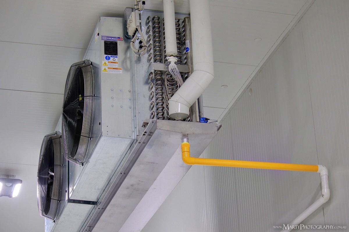
Experience from the Bidvest plant in Melbourne has shown a very low “EDT” (equivalent dry-bulb temperature) of only 2.3K during start-up (fan speed only 60%). The air-cooler was a Colmac Coil DX aluminum with inner-grooved tubes, controlled by an HBX-DX Vapor Quality sensor.

In general, dry-expansion evaporator design requires that users are perfectly aware of the capacity range within which the evaporator will be used These considerations are also important for evaporators that are installed for pump circulation, but the consequences of an incorrect number of channels are easier to compensate for in a pump circulation system than in a dry expansion system with a limited refrigerant charge.
Evaporator design with Inner-grooved aluminum tubes or internal spiral will improve the heat transfer performance.
Very high heat transfer
Easy to form and bend
Note: Evaporators with internal groves are very sensitive to oil film, Which means a good oil separation is needed
▪
▪
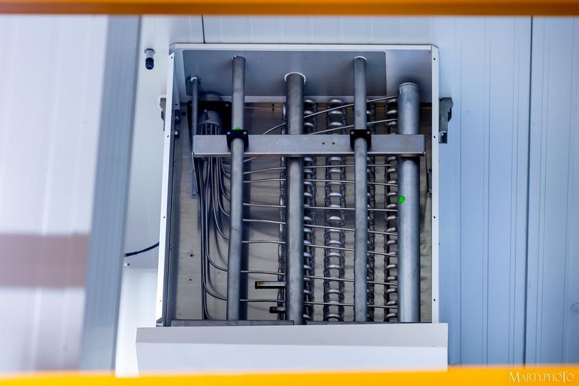
LIQUID DISTRIBUTION
The distribution of ammonia in DX systems is often difficult, simply because flashing of the refrigerant will cause a two-phase flow in the distributor system. In these situations, other distributor types must often be used, instead of the conventional capillary/venturi type distributors. Tank distributors working by gravity have been found to work well with ammonia. These will also optimize the distribution of other types of refrigerants, especially at part load.


Figure 2: Venturi VS Küba Cal liquid distribution (Kelvion/Küba)
DX
Figure
3:
evaporator with tank distributer and Vapor Quality Sensor
THERMODYNAMICS

Parameters that influence the two-phase flow pattern and have strong impact on the heat transfer: In thermodynamics, Vapor Quality is the mass fraction between vapor and liquid in a saturated wet mixture, i.e. dry vapor has a quality of 1.0, and pure liquid has a quality of 0.0, Quality “X” can be calculated by dividing the mass of the vapor by the mass of the total mixture.

In dry expansion systems (DX) a part of the heat exchanger area is used to secure dry vapor. Further tube length/area is added to obtain Super-heating of the vapor. In this area, the heat transfer is very low. In liquid overfeed system, with flooded evaporators, the refrigerant is not boiling completely. Too much refrigerant will limit evaporation as the boiling is performed as bubbly and plug flow, This is characterized by heat transfer coefficients compared with the heat transfer coefficient that can be achieved during boiling flow in semi-flooded evaporators.

Flow Patterns and heat transfer Coefficient ”β”
Figure 4: Measuring ranges DX shown in h log P diagram
A normal two-phase flow pattern is a subjective observation, and there is no general assessing method, that identifies and describes flow patterns precisely. The vapor quality sensor, however, is able to measure both the Vapor Quality/Liquid Ratio and flow pattern by using a Vapor Quality Sensor in the evaporator pipe. The sensor is normally installed in the outlet of the evaporator for controlling the liquid supply relative to the heat load.
The semi-flooded operation ensures a much more balanced system with minimum variation of pressure and very low Super-heat from 0.5 to 1.0K. The semi-flooded operation ensures maximum efficiency as 98% of the evaporator surface is wet.
Figure 6: Capacitance VS different flow patterns

Figure 6 shows how the capacitance varies for different flow patterns. (Measurements made by Gent University in Belgium). For two-phase flows, the dielectric constant of both phases strongly influences the measured capacity (De Kerpel, 2013).
Optimum efficiency is achieved by measuring the Vapor Quality (X-value) at the evaporator outlet and controlling the liquid feed to the evaporator according to the Vapor Quality signal. The time-based flow pattern shows that by measuring the vapor quality it is possible to measure and regulate liquid feed depending on the evaporator load to obtain an optimal and homogenous flow pattern. The sensor signal is a mirror image of the current flow pattern inside the piping. As an example, it is possible to measure if the evaporator is overfeeding or with non-uniform liquid flow distribution. Slug and intermittent flow with short intervals indicate overfeeding, while an unstable flow pattern as slug flow with long intervals indicates a non-uniform refrigerant supply, whereas a stable signal indicates homogenous flow.
THERMODYNAMICS
The sensor is based on the capacitive measurement principle, in which two or more measuring electrodes/conductors measure the Vapor Quality as a change in electrical field/resistance, depending on the difference in the dielectric properties named “dielectric constant” according to the ratio between vapor and liquid. Measuring is instantaneous, i.e., without delay.

The result is a very safe measuring system with 100% repeatability with a direct link to the chemical formula. Compared to control based on temperature and pressure measurement, the Vapor Quality measurement based on the capacitive principle is a more direct and stable measurement of the two-phase flow of the fluid in the outlet of evaporators and liquid separators.

Figure 7: Capacitance principle
COLD STORE IN MELBOURNE, BIDVEST, TRUGANINA
Freezing: 3 DX evaporators 31°C/ 24°F evaporating temperature, unit refrigeration capacity approx 60kW, refrigerant operating charge of 1 42kg/3lb per evaporator Medium temperature: 1 DX evaporator 3°C/26 6°F evaporating temperature, refrigeration capacity approx.37W, refrigerant operating charge 2.5kg/5lb.
Anteroom: 2 DX evaporators, evaporating temperature 3°C/26 6°F, unit refrigeration capacity approx. 58kW, refrigerant operating charge 4.4kg/9lb per evaporator.
The main points regarding the implementation of the system in Melbourne are:
▪
Use of aluminum evaporators with tank distributors and internal surface enhancement in low temperature evaporators.
▪ Use of piston compressors with very low oil carry over (<3 ppm at the design point less at reduced rotational speed)
▪ Frequency converters on all compressors and fan motors
▪ The possibility of switching between superheat based refrigerant injection control and gas quality based injection control
▪ Oversized evaporative condenser with Stainless steel tubes
▪ Use of internally smooth stainless steel pipes for all interconnecting refrigerant pipelines
▪ High pressure float control between the condenser and the intercooler
▪ Return of the condensate formed during hot gas defrost directly to the intercooler, using a high pressure float and dedicated condensate return lines
▪ Two hot gas solenoid valves for each evaporator enabling warming of the drain pan prior to defrosting the evaporator coil
▪ Desiccant dryer in the freezer, which distributes the dry air to the doors using air distribution ducts
▪ Automatic evaporator fan speed control optimized based on the entering temperature difference between the air and ammonia for the individual evaporator
▪ Possibility of regulating the cold store temperature directly using compressor capacity modulation
▪ System refrigerant charge, 480 kg low temperature capacity approx 177kW, high temperature capacity approx 140kW, total volume facility approx 42,600 m³, estimated yearly specific energy consumption 22 26kWh/m³*a
COLD STORE IN MELBOURNE, BIDVEST, TRUGANINA

Operating experience
More than 6 years of experience have proven that the Low Charge Ammonia DX central system works well, it is very stable with much lower energy consumption and maintenance Daily work is reduced compared to a similar pump circulation system.
Control of the system requires that you regulate all parameters slowly as changes in capacity will affect the pressure, and have a great influence on the balance in the system, as well as the safety of operation Opening and closing times of the expansion valve must be slow as the time for the refrigerant to pass through the evaporator tubes is long, 20 to 30 minutes has proven to work well. After defrosting the Vapor Quality Sensor element is wet, and it requires that the sensor is dried out for a short time before it measures correctly again
This is done by kickstarting the evaporator control at high fan speed and forcing the opening of the liquid expansion valve for approx 15 seconds Another way to dry the Vapor Quality sensor is to establish Super Heat control in parallel with Vapor Quality Control and start with Super Heat control during start up and after defrosting Maintenance of the evaporator control has been minimal; the Vapor Quality Sensor has been stable without any re calibration.
Note: Experience from Low Charge DX Ammonia plants using Screw Compressors in Germany and Romania shows comparable data for safe operation and large energy savings achieved by using Vapor Quality Control in combination with Aluminum DX evaporators.


COLD STORE IN MELBOURNE, BIDVEST, TRUGANINA
Energy performances of several refrigerated distribution centers with storage volumes of approximately 10,000 to 50,000 m³ (353,000 to 1,766,000 ft³). The performance evaluations are based on the electrical energy consumption as measured by the electrical energy providers over representative periods of time. All systems marked green are serviced by central, state-of-the-art low charge, dual-stage NH3 refrigeration systems.

▪Green dot is state of the art low charge, dual stage NH3 refrigeration systems (Scantec, Australia)
▪ Yellow dot is liquid overfeed pump dual stage NH3 central systems (Scantec, Australia)
▪ Blue dot is liquid overfeed pump dual stage NH3 central system (ASHREA guide USA).
The figures clearly show that Ammonia Low Charge DX systems are superior compared to flooded pump circulation systems and there are many other factors that can affect the energy consumption in a cold store and freezing warehouse such as light and truck charging, but regardless of size, it is still a good comparison.
FIGURE
8: COMPARISON OF ENERGY PERFORMANCES DUAL STAGE NH3 REFRIGERATION SYSTEM
IDEA FOR FURTHER SIMPLIFY AND CHARGE REDUCTION
The illustration shown will simplify the system
Function: The Vapor Quality sensor placed in the outlet of the evaporator can be set to control the condensate drainage during defrosting and act as a float valve in combination with a solenoid valve located in the condensate return line.
The condensate from the defrosting can be fed back to the main liquid line using an electronically controlled differential pressure valve in the liquid line from the receiver, obtaining sufficient pressure differential to drive the hot-gas cycle through the evaporator.

The condensate from the defrost is highly subcooled and requires optimal evaporator control as provided by a Vapor Quality Sensor, only one evaporator should be defrosted at a time.
Assuming that there are several evaporators that can utilize the condensate from the defrost alternatively local satellite receivers can be installed for storage of the condensate.
Save installation cost Minimize the size of intercoolers
Avoid condensate piping back to the intercooler. Reduce Refrigerant Charge - Ensure Efficient Defrost
Highly Energy Efficient - Increase In Safety. - Smaller Footprint
CONCLUSION
This paper describes the key processes in Ammonia DX refrigeration system controlled by Vapor Quality Sensors

Until recently refrigeration systems with a low energy consumption have been synonymous with liquid overfeed systems with a large refrigeration charge Direct expansion systems using superheat control have been an inefficient alternative Now new technology, called Vapor Quality Control, makes direct expansion systems more efficient than liquid overfeed systems, and at the same time has the advantage of a low charge.
It is now possible to measure and control the phase of refrigerant on all types of evaporators The two phase flow pattern highly depends on the evaporator design and load By controlling the supply of refrigerant in an intelligent way, you can minimize pressure loss in wet suction lines and riser pipes With even liquid distribution, it is possible to ensure a uniform and homogeneous load on every evaporator section with a very small pressure variation/drop, compared to a normal Super Heat controlled system.
The sensor method works with all types of refrigerants There are other important functions that must be considered; water and oil must be separated and handled correctly for a DX based system to work properly, new oil types in the form of miscible oil can simplify the oil control, water disposal by distillation in combination with the liquid separator is also an option.
Facts & Summary
The technology is still new, and it is only in Australia that energy efficient systems are widely used. It is a challenge to spread the good stories about the energy efficient cold stores, because most of the owners are not eager to show their efficient plants to competitors, and thereby risk losing a competitive advantage. However, the technology and experience from Australia are now spreading to Europe where mainly Romania, Germany, and France use the technology
The Vapor Quality sensor comes in a straight pipe version and two angle versions to match different system designs. They all have the same functionality and are optimized for the most common refrigerants
▪ Safe ammonia Low Charge DX Control with significantly smaller ammonia charge It increases safety and reduces the regulatory burden (paper, 13th IIR Gustav Lorentzen Conference, Valencia 2018).
▪ Allows design of safe Ammonia & CO2 DX system, with zero superheat control.
▪ Semi Flooded evaporator operation ensures optimum heat transfer at all loads.
▪ Energy saving > 20% Lower discharge temperature Optimal performance in all climates.
▪ Lower installation cost Compressor protection Closed loop evaporator control.
REFERENCES
Thank you to co writer Stefan Jensen, Scantec Refrigeration.
Jensen S.S. 2015, Recent Advances in Ammonia Dry Expansion Applications. Proceedings 2015. Nelson B, 2010. “Thermodynamic Effects of Water in Ammonia on Evaporator Performance”. Proceedings 2010IIAR, Ammonia Refrigeration Conference and Exhibition, San Diego, California
Elstrøm M, Capacitive Sensors Measuring the Vapor Quality Proceedings13th IIR Gustav Lorentzen Conference, Valencia, 2018.
DX Ammonia Piping Handbook 4th edition, Colmac Coil/Bruce I Nielson
De Kerpel, Kathleen (2014 2015) “Refrigerant Two Phase Flow Behaviour” Gent University, Belgium.
Michael Elstrøm
Managing Director


Michael is the managing director at HB Products A/S, and he has more than 25 years of design experience within capacitive sensors for the refrigeration industry. Michael holds a bachelor’s degree in Technology Management and Marine Engineering.

After graduating in 1981. Michael’s first job was at a cargo ship with a freezer load, where he maintained the refrigeration system Michael then worked 2.5 years in Greenland, at a fishing factory, having the technical responsibility for a large ammonia-based refrigeration plant.
This experience led to a passion for the design and optimization of refrigeration systems. From 1984 to 2002, Michael was the development and service manager at Hans Buch A/S, responsible for turning the company into a world leader in the development of robust positioning sensors used for capacity control on screw compressors for manufacturers, such as Sabroe/Johnson Controls, Gram, Frick, Howden, and GEA. In 2002, did Michael and two partners acquired the technical department at Hans Buch and established HB Products A/S, which is responsible for the invention of the patented Vapor Quality Sensor.
Bøgekildevej 21 8361 Hasselager + 45 87 47 62 00 www hbproducts dk info@hbproducts dk LinkedIn com/HBProducts YouTube com/HBProducts
