VOL. 17 NO. 2
IN THIS ISSUE
Matteo Basso, Maria Giulia Pulcini, Carlo Vitelli, Arturo Dian, Katherine Radaelli and Clotilde Austoni
CAD-CAM single tooth lithium-disilicate restoration through combined endodontic, surgical and prosthetic therapies

Andre van Zyl and Inus Snyman
Masterclass in Implant Dentistry

The importance of keratinized tissue around dental implants
Svetlana V. Chlebas
Stable and aesthetic dental restorations with modern composites: A universal nanohybrid restorative material in clinical use
Peet J. van der Vyver, Martin Vorster Masterclass in Endodontics
Microscope magnification in endodontics
José Ignacio Zorzin Simple adhesive luting in everyday practice
Daniele Rondoni and Enzo Attanasio
Treatment of a young patient with zirconia veneers
Martin Koch
Aerosol reduction by means of an intraoral spray mist suction – first findings from an experimental pilot study
Volume 17 No. 2
CAD-CAM single tooth lithium-disilicate restoration through combined endodontic, surgical and prosthetic therapies Mat teo Basso, Maria Giulia Pulcini, Carlo Vitelli, Arturo Dian, Katherine Radaelli and Clotilde Austoni
Masterclass in Implant Dentistry
The importance of keratinized tissue around dental implants
Andre van Zyl, Inus Snyman
Case Report
Stable and aesthetic dental restorations with modern composites: A universal nanohybrid restorative material in clinical use Svetlana V. Chlebas
Masterclass in Endodontics
Microscope magnification in endodontics Peet J. van der Vyver, Martin Vorster
Clinical
Simple adhesive luting in everyday practice José Ignacio Zorzin
Case Report
Treatment of a young patient with zirconia veneers Daniele Rondoni and Enzo Attanasio
White Paper
Aerosol reduction by means of an intraoral spray mist suction – first findings from an experimental pilot study
Martin Koch
14 32 INTERNATIONAL DENTISTRY – AUSTRALASIAN EDITION VOL. 17, NO. 2 1 Contents
4 24
04 Clinical
14
22
24
32
42
50
60 Products
Aiding Ukraine through Henry Schein Cares Hygiene Pack

In response to the humanitarian crisis in Ukraine, Henry Schein Cares launched the Hygiene Pack Program so that customers can buy hygiene packs.
Why hygiene packs?
Everyday hygiene products—such as toothbrushes, toothpaste, floss, soap, shampoo, and other items—can provide a muchneeded boost to morale, self-esteem, mental health, and overall health. Over 4 million Ukrainian civilians fled their homes, forced to leave most of their belongings behind. Being able to provide them with personal hygiene items helps to offer essential care and comfort during a difficult time.
By ‘purchasing’ a hygiene kit customers were contributing not only to the funds raised, which were donated to organisations supporting the crisis. They were also providing essentials to items to displaced Ukrainian’s in Australia.
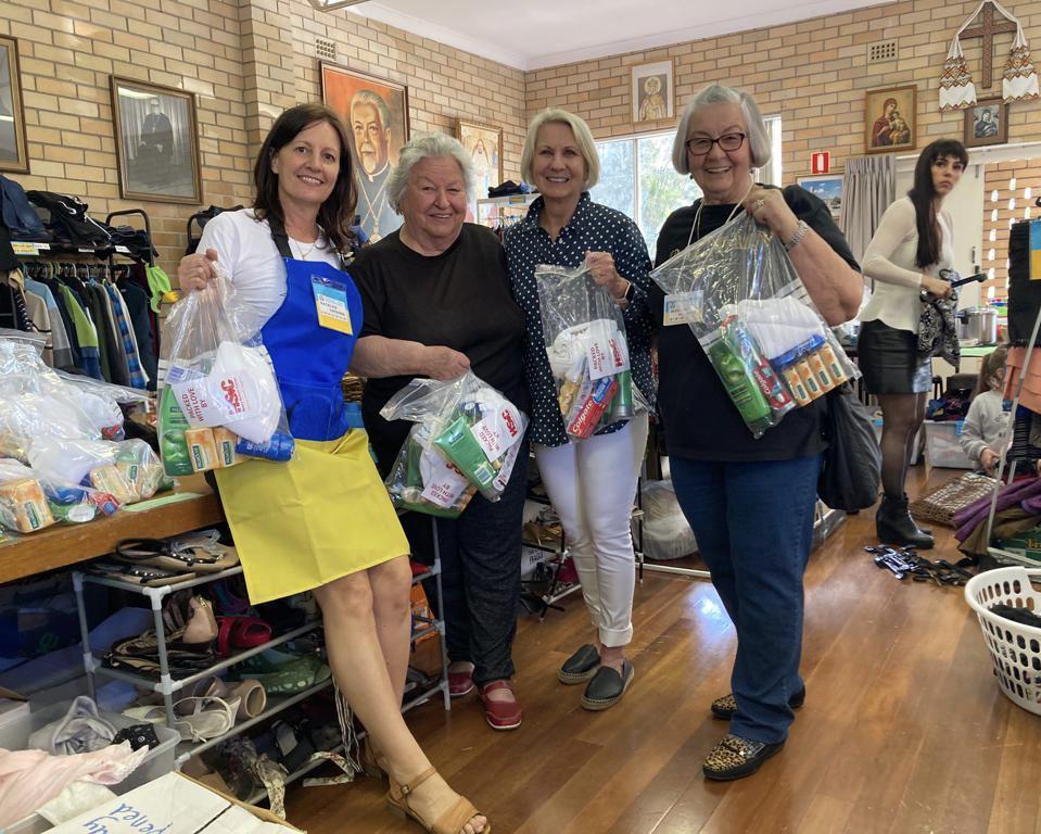
Henry Schein was able to donated 4 pallets of hygiene packs to Blue and Yellow Hearts which is a Sydney based organisation which assist displaced Ukrainians in their first few week of arriving in Australia.
Vol. 17 No. 2 ISSN 2071-7962
PUBLISHING EDITOR
Ursula Jenkins
EDITOR
Dr Andre W van Zyl
ASSOCIATE EDITORS Prof Cecilia Goracci Prof Simone Grandini
EDITOR-IN-CHIEF EMERITUS Prof Dr Marco Ferrari
EDITORIAL REVIEW BOARD
Prof Paul V Abbott Dr Marius Bredell Prof Kurt-W Bütow Prof Ji-hua Chen Prof Ricardo Marins de Carvalho Prof Carel L Davidson Prof Massimo De Sanctis Dr Carlo Ercoli Prof Roberto Giorgetti Dr Johan Hartshorne Dr Patrick J Henry Prof Dr Reinhard Hickel Dr Sascha A Jovanovic Dr Gerard Kugel Prof Ian Meyers
Prof Maria Fidela de Lima Navarro Prof Hien Ngo Dr Hani Ounsi Prof Antonella Polimeni Prof Eric Reynolds Prof Andre P Saadoun Prof Errol Stein Prof Lawrence Stephen Prof Zrinka Tarle Prof Franklin R Tay Prof Manuel Toledano Dr Bernard Touati Prof Peet van der Vyver Prof Laurence Walsh Prof Fernando Zarone
International Dentistry - Australasian Edition is published by Modern Dentistry Media CC, 15 Martinique, Calderwood Rd, Johannesburg 2062, South Africa
Tel: +27 11 702-3195 • Fax: +27 (0)86-568-1116
E-mail: dentsa@iafrica.com www.moderndentistrymedia.com

© COPYRIGHT. All rights reserved. No editorial matter published in International Dentistry - Australasian Edition may be reproduced in any form or language without the written permission of the publishers. While every effort is made to ensure accurate reproduction, the authors, publishers and their employees or agents shall not be held responsible or in any way liable for errors, omissions or inaccuracies in the publication whether arising from negligence or otherwise or for any consequence arising therefrom.
Published in association with
2 INTERNATIONAL DENTISTRY – AUSTRALASIAN EDITION VOL. 17, NO. 2
CAD-CAM single tooth lithium-disilicate restoration through combined endodontic, surgical and prosthetic therapies
Matteo Basso,1 Maria Giulia Pulcini,2 Carlo Vitelli,3 Arturo Dian,4 Katherine Radaelli5 and Clotilde Austoni6
1 Matteo Basso, DDS, PhD, MSc Head of Centre of Minimally Invasive, Aesthetic and Digital Oral Rehabilitation (CROMED), IRCCS Galeazzi Orthopaedic Institute, Dental Clinic, University of Milan, Italy.
2 Maria Giulia Pulcini, DDS Centre of Minimally Invasive, Aesthetic and Digital Oral Rehabilitation (CROMED), IRCCS Galeazzi Orthopaedic Institute, Dental Clinic, University of Milan, Italy.
3 Carlo Vitelli, Dental student Centre of Minimally Invasive, Aesthetic and Digital Oral Rehabilitation (CROMED), IRCCS Galeazzi Orthopaedic Institute, Dental Clinic, University of Milan, Italy.
4 Arturo Dian, DDS Centre of Minimally Invasive, Aesthetic and Digital Oral Rehabilitation (CROMED), IRCCS Galeazzi Orthopaedic Institute, Dental Clinic, University of Milan, Italy.
5 Katherine Radaelli, DDS, MSc student. Centre of Minimally Invasive, Aesthetic and Digital Oral Rehabilitation (CROMED), IRCCS Galeazzi Orthopaedic Institute, Dental Clinic, University of Milan, Italy.
6 Clotilde Austoni, DDS, MSc Head of Centre of Dental Traumatology and Rehabilitation (COIR), IRCCS Galeazzi Orthopaedic Institute, Dental Clinic, University of Milan, Italy.
The restorative treatment of a severely decayed, unvital tooth requires often an interdisciplinary approach, and the aesthetic and the entity of the masticatory loads are often influencing the choice of procedures and materials. A case of a 45-year-old woman, with an incompletely treated, painful upper premolar is here presented, where the aesthetic needs and functional requirements led the clinician to choose a surgical and prosthetic rehabilitative path, selecting a lithium-disilicate, monolithic block as ideal material for the final restoration.
Introduction
In case of a serious tooth decay, the treatment often requires an inter-disciplinary approach. The dentist can be required to restore aesthetic and function of an upper tooth, where the aesthetic and the entity of the masticatory loads are often influencing the choice of procedures and materials and even the general prognosis of the tooth. In particular, the factors that had to be considered in this case were the position and size of the cavity, the requirement to complete an endodontic treatment and the size of the final restoration. Moreover, having planned a prosthetic crown, the authors also considered the requirement of endodontic post, the position of the bone crest in respect to the cavity margins, the length of the root, the status of the adjacent teeth, the overall oral hygiene and the patient’s compliance and, as important consideration, the cost/benefit ratio to explain to patient. In many cases where the rehabilitation plan of a premolar includes different and complex procedures such as endodontic treatments, posts or extensive restorations, the dentist tends to choose an implant-supported prosthetic rehabilitation, because the costs of the alternative conservative treatments could be similar to those of the implant-supported ones, but the overall prognosis of a tooth-supported prosthesis may result, in the mind of professionals and in a certain part of literature,1 lower than that of a crown over implant. In fact, the prognosis of different rehabilitations is strongly affected by many factors, mainly the dentist and his skills, but also the used materials. However, considering the overall length in terms of months, the rehabilitative treatment
CLINICAL 4 INTERNATIONAL DENTISTRY – AUSTRALASIAN EDITION VOL.17, NO. 2
of a natural tooth is usually faster and the conservative treatment represents always the best choice biologically, if allowed. In this case the right selection of the prosthetic material could be decisive.
Clinical case presentation
A 45-year-old female patient, B.S., referring intensive pain in her upper left dental arch, asked for a visit at the dental clinic of the IRCCS Istituto Ortopedico Galeazzi (Milan, Italy). During the anamnesis she told to be in good health status, without being affected by any chronic disease, and no smoking.
During the clinical oral examination, she didn’t exhibit any mucosal lesions, she presented an optimal level of oral hygiene but there were a lot of incongruous restorations and an apparently provisional restoration on tooth #25.
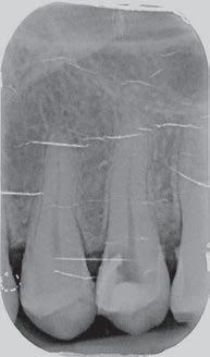
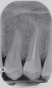
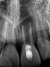
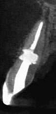
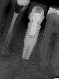
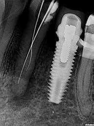
This element was not stimulated with the cold test and the radiographic image revealed an incomplete endodontic treatment (Figs. 1-2). The element seemed to present a suitable root length for a conservative restoration, but the apical position of the carious lesion and the proximity of the interdental bone ridge didn’t allow a correct rehabilitation with prosthetic crown, respecting the biological width.2
Considering the patient’s factors (e.g. age, level of oral hygiene, absence of smoking or other risk factors) and status of the tooth (e.g. length of the root, endodontic access, periodontal status), it was communicated to the patient that the treatment plan would include an endodontic-prosthetic restoration through conservative therapies and CAD-CAM
Figure 2: Initial radiograph showing endodontic dressing that had been present for some months, but the treatment was never completed. Note the depth of the caries lesion and the proximity of the interdental bone ridge, which may represent an obstacle for prosthetic rehabilitation.
restoration in lithium-disilicate.3-6
Operational phases
The patient at the first appointment immediately required a quick solution for the pain, consecutive to an incomplete endodontic treatment and a partially removed carious lesion. So, the first step consisted in the removal of the decayed tissue of the distal face of the tooth 25 in its coronal portion and in the first third of the root.
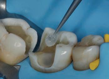
The cervical limit of the decay was exposed; then the wall was restored with a glass hybrid material (EQUIA Forte™, GC) coated with the light-curable EQUIA Forte Coat™ to obtain a more resistant material even in case of occlusal loads. 7-9 A glass hybrid material was chosen because the apical edge of the tooth cavity was under the gingival margin, so it was impossible to obtain a correct isolation for a composite restoration: it’s known that the glass hybrid materials can tolerate acid and humid environments more than composite. 7-9
The glass hybrid EQUIA Forte was preferred to glass ionomer because better long-term results are reported in literature. 7-10
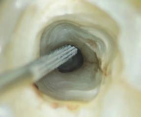
After that, the tooth was endodontically treated. The tooth had only one root canal, processed with a hand file READY STEEL K-File™ (Dentsply Sirona) and for the shaping and refinement with mechanical file PROTAPER GOLD™ (Dentsply Sirona) at a working length of 20 mm.
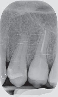
The canal was sealed with a Thermafil™ cone (Dentsply Sirona) with an apical diameter of 0.30 mm (Figs. 3-4).

CLINICAL INTERNATIONAL DENTISTRY – AUSTRALASIAN EDITION VOL.17, NO. 2 5
Figure 1: Initial situation. The patient reported generic pain in the second quadrant, where there was a restoration in temporary material on tooth number 25.
The third step of the treatment consisted of the crown lengthening, necessary to expose an adequate part of the root to obtain, after healing, the correct adhesion of the composite for the pre-prosthetic restoration and the successive prosthetic rehabilitation.


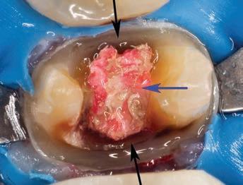
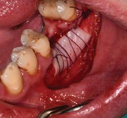
After the surgical flap elevation of the tissue and the bone remodeling, the flap was repositioned apically and sutured with a vertical mattress suture anchored in the periosteum (Figs. 5-6). The suture was removed after 7 days (Fig. 7).
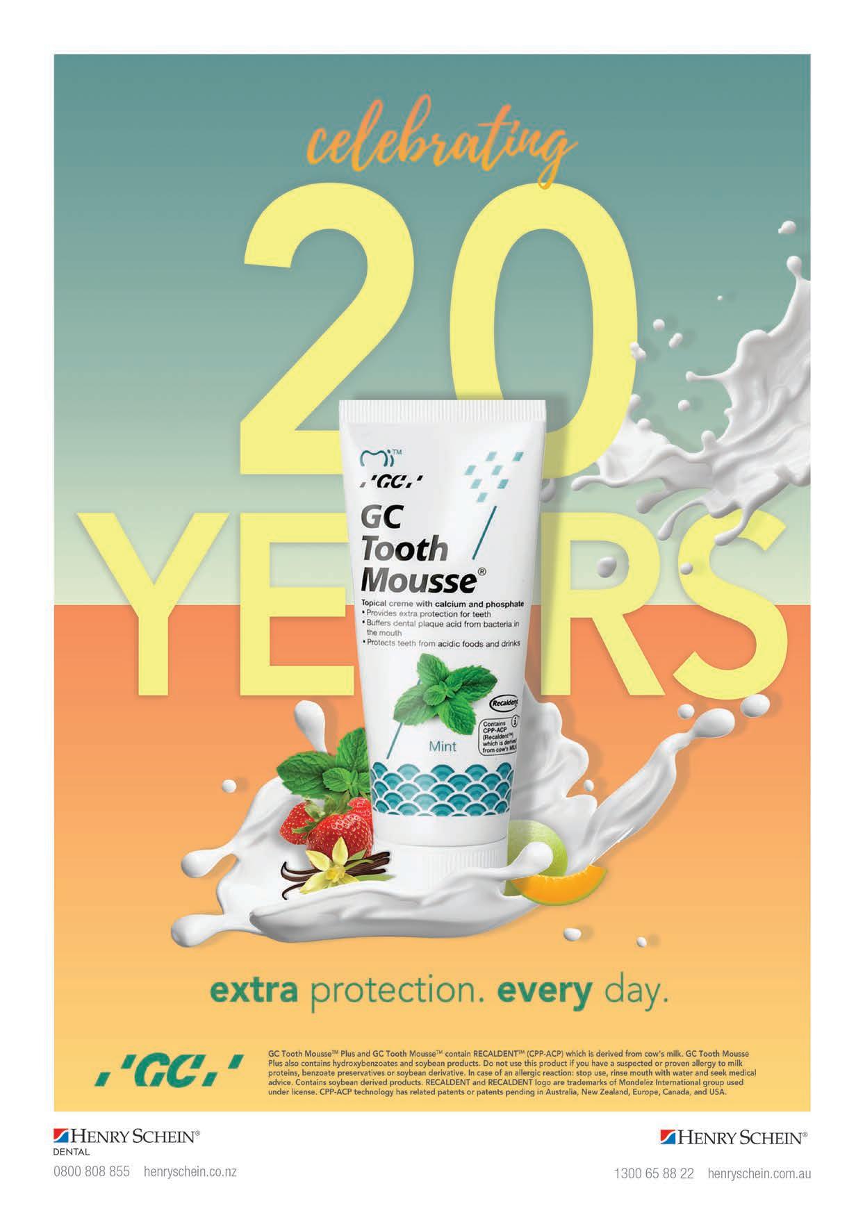
During the fourth phase, after waiting a postsurgical healing time of 4 weeks necessary for the correct maturation of the tissues (Fig. 8), the glass hybrid and coronal part of the endodontic material was removed with the Gates Glidden™ cutters (Dentsply Sirona) with 01-02-03 size. A
BASSO ET AL
6 INTERNATIONAL DENTISTRY – AUSTRALASIAN EDITION VOL.17, NO. 2
glass fibre
Figure 3: Root canal therapy completed under proper isolation. Figure 4: Radiography of completed root canal therapy and reconstruction made completely in glass hybrid cement.
Figure 5: Clinical crown lengthening with a minimally invasive technique without mesial and distal discharges. Note the proximity of the reconstruction in glass hybrid material to the mesial bone ridge.
Figure 6: Suture at the end of surgical therapy. It was left in place for 7 days
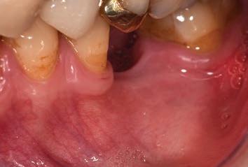
Figure 7: Suture removal at 7 days. Post-surgical edema is still present.
Figure 8: Recovery 2 weeks after surgery. Note the disappearance of post-surgical edema. The provisional crown was placed after two weeks to allow the formation of an epithelial-connective seal in the area.
Figure 9: Prosthetic preparation of the dental element with BOPT technique. Note the minimal aggressiveness in the dental groove, recently traumatized by surgery.
Figure 10: First relining in acrylic resin of the provisional crown in PMMA obtained by digital scanning of the arches, suitable to condition the tissues after only 4 weeks from the operation, taking advantage of the reparative thrust that follows a periodontal surgery.
Figure 11: Provisional crown in PMMA finished and positioned. Composite reconstructions on teeth 24 and 26 have been replaced in order to construct correct contact points with the final crown

Figure 12: Final radiography after positioning of the endodontic post, composite reconstruction and insertion of the provisional crown in PMMA. Note the distance between the edge of the cement used to fix the crown, more radiopaque than PMMA, and the new bone ridge created with periodontal surgery.

post with a medium size truncated cone form, Anatomical Post (DENTALICA, Italy), was inserted and bonded with a self-adhesive dual-cure cement (G-CEM LinkAce™ translucent, GC). The permanent composite restoration was completed with G-ænial Posterior™ shade A3 composite (GC) bonded with its respective self-etch adhesive (G-ænial Bond™).
After the restoration, the tooth was prepared with the BOPT technique5-6 . A provisional PMMA crown, obtained with an optical scan done before the preparation of the element with a AADVA IOS100 scanner (GC), was placed. During this phase the obsolete restorations of the teeth 24 and 26 were replaced. (Figs. 9-12)
After 4 more weeks, the prosthetic abutment was refined and the definitive dental impression was taken with poly


vinylsiloxane-ether (PVS-E, Exa’Lence™, GC) (Figs. 13-14). The dental impression was sent to the laboratory, where it was optically scanned and a CAD-CAM path was set.
As a consequence of the newly surgically modified prosthetic margin, the appropriate length of the abutment for an adhesive cementation had been obtained, and the high aesthetic requirement and the contemporary need of containing costs with a monolithic crown, led the clinical choice to a lithium-disilicate crown with high translucency and suitable for the CAD-CAM technology.
The chosen material was the Initial LiSi Block™ (GC), because the ultra-thin structure of the Initial LiSi Block’s has two important advantages: first of all, the block is easy to be milled with the use of chairside milling machine in the lab, and secondly this material doesn’t require other steps in the

BASSO ET AL INTERNATIONAL DENTISTRY – AUSTRALASIAN EDITION VOL.17, NO. 2 7
Figure 13: Final preparation of the tooth with the aim of taking the definitive impression. Note the total absence of bleeding despite having extended the preparation margins more apically than the first provisional.


Figure 14: Definitive impression in PVS-E. The impression was scanned by a laboratory scanner and an entire CAD-CAM path was created for milling the final crown.
Figure 18: Etching of the prosthetic abutment with orthophosphoric acid for 40”
oven to be sintered or glazed. In fact, Initial LiSi Block is the first completely crystalized lithium-disilicate block, so the time for its crystallization could be saved and the software for the finishing and glazing would not have to compensate for any material contraction due to the temperature in the
Figure 19: Treatment of the internal surface of the restoration with 9% hydrofluoric acid for 20”. Being lithium disilicate, the restoration must be placed in hot water for at least 60” after etching to eliminate some lithium salts that could form on the inner surface and which could weaken the adhesive bonds.
crystallizing oven.
In this way, margins remain extremely thin and clear and it’s particularly useful in this case. It’s also possible to reduce costs compared to the use of a highly aesthetic and functional material.
BASSO ET AL
8 INTERNATIONAL DENTISTRY – AUSTRALASIAN EDITION VOL.17, NO. 2
Figure 15, 16 &17: Views of the monolithic restoration in lithium disilicate, polished and finished.
 BASSO ET AL
Figure 20: Application of the silane coupling agent to be left in place for at least 60”
Figure 21: Adhesive cementation with adhesive composite resin. The absence of bleeding, the respect of the manufacturer’s instructions and the control of the prosthetic margins during the procedures is fundamental for the maintenance and the good outcome of the cementation.

Additionally, the ultra-thin structure of the Initial LiSi Block permits easily polishing of the restoration even after the occlusal adjustments, leaving the area extremely uniform and smooth. This reduces the finishing times, the brightness lasts longer and the occlusal contacts produce less abrasion of the restoration and of the antagonists (Figs. 15-17).

Regarding the luting phase, the tooth abutment was etched with 37% orthophosphoric acid for 15 seconds (Fig. 18), rinsed and then dried with compressed air. The definitive crown was etched with 9% hydrofluoric acid for 20 seconds (Fig. 19), rinsed and dried with compressed air. According to manufacturer’s instruction, it is not recommended to etch Initial LiSi Block for more than 20 seconds, in order to preserve all properties of the material. Since the acid etching with the hydrofluoric acid may result the formation of crystals of lithium salts on the inner surface of the crown,10 it’s important to put the crown in hot water for 1 minute after the acid removal, to eliminate the crystals and prevent any interference with the adhesive cementation, and then it must be carefully dried. Before the placement of the adhesive cement, a specific coupling agent was placed on the internal surface of the crown, in order to obtain a stronger adherence between the ceramic and the luting resin. For this reason, G-Multi Primer (GC) was selected and applied (Fig. 20). The luting phase was finally performed with the G-CEM LinkForce™ (GC), after the placement of the dedicated adhesive system (G-Premio Bond) on the tooth, blowing them with compressed air for 20 seconds, without curing them before the luting phase in order to allow a correct fit of the crown. Each crown surface was cured for 40 seconds (120” in total
Figure 22: Final palatal view. Note the excellent integration of the margins also on the palatal side.
in order to correctly cure both adhesive and resin cement even through the ceramic) and the excesses of the luting material were finally removed.

Discussion
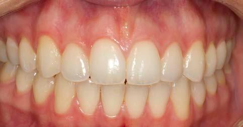
At the end of the procedures, the restoration was precisely seated at equigingival level of the margins, it appeared to be morphologically integrated in the dental arch, with correct contact points and with a good chromatic match with the adjacent elements (Figs. 21-24). Upon X-ray examination, it was possible to see that the subgingival margins were also integrated, without any step or any plaque-retaining area that could be a problem for the home dental hygiene (Fig. 25). The patient didn’t refer pain anymore and was completely satisfied with the prosthetic rehabilitation, that she found perfectly integrated at both functional and chromatic levels. She also found the colour of the prosthesis was better than her natural teeth.
CAD-CAM technology and chairside procedures, including the milling process that takes place completely inside the dental clinic, are actually a solid reality and these kind of digital machines are easily available for many years8
The required time for the a complete crown production inside the dental clinic, from projecting, milling to finishing, may vary depending on the material: the required production time ranges normally from 1 hour (for the simplest materials) to more than 4 hours (for the materials that after milling require more tests and passages in finishing furnaces. For this reason, and due to the diffusion of CAD-CAM procedures in laboratories as well, chairside procedures are actually less
10 INTERNATIONAL DENTISTRY – AUSTRALASIAN EDITION VOL.17, NO. 2
Figure 23: Final occlusal view.
Figure 24: Final occlusal view at higher magnification.
which mean expenses for the clinic and less time to dedicate to dental activities.
Conclusions
An ideal monolithic material must have some fundamental characteristics, in order to make it an adequate choice for aesthetic and functional rehabilitations:
• High mechanical strength.
• Adequate translucency.
• Ease of processing and milling.
• Availability of different shades.
Figure 25: Final radiography of the restoration in its position. It can be seen that margins were excellently integrated and the biological width was respected.
appreciated by many dentists, who see them as a possible waste of time, diverting dentists from the real clinical activity
However, the reliability of modern CAD-CAM systems and new materials allow dentists and laboratories to make new choices, even in the name of a smoother workflow and cost control, when possible. A millable material that has considerable aesthetic properties is in any case indispensable, whether a clinician decides for a full chairside procedure, or for sending the impression to the laboratory. Also the “monolithic” materials cannot actually afford to be opaque, not very natural and not very translucent, because very few professionals and patients are inclined to accept aesthetic compromises in modern times.
Moreover, from the dentist’s point of view, polishing procedures after possible occlusal adjustments should not require much time, neither dedicated instruments and burs,


• Possibility of effective and durable luting with the most common adhesive systems or cements.
• Easy polishing phase involving few steps and burs.
• Availability for the most common chairside and laboratory milling machines (compatibility).
There is not an ideal, universal material that could be chosen for all prosthetic procedures. By the way, while selecting the material that could appear clinically ideal for a specific case, only a good mix of these characteristics can determine a clinical success of a prosthetic rehabilitation procedure with monolithic materials and, ultimately, full patient satisfaction.
References
1. F.C. Setzer and S. Kim; Comparison of Long-term Survival of Implants and Endodontically Treated Teeth J Dent Res. 2014 Jan; 93(1): 19–26. doi: 10.1177/0022034513504782 Ruskin JD, Morton D, Karayazgan B, Amir J. (2005). Failed root canals: the case for extraction and immediate implant placement. J Oral Maxillofac Surg 63:829-831 Lundgren D, Rylander H, Laurell L. (2008). To save or extract, that is the question. Natural teeth or dental implants in periodontitis-susceptible patients: clinical decision-making and treatment strategies exemplified with patient case presentations. Periodontol 2000. 47:27-50
BASSO ET AL
INTERNATIONAL DENTISTRY – AUSTRALASIAN EDITION VOL.17, NO. 2 11
BASSO ET AL
2. Lanning SK, Waldrop TC, Gunsolley JC, Maynard JG. Surgical crown lengthening: evaluation of the biological width. J Periodontol. 2003 Apr;74(4):468-74.
3. Khaled Al-Omiri M., Mahmoud A. A., Rayyan M.R., Abu-Hammad O. Fracture resistance of teeth restored with post-retained restorations: An overview. Journal of Endodontics. 2010;36(9):1439–1449. doi: 10.1016/j.joen.2010.06.005.
4. Barcellos R. R., Correia D. P. D., Farina A. P., Mesquita M. F., Ferraz C. C. R., Cecchin D. Fracture resistance of endodontically treated teeth restored with intra-radicular post: the effects of post system and dentine thickness. Journal of Biomechanics. 2013;46(15):2572–2577. doi: 10.1016/j.jbiomech.2013.08.016.
5. Loi I, Di Felice A. Biologically oriented preparation technique (BOPT): a new approach for prosthetic restoration of periodontically healthy teeth. Eur J Esthet Dent. 2013 Spring;8(1):10-23.
6. Serra-Pastor B, Loi I, Fons-Font A, Solá-Ruíz MF, AgustínPanadero R Periodontal and prosthetic outcomes on teeth prepared with biologically oriented preparation technique: a 4-year follow-up prospective clinical study. J Prosthodont Res. 2019 Apr 8. pii: S1883-1958(18)30193-2. doi: 10.1016/j.
jpor.2019.03.006.
7. Türkün LS, Kanik Ö.; A Prospective Six-Year Clinical Study Evaluating Reinforced Glass Ionomer Cements with Resin Coating on Posterior Teeth: Quo Vadis? Oper Dent. 2016 Nov/Dec;41(6):587-598. Epub 2016 Aug 29.
8. Basso M, Nowakowska J.K, Del Fabbro M. Long-term Dental Restorations using high-viscosity Coated Glass ionomer Cements. Abstract 2494-IADR 2011, San Diego, USA
9. Lohbauer U1, Krämer N, Siedschlag G, Schubert EW, Lauerer B, Müller FA, Petschelt A, Ebert J.Strength and wear resistance of a dental glass-ionomer cement with a novel nanofilled resin coating.Am J Dent. 2011 Apr;24(2):124-8
10. Hesse D, Bonifácio CC, Bönecker M, Guglielmi Cde A, da Franca C, van Amerongen WE, Colares V, Raggio DP. Survival Rate of Atraumatic Restorative Treatment (ART) Restorations Using a Glass Ionomer Bilayer Technique with a Nanofilled Coating: A Bi-center Randomized Clinical Trial. Pediatr Dent. 2016 Jan-Feb;38(1):18-24.
Reprinted with permission by GC get connected
12 INTERNATIONAL DENTISTRY – AUSTRALASIAN EDITION VOL.17, NO. 2
On corporate identity and the pursuit of ‘work’: a reflection of GC’s 100 years
Tales of grassroots, ground-up success are still the narratives we love to celebrate. Resilience after loss. Triumph through adversity. Such is the blueprint for an idealist seeking change. For GC founders Kiyoshi Nakao, Yoshinosuke Enjo and Tokuemon Mizuno, the challenges of the market in a post-war world only fuelled their vision: to bring value to society through quality and innovative dental products, serving the vitality of people across the globe.
Formed in Japan in 1921, GC’s entry into the dental manufacturing field a year later with ‘Standard Cement’ came short of the breakthrough they had anticipated. Coming to terms with the reality of running an enterprise, the founders learned to embrace an external voice, one most important: the customer. So began a lifelong devotion to serving the needs of the end user, fulfilled by continual improvement and true, quality products.
focuses on the spirit of all associates— Nakama— and their united, localised efforts to serve the development of dental science and public oral health care worldwide. With the strength of Nakama, GC maintains its status of a privately held company independent from investors and external capital, ensuring the prioritisation of innovation and sustainable growth for many years to come
Today, the term ‘social responsibility’ is a stakeholder expectation when implementing corporate governance — yet for GC, the answer to such newer concepts like corporate social responsibility was founded one century prior. Its 100-year philosophy of SEMUI, a combination of ‘selflessness, objectivity, charity and wisdom’ is the persisting legacy of its founders today. These unchanging values continue to enable outstanding contributions to the dental industry whilst improving global welfare through oral healthcare — all the while championed by GC’s unique sentiment on ‘work’, one seldom endorsed around the world:
“Translated to English, the Japanese verb hataraku means work, which has two meanings: ‘labour of efforts’ and ‘a composition or product of art’.”
Operating in over 100 countries today, GC’s industry-leading products and services is an exceptional testament to its own success, powered by 100 years of history, a robust organisational identity and an uncompromising philosophy:
“True products are made for the good of others, not for the sake of oneself.”
–Kiyoshi Nakao
For associates of GC, the meaning holds a higher purpose. Stripped of its complicated undertones of ‘labour’, ‘work’ should mean to realise a vision; to conceptualise, create and complete. The success of GC on a global scale for 100 years and counting is thus owed to its internal operational model; one that departs from the traditional ‘employer vs. employee’ framework. Instead, GC culture focuses on the spirit of all associates — Nakama — and their united, localised efforts to serve the development of dental science and public oral health care worldwide.
With the strength of Nakama, GC maintains its status of a privately held company independent from investors and external capital, ensuring the prioritisation of innovation and sustainable growth for many years to come. Operating in over 100 countries today, GC’s industry-leading products and services is an exceptional testament to its own success, powered by 100 years of history, a robust organisational identity and an uncompromising philosophy: “True products are made for the good of others, not for the sake of oneself.”
 – Kiyoshi Nakao
C E L E B R A T E 1 0 0 Y E A R S W I T H G C
Masterclass in Clinical Practice
Implant Dentistry with
Dr Andre W van Zyl1 Dr Inus Snyman2
Introduction
The long-term survival and success of dental implants depend on multiple factors. One of these factors is the soft tissue surrounding dental implants. To understand the anatomy of soft tissue around dental implants, it is worth revisiting the normal anatomy of soft tissue surrounding teeth.
The importance of keratinized tissue around dental implants
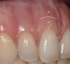
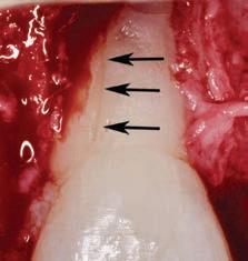
The main role of the periodontium is to anchor a tooth to the jaw bone. The periodontium consists of the gingiva, periodontal ligament, root cementum and alveolar bone proper.1 The periodontium also plays a major role in defence which contributes to its health in the natural dentition as well as around dental implants.1, 2 Three types of oral mucosa can be distinguished, namely the masticatory mucosa (gingiva and hard palate), specialized mucosa (dorsum of the tongue) and lining/alveolar mucosa. The gingiva covers the coronal alveolar process and cervical portion of teeth and consists of an epithelial layer and underlying connective tissue. The gingiva is always keratinized and consists of the attached gingiva and the free gingiva which terminates at the free gingival margin. Apically, the attached gingiva extends to the mucogingival junction, where it becomes continuous with the alveolar mucosa (Fig.1). The immobile attached gingiva is firmly attached to the underlying alveolar bone and cementum by connective tissue fibers (Sharpey’s fibers). The alveolar mucosa on the other hand, is loosely bound to the underlying lamina propria and is therefore mobile.1
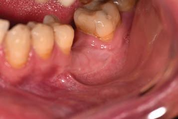
The width of the band of attached gingiva around teeth varies from site to site and the range of variation is between 1-9 mm. In the maxilla, the vestibular gingiva is usually widest at the incisors and narrowest at the premolars. In the mandible, the lingual gingiva is especially narrow at the incisors and wide at the molar sites (Fig. 2).1 This explains why certain potential dental implant sites will naturally present with less attached gingiva after tooth extraction.
Scan to see video

1 Andre W. van Zyl

MChD (Oral Medicine & Periodontics)
Private Practice, Hermanus, South Africa
2 Inus Snyman
BChD, PDD (Implantology), PGDipDent (Oral Surgery), PGDipDent (Implantology), MChD, FCD(SA) OMP
Private Practice, Stellenbosch, South Africa
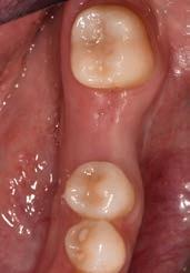
Although low trauma extraction techniques have been discussed in a previous Masterclass, it is relevant to emphasize the importance of not approximating the soft tissue margins over a tooth socket by suturing. Leaving the extraction socket open for healing to occur will create more attached gingiva at the future implant site (Fig. 3). This newly formed gingiva can then be moved buccally by placing the crestal incision more towards lingual during implant placement or exposure.
Keratinized tissue around implants
Compared to natural teeth, the soft tissue around dental implants provides less of an anatomical barrier as it does not have inserting fibers attaching to the implant or abutment.2-4 An implant has a transmucosal component (an abutment, neck of the implant, or implant restoration) that protrudes through the overlying mucosa/
14 INTERNATIONAL DENTISTRY – AUSTRALASIAN EDITION VOL.17, NO. 2
Figure 1: Healthy soft tissue in the natural dentition. FG= free gingiva, AG=attached gingiva, AM=alveolar mucosa
MASTERCLASS
IN IMPLANT DENTISTRY
Figure 2: Variation in the width of attached gingiva at different sites, with a clearly visible mucogingival junction.
Figure 3: Healed extraction site 3-months after low trauma extraction, with adequate amount of attached keratinized tissue for implant placement.
gingiva, which heals and adapts around it without an inserting connective tissue attachment such as around teeth. Although some studies showed circular fibers present around the transmucosal part of implants4, it is well-known that the barrier function of the peri-implant tissue is less effective than that of natural teeth. The importance of having sufficient keratinized tissue around dental implants has been emphasized in recent studies.2-5 Mobile alveolar mucosa is not able to provide an adequate seal between the oral environment and the implant body. In patients with inadequate plaque control, this may become even more crucial, as inflammation may distend the mucosa more readily and render the area more uncomfortable to oral hygiene efforts. This in turn may lead to more bone loss around the neck of the implant.2, 4, 6, 7
A reduced width of keratinized tissue around dental implants is associated with increased biofilm accumulation, soft-tissue inflammation, greater patient discomfort, mucosal recession, marginal bone loss and an increased prevalence of peri-implantitis.4, 7 Free gingival autogenous grafts are considered the standard of care for surgical intervention to effectively increase the width of keratinized tissue around dental implants. The presence of a minimum width of at least
2-3mm of keratinized tissue around dental implants should therefore be assessed routinely in patients with implant supported restorations. 7 It should, however, be stressed that the keratinized tissue should have an attached component to protect the coronal bone around the implant to provide an effective seal. In recent studies the importance of adequate thickness of the keratinized tissue has also been emphasized.3
Epithelial palatal transplant (EPT) to increase the width and thickness of keratinized tissue around implants
Grafting of soft tissue can be done at three different time periods: before implant placement (Figs 4a-c), at the same time (Figs 5a-c) or after implant placement (Figs 6a-c). Experienced clinicians may opt to perform an EPT simultaneously with implant placement as this saves multiple surgical procedures and is more cost effective. This is shown in Fig 5 and also in the video link provided. This is a complex procedure which should not be attempted by inexperienced clinicians. Grafting before the implant placement is the more predictable procedure and provides a better implant environment to place the implant.
INTERNATIONAL DENTISTRY – AUSTRALASIAN EDITION VOL.17, NO. 2 15
Figure 4a: Pre-operative view showing alveolar mucosa almost to crest of ridge
Figure 4b: Graft secured with vestibular deepening done as well
Figure 4c: Post-operative view showing graft healing after 8 weeks
Conclusion:
Grafting of keratinized tissue is often neglected, with detrimental long-term results for the implant. The most common reason for neglecting this very important part of implant dentistry is because of the morbidity of a second surgical procedure. Performing the two procedures together solves the dilemma of having to do two procedures and is also more cost effective.
Patients need to be informed of the necessity, rather than ending up with peri-implantitis and regular interventions for the treatment thereof. An added benefit of doing the EPT, is the vestibuloplasty it gives that enables better plaque control.
References
1. Berglundh T GW, Sanz M, Lang NP, editors. Lindhe’s Clinical Periodontology and Implant Dentistry. John Wiley & Sons. 2021, Jul 28.
2. Kelekis-Cholakis A. The Importance of Keratinized Tissue Around Implants. Journal of Cosmetic dentistry. 2015;31:102.
3. Linkevicius T, Puisys A, Steigmann M, Vindašiūtė E, Linkevičienė L. Influence of Vertical Soft Tissue Thickness on Crestal Bone Changes Around Implants with Platform Switching: A Comparative Clinical Study. Clinical implant dentistry and related research. 2015;17 6:1228-36.
4. Rodriguez X, Navajas A, Vela X, Fortuño A, Jimenez J, Nevins M. Arrangement of Peri-implant Connective Tissue Fibers Around PlatformSwitching Implants with Conical Abutments and Its Relationship to the Underlying Bone: A Human Histologic Study. The International journal of periodontics & restorative dentistry. 2016;36:533-40.

5. Wang Q, Tang Z, Han J, Meng H. The width of keratinized mucosa around dental implants and its influencing factors. Clin Implant Dent Relat Res. 2020;22(3):359-65.
6. Linkevicius T, Puisys A, Linkeviciene L, Peciuliene V, Schlee M. Crestal Bone Stability around Implants with Horizontally Matching Connection after Soft Tissue Thickening: A Prospective Clinical Trial. Clin Implant Dent Relat Res. 2015;17(3):497-508.
7. Sanz M, Schwarz F, Herrera D, McClain P, Figuero E, Molina A, et al. Importance of keratinized mucosa around dental implants: Consensus report of group 1 of the DGI/SEPA/Osteology Workshop. Clin Oral Implants Res. 2022;33 Suppl 23:47-55.
MASTERCLASS
IMPLANT
16 INTERNATIONAL DENTISTRY – AUSTRALASIAN EDITION VOL.17, NO. 2
IN
DENTISTRY
Figure 5a: Preoperative view with mucogingival line shown in blue
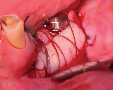
Figure 5b: Simultaneous implant placement and epithelial palatal transplant
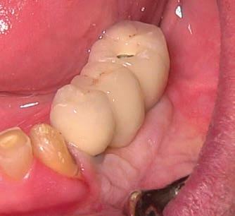
Figure 5c: Postoperative view with crowns placed. Rugae can be seen but, as it is not an aesthetic area, this is of no consequence
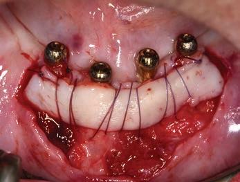
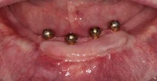
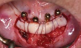
Figure 6a: Implants placed years before with peri-implantitis and no keratinized attached tissue buccal of implants.
Figure 6b: Graft providing keratinized tissue as well as vestibuloplasty. Patient can wear prosthesis but it has to be eased to ensure no pressure on graft
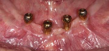
Figure 6c: Postoperative view showing a stable attached peri-implant keratinized tissue and vestibular deepening giving better access for plaque control
Case background
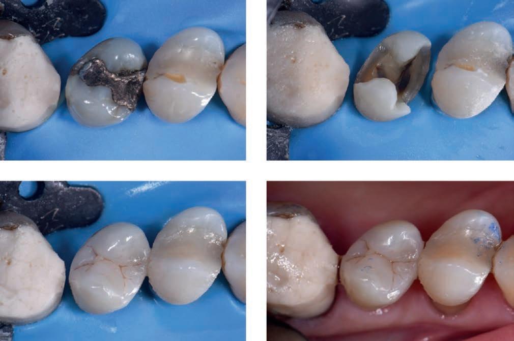
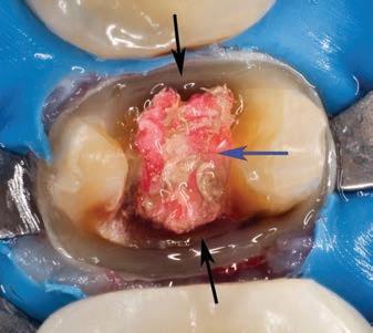
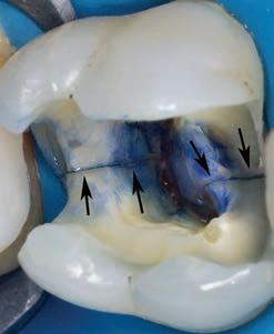
A stable ASA 2 65-year old female presented to the practice for restorative dentistry with a medical history significant for a non-descript immunoglobulin deficiency, for which she receives regular infusions. She reports no known drug allergies. Clinically, she was diagnosed with an occlusal peripheral rim fracture leaving a food trap on tooth 1.4 (FDI notation). Tooth 15 featured an extensive amalgam with extreme proximity to the distal marginal ridge, which exhibited distal vertical axial fractures as a result of cyclic expansion-contraction over time.
The restorative goal of minimally invasive direct dentistry would be complicated by the undoubtedly dark dentin substrate under the amalgam. A material was sought that featured both an excellent chameleon mechanism as well as physical properties to maximize the prognosis of direct restorations in this area.
Restorative procedure
The patient was subjected to topical anesthetic prior to buccal infiltration using 1 carpule of 2% Lignocaine with 1:100,000 epinephrine. A rubber dam was affixed prior to preparation of tooth 15MO with dissection of the distal vertical marginal ridge fracture. The margins of tooth 14O and 15MOD were refined before bevelling as the ends of enamel rods facilitate better bonding relative to the sides of enamel rods. A 27 micron aluminum oxide micro air abrasion treatment was completed prior to affixing, wedge and matrix to reconstruct the mesial marginal ridge of tooth 15. A matrix-inmatrix solution was used to recreate the proximoaxial contour of 15D This provided hermetic closure at the proximogingival cavosurface margin as well as an ideal contour for the missing axial wall.
Following a total etch technique, a 2% Chlorhexidine scrub was completed for 30 seconds and the dentin blot dried to a moist state. A 5th generation bond was applied, air thinned and cured as per manufacturer instructions. Microlayers are important during the delicate first 5 minutes of hybrid layer formation, and were completed using 0.25mm increments of CLEARFIL MAJESTY™ Flow (Kuraray Noritake Dental Inc.). This technique can be expected to increase significantly the shear bond strength to dentin1,2 This was completed both in the proximal box floor area as well as mid-occlusally. The marginal ridge was completed using CLEARFIL MAJESTY™ ES-2 Universal (Kuraray Noritake Dental Inc.). Since the dentin base was heavily stained, CLEARFIL MAJESTY™ Flow was used before utilizing CLEARFIL MAJESTY™ ES-2 Universal in a lobe-by-lobe creation of occlusal anatomy. Post-operative occlusal checks verify that the restoration is conformative to occlusion and esthetically excellent with no visible marginal show.
Premolar case with Clearfil Majesty™ ES-2 Universal
ADVERTORIAL 18 INTERNATIONAL DENTISTRY – AUSTRALASIAN EDITION VOL.17, NO. 2
Clarence P. Tam1
1 Dr Clarence P. Tam, HBSc, DDS, AAACD, FIADFE Private Practice limited to Cosmetic and Restorative Dentistry, Auckland, New Zealand
www.clarencetam.co.nz
Rationale for material choice
The marginal ridges were micro-layered horizontally as was the floor of the resulting Class I preparation as per a reduced layer thickness-technique modification of Nikolaenko et al,3 whereas the highest shear bond strengths were found when a 1mm horizontal layering technique was used.
CLEARFIL MAJESTY™ ES-2 Universal is at the forefront of a simplified restorative armamentarium for the modern practice. It takes cloud-shading one step further by offering a “Universal” shaded composite featuring Light Diffusion Technology (LDT) with simultaneous ideal sculptability, optical metamerism and physical properties for use in any restorative situation in the mouth. Featuring barium glass nano fillers and proprietary pre-polymerized nanoparticle fillers, the latter boasts a high refractive matrix that is able to disperse light and fool the eye with even the thinnest of layers, obviating the need for opaquer composites in cases like the one featured. When paired with CLEARFIL MAJESTY™ Flow in a conservative layered technique, the 81% filled flowable produces a radiographically well-demarcated layer, and the superficial CLEARFIL MAJESTY™ ES-2 Universal boasts
an easy-to-polish robust single shade restorative solution that will virtually fulfil all of your restorative needs for nonbleaching patients.
Physically, with compressive strength is rated at 348 MPa and flexural strength at 116 MPa, CLEARFIL MAJESTY™ ES-2 Universal is in the range of natural enamel and dentin. The built-in fluorescence is very enamelomimetic, which is excellent for nightclub social situations.
References
1. Bertschinger C, Paul SJ, Luthy H, Scharer P. Dual application of dentin bonding agents: effect on bond strength. Am J Dent. 1996;9(3):115-119
2. Magne P, Kim TH, Cassione D, Donovan TE. Immediate dentin sealing improves bond strengths of indirect restorations. J Prosthet Dent. 2005;94(6):511-519
3. Nikolaenko SA, Lohbauer U, Roggendorf M, Petschelt A, Dasch W, Franenberberger R. Influence of C-Factor and layering technique on microtensile bond strength to dentin. Dental Mater. 2004;20(6):579-585
ADVERTORIAL INTERNATIONAL DENTISTRY – AUSTRALASIAN EDITION VOL.17, NO. 2 19 1 2 3
4
 Svetlana V. Chlebas
1 Svetlana V. Chlebas
Lecturer, National Medical Academy for postgraduate training, Kyiv, Ukraine. Private Practice, Scientific Centre for Clinical Stomatology SNKZ. training
Contact: khlyebassv@ukr.net
Publisher’s note: This contribution is an abridged and revised version of the original contribution published in the Ukrainian dental journal Dentaclub 3-4/2015.
Introduction
The demands on dental restorations in terms of functionality, aesthetics and durability have risen significantly in recent years, and today a wide range of modern composites are available on the market which largely meet such requirements. As a result, dentists are now spoilt for choice. The material chosen should, however, be equally suitable for the posterior and anterior regions and also have a high level of stability, meaning it can also be recommended for restorations of extensive cavities in the masticatory loadbearing region. Last but not least, the economical factor also plays an important role in selection. The material should therefore be time-saving and easy to apply.
My choice of composite is the universal nanohybrid restorative material Polofil NHT from VOCO, which combines the tried and tested composite technology with innovative nanotechnology, providing benefits both in terms of material properties and handling. Thanks to the nanoparticles evenly distributed in the matrix, Polofil NHT has a high filler content of over 83% by weight, resulting in a low polymerisation shrinkage of under 1.8% by volume.
At the same time, the material has a high compressive strength of over 440 MPa, a high flexural strength of over 157 Mpa, a modulus of elasticity of 17,000 MPa similar to that of dentine and a high abrasion resistance of under 20 µm (ACTA abrasion). This makes Polofil NHT ideally suited for restorations in the posterior region. In Polofil NHT I have a material with which even cases of bruxism can be treated appropriately and with long lasting results, which is particularly important in view of the ever increasing number of findings.
Polofil NHT is also perfectly suited for anterior restorations as its high translucency and chameleon effect enable highly aesthetic results with just one shade which correspond to the natural tooth. Polofil NHT also boasts outstanding handling. The material does not adhere to the instrument during layering and modelling, preventing it from developing a “ripped look”. The increments can be quickly and easily applied into the cavity and light-cured as directed in the instructions for use. The material is available in five shades (A1, A2, A3, A3.5 and B2), which is perfectly adequate for the range of restorations usually carried out in practices and enables natural-looking results to be achieved. A shade guide made from light-cured original composite simplifies shade selection and individual adjustment. Subsequent checks have confirmed the high colour stability of Polofil NHT in all cases.
Stable and aesthetic dental restorations with modern composites: A universal nanohybrid restorative material in clinical use
CASE
22 INTERNATIONAL DENTISTRY – AUSTRALASIAN EDITION VOL.17, NO. 2
REPORT
Clinical case
A female patient presented with an insufficient composite restoration in tooth 36.


After the administration of a local anaesthetic the cavity was prepared and rinsed and dried. The universal adhesive Futurabond U (VOCO) supplied in a practical SingleDose blister was chosen for bonding, and was used in the self-etch mode in this case.
The adhesive was applied evenly in the cavity with a microbrush and rubbed in for 20 seconds. After blowing gently with air, light-curing was carried out for 10 seconds with a conventional polymerisation lamp.
The composite Polofil NHT was then applied in shade A3 in 2 mm increments and every layer was light-cured for 20 seconds with a light output of 500 mW/cm2.
After modelling the occlusal surface the occlusal contacts were checked, followed by finishing with a diamond polisher with a small tip, as well as polishing with paper and silicone grinding burrs.
Finally, a varnish containing fluoride (Bifluorid 12, VOCO) was applied to seal the restoration margins with fluorides. The result shows a natural-looking restoration, the colouring of which also harmonises perfectly with the natural tooth substance.
INTERNATIONAL DENTISTRY – AUSTRALASIAN EDITION VOL.17, NO. 2 23
CASE REPORT
Figure 1: Initial situation: insufficient composite restoration in tooth 36
Figure 2: The cavity after preparation
Figure 3: Final result: a natural-looking aesthetic restoration
Masterclass in Clinical Practice Endodontics with Prof Peet J. van der Vyver1 Dr Martin Vorster2
Introduction
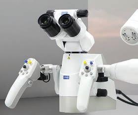
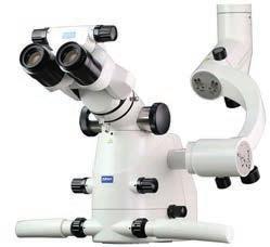
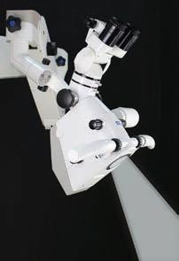
The Dental Operating Microscope (DOM) increases the field of vision and detail observed, essentially allowing the dentist to see things that they would not be able to distinguish with the naked eye. This enables the clinician to operate with a higher level of precision, developing refined motor movements over time. The use of DOM in endodontics provides the clinician with five distinct advantages: magnification, illumination, documentation, patient communication and ergonomics. The DOM provides magnification with a stereoscopic view with the ability to control your level of magnification, either by turning of a dial (Fig. 1a) or automatically by the push of a button on the control handle (Figure 1b).1
Magnification
Microscope magnification in endodontics
1 Peet J. van der Vyver, BChD (Pret); Dip. Odont (Aest Dent); Dip.Odont (Endo); MSc Odont (Endo), PhD (Endo)

2 Martin Vorster, BChD (Pret); PGDipDent (Endo); MSc (Dent)
Unaided vision and even Galilean loupes with an integrated light source do not provide any measurable visual benefits inside the root canal. Most of the time clinicians can only see up to the level of the canal orifice.1 Natural vision also begin to deteriorate at the age of 402 and the lack of awareness of this problem is common amongst dental professionals.3 According to Eichenberger et al,4 and Perrin et al,5 this age related disability can be minimised by the use of loupes or being compensated for by the use of the DOM. Dentistry and especially endodontics, requires precise motor skills along with a high level of visual acuity. Highpowered magnification, such as 4-6 or more times magnification, provides enhanced visual information of the pulp chamber for identification of canal orifices (Fig. 2) compared to either the unaided vision or an entry level 2.5x magnification loupes.6
In various areas of general dentistry, the increased visual information provided by higher magnification eliminates confusion in diagnosis and treatment planning and enhances

24 INTERNATIONAL DENTISTRY – AUSTRALASIAN EDITION VOL.17, NO. 2
Figure 1.(a) Zumax OMS 2360 microscope with manual magnification dial; (b) Zumax OMS 3200 with automatic focus
1a 1b
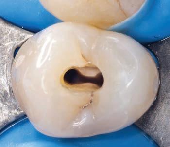
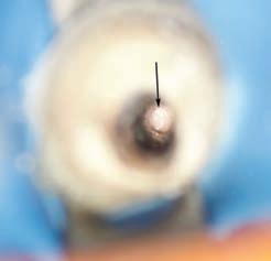
Figure 2. A magnified view (6X) of the pulp chamber floor of a mandibular first molar after root canal preparation. Note the mid-mesial canal (arrow) that was located under magnification before the canal preparation
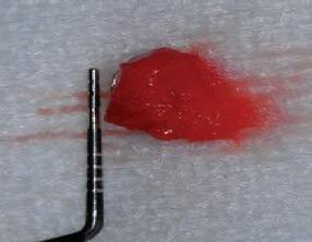
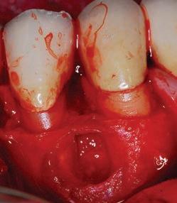
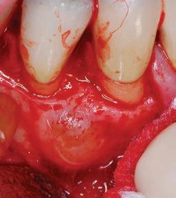
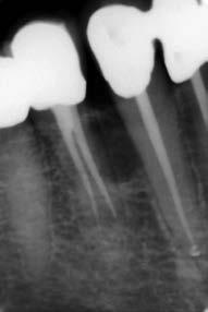
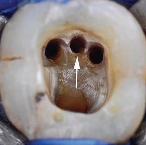
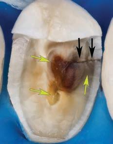
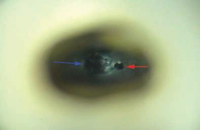
Figure 3. High magnification view (10X) of left maxillary second premolar. Note the different colours on the pulp floor (decay and sclerotic canal orifices)(yellow arrows) and a structural dentine crack originating from distal gingival margin and extending into the direction of the pulp chamber (black arrows)
clinical outcomes compared to the clinical work performed with unaided vision (for example increased longevity of dental restorations). Efficient magnification improves the dentist’s capability to identify caries by inspecting the micro texture and colour of tooth surface. Magnification also aids with the identification and assessment of crack formation in teeth (Fig. 3). 7
Illumination
When magnifying any field of view, the image observed becomes darker because of a decrease in the amount of available light. The DOM can easily be positioned on the operative field with precise focus, utilising the built-in LED coaxial light source directly into the line of vision (Fig. 4). This light source provides excellent illumination and eliminates the formation of shadows resulting in more detail to be observed. It also avoids multiple adjustments unlike the traditional overhead dental operating light or headlamps on loupe systems.
Documentation
Figure 4. Zumax microscope showing the co-axial light direction projected in the line of vision
A built in camera or digital single-lens-reflex (DSLR) camera can be attached to the microscope to enable the clinician to take high quality photos or video in order to document cases or procedures in a step-by step fashion. The DOM allows clinicians to perform this task during the procedure without the need to stop (Fig. 5), move away from the operatory field and pick up a digital camera in order to take photos. Documentation of procedures can be used for patient education, risk management, medico-legal cases and communication with third party funders.
Patient Communication
A picture is worth 1000 words. The live video or captured images from the camera allow patients to observe detail in their mouths giving them a better understanding of their dental problems (Fig. 6). It is further used to explain to patients the complexity of the case with better understanding of the treatment proposed and to demonstrate the final outcome of treatment.
MASTERCLASS
ENDODONTICS INTERNATIONAL DENTISTRY – AUSTRALASIAN EDITION VOL.17, NO. 2 25
IN
Figure 5.(a)Periapical radiograph of a 45 year old patient that presented with a lateral periodontal cyst between roots of the right mandibular canine and first premolar; (b) mucoperiosteal flap was raised; (c) access into the cortical bone plate to expose the cyst; (d) cyst removal and measurement. All the clinical photos were taken during the procedure without the need to stop, move away from the operatory field and pick up a digital camera to record the steps
5a 5b 5c 5d
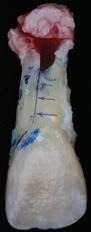
Figure 6. (a) Periapical radiograph showing failure of a revascularization procedure after 6 months on the maxillary left central incisor of a 9 year old patient; (b) photo captured during a surgical procedure that was used to communicate the poor prognosis of a vertical root fracture (black arrows) of the immature root and that the tooth will have to be extracted (c) image of extracted tooth after the fracture line (blue arrows) was stained with methylene blue dye
Ergonomics
The use of loupes and microscopes has been shown to improve clinicians working posture and reduced repetitive stress injuries related to poor posture.8 The DOM forces the clinician to work in an upright neutral position. Brown et al,9 reported in a survey performed amongst general practitioners that the most frequent reason to retire prematurely was musculoskeletal disorders. Studies indicate that more than 50% of those who practice dentistry experience workrelated pain that usually starts during dental school.10
The Use of the DOM in Endodontics
The enhanced vision and illumination of the DOM directly influence the clinician’s field of information in order to make
critical decisions during endodontic treatment. This has a direct effect on outcome and prognosis of the treatment. The following points outlines the importance of magnification during endodontic treatment:
• Identification of structural dentine cracks (Fig.7)
• Diagnosis of secondary caries and leaking restoration margins that can compromise the coronal seal during and after endodontic treatment (Fig.8)
• Preparing more retracted endodontic access cavities (Fig.9)
• Outlining and removing pulp calcifications (Fig.10)
• Identification of missed or additional canal orifices (Fig.11)
• Confirming canal cleanliness after irrigation (Fig.12)
• Managing perforations and tooth resorption lesions (Fig.13)
• Removal of fractured instruments (Fig.14)
• Preparing more conservative osteotomy sites and retrocanal-preparation with ultrasonic instruments for periapical surgery (Fig.15)
Clinical application of different levels of magnification
According to Low, Dom and Baharin,11 magnification in endodontics can be categorised into three levels:
Low Level Magnification (3-8 times)
This level is appropriate for clinical examination of the tooth, positioning of a bur for access cavity preparation or an ultrasonic tip to remove a dentine ledge or pulp calcification and for general root canal instrumentation procedures. The low magnification level with wide field of view, allows the operator the ability for comparison of adjacent anatomic landmarks.
Figure 7. Maxillary left first molar of a 54 year old male patient that presented with irreversible pulpitis. After removal of the previous restoration, two structural dentine cracks (black arrows) were noted and stained with methylene blue to follow the extent and depth into the pulp chamber
Figure 8. Mandibular left second premolar after removal of a previously placed crown. Note the secondary caries on the mesial and distal margins (black arrows) and gutta percha (blue arrow) that was exposed to coronal leakage
MASTERCLASS IN ENDODONTICS 26 INTERNATIONAL DENTISTRY – AUSTRALASIAN EDITION VOL.17, NO. 2
Figure 9. Retracted, conservative access cavity preparation prepared under magnification on a maxillary right first premolar
6a 6b 6c
MASTERCLASS IN ENDODONTICS
Figure 10. Maxillary right first molar after removal of decay and exposure of the pulp. Note the pulp calcifications (black arrow) in the pulp chamber
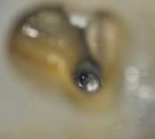
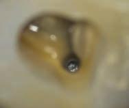
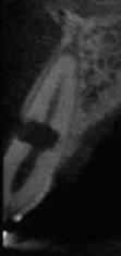
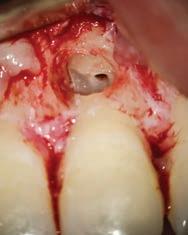
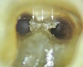
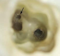
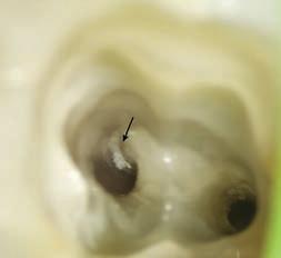
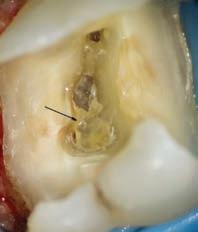
Figure 11. (a)
was
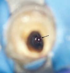
magnification on the buccal aspect of the mesial canal orifice after canal preparation on a mandibular right second molar with a C-shape configuration; (b) after exploring the debris in the groove another canal (black arrow) was located on the lingual aspect of the tooth
Figure 12. Remaining necrotic pulp tissue in an isthmus area (white arrows) after an irrigation protocol was noted under magnification between two distal canals in mandibular right first molar
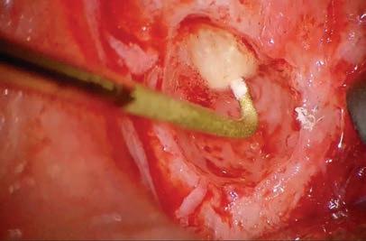
Figure 13. (a) Coronal view of CBCT of a maxillary left central incisor with internal resorption communicating towards the external root surface; (b) lesion was debrided under magnification (15X); (c) Coronal view of CBCT one year after treatment with MTA.
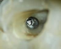
Figure 14. Magnified view of a fractured root canal instrument in the mesiobuccal canal of mandibular left first molar at the beginning of the apical third of the root canal level: (a) Microscope magnification 3X; (b) Microscope magnification 8X; (c) Microscope magnification 19X. Note the excellent detail visible at 19X that will make it easier to plan the management.
surgery. A meta-analysis of endodontic microsurgery showed that the rate of success is higher when done under the DOM.12
High Level of Magnification (16-30 times)
This high level of magnification diminishes the field of view with very narrow depth of field where even minor movements can lead to loss of focus. It is mainly used for identification and following the extend of cracks, identification of canal bifurcations in midroot to apical level and to identify subtle colour variances between secondary and tertiary dentin for canal identification in teeth that present with calcific metamorphoses.
Medium Level Magnification (8-16 times)
Medium level magnification is commonly used for nonsurgical and surgical endodontic procedures as it provides still an acceptable field of view with adequate depth of field. It is mainly used for perforation repair, closing an open apex with MTA, removal of fractured instruments from canals coronal or midroot levels, identification of canal bifurcations in coronal third of the root and for performing apical micro-
Conclusion
The Dental Operating Microscope has gained popularity over recent years and has become the standard of care for endodontics performed by general practitioners and specialists. In this masterclass on magnification, the authors highlights and gives a summary of all the advantages of using magnification in dentistry and more specifically endodontics.
28 INTERNATIONAL DENTISTRY – AUSTRALASIAN EDITION VOL.17, NO. 2
Debris (black arrow)
noted under
Figure 15. Conservative osteotomy site and retro-canalpreparation with ProUltra ultrasonic instrument (Dentsply Sirona).
13a 13b 13c
14a 14b 14c
11a 11b
17a 17b
Figure 17. (a) Magnified view (15X) of a maxillary left central incisor presenting with an open root apex (black arrow); (b) Magnified view (15X) after packing MTA (black arrow) to close the open root apex 18a 18b 18c
(red arrow); (c) postoperative obturation result
References
1. Perrin P, Neuhaus K, Lussi A. The impact of loupes and microscopes on vision in endodontics. Int. Endod. J. 2014;47(5):425-429.
2. Burton J, Bridgman G. Presbyopia and the dentist: the effect of age on clinical vision. Int. Dent. J. 1990;40(5):303-312.
3. Eichenberger M, Perrin P, Ramseyer S, Lussi A. Visual acuity and experience with magnification devices in Swiss dental practices. Oper. Dent. 2015;40(4):E142-E149.
4. Eichenberger M, Perrin P, Neuhaus KW, Bringolf U, Lussi A. Visual acuity of dentists under simulated clinical conditions. Clin. Oral Investig. 2013;17(3):725-729.
5. Perrin P, Ramseyer ST, Eichenberger M, Lussi A. Visual acuity of dentists in their respective clinical conditions. Clin. Oral Investig. 2014;18(9):2055-2058.
6. Doppalapudi N, Burugapalli RK. Benefits of utilization of magnification in dentistry: a review. Dental Research and Oral Health. 2020;3(3):121-128.
7. Mamoun JS. A rationale for the use of high-powered magnification or microscopes in general dentistry. Gen. Dent. 2009;57(1):18-26; quiz 27.
8. Del Fabbro M, Taschieri S, Lodi G, Banfi G, Weinstein RL. Magnification devices for endodontic therapy. Cochrane Database of Systematic Reviews. 2009(3).
9. Brown J, Burke F, Macdonald E, et al. Dental practitioners and ill health retirement: causes, outcomes and re-employment. Br. Dent. J. 2010;209(5):E7-E7.
10. Valachi B. Practice Dentistry Pain-Free: Evidence-based Strategies to Prevent Pain & Extend Your Career. 2008.
11. Low JF, Dom TNM, Baharin SA. Magnification in endodontics: A review of its application and acceptance among dental practitioners. Eur. J. Dent. 2018;12(04):610-616.
12. Setzer FC, Kohli MR, Shah SB, Karabucak B, Kim S. Outcome of endodontic surgery: a meta-analysis of the literature—part 2: comparison of endodontic microsurgical techniques with and without the use of higher magnification. J. Endod. 2012;38(1):1-10.
MASTERCLASS IN ENDODONTICS 30 INTERNATIONAL DENTISTRY – AUSTRALASIAN EDITION VOL.17, NO. 2
Figure 18. (a) Periapical radiograph showing the lingual canal detection in the midroot level of a mandibular left first premolar; (b) the orifice of the second canal was located under magnification (19X) after a dentine ledge was removed with an ultrasonic tip. Note the main buccal canal (blue arrow) and the located orifice of the lingual canal
Figure 16: Low level magnification (8X): Removing restrictive dentine in the canal orifice of a mandibular second molar with a C-Shaped canal configuration.
Simple adhesive luting in everyday practice
José Ignacio Zorzin1
1
P.D. Dr. med. Dent
Research Assistant and Dentist, Dental Clinic 1 (Preventive Dentistry and Periodontology), University Hospital of Erlangen, Germany
Introduction
Self-adhesive resin cements facilitate the adhesive bonding of indirect restorations. When using these materials, no pre-treatment of the hard tooth substances is necessary. Self-adhesive resin cements have a wide indication spectrum, but in everyday practice you have to resort to conventional adhesive cementation in some cases. As a result, you have to procure both a self-adhesive cement and a conventional composite cement and select your cement per case. Universal self-adhesive resin cements are an interesting solution to this problem. They can be used as self-adhesive resin cement and - in combination with an associated primer - also as a conventional adhesive resin cement.
The following clinical cases show the possibilities of using a universal self-adhesive resin cement (G-CEM ONE, GC Europe). The first case shows the self-adhesive cementation of a monolithic zirconium oxide bridge and the second case the conventional adhesive cementation of two lithium disilicate inlays (Initial LiSi Press, GC Europe).
Case 1
The endodontically treated tooth 24 had to be extracted due to a root long fracture. It was decided to fill the gap by means of a three-unit monolithic zirconia bridge. After adhesive restorative therapy of abutment teeth 23 and 25, these teeth were prepared with an isogingival finish line (chamfer). After taking the impression, a provisional restoration was made, luted with a eugenol-free, temporary cement (Freegenol, GC Europe) and cleaned (Fig. 1). No eugenol-containing cement should be used to fasten the provisional restoration, as eugenol impairs the polymerization and adhesion of adhesives and composites.
After completion, the monolithic zirconia bridge was inserted (Fig. 2). For this purpose, the temporary solution was removed and then all remains of the luting cement were removed with a scaler and a polishing cup with pumice slurry (Fig. 3). The colour effect, accuracy of fit and occlusion of the bridge were checked (Fig. 4). Prior to adhesion, all intaglio surfaces of the restoration must be clean and slightly roughened. Saliva, in particular, adheres very strongly to the oxide ceramic due to its polarity and must be thoroughly removed. Cleaning with alcohol is unfortunately ineffective and phosphoric acid is absolutely contraindicated. In the case of zirconium oxide, the adhesive surfaces are cleaned and roughened after the try-in by sandblasting with aluminum oxide powder (35 µm grit) at low pressure (approx. 1.5 bar). Ideally, this is done chair-side (e.g. Airsonic Mini Sandblaster, Hager and Werke). For this purpose, it is advisable to mark the surfaces to be treated, as in the present case, with a waterproof felt-tip pen (Fig. 5) before they are sandblasted (Fig. 6). Alternatively, if the restoration has already
CLINICAL 32 INTERNATIONAL DENTISTRY – AUSTRALASIAN EDITION VOL.17, NO. 2
José Ignacio Zorzin
been roughened in the laboratory, you can use a restoration cleaner after the try-in (e.g. Ivoclean, Ivoclar Vivadent or Katana Cleaner, Kuraray Noritake).
Before the relative isolation of the work area, with cotton rolls and parotid absorbent pad, the tooth abutments were cleaned again and then checked for contamination with saliva and blood. For insertion with the self-adhesive resin cement, the dentine must not be overdried, but must appear semi-moist. In this case, a “re-wetting” was necessary. For


this purpose, a microbrush was sprayed from a distance with air-water spray. With the microbrush prepared in this way, the tooth was moistened.

In order to prevent premature light polymerization of the self-adhesive resin cement during insertion, the ambient light was reduced. Then, G-CEM ONE was applied on the inner crown surfaces (Fig. 7a and b) and the bridge was inserted with strong pressure (Fig. 8).
The tack-cure technique was used for the clean-up. For this
CLINICAL INTERNATIONAL DENTISTRY – AUSTRALASIAN EDITION VOL.17, NO. 2 33
Fig. 1: Temporary restoration from teeth 23 to 25 Fig. 2: Monolithic zirconia bridge to be luted
Fig. 3: Abutment teeth 23 and 25, thoroughly cleaned
Fig. 4: Try-in of the restoration
Fig. 5: The intaglio surface was marked with a black felt-tip pen as a visual control
6a 6b 5a 5b
Fig. 6: After sandblasting the intaglio surface, the black marking had entirely disappeared
7a 7b
Fig.
purpose, the light guide of the curing light was waved over the excess cement for 1 second (Fig. 9) until it reached a rubber-like consistency. The hardened excess cement could be easily removed with a scaler (Fig. 10). Reaching a good consistency for excess cement removal depends on the lightcuring unit being used. Therefore, one should practice in advance to find the best combination of time, intensity, and distance of the curing light in use.

After complete removal of the excess cement, the adhesion, occlusion and articulation movements were checked (Figs. 11 and 12).


ZORZIN
34 INTERNATIONAL DENTISTRY – AUSTRALASIAN EDITION VOL.17, NO. 2
Fig. 7: Cementation with the universal self-adhesive resin composite G-CEM ONE (GC Europe)
Fig. 8: Insertion of the bridge with strong pressure
Fig. 9: Tack-curing the excess cement for 1 s to give it an instant rubbery consistency
10: Excess removal with a probe
Fig. 12: Vestibular view after cementation
Fig. 11: Occlusal view after cementation
Fig. 13: Deficient restorations on teeth 46 and 47
Fig. 14: After removal of the caries and the old restorations

Case 2
During a check-up, it was found that the restorations on teeth 47 and 46 were deficient (Fig. 13). Under local anesthesia and rubber dam isolation (isodam, Sigma Dental Systems), the restorations and caries were removed. Using the rubber dam has several advantages in this clinical situation: increased patient comfort, infection prophylaxis for


the treatment team, a perfect overview and thus time-saving. Due to the pronounced oro-vestibular expansion of the cavities in the approximate region, it was decided to restore the teeth indirectly with glass-ceramic restorations (Fig. 14).

A two-bottle universal adhesive (G2-BOND Universal, GC Europe) was applied to the dentine portions of the cavities (self-etch mode; Fig. 15), gently blown and light-cured (Fig. Fig. 16: Light-curing


ZORZIN 36 INTERNATIONAL DENTISTRY – AUSTRALASIAN EDITION VOL.17, NO. 2
15: Application of the two-step adhesive G2-BOND Universal 15a 15b
17: After cavity preparation for indirect glass
restorations
18: Inlays
18a 18b Fig. 19: Try-in of the inlays
20: The restorations were etched with hydrofluoric acid
21: Preparing the restoration surface to be bonded with G-Multi PRIMER 21b 21a
22: Selective enamel
23:
to be bonded with
of the adhesive Fig.
Fig.
ceramic
Fig.
made from Initial LiSi Press
Fig.
Fig.
Fig.
etching Fig.
Preparations after etching Fig. 21: Preparing the restoration surface
G-Multi PRIMER

24a
24b
Fig. 26: Seating of the inlay
Fig. 27: Excess removal with a probe

Fig. 28: Light-curing of all margins
Fig. 29: After finishing of the margins
16). Finally, undercuts and irregularities were blocked using a composite (G-ænial Universal Injectable A3, GC Europe) and the cavities were prepared (Fig. 17). An impression was made using the two-step technique and provisionals were made. These were, as described above, luted with a eugenolfree, provisional cement (Freegenol) and cleaned.
The restorations were made from a lithium disilicate press ceramic and characterized (Initial LiSi Press, shade A3-MT and Initial IQ Lustre Pastes ONE, GC Europe; Fig. 18).
After having removed the provisional restorations and having thoroughly cleaned the cavities, the restorations were


Fig. 30: Immediately after removal of the rubber dam. The teeth are still slightly dehydrated.
tried in and checked for fit and aesthetics (Fig. 19). This should be done under rubber dam to minimize the risk of incidental aspiration and to protect the ceramic from damage if the patient would bite on it. Evidently, the aforementioned good reasons for rubber dam remain also valid.
After the try-in, the adhesive surfaces of the inlays were etched with 5% hydrofluoric acid for 20 seconds (IPS Ceramic Etching Gel, Ivoclar Vivadent; Fig. 20). Etching creates a clean surface with a retentive micro-relief. To reconcile the hydrophilic glass ceramic with the rather hydrophobic resin cement, the etched surfaces were silanized with a universal
ZORZIN
38 INTERNATIONAL DENTISTRY – AUSTRALASIAN EDITION VOL.17, NO. 2
Fig. 25: The preparations are ready for cementation
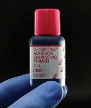
Fig. 24: Application of G-CEM ONE Adhesive Enhancing Primer ensures immediate high bond strength
primer (G-Multi PRIMER, GC Europe, Fig. 21).
After pre-treatment of the restorations, the enamel surfaces of the cavity were etched with 35% phosphoric acid gel for at least 15 sec. (Fig. 22), then thoroughly rinsed with water spray and dried with compressed air (Fig. 23). Due to the glass-ceramic and the non-(macro)retentive preparation, the adhesive attachment of the inlays was carried out with the universal self-adhesive resin cement in combination with its corresponding primer (G-CEM ONE and G-CEM ONE Adhesive Enhancing Primer, GC Europe). The primer was applied with a brush to the prepared enamel and dentine surfaces (Fig. 24, left to rest for 10 s and dried for 5 s at maximum air pressure (Fig. 25). At this time, the intensity of the operation light and ambient light was reduced to prevent premature setting of the universal self-adhesive resin cement. The Adhesive Enhancing Primer contains a chemical initiator for G-CEM ONE. When G-CEM ONE comes into contact with the primer, the setting reaction is accelerated. For this
reason, the inlay was first seated on tooth 47 (Fig. 26) and thereafter the inlay on 46. After insertion, the cement was tack-cured as described above. The excess cement was thoroughly removed (Fig. 27) and then extensively light-cured (Fig. 28). Before removing the rubber dam, the margins were finished with polishing discs (Sof-Lex, 3M) and polishing strips (Epitex, GC Europe) (Fig. 29). After removal of the rubber dam, the occlusion and articulation check was carried out (Fig. 30).
Conclusion
The presented cases show how - with a universal selfadhesive resin cement - indirect restorations can be attached in a self-adhesive as well as conventional adhesive manner. Hence, universal self-adhesive resin cements simplify adhesive cementation in everyday practice.
Reprinted with permission GC get connected
ZORZIN
INTERNATIONAL DENTISTRY – AUSTRALASIAN EDITION VOL.17, NO. 2 39


Explore over 270 hours of clinical and business related content all in one place with access to
Business Booster Panel Discussion
FREE Webinar READ MORE READ MORE
7 CPD Credit
Why you should use Reveal Clear Aligners
|
READ MORE READ MORE
CPD COURSES AND EVENTS YOUR FREE GO-TO RESOURCE FOR DEN TAL EDUC ATION AND CPD
Dr Gordon Christensen Clinical Courses Dr. Gordon J. Christensen Access courses online until January 2023
Hosted by Mike Covey Wednesday 2 November
Insight Hyaku100
Saturday 18 February 2023
Dr Bruce McFarlane 1 CPD Credit
FREE Webinar Monday 7 November
UPCOMING
UPCOMING
Dr. Felix Wöhrle 1 CPD Credit | FREE Webinar Thursday 10 November


dentaleducationhub.com.au
courses, webinars, podcasts and articles. View our upcoming courses and webinars below.
CPD COURSES AND EVENTS
FREE GO-TO RESOURCE FOR DEN TAL EDUC ATION AND CPD
bio-design with
YOUR
Zirconia
KATANA
Learn how 3D printing is redefining chairside dentistry | VIC Jeroen Klijnsma 5 CPD Credits | $450 Wednesday 9 November READ MORE READ MORE
Daniele Rondoni 1 CPD Credit | FREE Webinar Tuesday 8 November
Minimally invasive veneer preparation & full mouth rehabilitation
Implant CPD ‘BITES’ WA Tabitha Acret 1.5 CPD Credits Thursday 17 November READ MORE READ MORE
Treatment of a young patient with zirconia veneers

 Daniele Rondoni1 and Enzo Attanasio2
1 Daniele Rondoni, MDT Savona, Italy
2 Enzo Attanasio, DDS Lamezia Terme, Italy
Veneers made of zirconia? In some cases, like the one presented below, monolithic zirconia veneers may be an option. Reasons for selecting a latest-generation zirconia such as “KATANA™ Zirconia” YML include its very high trunslucency and a wall thickness of only 0.3 to 0.4 mm supporting minimally invasive tooth preparation. Due to highly automated production procedure, the manual effort involved may be reduced, while highly asthetic outcomes are possible.
Figure 1: Initial situation: Young female patient with misshaped and misaligned maxillary incisors.
Figure 2: Digital smile design revealing the ideal proportions and positions of the anterior teeth.
Figure 3: Ideal tooth proportions and positions displayed over a picture of the teeth after orthodontic treatment and the creation of a mock-up. The positions are ideal and the tooth shapes obtained with the mock-up only need some minor adjustments.
Figure 4: Detailed view of the maxillary teeth with the ideal shapes blended in. The decision is made to produce six veneers made of “KATANA™ Zirconia” YML for definitive treatment.
42 INTERNATIONAL DENTISTRY – AUSTRALASIAN EDITION VOL.17, NO. 2
CASE REPORT
Figure 5a: Digital impression of the maxillary teeth with mock-up imported into the design software.


Figure 5b: Digital model of the maxilla in the CAD software with full-contour veneers designed for the incisors and canines according to the ideal shapes planned with digital smile design.
Figure 6a: Occlusal view of the virtual model.
Figure 6b: Occlusal view of the model with the designed veneers.
Figure 7a: Facial view of the patient with the mock-up in place.
Figure 7b: Facial view of the patient with the planned veneers blended in.
INTERNATIONAL DENTISTRY – AUSTRALASIAN EDITION VOL.17, NO. 2 43
CASE REPORT
Figure


44 INTERNATIONAL DENTISTRY – AUSTRALASIAN EDITION VOL.17, NO. 2
RONDONI / ATTANASIO
Figure 8: Guided tooth structure removal with the aid of a silicone index. The minimum wall thickness of the selected material“KATANA’” Zirconia” YML- is 0.4 mm.
9: Maxillary teeth immediately after minimally-invasive tooth preparation.
Figure 10: Matched digital impressions of the maxilla and mandible taken after the tooth preparation.
Figure 11: Digital impression: occlusal view of the maxillary teeth.
Figure 12: Virtual veneers ready to be milled.
Figure 13: Pre-sintered veneers made of “KATANA™ Zirconia” YML.
Figure 14: Zirconia veneers on the resin model after sintering.
Figure 15: Monolithic zirconia restorations on the resin model after the 7-hour final sintering.

Figure
Figure


46 INTERNATIONAL DENTISTRY – AUSTRALASIAN EDITION VOL.17, NO. 2
RONDONI / ATTANASIO
Figure 16: Frontal view of the master cast with the six veneers individualized with the liquid ceramic system CERABIEN’” FC Paste Stain.
Figure 17: Lateral view of the veneers on the master cast.
18: Tooth-like translucency of the veneers on the model.
19: The minimal wall thickness of 0.4 to 0.6 mm and the positioning of the veneers in the upper (enamel) part of the blank are responsible for this effect.
Figure 20: Veneers made of “KATANA’” Zirconia” YML ready for try-in.
Figure 21: Intra-oral try-in with two different shades of the “PANAVIA’” V5” Try-in Paste: A2 is used in the right and Clear in the left quadrant.
Figure 22: Cleaning of the tooth structure with pumice paste after try-in.
Figure 23: Thorough rinsing with water to remove any paste residues.

Figure 24: Etching of the prepared tooth structure with phosphoric acid etchant.
Figure 25: Clean, isolated central incisors ready for adhesive cementation.

Figure 26: Sandblasting of the veneer’s intaglio with alumina oxide (particle size: 50 μm, pressure: 2 bar). This kind of surface conditioning treatment is recommended for zirconia, as it creates the desired micro-retentive surface structure favourable for adhesive bonding1

Figure 27: Application of “CLEARFIL™ CERAMIC PRIMER” PLUS to the bonding surface of the veneers (followed by mild airdrying).
Figure 28: Treatment of the etched tooth structure with “PANAVIA™ V5” Tooth Primer (followed by mild air-drying).
Figure 29: Application of “PANAVIA™ V5” Paste (shade A2) to the bonding surface of the veneers.

48 INTERNATIONAL DENTISTRY – AUSTRALASIAN EDITION VOL.17, NO. 2
RONDONI / ATTANASIO
Figure 30: Close-up view of the restoration margin during cementation. Working field isolation is a key success factor of adhesive procedures.

Figure 31: Lateral view of the cemented veneers. The result is a natural surface texture, which contributes to a natural appearance of the restorations.
Figure 32: Frontal view of the veneers in place.
Figure 33: Treatment outcome immediately after rubber dam removal.
Figure 34: Treatment outcome with healthy soft tissues two weeks after treatment.
References
1 Nishigawa G, Maruo Y, Irie M, Maeda N, Yoshihara K, Nagaoka N, Matsumoto T, Minagi S. Various Effects of
Figure 35: Gums are healthy and the restorations show a great optical integration with the adjacent posterior teeth.


Sandblasting of Dental Restorative Materials.
PLoS One. 2016 Jan 14;11(1):e0147077.
RONDONI / ATTANASIO INTERNATIONAL DENTISTRY – AUSTRALASIAN EDITION VOL.17, NO. 2 49
Aerosol reduction by means of an intraoral spray mist suction – first findings from an experimental pilot study
Martin Koch1
1Dr. Martin Koch
DÜRR DENTAL SE
Höpfigheimer Str. 17 74321 Bietigheim-Bissingen martin.koch@duerrdental.com
Introduction
To the best of our current knowledge, SARS-CoV2 is transmitted primarily through aerosols and droplets. Aerosols are defined as suspensions of solid or liquid particles in a gas, such particles having a diameter of less than 5 µm. Particles larger than 5 µm are described as droplets. In practice, however, the transition is a gradual one since the process of evaporati-on can turn droplets into aerosols. In the examination that follows, the term „particle“ is therefore used for both size groups.
Dental personnel are more exposed to infection through aerosols and droplets. Aerosols and droplets are produced when dental instruments are used during treatment. Various rotating instruments (turbines, straight and contra-angle hand pieces) and ultrasonic instruments (scalers) are cooled by water. A cooling jet hits the surface of the tooth at high speed and rebounds as spray mist. Spray mist is also produced by powder jet instruments.
A powder-water mixture is blasted onto the surface of the tooth using compressed air, and then rebounds. As well as water and solid particles, the spray mist also contains potentially infectious agents in the patients blood and saliva. The infection potential of these dental aerosols has been described and supported in technical literature many times. From the evidence available, transmission of SARS-CoV2 through dental aerosols and droplets cannot be ruled out.
As early as 1971, Davis et al. (Br. Dent. J, 130, 483), showed that a better aerosol reduction can be achieved using intraoral suction at a high flow rate (300 l/min) and a low vacuum than at a low flow rate. In Europe, this suction philosophy (high flow rate at low vacuum) has become the accepted gold standard. In many other countries, procedures are still performed using low flow rates (e.g. saliva ejector) and a high vacuum.
From a risk minimisation perspective, it must be possible to precisely measure the performance of dental intraoral suction solutions. This pilot study therefore examined the efficiency of intraoral suction relating to a reduction in the number of particles leaving the mouth.
WHITE
50 INTERNATIONAL DENTISTRY – AUSTRALASIAN EDITION VOL.17, NO. 2
PAPER
The following methodical steps were taken:
1. Characterisation of particle emission without intraoral suction and optimisation of the examination setup
2. Influence of the suction system on particle reduction
3. Influence of the suction system on suction power (flow rate)
4. Influence of the flow rate on particle reduction
5. Influence of the suction position on particle reduction Again from a risk minimisation perspective, a sub-optimal intraoral suction technique at a distance of 5 cm from the preparation point was selected for examinations 2 and 4.
Methodology
In this study, an imaging process (so-called shadow imaging) was used for the quantitative determination of particle emissions in an in-vitro model (mannequin). The particle emissions were compared during preparation with a turbine (Super-Torque LUX 3 650 B (KaVo), 400,000 rpm, 58 ml/ min water) by using various intraoral suction solutions. The suction power, the hose diameter, the suction system and the suction position were altered. A powerful spray mist suction system (model Variosuc, Dürr Dental, max. flow rate 370 l/min) and a Venturi system (Belmont) were employed as the suction system. The suction power (flow rate) was controlled by means of a slide on the suction handpiece. Moreover, various suction cannula (saliva ejector (Henry Schein), universal cannula Protect (Dürr Dental), universal cannula Petito (Dürr Dental), aerosol cannula (Dürr Dental)) and suction handpiece (large suction handpiece (Dürr Dental), small suction handpiece (Dürr Dental), stainless steel handpiece (A-dec)) were used. The flow rate (l/min) was

measured at the cannula using a float volume flowmeter (ROTA G 4.4000 SW=N4 10x).
The particle emission was measured by the shadow imaging technique (ParticleMaster, Lavision) with pulsed background lighting (image frequency 12.95 Hz, pulse duration of the light source: 0.4 µs, shooting method: Double frame mode with an exposure time of 42 µs; interval between 2 images: 10 µs). Each measurement involved analysing 127 single images (measurement time 10 s) using the DaVis software solution (Lavision, Version 10.1.1.60438) in a frame of 6.6 x 5.3 x 1.1 mm. Particles larger than 50 µm were not included in the analysis because, as large drops, they fall rapidly and are of little significance for the transmission of infection through droplets and aerosols.
The following measurement parameters were recorded:
– Particle count [p/s]: Number of particles measuring between 5 µm and 50 µm that pass through the frame
– Velocity [m/s]: Velocity of the particles that pass through the frame
– MVF [µg/s*cm³]: Mass volume flow of the particles per second (calculation where density =1)
– Reduction rate [%]: Particle emission with suction in relation to particle emission without suction (flow rate = 0 l/min) relative to the MVF
The measurement setup was chosen so as to generate a reproducible spray mist in a vertical direction towards the operator and to prevent this being deflected by the cheek. This was the case when preparing tooth 14 on the buccal side in the upper jaw. The instrument was located immediately above

WHITE PAPER INTERNATIONAL DENTISTRY – AUSTRALASIAN EDITION VOL.17, NO. 2 51
Dental aerosol, produced on the surface of the tooth as the cooling jet rebounds when a turbine is used.
Measurement setup with unit for background lighting on the left and lens on the right, close to the head. The optical frame is located 5 cm above tooth 11.
Analysis of a single image using imaging software. 7 particles measuring between 5.4 μm and 74 μm were detected.

the surface of the tooth, thereby preventing the removal of any tooth substance. The head was stretched on. The lens was positioned to allow the spray mist to flow through the frame unhindered (5 cm above tooth 11).
Each measurement involved analysing 127 single images (measurement time 10 s) using the imaging software and determining the number of particles and the velocity of each individual particle. Each measurement was repeated at least 3 times and the average calculated.
Results
Characterisation of particle emission
In the spray mist of a turbine, a large number of particles measuring between 5 µm (resolution limit) and 75 µm can be detected at a distance of 5 cm using the shadow imaging technique (see Fig.). 99% of the particles measured less than 50 µm. The maximum velocity of the particles was 0.7 m/s. Because, as drops, large particles fall rapidly and are of little significance for the transmission of infection through droplets and aerosols, particles larger than 50 µm were not included in the analysis during subsequent measurements.
Influence of the suction system on particle reduction
The suction cannula was positioned sub-optimally on the buccal side of tooth 34. The distance to the preparation site on tooth 14 was 5 cm. The influence of various suction system
components on aerosol reduction was examined when the spray mist suction system was operating at maximum capacity.
Various cannula shapes and diameters, various suction hoses and handpieces, as well as a Venturi suction system, were examined in the following combinations:
CU 16: Large suction hose, large suction handpiece, universal cannula Protect 16 mm
CP 16: Large suction hose, large suction handpiece,
Size distribution of the particles in a spray mist cloud caused by a turbine.

WHITE PAPER
52 INTERNATIONAL DENTISTRY – AUSTRALASIAN EDITION VOL.17, NO. 2

universal cannula Petito 16 mm
CA 16: Large suction hose, large suction handpiece, aerosol cannula 16 mm
SE: Saliva ejector hose, small suction handpiece, saliva ejector
CU 11: Saliva ejector hose, stainless steel handpiece, universal cannula Protect 11 mm
CU 11-16: Saliva ejector hose, stainless steel handpiece, 11-16 mm adapter, universal cannula Protect 16 mm
VU 16: Venturi suction system, large suction hose, large suction handpiece, universal cannula Protect 16 mm
The suction hose, suction handpiece and suction cannula had an enormous influence on the reduction rate of the emitted particles. The combination of „large suction hose and powerful suction system (Variosuc, Dürr Dental)“ resulted in an aerosol reduction rate of almost 100%. Where cannula with a large diameter were used (universal cannula, aerosol cannula, Dürr Dental), no particles measuring between 5 µm and 50 µm were detectable in the frame during the measurement time of 10 s. The result was not the same for a Venturi suction system. In this case, numerous large particles were detectable by the „large suction hose and large suction cannula“ combination.
The saliva ejector customarily used in dentistry was unable

to suction off the aerosols completely. Over 300 particles per second were still detectable.
All examination approaches using the small saliva ejector hose resulted in an increased particle count within the measurement range. The insufficient suction power produced a visually observable accumulation effect of the particle cloud in the frame. This resulted in an increase in the particle count in the frame due to the measuring technical and, arithmetically, in a negative particle reduction.
Influence of the suction system on suction power (flow rate)
The influence of various suction system components on the flow rate was examined. The suction power of the Variosuc spray mist suction system used amounted to a maximum of 370 l/min.
The use of various hose diameter, suction handpieces and suction cannula reduced the flow rate at the suction cannula. The smaller the cross-sections, the lower the flow rates achieved at the cannula. The poorest suction power, at 70 l/min, was achieved by the saliva ejector.
When the same components were selected (suction handpiece, suction cannula), the Venturi suction system
WHITE PAPER 54 INTERNATIONAL DENTISTRY – AUSTRALASIAN EDITION VOL.17, NO. 2
Use of various components, from left to right: CU 16, CP 16, CA 16, SE, CU 11, CU 11-16

achieved only 48% of the suction power compared to the spray mist system from Dürr Dental.

Influence of the flow rate on particle reduction
The suction cannula was positioned sub-optimally on the buccal side of tooth 34. The distance to the preparation site on tooth 14 was 5 cm. The flow rate was set to between 100 l/min and 330 l/min by means of a slide on the large suction handpiece. Three different 16 mm suction cannula
were examined: Universal cannula Protect, universal cannula Petito and aerosol cannula (all Dürr Dental).
Without intraoral suction (flow rate 0 l/min), an average of 480 particles per second were detectable in the frame. At a flow rate of up to 200 l/min, the particle count per second rises initially. This results in the negative reduction rate of the emitted particles. The process of intraoral suction causes the particles to slow down. This produced a visually observable accumulation effect of the particle cloud in the frame. By contrast, from a flow rate of 270 l/min, no particles measuring between 5 µm and 50 µm were detectable in the frame during the 10 s measurement time with any of the three suction cannula examined. Under the measurement conditions selected, this is equal to a reduction rate of 100%.
Influence of the suction position on particle reduction
The flow velocity of the counterflow generated by the intraoral suction process decreases rapidly as the distance to the suction cannula increases. The examination was therefore repeated with an optimal suction technique (1 cm distance to the preparation point on 14) and the results compared to those achieved by a sub-optimal suction technique.
Sub-optimal suction
Dependence of particle reduction on the intraoral suction flow rate with various 16 mm suction cannula. CU 16: Large suction hose, large suction handpiece, universal cannula Protect 16 mm, CP 16: Large suction hose, large suction handpiece, universal cannula Petito, 16 mm, CA 16: Large suction hose, large suction handpiece, aerosol cannula 16 mm

With sub-optimal suction, particles were detectable in the frame up to a flow rate of 250 l/min. At optimal suction power, the value shifts towards lower flow rates. The efficiency of an intraoral suction process was able to be optimised through an optimal suction technique (short distance). From a flow rate of ≤200 l/min, a particle reduction was no longer possible in the examinations.

WHITE PAPER
56 INTERNATIONAL DENTISTRY – AUSTRALASIAN EDITION VOL.17, NO. 2
Examination setup with sub-optimal suction position using the universal cannula Protect suction cannula. The flow rate was set by means of the slide on the suction handpiece

Examination setup with optimal suction position using the universal cannula Protect suction cannula. The flow rate was set by means of the slide on the suction handpiece.
Discussion
An intraoral suction process generates a counterflow, which in turn slows down the emitted particles. Ideally, the intraoral suction is so strong that the particles do not leave the mouth region and are suctioned off through the suction cannula. The physical variable is the flow velocity v [cm/s]. According to v = f / d (where d = diameter in cm² and f = flow rate in cm³/s) this increases as the flow rate increases. The flow rate at the suction cannula is therefore the crucial physical variable for the reduction of dental aerosols.

The graphic summarises all the measurement results achieved in this pilot study and highlights the correlation between flow rate and particle reduction.
From a flow rate of 270 l/min, an intraoral suction process is able to reduce particle emissions during the preparatory work using a turbine to below the detection limit. These high flow rates can be achieved with the suction components (large diameter) and powerful suction systems (high flow rate) that have been routinely used in Europe for decades. A flow rate of less than 200 l/min is not enough to prevent particle emission. Even an optimised suction technique does not result in improved particle reduction in this case. It would appear that the velocity of the counterflow is to insufficient for suctioning off the particles. At flow rates of between 200 l/min and 250 l/min, a good suction technique can optimise the effect of the suction process.
Disclaimer:
Dr Martin Koch is employed by Dürr Dental SE, Germany
Comparison of the particle reduction rate with sub-optimal and optimal suction techniques depending on flow rate

Dependence of particle reduction on the intraoral suction flow rate with various intraoral suction solutions. CU 16: Large suction hose, large suction handpiece, universal cannula Protect 16 mm, CP 16: Large suction hose, large suction handpiece, universal cannula Petito, 16 mm, CA 16: Large suction hose, large suction handpiece, aerosol cannula 16 mm, CU 11: Saliva ejector hose, stainless steel handpiece, universal cannula Protect 11 mm, CU 11-16: Saliva ejector hose, stainless steel handpiece, 11-16 mm adapter, universal cannula Protect 16 mm, VU 16: Venturi suction system, large suction hose, large suction handpiece, universal cannula Protect 16 mm.

Further reading:
Spray mist reduction by means of a high-volume evacuation system - Results of an experimental study
Martin Koch, Christian Graetz (2021) PLoS ONE 16(9): e0257137
https://doi.org/10.1371/journal.pone.0257137
WHITE PAPER 58 INTERNATIONAL DENTISTRY – AUSTRALASIAN EDITION VOL.17, NO. 2

COLTENE HYSOLATE LATEX DENTAL DAM GC RELINE II
HySolate Latex Dental Dam is made of pure, natural rubber latex and is powder free.
Powder free, low protein Dental Dam is a simple and clever measure to reduce the risk of developing latex hypersensitivity. Latex Dental Dam provides strong retraction. HySolate Dental Dam is available in a comprehensive variety of colours and sizes (5”x5” (127 x 127 mm) and 6”x6” (152 x 152 mm))

• The lighter colours have the advantage of naturally illuminating the operating field whereas the darker colours can help with visual contrast.
• Powder free, low protein latex dam reduces the risk of developing latex hypersensitivity
• Increased visibilit y on the treatment site through isolation
• Acts as an infection control barrier
• Creates a dry operating field
• HySolate black Dental Dam has the template for marking the tooth position printed on. This saves the working step of marking the dam before punching.
DURR DENTAL MYLUNOS®
Carefully coordinated prophylaxis products and the fully machine-preparation-capable powder jet handpiece MyLunos®, with unique interchangeable chambers, are the perfect solution for an especially efficient and noticeably more relaxed practice workflow.
Lunos Handpiece - Supragingival and Subgingival Air-polishing


• Supra & Perio Nozzle
• Sterile single -use perio tip (sold separately, 40 pack refills)
• Exchangeable powder chamber
• 5 coupling t ypes
• Fully re-processable
Lunos Prophy Powder
• Prophy Powder for supragingival application – Neutral and Orange
• Perio-Combi for sub & supragingival application - particle size of ~ 30 µm, it subgingivally removes the biofilm and is significantly more comfortable for patients.

• Mucous membranes are not irritated and do not dry out
GC RELINE II is a soft denture relining material designed for denture wearers who cannot tolerate conventional hard acrylic. Reline II is well suited for patients exhibiting thin, relatively non-resilient mucosa or severe alveolar bone resorption and dentures supported by implants after the healing phase, as well as, immediate dentures after extractions. GC Reline II’s new vinylpolysiloxane (VPS) formula exhibits improved adhesive characteristics as well as better grinding performance in clinical practice*. GC Reline II may be used with printed resin and metal-based dentures when applied as directed with the accompanying Primer. The GC Reline II Introductory Kit includes one liner material cartridge, primer, remover, trimming point, finishing wheel, mixing tips, plastic spatula, disposable brushes, and a technical guide. This product is available in Soft, Extra Soft, and Extra Extra Soft versions; individual refills for each kit are available.
*Daisuke et al (2015). Peel Bond Strength of Silicone Denture Relining Materials. J Dent Res 94 (Spec Iss A ):3487. https://iadr.abstractarchives.com/ abstract/15iags-2108504/peel-bond-strength-of-silicone-denture-relining-materials
HALO SECTIONAL MATRIX SYSTEM
The Halo Sectional Matrix System produces anatomically shaped contours so you can spend less time shaping and finishing your restoration. And it provides consistently tight contacts, helping to ensure that your restoration will have the longevity both you and your patient expect.
Maximum tooth separation is achieved through the force of the nitinol ring and the active wedging provided by the Halo Wedges. This ideal system of separation allows you to restore a single tooth or back-to-back restorations with ease.
All products available from: HENRY SCHEIN • Tel: 1300 65 88 22 • www.henryschein.com.au

PRODUCTS 60 INTERNATIONAL DENTISTRY – AUSTRALASIAN EDITION VOL.17, NO.2
EXCLUSIVELY FROM HENRY SCHEIN SIERRA DENTAL TOOLS Advantages • High quality CADCAM Milling Burs on the market • Long lasting, low tool cost per unit • Less labour cost changing burs • Better surface finish • Made in the USA Product Offering • Dentsply Sirona Imes Icore • Amann Girbach Ivoclar • VHF Arum Applications • Zirconia • Wax and PMMA • Glass ceramics • Metal
OPALESCENCE™ WHITENING TOOTHPASTE JIFFY™ ONE SINGLE-USE POLISHERS
Jiffy One single-use polishers are disposable dental polishers designed to polish any composite material effectively and quickly.

With Jiffy One polishers there is no need for re-processing or sterilisation, as they can be safely and conveniently discarded after use. Specially formulated with Ultradent’s advanced diamond grit, Jiffy One polishers can deliver a smooth, high-quality polish in only one or two steps. Available in cups, points, and disks and in medium or fine grit, the Jiffy One system is simple and convenient.
PARKELL DIGITEST 3 PULP VITALITY TESTER
The Digitest 3 electrically stimulates the tooth to test for vitality.


Comparing the response to the stimulus of the suspected tooth with a known healthy tooth’s response to an identical stimulus helps find the source of the patient’s pain.
Dentists worldwide routinely diagnosing and treating problematic teeth.
• Single tooth testing
• Intuitive single button operation
• Multiple test settings to accommodate your personal preference
• Self-calibrating for quick easy setup
• Ergonomic design
• Four autoclavable probes (included) promote easy access to all tooth surfaces


• Standard 9V battery enables simple in-office replacement
Opalescence Whitening Toothpaste is an easy and effective way to maintain a bright, white smile. The Opalescence Whitening Toothpaste not only removes surface stains, but also helps strengthen the teeth with its unique formula. It is safe for everyday use, provides enamel protection and aids in caries prevention, effectively removes surface stains, and has a superior fluoride release and uptake. The Opalescence Whitening Toothpaste is a great way for your patients to maintain their results following a whitening treatment.
ZIRLUX TRANSITIONAL ALL-IN-ONE ZIRCONIA
ZIRLUX ESTHETIC TR DISC
The New Transitional Layered Zirconia for all Indications
Zirlux Esthetic TR is a highly esthetic and strong zirconia that exhibits transitional strength and translucency throughout the entire zirconia disc. The strength begins at 1,000MPa along the cervical edge of the disc and transitions to 727MPa at the incisal edge where higher translucency is required to match natural esthetics.
Available in all 16 VITA shades plus bleach shades
• Compatible with Roland, Amann Girrbach, and most open 98.5mm CAD/CAM Milling Machines
ZIRLUX COMPLETE DISC

All-In-One Multi-Functional Zirconia Solution
Zirlux Complete is a high strength, highly esthetic multi-layered zirconia that can be relied on to produce consistent, quality restorations for both anterior and posterior restorations.
Zirlux Complete zirconia exhibits a 1,000 MPa which allows for a wide range of indications from single unit restorations to multiple units for rehabilitation cases.
PRODUCTS
INTERNATIONAL DENTISTRY – AUSTRALASIAN EDITION VOL.17, NO. 2 61
All products available from: HENRY SCHEIN • Tel: 1300 65 88 22 • www.henryschein.com.au
