14 minute read
Defence Electronics
Part 4 of 4 Defence Lasers and Optronic Systems: Gas laser Electronics
carbon dioxide and helium-neon lasers are the two commonly used gas lasers used in tactical military applications. High-power lasers, such as carbon dioxide gas dynamic lasers, hydrogen fluoride/deuterium fluoride lasers and chemical oxy-iodine lasers, which can generate mega-watts of cW power for directed-energy weapon applications, are also broadly classified as gas lasers. These lasers are pumped by gas dynamics or by chemical reactions. focus in this concluding part of the article is on gas laser electronics with emphasis on the role of electronics in gas lasers having potential for tactical military applications
Advertisement
Dr Anil K. MAini AnD nAKul MAini
Carbon dioxide laser-based range finders and laser radar and helium-neon laser-cavitybased ring-laser gyroscope inertial navigation sensors are among the common military applications exploiting use of gas lasers. In addition, such gas lasers as gas dynamic carbon dioxide lasers, chemical oxy-iodine lasers, all gas-phase iodine lasers, hydrogen fluoride and deuterium fluoride lasers, though not electrically or optically pumped, these are largely exploited to build high-power directed-energy weapons. We shall, however, confine our discussion in this article to electrically-excited gas lasers having military applications.
In both carbon dioxide and heliumneon lasers, the power supply used to initiate and subsequently sustain electrical discharge through the gas mixture contained in a sealed envelope constitutes the primary and essential component of electronics. The active medium is usually excited either by passing an electric discharge current along the length of the tube known as longitudinal excitation in both types of gas lasers (Fig. 1), or by an electric discharge perpendicular to the length of the laser tube known as transverse excitation which is common in carbon dioxide lasers only (Fig. 2). Frequencystabilisation electronics used in the case of actively-stabilised Doppler
HR mirror Brewster window
Power + Supply –
Gas mixture
Fig. 1: Longitudinally-excited gas laser
Brewster window Output coupler
Laser Output
HR mirror Brewster window
–Power Supply + Electrode Brewster window Output coupler
Gas flow
Fig. 2: Transversely-excited gas laser
broadened gas lasers, such as heliumneon and carbon dioxide, is another area that relates to gas laser electronics.
Negative resistance characteristics
Gas-discharge characteristics, when excited electrically, are the key to design of power supplies for gas lasers. Typical gas-discharge characteristics, as applicable to carbon dioxide and helium-neon lasers, exhibit negative resistance in their current-voltage relationship. The current is zero initially, which may rise to a few nano amperes after the applied voltage exceeds a certain threshold causing some ionisation of the gas mixture. This current increases slowly till it reaches the
Electrode Laser Output
breakdown point. At the breakdown point, large number of molecules in the gas mixture are ionised and conductivity increases significantly. Increase in discharge current causes further reduction in discharge resistance with the result that the voltage required to sustain the discharge actually decreases with increase in current. This gives rise to what is called negative resistance region in the gas-discharge current-voltage characteristics.
Helium-neon power supplies
The generalised form of a gas-laser power supply essentially comprises a high-voltage generation circuit that provides the starting voltage, either
in the form of a high-voltage trigger pulse or a DC voltage level, to initiate the gas discharge, and a power supply with current-limiting feature to deliver the steady-state current to sustain the discharge. Amplitude of high-voltage trigger pulse needs to be greater than the breakdown voltage of the gas mixture in question. The current-limiting feature is provided by a resistance called ballast resistance, which limits the discharge current to desired value. There are three commonly-used circuit topologies for designing helium-neon laser power supplies. In one of the topologies, an AC-DC or DC-DC (in case of portable systems) power supply producing an output voltage slightly higher than the voltage required to sustain the discharge plasma is cascaded to a voltage multiplier chain of diodes and capacitors to produce the starting voltage. The voltage at the output of multiplier chain drops to almost the voltage level present at the output of DC power supply due to inherently poor regulation of the multiplier chain.
In the second commonly used circuit topology, the DC power supply is connected directly to the plasma tube through the ballast resistance. A high-voltage trigger pulse of 10-15kV is applied to the tube to initiate the discharge. Once gas mixture is ionised, the DC power supply takes over to sustain the discharge.
In the third topology, constant power output fly-back converter is used. The DC to DC converter is designed to produce an open circuit output voltage of 10-15kV and a power output delivery rating equal to product of a little more than the required magnitude of DC voltage and desired discharge current. As a consequence, the converter output voltage rapidly drops to the desired value after the discharge is initiated.
Diode-capacitor multiplier chain
There are two common voltage multiplier configurations, one for the odd multiplication factors (Fig. 4) and the other for even multiplication factors (Fig. 5). The output voltage in case of multiplier configuration shown in Fig. 4 is given by:
Fig. 3: Generalised block diagram of helium-neon laser power supply Fig. 4: High-voltage multiplier chain for odd multiplication factor Fig. 5: High-voltage multiplier chain with even multiplication factor Fig. 6: Voltage multiplier chain with unequal capacitors VO = nV m
1+[n(n2–1)/12ƒCRL]
In the case of multiplier chain with even multiplication factor, the output voltage is given by:
VO = nV m
1+[n(n2/2+1)/6ƒCRL]
In both cases, C1 =C2 =C3 =C4 =C5 =C6= C7 =C8 =C, n is the multiplication factor, f is frequency of operation equal to power-line frequency for AC-DC power supply and the switching frequency in case of a switched mode power supply. VP is the peak ampli-
tude of the voltage applied to the input of multiplier chain. Also, in both cases, multiplied output voltage is equal to nVP, provided the bracketed term in the denominator is zero or negligible. This is possible for large value of capacitance C.
Another voltage multiplier circuit that offers a superior performance is the one that uses unequal capacitors.
Fig. 7: Push-pull converter with cascaded multiplier chain
Fig. 8: Fly-back converter with high-voltage trigger circuit
Fig. 6 shows the circuit configuration.
Helium-neon power supply circuits
The most commonly used helium-neon laser power supply circuit is a push-pull type high-frequency switched mode DC-to-AC power supply cascaded to a diodecapacitor type voltage multiplier chain, as shown in Fig. 7. The push-pull circuit generates a high-frequency square waveform across transformer secondary, which is then multiplied to generate the starting high voltage for the discharge tube. The push-pull circuit here is configured around a switching control IC type LM3524.
It may be mentioned here that, a large number of control ICs intended for switching power supply design are commercially available. Some of the other popular type numbers include TL497, TL594 and TDA8130. Their data sheets contain typical application circuits for switching supply design.
When discharge occurs, the voltage falls to a lower value to supply the sustaining discharge current through the ballast resistance. The rest of the voltage is dropped across the multiplier chain components. In some cases, the
sustaining voltage may be tapped from an earlier point in the chain for better overall performance. In that case, the output of the multiplier chain feeds the discharge tube through a relatively high resistance of the order of tens of megaohms and the sustaining voltage feeds the tube through the ballast resistance.
The other common circuit topology is the one where the power supply generates the voltage required to sustain the discharge and a high-voltage trigger circuit generates the starting
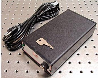
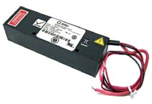
Fig. 10: Commercial helium-neon laser power supplies
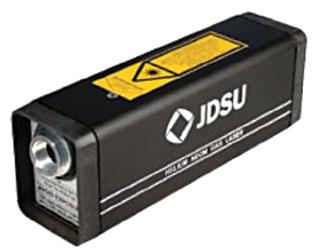
Fig. 11: Helium-neon laser with inbuilt power supply
Fig. 12: Helium-neon power supply for ring laser gyro cavity
voltage to initiate the discharge. Fig. 8 shows a typical circuit. The power supply is configured around an externally driven fly-back type DC-to-DC converter. The ballast resistance is split into two resistances.
Initially, when there is no discharge, the voltage appearing after RSENSE is equal to open circuit voltage. A fraction of this voltage is compared with VREF and the comparator drives the high-voltage trigger circuit configured around SCR, R-C components and trigger transformer. As soon as discharge is struck, voltage appearing after RSENSE drops and the drive pulses are withdrawn from SCR gate. The power supply provides the discharge current through series connection of resistors constituting ballast resistance. In the third circuit topology, the converter circuit is designed to deliver an output power equal to the product of the required sustaining voltage at the power supply output and the discharge current. Since it is a constant-output-power converter, the output voltage would increase without limit in the ideal case in the event of zero current drawn from the power supply. When the output voltage exceeds the required initiating voltage, the plasma current drawn from the power supply forces the output voltage to fall to the sustaining voltage governed by the output power capability of the converter. Compact helium-neon laser power supplies are commercially available both as AC-operated bench-top versions as well as DCoperated supplies for OEM market (Fig. 10). Helium-neon lasers with an integrated power supply are also available (Fig. 11).
Power supplies for ring laser gyroscope sensors
A ring laser gyroscope comprises a helium-neon ring laser cavity with two counter-propagating laser beams. A ring laser gyroscope, which is the heart of the inertial navigation systems of modern aircraft, missiles etc, makes use of a ring helium-neon laser in a closed cavity. Without going into details of its operational principle, it would suffice to mention here that stability of discharge current in each arm of the ring laser cavity is very crucial for proper functioning of the device. Also, it is important to have a stable value of difference between the currents in the two arms.
A power supply configuration that achieves this is shown in Fig. 12. As shown in the figure, there are two current-sense loops controlled by the same reference voltage. Another possible approach could be to use a precision reference for one arm and then use the actual controlled current flowing through that arm as the reference for controlling current in the other arm. The preferred circuit topology for the power supply is an externally-driven PWM-controlled fly-back converter generating a regulated output voltage equal to the sustaining voltage at the required plasma current.
Carbon dioxide laser power supplies
Carbon dioxide (CO2) lasers are operated in both CW and pulsed-output modes. CW lasers are either DCexcited or RF-excited. Pulsed-output lasers are mainly transversely-excited atmospheric-pressure (TEA) lasers. Power supply circuits for DC-excited lasers are similar to the ones described in earlier paragraphs in the case of helium-neon lasers. Different power supply circuits discussed in the case of helium-neon lasers are equally valid for carbon dioxide lasers.
Present-day TEA CO2 lasers use Marx bank capacitor systems. In this system, the arrangement of individual capacitors is such that they are in parallel during the charging process and in series during the discharge opera-
Fig. 13: Marx bank power supply arrangement
Fig. 14: Power supply for RF-excited carbon dioxide laser
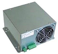
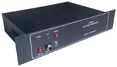
Fig. 15: Carbon dioxide laser power supplies
tion. This means, if each capacitor in the bank were charged to a voltage V, then the total voltage available across the tube for discharge operation would be nV, n being the number of capacitors.
Fig. 13 shows the Marx bank power supply arrangement where the switches are open during the charging. They are triggered simultaneously to the closed position to initiate discharge. Though the Marx bank shown here uses four stages, Marx bank systems with higher number of stages are also used. Marx banks are particularly suitable for producing fast-rising pulses.
Power supply of an RF-excited CO2 laser comprises an RF source and an impedance-matching network (Fig. 14). The RF source may further be split up into an RF oscillator and a cascade arrangement of RF amplifiers, depending upon the output power delivering capability. Frequency of operation is in the range of 50MHz to 150MHz. RF power is fed to the laser cavity through impedancematching network. The laser cavity’s mechanical structure combined with RF discharge can be considered as an electrical load comprising complex impedance. Power transfer efficiency from the RF source to the discharge is a key operational feature of the laser that is made more complicated by the fact that the discharge impedance is power dependent.
CO2 laser power supplies too are commercially available both as benchtop laboratory systems as well as compact versions for OEM market (Fig. 15).
Frequency stabilisation of lasers
Carbon dioxide and helium-neon lasers have Doppler broadened gain versus frequency curves, which is 60MHz in the case of carbon dioxide laser and 1400MHz for helium-neon laser emitting at 632.8nm. With active stabilisation techniques, such as dither stabilisation, optogalvanic stabilisation and stark cell stabilisation, these lasers can be frequency stabilised up to an accuracy of ±1MHz.
Fig. 16 shows block diagram of dither stabilisation scheme. The grating allows selection of various lines within the laser tuning curve. The output of the low-frequency oscillator, when applied to the PZT, moves the grating along the axis and hence varies the output. The other input to the frequency synchronous detector is the error signal, which corresponds to the deviation in the laser output frequency from the line centre.
In fact, the magnitude and phase of the error signal determine the location of operational point with respect to the centre of the Doppler broadened gain curve. While the amplitude decides how far or close to the line centre the operational point is, the phase decides which side of the line centre it is located. Though Dither stabilisation is simple to implement, the disadvantage of this technique is the presence of frequency modulation in the output as a result of laser dithering.
Optogalvanic stabilisation technique is particularly suitable for carbon dioxide lasers. It makes use of variation in discharge impedance due to alteration in internal radiation field intensity. Fig. 17 shows a typical optogalvanic frequency stabilisation set up.
An AC signal is applied to the cavity length transducer resulting in frequency modulation of the laser and therefore modulation of the plasma-tube impedance. The impedance variation, which is proportional to the slope of the output power versus frequency curve of the laser, is measured by exciting the plasma-tube by a high-speed current-regulated power supply and measuring the resulting variation in voltage-drop across the plasma-tube. This voltage is applied
Fig. 16: Dither frequency stabilisation
Fig. 17: Optogalvanic stabilisation schematic
Fig. 18: Stark cell stabilisation block diagram
to the synchronous detector. The other input to the synchronous detector is the reference signal used to modulate the laser cavity length with the help of PZT. The error signal produced at the output of synchronous detector is used to stabilise the laser frequency.
Stark cell stabilisation technique allows dither-free frequency stabilisation. It also allows stabilising frequency anywhere on the Doppler broadened gain versus frequency curve of the lasers. Fig. 18 shows the block diagram of stark cell stabilisation.
A part of the output laser beam is made to pass through the stark cell. An appropriate value of DC voltage is applied to one of the stark plates to make the stark-shifted molecular transition of the gas contained in the cell precisely coincide with the carbon dioxide laser output line of interest. A slowly varying linear voltage ramp may be applied instead. Also superimposed on this is a relatively high-frequency sinusoidal or square waveform. The frequency is 5kHz, typically. The beam at the output of the stark cell is thus modulated in both amplitude and frequency by the applied high-frequency signal around the line of interest.
The laser beam is phase-sensitively detected with high-frequency signal applied to the stark cell as reference. The output of phase-sensitive detector is the frequency-discriminant error signal. The error signal is amplified and then fed back to the PZT through a suitable interface. One of the end elements of the cavity is mounted on the PZT. The error signal adjusts the length of the cavity in the feedback mode to lock the laser frequency to the centre of the Doppler profile of the line of interest.
With this article, the four-part series focussing on the role of electronics in military lasers and optoelectronics is completed. While introduction to role of electronics, solid state laser electronics and semiconductor diode laser electronics were discussed in the earlier parts, important building blocks of electronics used in common gas lasers are discussed in this concluding part. Different circuit topologies in use for design of power supplies for carbon dioxide and helium neon lasers have been discussed at length, highlighting important design-related issues with reference to gas lasers for military applications. Different techniques of frequency stabilisation of gas lasers, which is of paramount importance in applications such as laser radar, have also been covered.

Concluded
Dr Anil Kumar Maini is a senior scientist, currently director of Laser Science and Technology Centre, DRDO, Ministry of Defence, while Nakul Maini is technical editor with Wiley India Pvt Ltd


