8 minute read
Innovation


FidoCaDj: Vector Drawing Software
FidoCADJ is a simple, intuitive application that helps users create vector drawings for schematics as well as printed circuit boards. You can select from a wide range of preset components and print or export your designs to various file formats
Advertisement
Pankaj V.
FidoCADJ is a Java-based multiplatform editor for more than just electronics. It offers a very clean and intuitive environment to help users design their electronics with ease. FidoCADJ is not a simulator, but it offers an agile and effective environment for hobbyists. While there is no netlist concept, it comes with a library that includes electrical symbols and footprints (traditional and SMD) to assist you in your drawings.
FidoCADJ generates electronic circuit outputs with a very compact textual description in various file formats. This makes it very easy to include these drawings in text messages and exchange your sketches in forums and newsgroup discussions.
Some regard FidoCADJ as a Java-based modification of FidoCAD software, which can only be run on Windows. However, it is actually a completely re-written program that offers full compatibility with FidoCAD files, and allows for showing and modifying a file using FidoCAD format. It is not just an adaptation or extension for FidoCAD.
If you are familiar with FidoCAD, getting used to FidoCadJ will not be a problem. In fact, many commands and procedures are quite similar to the original application including some extensions as well.
Compact and efficient
A major advantage of working with FidoCADJ is its simple text format. With no header description required, a simple coordinate system for drawing and various drawing elements, it offers a compact and efficient storage format for the drawings. From the latest version included in this DVD, it uses only the
FIdoCADJ
UTF-8 encoding on all formats.
Unlike other CAD tools and its predecessor FidoCAD, FidoCadJ includes an interpreter that can recognise and correctly interpret any file with or without standard header. Moreover, it can also correctly interpret commands containing text, as long as the number of incorrect lines does not exceed a value set internally in the program (approx. 100). This ensures a fast and efficient functionality, wasting no time, for example, in trying to open a very large binary file.
A simple coordinates system in FidoCADJ identifies a very large area only by whole and positive coordinates. The fixed unit length of in x and y axes at 127μm allows to obtain a good resolution (about 200 dots per inch) for even the smallest SMD packages, without being too fine for everyday use.
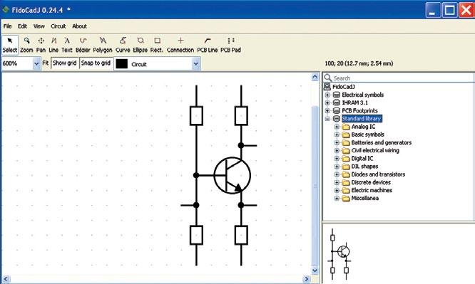
Intuitive environment
FidoCADJ offers graphical flexibility and several intuitive drawing features. In the toolbar situated on the top of the window, you will find the most used and common features for creating and
Advisory note
There are no separate modes of operation for PCB and schematic in FidoCADJ. These appear only at the moment of printing the drawing. Hence it is advised to set the program to resize a schematic according to the size of the page, otherwise the print may have the size of a postage stamp. editing a drawing. Some of the features and functionalities in FidoCADJ, which account for ease of use of this intuitive tool, are discussed below.
The vacuum-tube radios and switches of old times inspire the elements of ease of use in this tool. When you press a button, it remains in that position until another function from the toolbar is selected. So you don’t need to press again and again for the same element in your circuit. Also, you can easily edit or modify the parameters like coordinates or rotation of any drawing element just by double-clicking on it in selection mode.
Intuitive ruler. Drawing a PCB requires measuring distances in the working area. This tool offers an intuitive ruler feature that allows you to easily check any track width, the clearance
between two tracks or the total size of a card. You can just right click and drag to open a ruler in green for your help.
Keyboard shortcuts. From selecting multiple graphic elements to drawing a PCB pad, there are various drawing commands available in FidoCADJ. These allow you to rapidly select various features that let you design faster (as shown in the table), without having to manipulate your mouse.
Flexible graphics. It also offers three different zoom settings for graphical flexibility with the buttons like Fit, Show Grid and Snap to Grid. You can automatically select the most suitable zoom settings in order to show the whole drawing on the screen by pressing Fit button. Show Grid makes it easy to toggle between visible and invisible grids. Finally, the elements added will stick to the nearest step of the grid utilising the Snap to Grid button. (Note: To carefully align various elements, Alt key should be kept pressed while using the other cursor keys.)
Partial customisation of command
bar. FidoCADJ also allows you to partially customise the command bar. In particular, you can either choose to see the icon on each button or both the icon and its text description. These two selectable formats for the icons can be changed from the menu File → Options. Any change in the settings will be applied at the restart of the application.
Easy search and navigation. The libraries include all the standard symbols used in electrical schematics and a wide selection of footprints for drawing PCBs. A quick search text field allows for the quick searching inside the included libraries and the results appear in the form of a tree, allowing you to easily navigate through by typing up and down arrow keys.
Macros. The FidoCADJ application offers you a quick access to all the electrical components, lets you preview them in a dedicated pane, and insert them into the working environment with the help of just a few clicks. The tool includes these electrical components in the form of various macros or symbols in the libraries. A tree list at the right side of the window enables easy
Installing FidoCADJ
Installation file can be found in EFY Plus DVD that came with this magazine. FidoCADJ is a Javabased tool, so Java is a pre-requisite to run this tool on any platform.
The application is distributed as an executable .jar file, which is a Java archive. For many operating systems, you can just double click on the file to run the application, provided that a recent version of Java is installed on the system. The minimum Java version needed to run FidoCadJ is the version1.5, which has been around for a few years now.
But, in some cases it might be useful to run the application from a command line (for example, the terminal in the Unix systems, or the MS-DOS Prompt in Windows). To do so, you can use the following command lines: 1. java -jar fidocadj . Jar 2. java -jar fidocadj . jar ~/ FidoCadJ / test . Fcd (To open a specific file with the application, include it in the command line)
Supported OS: Windows, Linux, MacOS (with Java)
HDD space required: Max 10MB
selection of any preset element in the drawing.
Export with effects. FidoCADJ allows you to export your drawings through several file formats, so you can create simple schematics for use. The generated electronic circuits can be printed or exported to PNG, JPG, SVG, EPS, PGF, PDF, or to a script file format. Also, you can apply anti-aliasing and black-and-white effects to the drawings. To export the current drawing, select File → Export. With Black&White option, you can print any visible layer in solid black.
For the bitmap file formats, it may be useful to enable the option Anti aliasing. While exporting to any vectorial format, it will be beneficial to specify the scaling factor. Anti aliasing reduces the annoying effect of the quantisation that is visible especially on diagonal lines.
Customised libraries. As mentioned above, FidoCADJ includes a collection of libraries of symbols and footprints (traditional and SMD) for assistance in your drawings. It allows you to customise and manage these by defining new symbols and libraries with the luxury of modifying the existing ones. In some specific cases you can also replace the existing libraries with the external ones.
An effective 2D design tool
Summarising, we can regard FidoCAD as an effective tool for designing elec-
Keyboard Shortcuts
Keyboard shortcuts
tronics. Its intuitiveness and handy set of features make it an easy-to-use and learning tool for hobbyists. Moreover, being free, Java-based and multi-platform, it can be of great use.
But it need not be considered uniquely for electronics design as customisation of its libraries can prepare it for any type of 2D drawing and for many other situations, provided those specific libraries can be made available.
FidoCadJ is the official drawing tool of ElectroYou, an Italian social network for electronics. It is a free GPL Licensed software tool that can be downloaded for free at http://fidocadj.sourceforge. net/. You can participate in the forums and blogs related to this tool at http:// sourceforge.net/p/fidocadj/discussion/997486 The author is a technical journalist at EFY
Command Description
A or Spacebar Select For selection of different elements R Rotate To rotate selected elements S Mirror To mirror the selected elements L Line For inserting a line T Text For inserting a test-string B Bezier For drawing a Bezier curve P Polyline For drawing a polyline K Curve For drawing an open or closed natural cubic spline curve E Ellipse For drawing an ellipse G Rectangle For drawing a rectangle C Junction To insert an electrical junction I PCB Track To draw a PCB track Z PCB Pad To draw a PCB pad
Esc Terminate To terminate new insertions


