
MASH
Deployable Emergency Shelter on Mars
Department for Building
Construction and Design – HB2
Vienna University of Technology
Editor
Das Buch kann über die Abteilung Hochbau 2 unter http://www.hb2.tuwien.a c.at/shop/index.php?rr=6 59269
oder bei shop@hb2.tuwien.ac.at erworben werden. Get the book at the Department for Building Construction and Design - HB2 at http://www.hb2.tuwien.a c.at/shop/index.php?rr=6 59269
or mail to shop@hb2.tuwien.a c.at
MASH
Deployable Emergency Shelter on Mars
DESIGN STUDIO 2012/13
Department for Building Construction and Design – HB2
Institute of Architecture and Design
Vienna University of Technology
MASH - Deployable Emergency Shelter on Mars
Published by Vienna University of Technology Institute of Architecture and Design Department for Building Construction and Design – HB2
Prof. Gerhard Steixner http://www.hb2.tuwien.a c.at

Authors and Editors:
Dr. Sandra Häuplik-Meusburger, Dipl. Ing. Polina Petrova
Finishing:
Dr. Sandra Häuplik-Meusburger, Dipl. Ing. Polina Petrova, Dipl. Ing. Laura Hannappel, Dipl. Ing. San-Hwan Lu
Translation: Ing. Gabriela Adam
Original text and projects by the participating students
Copyright: Department, Authors, Students
Photo credits: HB2, unless otherwise indicated
Printing: Vicadruck Vienna
ISBN: 978-3-200-03039-8
Supported by:

The Design Studio
25 students of the Vienna University of Technology worked in groups on different concepts for a deployable and portable emergency shelter for Mars that finally resulted in one common project.
The Studio Approach
Sandra Häuplik-Meusburger & Polina PetrovaIntroduction
Mars surface infrastructure as anticipated for future human missions includes habitation, rover and infrastructure facilities. Exposure of an unprotected human body to the harsh Martian environment, caused for example by malfunction of the space suit or the life support system, can result in serious health damage or even in sudden death.
With regards to potential Extra-Vehicular Activities (EVA) due to science explorations and related safety issues to be performed on Mars, we recommend an additional crew support element. The primary feature of such an element shall be a portable and deployable shelter which can be employed in the event of an emergency that would require immediate action and where return to the base / rover is not possible in due time.
Objective and Design Task
The shelter shall be compactly packed, lightweight and be carried by one astronaut, similar to a “rucksack” or “suitcase” typology. It shall be easy to deploy and accommodate up to two astronauts wearing space suits, e.g. one injured astronaut and one helper astronaut.
It shall temporarily provide a breathable atmosphere for a minimum duration of up to 48h until rescue arrives (rover, other astronaut) or immediate emergency ceases (successful first aid, change of conditions).
Furthermore, deployment of a portable shelter will prolong EVA activities on Mars missions. Astronauts
could possibly stay in the shelter overnight (if required for an experiment for example) or use it to take a short break either planned or due to an unexpected issue.
The Studio
During the 2012 winter term 25 students in the Master of Architecture program developed a series of emergency shelter design concepts.
Based on our design brief for the deployable shelter we assigned the students to three research groups:
(1) Activity-based spatial Analysis: This group analyzed the relationship between the required human activities during emergency situation and potential architectural solutions.
(2) Deployable Structures: Students in this group concentrated on potential structure typologies for the shelter and related materials.
(3) Specific Features: This research includes selected interesting ideas and partial solutions for potential challenges of the specific environment.
At the same time, students developed their ideas into initial concepts. Following extensive reviews by the project team and our external experts the most promising concepts were chosen for further development and the first big-scale-models were built.
In total three prototypes were developed and tested. The second prototype was tested with the suit tester during the Dress Rehearsal Meeting in Innsbruck. The
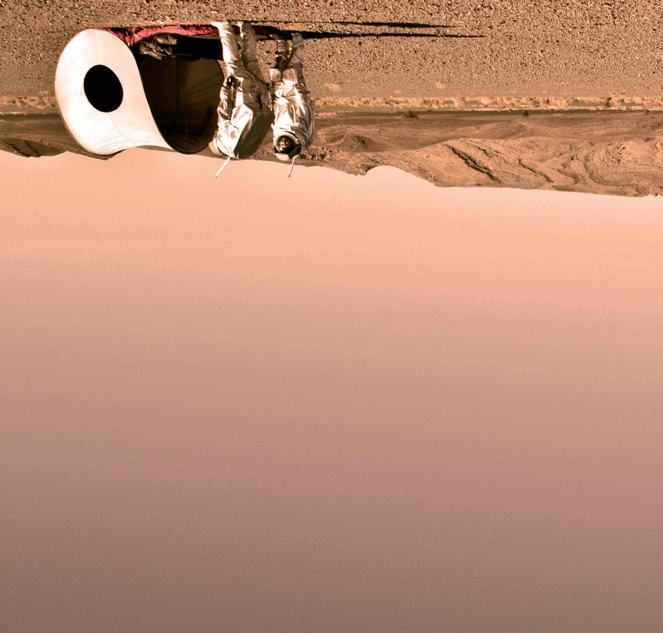
final prototype was transported to Morocco to be tested within the OEWF Mars Analog Field Simulation between 01. - 28. February 2013.
Along the design process, we have evaluated the shelter concept concerning its usability, functionality and adaptability.
The structure of the booklet follows the work process.
Further information:
MARS - NASA explores the red planet http://www.nasa.gov/Mars
Morocco Mars Analog Simulation http://www.oewf.org
Department Hochbau 2 Publications http://www.hb2.tuwien.ac.at/shop
Project Team
Vienna UT
Project Lead
Dr.-Ing. Sandra Häuplik-Meusburger

INSTRUCTOR
Ass.Prof. Department HB2
Expertise: Architecture and Habitability in extreme environment, adaptable and flexible habitation design
Extended Team
Medical Consulta nts:
Dr. Simon N. Evetts , Wyle GmbH, Medical Projects and Technology Unit Lead, Crew Medical Support Office, European Astronaut Centre; Dr. Chan Sivanesan , Intern, Crew Medical Support Office (HSO-UM), European Astronaut Centre (EAC)
Consultant for Prototyping: DI Michael Schultes
DI Irmgard Derschmidt
DI. Polina Petrova

INSTRUCTOR
Ass.Prof. Department HB2
Expertise: deployable space frames and freeform deployable structures
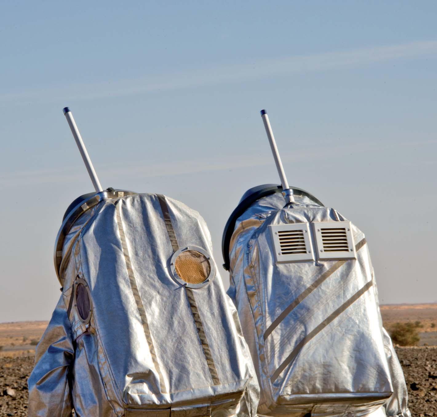
Consultants for the AOUDA space suit: Dr. Gernot Grömer, OEWF; Daniel Föger, Analog astronaut, OEWF, Physics Student
Simonauts TU-Student team: Zuzana Kerekretyova , Nikolaus Gutscher and Kristoffer Stefan
DI. San-Hwan Lu

INSTRUCTOR
Ass.Prof. Department HB2
Expertise: building technology and design, complex builiding envelope geometries
OEWF Analog Astronauts: Christoph Gautsch , Gernot Grömer and Daniel Schildhammer


Research
Based on the preliminary design brief for the deployable shelter students worked in groups on relevant research topics.
Activity-based spatial Analysis Research
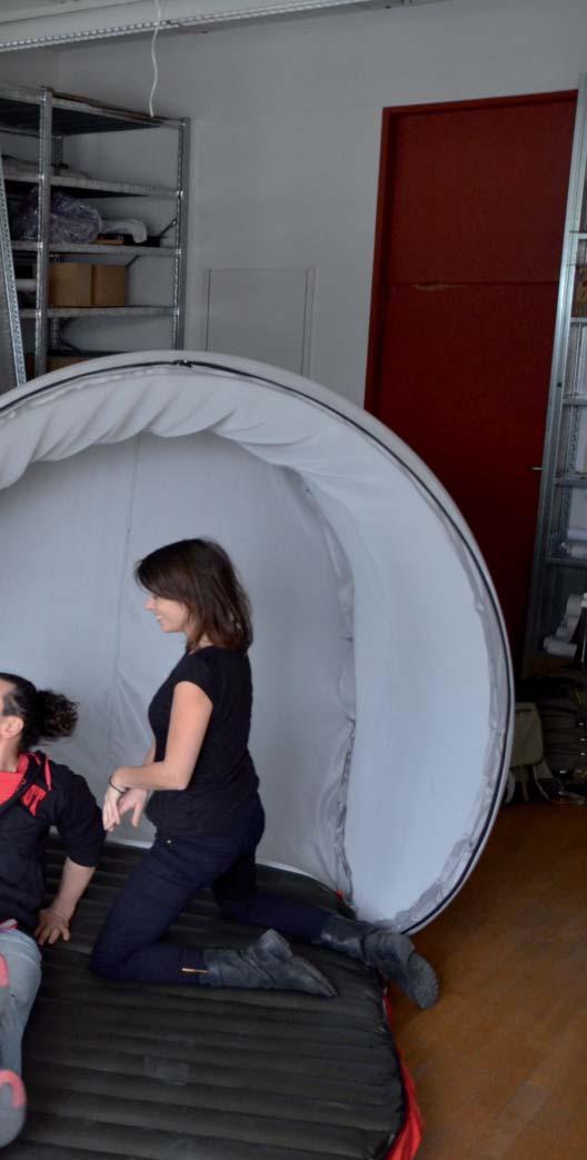
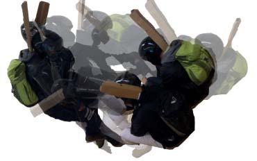
The students analyzed the spatial requirements for two astronauts based on spatial maneuverability, human activities and interaction. The aim was to define the minimal space envelope necessary for the emergency shelter. This requires the specification of typical emergency scenarios which can be expected during ExtraVehicular Activities (EVA) on Mars.
Combinations of different emergency situations were analyzed regarding spatial requirements for the recovery (rescue) activities and the feasibility of these scenarios. This is strongly related to other design criteria like the maximum size and weight possible to be carried by one astronaut.
reach radius: standing
MUST - SHOULD - COULD
reach radius: sitting
reach radius: relaxed sitting
2D and 3D diagrams, analog simulations performed by the students as well as some inputs from the Aouda Spacesuit-Tester were carried out and analyzed during this research. The evaluation then served as a basis for the definition of possible scenarios using the shelter and for roughly determining shelter size.


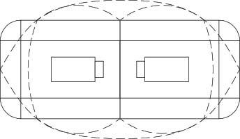
Evaluation
Combination 1: all configurations
Combination 2: all configurations without transport
Combination 3: all configurations without transport without lying on „bed“
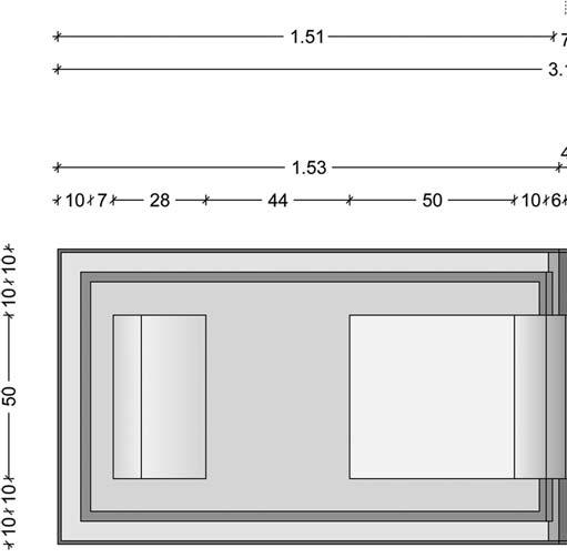
floorplan
Combination 4: without transport without lying on „bed“ without removing suite
floorplan
floorplan
Combination 5: only sitting and crouching
Combination 6: only sitting
floorplan
floorplan
floorplan
Deployable Structures Research
An important feature of the emergency shelter is its compactly packed lightweight structure that allows it to be carried by one astronaut, similar to a “rucksack” or “suitcase” typology. On the other hand it should accommodate up to two astronauts (with space suits) when deployed by expanding to five times its initial size. In case of an emergency requiring immediate action it should be fast and easy to deploy by the uninjured astronaut.
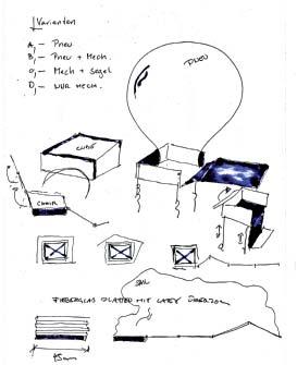
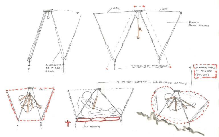
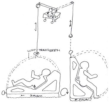
These special features implicate a wide range of challenges and require an analytical study of different typologies of deployable structures. The students analyzed different deployable systems like pneumatic systems, deployable bar and surface structures, hanging films and bells. Basic kinematic concepts were worked out and specific case studies were simulated. All systems were evaluated in regards to design criteria like weight, stability, handling and reusability. The research which was carried out brought critical reflections to light and furthermore serves as a basis for future experiments with the ideas and techniques that were revealed.
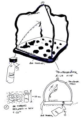
Specific Features Research
In addition to the study of deployable structures, capable of only changing size and volume, some other features of the shelter like functional and topographical adaptability were explored by another group of stude nts. In this research the topic of Mars topography and the required design features to withstand this surface were tested. In comparison to known earth surface typologies, the Mars surface most closely resembles Earth’s rocky surfaces. Therefore the shelter should have adaptable parts at the bottom, e.g. telescopic feet. In this manner, the
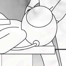
adjustment to the surface does not have to be all at once. By adjusting the telescopic elements leveling could be achieved on uneven surfaces. Another possible solution could be pneumatic elements in the form of spheres or tubes on the bottom of the shelter. These would be separately inflatable, thus enabling height adjustments in relation to the uneven terrain surface. To increase stability, adjustable pneumatic “thorns” can be added to the underside of the membrane to stabilize the shelter on the uneven Mars surface.
Another important topic was the adaptability of the shelter in regard to functional requireme nts. Students also focused their research on the adaptability of the structure through changing its shape, which allows manifold different human activities to take place within its confines without increasing the volume of the structure. Different mechanical devices to control the shape of the structure consisting of either rigid foldable frame eleme nts, pneumatic muscles or cables, were tested and evaluated with focus on usability and simplicity.
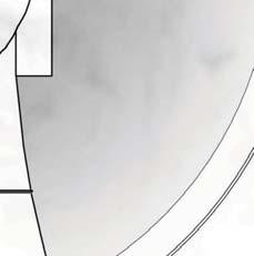
point support / pads

linear support / hoses
Functional adaptability

Workshop Austrian Space Forum
29th - 30th October, Innsbruck
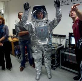
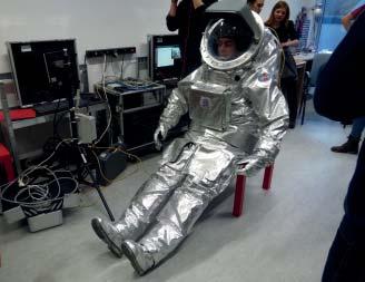
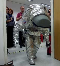
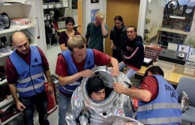
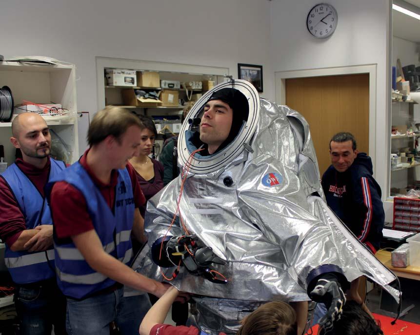
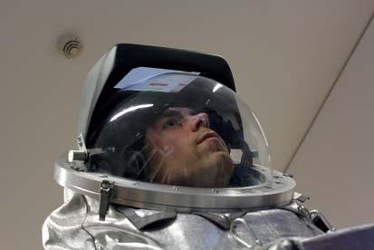
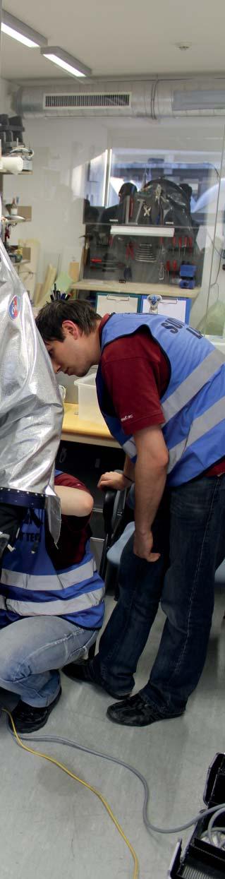
The team visited the OEWF office in Innsbruck (Austrian Space Forum) to get relevant technical and user-related information about their analog spacesuit AOUDA to incorporate that into the shelter´s design process.
Day 1: Dr. Gernot Grömer, OEWF’s chairman, gave a presentation on Mars’ atmosphere and avail able materials and machines. At AOUDA spacesuit lab, a demonstration on how the spacesuit is put on was given. All of the students were able to try on gloves and do exercises, such as tying shoelaces or operating walkie-talkies.

Day 2: The group did role playing to better understand the astronauts’ needs on Mars and what different alterations of the design would mean to the users. Furthermore, equipment such as a mini rover was demon strated. The group got to try everything themselves, to once again see things from the analog astronauts’ perspective.


Design Concepts
Several concepts were developed by the students in multiple design stages. The further progress of the design project Mars and its prototypes is on the basis of the concept „res[C]ue me“ (page 51) .
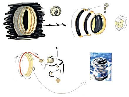
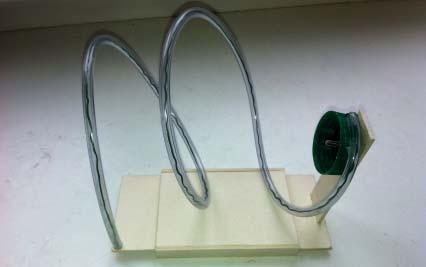
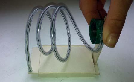
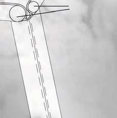
Deployment of the Spiral

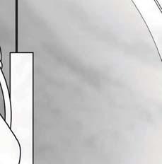
Adaption of the Shelter
Spiral System
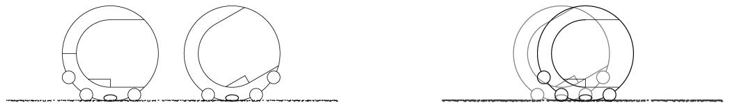
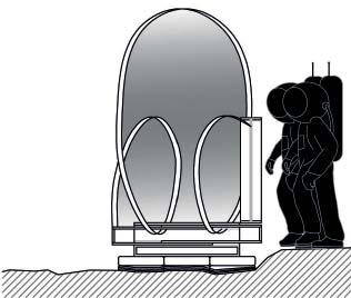
As an inspiration for the emergency shelter design we took the spiral. It is a flexible form that can easily change its size in both directions. Both length and height depend on the required form.
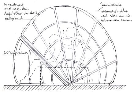
We studied the behavior of a spiral under the infl uence of various forces and developed the following concept: The shelter´s deployability, collapsibility and flexibility is based on simple screwing and stretching of the spiral, which serves as the main structural element. It is a pneumatic tube made of airtight silnylon fabric. Depending on the air pressure inside this tube, the spiral´s density as well as shelter size can be controlled.
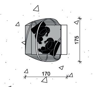
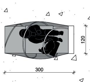
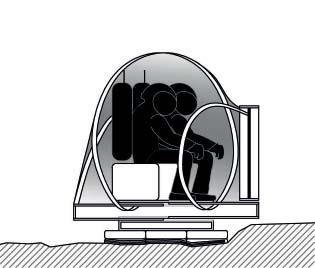
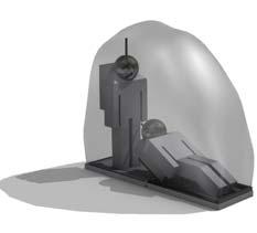
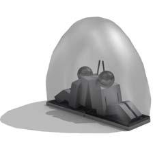
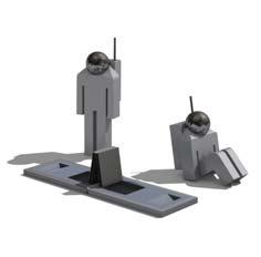
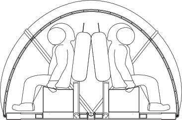
State 1: The state with the biggest height and the smallest length - both astronauts can stand inside the shelter
State 2: A state between 1 and 3 - both astronauts are able to sit in the shelter
State 3: The state with the largest length - the astronauts are able to lie and kneel
The skin of the shelter is made out of multilayered stretchy fabric. It consists of an airtight inner membrane (Silnylon) and a midlayer - a strong fabric woven from Panox and Vectra fibers. On the outside the skin is coated with aluminum that protects the shelter from radiation.
The skin is flexibly connected to the spiral and can move around it. This movement is provided by stripes (made from the same material as the inner membrane) welded onto the inner side of the skin pulling over the spiral. The biggest advantage is that the size of the emergency shelter can be adjusted even when astronauts are already inside.

 Zuzana Kerekrétyová, Rene Mathe, Markus Mitrovits


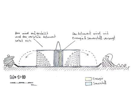
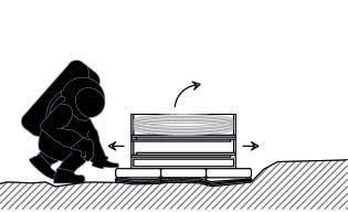
Emergency Case
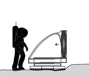
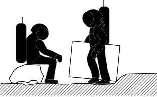
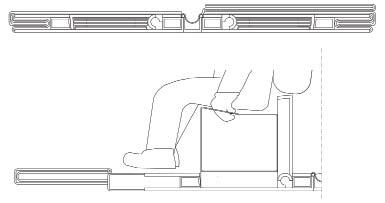
An important task during the development of the “Emergency Case” was to cover all possible scenarios. First priority was energy and oxygen support as well as stable positioning of the astronaut. Another necessary part of the development was an airproof shell, which could be inflated in case of emergency to provide atmospheric pressure and enough space to give first aid.
The deployment of the “Emergency Case” is conceived in a way that could fulfill the different requirements depending on their priority. To provide the most important functions - supply and positioning - the case only has to be opened. The shell can be closed to protect from radiation. In case of a damaged spacesuit or heavy injuries the shell can be inflated with 0,6 bar to guarantee survival.
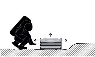
The “Emergency Case” can easily be carried by one astronaut. It is made out of a solid, scratch resistant material since the outer part serves as the base for the shelter.
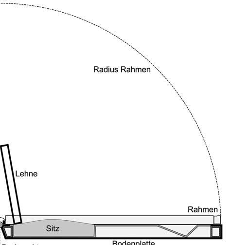
When the case is opened, the surface measures 310 x 90cm. It is only 10cm high to easily place an injured astronaut on top of it. Two back rests with integrated oxygen and energy supply can be pulled out.
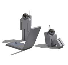


The frame is assembled on the same axis as the bottom plates. It folds and pulls the cover over the astronauts. This shell can be inflated so the astronauts have the ability to move.
Nikolas Karhan, Markus Scherz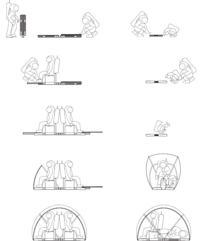
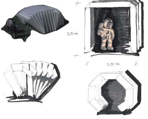
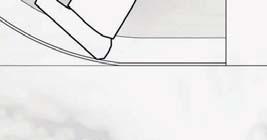
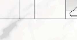
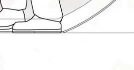
Deployable Stretch Shelter
In the folded state, the shelter resembles a portable suitcase. Opening the case deploys a solid surface panel (made of carbon composite or Kefl ar-fabric and silicone, protected by open-weave textile Nextel). The pneu is located between the inner and the exterior carbon shell.
The process of folding the pneumatic floor and exterior-wall elements is facilitated by the Mars atmosphere. Floor and walls are separately inflatable. Thus, the floor can be first used as a „scoop-stretcher“ and later on as a shelter. The expandable floor allows the astronauts to carry out a number of complex tasks. The shelter can be adjusted in height, so that both astronauts can stand. Other possible positions include lying back to back or one astronaut lying with the second one sitting next to him.
The backrest (place for the backpack while sitting) is popped out of the bottom plate and locks in the upright position. After it locks, the seat cushion is deployed, which allows for a seating-area of 30x40cm.
 Öhreneder
elements


 Nikolaus Gutscher, Josef Öhreneder


