
19 minute read
Hydraulic Cylinder Cushions Fight Mechanical Shock Sudden stops add stress to a machine and its cylinders


Every day, hydraulic cylinders work to push, pull, tilt, raise, and hold loads on diverse equipment. Often the operator is responsible for gradually stopping the cylinder in a controlled manner. However, in some applications, the cylinder may fully extend or retract and reach the end of the mechanical stroke, but it is not stopped by the operator. This likely is not a problem if the speed is slow. If there is a high-inertia load, when the cylinder reaches the end of stroke the sudden stop can cause mechanical shock, with effects ranging from mild annoyance to serious risk.
HYDRAULIC CYLINDER CUSHIONS
FIGHT MECHANICAL SHOCK By Tony Casassa, Application Engineer, Aggressive Hydraulics
Inertia is a product of mass and speed. Consider a hydraulic cylinder pushing or pulling a wheeled cart horizontally. When the cylinder moves slowly and reaches end of stroke, the change of speed is small and does not cause any problems. If the hydraulic flow increases and the cart moves at a higher velocity, the inertia increases, and the resulting potential shock at the end of stroke also increases. Because the cart has wheels and is moving horizontally, increasing the mass of the cart will cause only a small increase in the pressure required to move the cart, but it will cause a larger increase in the inertia.
Now imagine the cylinder moving the cart up an incline. The pressure required to move the load is higher. When the cylinder reaches the end of stroke, the pressure still increases to the system maximum, but the increase is smaller; therefore, the shock is A strong shock at the end of cylinder stroke can damage machine components, negatively affect machine performance, or present a risk to the machine operator.
less. On the other hand, if the cylinder moves the cart down an incline, the inertia will increase, and the shock will be higher.
Another example is a hydraulic cylinder opening and closing a swinging gate around a pivot point. Typically, the cylinder is mounted near the pivot point and provides a relatively high force and short stroke. Due to mechanical advantage, every inch of cylinder travel multiplies into a longer distance for the gate's edge.
The wider the gate, the further the edge is from the pivot point, and therefore the higher the rotational inertia of the gate.
A strong shock at the end of cylinder stroke can damage machine components, negatively affect machine performance, or present a risk to the machine operator. When the load moved by a cylinder comes to a sudden stop, stress is applied to the cylinder and the machine's mechanical structure. Excessive stress on these structural components and pressure spikes in hydraulic tubes or hoses can cause premature failure. Shock can also degrade machine productivity. For example, if a cylinder is moving a load of aggregate material, it may cause some of the material to fall out of the bucket or container. Of highest importance is the potential risk to the

operator. For example, the operator in an aerial work platform requires the cylinder to come to a slow, controlled stop.
Historically, the responsibility would be on the operator to slow and stop the cylinder to prevent any undesirable shock. Now there is increasing market demand for user-friendly machines, and industry and safety regulations place more responsibility on the machine designer.
In some cases, the best solution is the addition of switches or sensors to detect cylinder position, a proportional hydraulic valve to control the flow, and a programmable logic controller to read the input and determine
the output. However, due to cost, serviceability, or operating environment, the electronic solution may not be suitable.
END-OF-STROKE CUSHIONS
Hydraulic cylinders with end- of-stroke cushion features have been available for many years, with the most familiar being spear-type cushions, which are common in tie rod construction cylinders but also used on welded construction cylinders.
Spear-type cushions.
Spear-type cushions can be nonadjustable, but more often they’re adjustable. This type of cushion can be effective, but it also has some shortcomings to consider. Because the design has a spear or sleeve that enters and exits a concentric pocket, if the difference between the spear and pocket diameter is too small, there is a risk of metalto-metal contact and galling. On the other hand, if the clearance is too large, the effective orifice will be too large, and the cushion will be ineffective.
A downside from the design standpoint is that the cushioned flow has two parallel paths. Oil flows through the annular area created by the spear and pocket as well as across the fixed orifice or adjustable needle valve, resulting in a complex scenario for predicting the flow. The spear-type design requires space in the head and end cap for the cushion-adjusting needle valve and the check valve for incoming flow. Lastly, although the ability to adjust the cushion may have advantages in some circumstances, it also allows the possibility of incorrect adjustment; for example, an operator seeking to improve productivity without understanding the potential negative consequences. Cushion piston. The cushion piston is an alternate solution to provide the cushion function and offers advantages over the spear-type cushion. This solution can be designed for a wide range of flows and can be more effective in a lower flow range than the spear type. The controlled flow
Figure 1: A. Cast-iron piston ring, B. Axial holes, C. Cross-drilled hole

Figure 2

Figure 3

Illustrations: Aggressive Hydraulics
passes through a single orifice, which allows more predictable cushion performance. The orifice and the check valve function are built into the piston, requiring no further space increase than the length of the cushion zone, keeping the cylinder compact in size. It is nonadjustable, which prevents the possibility of malfunctions caused by improper adjustments.
As the name suggests, the features that provide the cushion effect are built into the piston. On the outside diameter of the piston, in addition to the typical bidirectional elastomeric piston seal, a cast-iron piston ring is added in each direction the cushion is desired, either on the blind end for a cushion at full retract, on the rod end for a cushion at full extend, or both as shown in figure 1.
The groove for the cast-iron piston ring is wider than normal, allowing it to shift slightly in the groove. In addition, on each end of the piston there is a series of axial holes and a single cross-drilled hole.
These features do not affect the cylinder operation during most of the stroke. Flow can freely enter and exit the cylinder, and the elastomeric piston seal prevents internal leakage. The cast-iron ring can “float” in the wide groove, and the pressure is the same on both sides of the ring. When the cast-iron ring passes the port, the exiting flow is forced through the axial and cross-drilled holes, creating a pressure drop. With higher pressure on one side, the ring is forced to the opposite side of the groove, and flow must pass through the single cross-drilled hole.
If properly sized, the orifice controls the flow rate of oil exiting the cylinder. The pressure of the incoming fluid increases until it reaches the maximum level, as determined by the setting of a component outside the cylinder, commonly a relief valve or a controller on a variable displacement pump. The relief valve must open to divert the flow that cannot enter the cylinder, or the pump displacement must decrease to reduce the flow (figure 2).
Although the cushion may be desirable to slow the cylinder at the end of stroke, when the direction is reversed it is preferred for it to operate immediately at a normal speed. This is the reason the groove for the cast-iron ring is wider than normal. Just as the pressure drop of the exiting flow moved the cast-iron ring to one side of the groove, now the pressure drop of the entering flow moves it to the opposite side. The flow can now pass under the cast-iron ring and out the axial holes with minimal or no restriction. This feature is referred to as fast start-up. After the cast-iron ring passes the port, fluid flows directly into the cylinder, and once again, the cushion features do not affect performance until the next time it reaches the end of stroke (figure 3). (Continued on page 24)
Figure 4

Illustration: Aggressive Hydraulics
(Continued from page 23)
When working with cylinders with any cushion, it is vital to consider the possibility of pressure intensification. To reduce the cylinder speed, the exiting flow must be restricted so that the incoming flow reaches the maximum pressure. However, because of the area difference on each side of the piston, the exiting flow will not be the same pressure as the incoming flow. On the extend side, also known as the blind or cap end, the fluid under pressure acts on the full bore diameter of the cylinder. On the retract or rod side, the fluid under pressure does not act on the center area because of the rod; it only acts on the annular area between the rod and the bore. The ratio of the extend area to the retract area is known as the cylinder ratio. The cylinder ratio is typically in the range of 2:1 to 3:1, but if the rod is large relative to the bore, it can be as high as 10:1 (figure 4).
If the pressure is controlled by a main system relief set at 3,000 psi (207 bar) and the cylinder has a ratio of 2:1, when the cylinder is retracting and the cushion is active, the rod side pressure increases to 3,000 psi (207 bar). Because the extend side area is greater by a factor of two, the resulting pressure on the extend side is calculated by dividing by two, or 1,500 psi (103 bar).
This pressure is used to design the control orifice size in the piston for the designed flow rate. If the same cylinder has a cushion at full extend and the extend side pressure increases to 3,000 psi (207 bar), the resulting pressure on the rod side is 6,000 psi (414 bar). This higher pressure is completely contained within the cylinder and is not measured with a cylinder port gauge, nor can it be prevented or limited with the addition of an external relief valve.
Air Compressors Clean Dry Air Improves Performance...
Clean, Dry Compressed Air Starts with The Extractor/Dryer® Manufactured by LA-MAn Corporation


• Point of Use Compressed Air Filter to
Improve and Extend Equipment Life • Removes Moisture and Contaminates to a 5-Micron Rating: Lower Micron
Ratings are Available • Models with Flow Ranges of 15 SCFM to 500 SCFM Rated UpTo 250psi are
Standard • Differential Pressure Gauge Built in • Mounting Hardware Included for
Easy Installation • Weep Drain is Standard; Float Drain or Electronic Drain Valves Optional
In addition to using this pressure to determine the orifice diameter, this higher pressure must also be considered when selecting seals, tube-wall thickness, and head retention methods to prevent cylinder failure. If the cylinder has a relatively large diameter rod and therefore a high cylinder ratio, even at low system pressures it may not be economically feasible to design the cylinder for the resulting rod-side pressure. It may be necessary to add a relief valve set at a lower pressure specifically for the extend side of the cylinder. If that does not provide adequate extend force, the cylinder may not be a good candidate for a cushion at full extend, and deceleration should be accomplished by a different method.
Although removing the potential for incorrect adjustment may be a benefit in some applications, in others the benefits of adjustment outweigh the risk. For these applications, it is possible to adapt the cushion piston design to accommodate an adjustment valve in the end cap or head gland.
As with all hydraulic components, the introduction of a control orifice makes it more sensitive to contamination. A small partiHydraulic cle can lodge in cylinders with the orifice and end-of-stroke block or restrict cushion features flow, negatively have been affecting cushavailable for ion performance. It is important many years, with for proper operthe most familiar ation and long being spear-type life to maintain a cushions. high level of fluid cleanliness via proper filtration. A race car on a track can stop one of two ways. If the driver applies the brakes, the reduction in speed is controlled and gradual as the brakes convert the energy to heat and the heat is dissipated. If the car hits the wall, the change in speed is abrupt and violent. The car will likely sustain mechanical damage as it absorbs the change in energy. A welded cylinder with a properly designed cushion piston is analogous to properly applied brakes, as the energy is transferred to hydraulic heat and the cylinder stops in a controlled manner. This can provide a significant benefit to the machine and the user.
HITACHI FLANGELOCKTM
PRODUCT AND CAP KITS AVAILABLE Part number Part description Applicable machines SPOTLIGHT SWINGFLGLCK2062 SWINGCAP2062 Swing hose FlangeLockTM kit Swing circuit cap kit EX3600, EX5600, EX8000 EX3600, EX5600, EX8000


Number of parts
16 x 2062U - red FlangeLockTM
16 x 2062 - cap
TRAVELFLGLCK2462 Travel hose FlangeLockTM kit EX3600, EX5600, EX8000 16 x 2462U - purple FlangeLockTM
TRAVELCAP2462 Solid ModelsTravel circuit cap kit EX3600, EX5600, EX8000 16 x 2462 - cap Adaconn®+ Inserta® continue to add to their growing website library of STEP and 3D pdf files.FRONTATTFLGLCK326162 Front attachment FlangeLockTM kit EX3600, EX5600, EX8000 14 x 3262U - black FlangeLockTM 4 x 3261U - black & silver FlangeLockTM
STEP files are now available for ICT Thread-in Check Valves, ICS Slip-in Check Valves, ICFT, ICFS, and FRONTATTCAP326162 Front attachment cap kit EX3600, EX5600, EX8000 14 x 3262 - cap 4 x 3261 - cap Filtration Solutions for ICF Check Valve Flange Bodies, IGSP and ICVR BOOMARCHFLGLCK3262 Boom arch hose FlangeLockTM kit EX3600, EX5600, EX8000 20 x 3262U - black FlangeLockTM Low-Flow Applications Check Valve Retainers, IBF and IBFP Ball Valves, BOOMARCHCAP3262 Boom arch hose cap kit EX3600, EX5600, EX8000 20 x 3262 - cap Anodized aluminum housings with ico OptimizerTM Pressure Control Valves, IFRA

all stainless steel filter elements for Rotational Adapters, IFRC Rotational Connectors, CONTAMINATION CONTROL flow rates up to 15 gpm and 3000 psi. Unified Modular Fittings, Specialty Plates, and Routine and scheduled maintenance of hydraulic systems are vital to getting the most out of your Hitachi Mining Excavator. While Pipe sizes ranging from ¼” to 1” npt and SAE straight threads, too. You Adaconn® AFO and AFP Flange Adapters. These solid models make it easier to incorporate maintenance plays the largest role in the prevention of unnecessary machine downtime, it can also expose the hydraulic system to high levels of contamination rapidly decreasing component longevity. The importance of contamination control is sometimes overlooked when performing maintenance due to incorrect practices being used. choose your level of filtration from 5 to 595 microns. Positive o-ring seal and Adaconn®+ Inserta® components into smartly designed hydraulic systems in order to save space, THE FLANGELOCK™ TOOL AND CIRCUIT BLANKING CAPS The FlangeLock™ tool and caps are the ultimate contamination control tools for protecting your hydraulic system. The FlangeLock cleanable element. In stock. time and money, eliminate piping leaks, and add value. allows for the simple sealing of open hydraulic flanges without tools while the caps can be bolted in place of a flange connection. Flow Ezy Filters, Inc. Phone: 800-237-1165 Solid models may be found under the ‘Tech Resources’ tab of the website. Easy on, easy off, they offer a leak-proof solution to hydraulic systems and environmental cleanliness. FlangeLock stop the mess. HITACHI MAKING CONTAMINATION CONTROL EASY ™ tools and caps Fax: 800-252-1730 Email: flowezy@flowezyfilters.com Website: www.flowezyfilters.com ADACONN®+ INSERTA® Blue Bell, PA • www.inserta.com Hitachi have packaged FlangeLock™ tool and caps specifically for Hitachi mining excavators. The Hitachi customised kits make sure no matter which component routine maintenance is being performed on, you will always have the exact number of FlangeLocks™* and caps to help reduce contamination. *Note: FlangeLocks™ are not to be used under pressure
Liquid Level Switches Liquid Level Switches are designed to shut down machinery or turn on warning devices when liquid supply recedes to a predetermined level. They can be wired to flash warning lights, sound howlers, shut down machines, or signal computers. This is especially helpful in unattended automated plants. Available with a housing for external mounting or without housing for internal applications.

Oil-Rite Corporation PO Box 1207 Manitwoc WI 54221-1207 Phone: (920) 682-6173 Email: sales@oilrite.com www.oilrite.com Call you local Hitachi Muswellbrook representative or the branch on 02 6541 6300 for more information. • No tools required • No expensive hardware needed • No more rags stuffed into hoses • No more messy plastic caps • The ultimate contamination control tool • One hand installation • Eliminate hydraulic oil spills & clean up • Quick installation & ease of usage Stop The Mess! SAVE TIME SAVE MONEY SAVE LABOR SAVE OIL • Safe for personnel & environment • Industry acclaimed


For more information, call 203-861-9400 or email sales@flangelock.com. www.flangelock.com

Vac Cubes Multi Venturi Vacuum Pumps With over 30 years of proven results Vac Cubes and our multi stage venturi vacuum pumps are a great fit for your vacuum application. They are designed to provide higher vacuum flows with less air consumption. Multiple models available with maximum vacuum up to 27”hg and vacuum flows up to 25CFM and the ability to manifold together.
Introducing—9S Series Investment Cast Swivels The "9S" Series swivels represent one of the most complete range of sizes and configurations available to industry. This series has been redesigned to incorporate a one-piece barrel arrangement, thus eliminating the need for braze joints. These swivels are pressure balanced with operating pressures up to 5,000 psi. All configurations are designed with a 4:1 Safety Factor and include RoHS compliant zinc plating.
P.O. Box 6479 • Fort Worth, TX 76115 V. 817/923-1965 • www.hydraulicsinc.com

info@vac-cube.com 727.944.3337 www.vac-cube.com


Protection for All Things Hydraulic, Pneumatic and Fluid Power MOCAP manufactures an extensive range of protective closures to guard pipes, hoses, and hydraulic fittings from dirt, moisture, and damage to help maintain equipment reliability. Included are a variety of sizes and styles of Threaded and Non-Threaded plastic Caps and Plugs for Metric, NPT, BSP, JIC and SAE Threaded Connections, Ports and Fittings. These are in addition to MOCAP’s already extensive lines of low-cost Caps, Plugs, Grips, Netting, Tubing and Tapes for general Product Protection, Finishing and Masking. All of our stocked items are ready for immediate shipment and available in Box, Mini-Pack and Micro-Pack quantities. Free Samples are always available for testing purposes.
sales@mocap.com www.mocap.com

Now Available! Full MTRs and Lot Traceability MAIN Manufacturing Products, Inc. now offers full MTRs and lot traceability on all common flanges. Carbon, stainless, and coppernickel alloy are available. If not part of our 7000+ in-stock products, MAIN can manufacture and ship quickly. 4-5 days is common from our US facility.
MAIN Manufacturing Products, Inc. Phone: 800.521.7918 • E-mail: info@mainmfg.com
Proportional Directional Flow Control Valve PWK10 Series
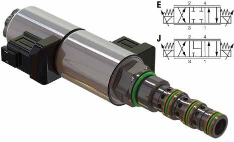
Screw-in cartridge, solenoid operated, 4-way, 3-position, direct acting spool • 350 bar, 36 L/min • Available in closed and motor spools • 1000 hours salt fog rust protected • 28W, IP69K ingress protected • Repeatability / Linearity within 3% HYDAC Technology Corporation – Hydraulic Division 630.545.0800 www.HYDAC-NA.com
Stainless Steel Check Valves, Thread-in Type

INSERTA® IGT (Stainless Steel) Guided Disc Thread-in Type Check Valves can be inserted in manifolds, subplates, flanges, and integrated valve systems for use up to 6000 psi. Their compact geometry allows for flexible design options. The patented guided disc design provides superior resistance to wear in conditions prone to significant turbulence, high flow transients, or high cycling. Valve discs and seats are hardened and flat lapped for positive fluid shut off. The valve disc may be provided with a customer specified orifice to provide fixed orifice flow control function in the checked direction. Thread sizes from 7/16-20 to 1-5/16-12 typically ship from stock.
INSERTA® PRODUCTS BLUE BELL, PENNSYLVANIA, USA www.inserta.com

Go ahead. Push me. Ordinary heavy duty not heavy enough?
Heavy-Duty Mill Cylinders for:
• Induction-Hardened, Chrome-Plated Rods • Heavy Wall Tubing • Replaceable Glands & Retainer Rings • High-Load Piston Design
Think indestructible and call Yates. www.yatesind.com
Yates Industries (HQ) 586.778.7680
Yates Cylinders Alabama 256.351.8081
Yates Cylinders Georgia 678.355.2240
Yates Cylinders Ohio 513.217.6777
Contact us to showcase your products and services in the Product Spotlight. This special section is a high-profile area offering productspecific advertising.
Visit fluidpowerjournal.com for more information or to view our media guide.


PRODUCT REVIEW
New Switches and Sensors from Norstat
»NORSTAT INC. RECENTLY introduced two new products that add to its lines of safety switches and vacuum and pressure sensors.
The new S-type, master coded, RFID safety switch for high-risk safety applications is electronically operated. As a stand-alone safety switch, it is designed to work with any safety relay. The S-type switch uses a unique, frequency operated, switching system ensuring that only an S-type actuator can be used to complete the switch-stopping operation, thereby preventing any unauthorized attempt at overriding the switch. The electronic design provides precision switching and on-switch indication for reliable operation. For high-risk applications, the switches offer excellent protection against manipulation, interference, or tampering.
Norstat’s line of vacuum and pressure sensors now has a new IO-Link interface. IO-Link is a manufacturer-independent, globally standardized, bidirectional, digital point-to-point interface through which a controller can easily communicate with sensors and actuators. Using extensive data, industrial processes can be monitored and controlled in detail and in real time. An intelligent interface such as IO-Link is essential in collecting data and allowing flexibility and control during production. The IO-Link can be easily integrated into existing systems, as it requires no special demands on wiring or mounting and runs via unshielded cables and standard industrial connectors.


