

Industrial Ethernet Book
The only publication worldwide dedicated to Industrial Networking and the IIoT. Visit iebmedia.com for latest updates.
New website offers deepest, richest archive of Industrial Ethernet and IIoT content on the web.


View and/or download latest issue of Industrial Ethernet Book and past issues. Search our database for in-depth technical articles on industrial networking. Learn what's trending from 5G and TSN, to Single Pair Ethernet and more. Keep up-to-date with new product introductions and industry news.


Focus on Industrial Wireless
In this issue of the Industrial Ethernet Book, we are offering our 2022 Special Report on Industrial Wireless technology trends and applications.
Beginning on page 7, six industry experts provide their perspective on the trends and technology in Industrial Wireless applications. From Industrial 5G to Wi-Fi 6, technology and speed advances along with the need for more flexible networking to meet the needs of IIoT applications is driving innovations in industrial wireless communication.
According to Jürgen Weczerek, Manager Product Marketing Wireless and Security at Phoenix Contact, “5G and Wi-Fi 6 are expanding the application possibilities for industrial wireless in the smart factory. These are clearly the latest generations of wireless technologies: for cellular communication it is 5G and for WLAN it is Wi-Fi 6 (IEEE 802.11AX). In the future, both have the potential to be a game changer for the broad use of wireless communication in the smart factory."
The potential of these technologies is yet another example of how Industrial Ethernet and factory networking technologies are at the forefront of technology innovations in the smart factory.

You might also want to check out the technical article, "Industrial 5G implementations get closer every day" starting on page 14.
5G not only is offering promising performance enhancements for consumer applications, with up to 20x more throughput than 4G and up to 100x more users in a single cell. But industrial applications will benefit far more from the boost in 5G performance, even though industrial applications have a different set of network requirements.
On page 16, we offer coverage of issues related to addressing reliability in industrial wireless networks. Industrial wireless technologies are indeed required to enable autonomous and remote-controlled robots and vehicles, to improves collaboration between mobile workers and increase the overall efficiency and safety of an industrial system. Reliability is a key issue for all of these applications.
We finish up our coverage of industrial wireless with two key articles. Check out "60 GHz wireless data interconnect for slip rings" beginning on page 18 and "Industrial wireless connectors and the factory of the future" on page 23.
Experts agree that the key to enabling industrial applications is to combine wireless technologies based on specific needs, and choosing the ones that best meet operational requirements. Fortunately, industry is responding with a wide range of available options which bodes well for the future.
Al Presher
Industrial Ethernet Book
The next issue of Industrial Ethernet Book will be published in January/February 2023.
Deadline for editorial: January 13, 2023 Advertising deadline: January 13, 2023
Editor: Al Presher, editor@iebmedia.com
Advertising: info@iebmedia.com Tel.: +1 585-598-4768
Free Subscription: iebmedia.com/subscribe
Published by IEB Media Corp., Box 1221, Fairport, NY, 14450 USA ISSN 1470-5745
Ethernet/IP conformance testing: devices on APL physical layer
ODVA conformance testing is now available For Ethernet/IP devices using the
process automation applications.
ODVA HAS ANNOUNCED CONFORMANCE TESTING is now available for EtherNet/IP networkenabled devices that communicate over the Ethernet-APL physical layer. Conformance testing verifies the Ethernet-APL physical layer functionality by checking that the different port types properly adhere to the relevant specifications.
EtherNet/IP networking
The EtherNet/IP communication network functionality is also confirmed as a part of this process. Together, both tests ensure maximum interoperability between vendors as well as different types of instruments and infrastructure components. The availability of complete EtherNet/IP over Ethernet-APL conformance testing is the final step for ODVA to make the benefits of Ethernet available at the field level in the process industries.
Ethernet-APL is the new intrinsically safe, two-wire, Single Pair Ethernet (SPE) solution, based on an extension of 10BASE-T1L (IEEE 802.3cg2019), that meets the requirements of the process industries. The advantages of Ethernet-APL include significantly faster communication speeds of up to 10 Mbit/s, hazardous area protection, power to field instrumentation, and long cable runs of up to 1,000 meters (IEC 61158). Ethernet-APL devices adhere to IEC TS 60079-47 (2-Wire Intrinsically Safe Ethernet) in order to ensure “intrinsically safe” ignition protection.
Ethernet-APL
EtherNet/IP over Ethernet-APL conformance test orders are ready to be placed now. Vendors are invited to place their test orders on ODVA’s website. The physical layer testing covers IEEE data, 10BASE-T1L, and Ethernet-APL port profiles power requirements. This includes EMC testing that aligns with IEC/EN 61326 and NAMUR NE 21. EtherNet/IP network conformance testing covers communication functions defined above layer 2 of the OSI model, and relies upon ODVA’s standard, highly rigorous process. Also, note that intrinsic safety and/or functional safety certification are taken care of by separate safety testing agencies.
“ODVA is focused on expanding the capabilities of EtherNet/IP by taking advantage of the new markets and applications that Single Pair Ethernet (SPE) has opened up. Ethernet-APL is purpose-built
physical layer
Ethernet-APL is the new intrinsically safe, two-wire, Single Pair Ethernet (SPE) solution, based on an extension of 10BASE-T1L (IEEE 802.3cg2019), that meets the requirements of the process industries.
to meet the needs of the process industries, which will enable Ethernet-based control and commissioning at the field level and enhanced field to cloud connectivity,” said Dr. Al Beydoun, President and Executive Director of ODVA. “EtherNet/IP is a complete industrial communication network that encompasses discrete, hybrid, and process applications. Recent efforts of joining the Process Automation Device Information Model (PA-DIM) collaboration and the availability of Ethernet-APL testing reinforce ODVA’s commitment to meet the full requirements of the process industries.”
Vendors are now able to bring ODVA CONFORMANT™ products for EtherNet/IP to the market that can function on the Ethernet-APL physical layer. End users will soon be able to take advantage of the benefits of Ethernet at the field level of the process industries, which include significantly faster commissioning time, multiple process variables within
one device, and advanced diagnostics and prognostics for failure detection. Additionally, the Ethernet-APL physical layer transports application-layer safety and security services such as CIP SafetyTM and CIP SecurityTM, which utilize IEC 61508 and ISA/IEC 62443 standards.

A thorough testing process helps vendors to be able to offer higher performance products with less potential to cause issues when they are installed at the point of use. Third-party verification in the form of conformance testing is a valuable step in the product development process that ensures a superior vendor product and the best possible end user experience through confirming that the required parameters in the specification are met. Visit odva.org to obtain the latest version of The EtherNet/IP Specification including EtherNet/ IP for Ethernet-APL.
News report by ODVA
Vision: Complete and system-integrated
industry-standard, real-time image processing solution complete with integrated software and hardware full synchronization with all EtherCAT-based machine processes reduced wiring work thanks to the EtherCAT P single-cable solution cameras with 2.5 Gbit/s for rapid image transfer C-mount lenses with assembly-oriented design future-proof lenses designed with 2 µm pixel structure correction of chromatic aberration into the near-infrared range wide range of EtherCAT-compatible, precisely synchronizable, multicolor LED illumination options maximum flexibility afforded by image contrast adjustment during runtime and high pulse power Vision Unit Illuminated is a compact unit comprising of a camera, illumination, and focusable optics

Open-source UA-.NET standard project now available
ABB, Microsoft, and SAP have joined forces to enhance the OPC Foundation’s open-source .NET offerings. OPC Foundation also announced work on an Industrial Ethernet security harmonization group and UAFX specification.
THE OPC FOUNDATION (OPCF) WELCOMES THE launch of the “.NET User Group” initiated by three companies represented on the OPC Foundation Board of Directors ABB, Microsoft, and SAP. This group aims to maintain and extend the existing open-source “UA-.NET standard” project, which is available on GitHub. All three companies use this opensource project in their products in addition to commercial solutions.
Each company is donating a full-time development resource to coordinate the future direction of the initiative, increase project quality, and implement new features. This ensures that important extensions to the standard, like ECC security, are integrated in a timely manner.
Through coordinated project management, the group is helping all users, and the broader developer community, to more quickly and easily implement OPC UA in their applications. The initiative is open for additional OPC Foundation members and encourages the public to continue their contribution to the open-source project.
With the engagement of the new .NET User Group Initiative, there will be no change to the existing license of the UA-.NET code on GitHub. The dual license allows RCL for OPC Foundation corporate members and GPLv2 for others. RCL allows corporate members to use the code in their products without opening their own additional implementation.
Mr. Martin Regen from Microsoft chairs the .NET User Group Initiative. The three founding companies manage the UA-.NET Standard development. The UA-.NET Standard project is still freely available to all developers for use in their in-house and commercial applications. OPC Foundation members who want to help maintain the UA-.NET project are welcome to join the initiative. To get started, the OPC Foundation invites interested parties to contact Martin Regen by email martin.regen@ microsoft.com.
Industrial Ethernet security harmonization group
Major standards development organizations including OPC Foundation, PI, ODVA and FieldComm Group announce the release of the first whitepaper of their joint working group called Industrial Ethernet Security Harmonization Group (IESHG).
The IESHG meets on a regular basis to
discuss security topics in the industrial automation context. The goal of the working group is the alignment of industrial ethernet security concepts, so that end users of the protocols have less complexity when using security in their automation systems.
The first whitepaper was created to shed light on different topics of the security concepts of industrial automation environments. General concepts are explained in an FAQ, like Public-key infrastructures, the different certificate types of the SDOs, as well as certificate management tools.
The IESHG work group leader Simon Merklin, Endress+Hauser says: “The end user and legal security requirements for industrial ethernet technologies accelerate at a high speed in these days. With the IESHG, we ensure that the security concepts of our SDOs lead to harmonized and easy to use secure solutions. With this great group of security experts, we pave the security road for technological advancements, like Ethernet-APL in combination with our industrial ethernet technologies.”
Randy Armstrong, the Chair of the OPC UA Security Working Group says: “Security has become a top priority for IA users today and the onus is on SDOs and IA product vendors to provide solutions that make it practical for IA users to manage large networks of devices with security enabled by default. The IESHG allows the SDOs to help address this challenge by finding ways to agree on common terminology and solutions.”
Stefan Hoppe, President of the OPC Foundation, commented. “The OPC Foundation supports the IESHG effort and is glad to contribute its deep security experience, which it used to design the OPC UA standard to be secure from the ground up and continues to extend via its twenty-member-strong security working group
The global OPC UA adoption we achieved can, in part, be attributed to companies’ demand for secure data connectivity as they seek to digitalize and modernize. Based on this realization, we believe our harmonization efforts with the other SDOs will help the industry innovate faster with more confidence.”
OPC UA Field eXchange (UAFX) specifications
The OPC Foundation (OPCF) has also announced
that its Field Level Communications (FLC) Initiative has released the first set of OPC UA Field eXchange (UAFX) specifications, which lay the groundwork for using OPC UA at the field level. Four years in the making, these UAFX specifications have passed in-depth OPCF member reviews and extensive prototyping to ensure their implementations maintain cross-vendor interoperability. As such, automation vendors can now start adopting UAFX functionality in their offerings, and end-users can look forward to the advantages UAFX-based field communications offer.
The released UAFX specifications consist of four parts focused on exchanging process and configuration data between automation components. The parts use OPC UA Client/ Server and PubSub extensions in combination with peer-to-peer connections and basic diagnostics.
• Part 80 (OPC 10000-80) provides an overview and introduces the basic concepts of using OPC UA for field level communications.
• Part 81 (OPC 10000-81) specifies the base information model and the communication concepts to meet factory and process automation's various use cases and requirements.
• Part 82 (OPC 10000-82) describes networking services, such as topology discovery and time synchronization.
• Part 84 (OPC 10000-84) defines the Controller Profile with details to fulfill conformance requirements.
This release lays the foundation for upcoming specification extensions, which will address the Controller-to-Device (C2D) and Device-to-Device (D2D) use cases and the development of application profiles for motion control devices, field instruments, and I/O peripherals.
At the 2022 SPS show in Nuremberg, the OPC Foundation showcased a multivendor UAFX-based interoperability demonstration. The demonstration showcased horizontal communication between 3rd party controllers, i.e., controller-to-controller (C2C) communications. Utilizing the UAFX extensions, the controllers share process data using UAFX Connections and PubSub mechanisms via UDP/IP over wired Ethernet, Ethernet TSN, and 5G wireless connections.
News report by OPC Foundation
Industrial wireless technology 2022 special report
Industry experts provide their perspective on the trends and technology in Industrial Wireless applications. From Industrial 5G to Wi-Fi 6, technology and speed advances along with the need for more flexible networking to meet the needs of IIoT applications is driving innovations in industrial wireless communication.
INDUSTRIAL WIRELESS TECHNOLOGY OFFERS
enabling solutions that are potential gamechangers for modern manufacturing.
In this special report on Industrial Wireless technology, the Industrial Ethernet Book has reached out to six industry experts to gain their insights into the the trends in wireless communications, applications and challenges for automation engineers.
5G and Wi-Fi 6 New possibilities for industrial wireless applications.
Jürgen Weczerek, Manager Product Marketing Wireless and Security for Phoenix Contact, told IEB that 5G and Wi-Fi 6 are expanding the application possibilities for industrial wireless in the smart factory.
“These are clearly the latest generations of wireless technologies: for cellular communication it is 5G and for WLAN it is Wi-Fi 6 (IEEE 802.11AX). In the future, both have the potential to be a game changer for the broad use of wireless communication in the smart factory,” Weczerek said.
“Until now, wireless solutions have often only been used on an applicationby-application basis, in addition to a wired network, e.g., to communicate with mobile
systems. That will continue to be the focus with Wi-Fi 6, just at a very different level regarding reliability, real-time, and performance. This in turn will allow new solution concepts. 5G is particularly designed to enable the entire communication backbone network in a factory to be implemented with a wide range of different applications. To this end, comprehensive functions for managing priorities, resource management, access management, security, etc. are offered. The possibility of using more reliable, real-time, and high-performance wireless communication networks will enable more flexible, autonomous, and efficient processes in manufacturing in the future.”
Industrial wireless application benefits
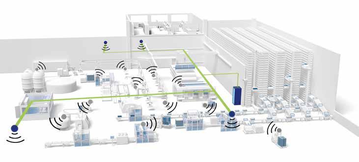
Despite different network concepts, Weczerek said that both wireless technologies are based to a large extent on the same basic technologies and thus offer comparable advantages compared to previous technologies: more reliable, more real-time capable, larger networks with more devices and much more data throughput. However, much more decisive than the technologies themselves is the use of free, undisturbed transmission channels.
11.2022 industrial ethernet book
“This is a clear advantage of 5G, that it makes it possible for the first time to operate private networks in their own protected frequency range. WLAN must continue to use public frequency bands even with Wi-Fi 6. But with the opening of the 6 GHz band in many countries, in some cases up to 1,200 MHz of additional bandwidth is available with a maximum of 59 new, largely still unused transmission channels. Therefore, 5G but also Wi-Fi 6 will play a key role in the further digitalization of the factory,” he said.
He added that 5G and Wi-Fi 6 are new communication standards based on a variety of new technologies that improve reliability, real time, performance, and efficiency. Both wireless communication standards, 5G and Wi-Fi 6, can be used very universally because they can be optimized very flexibly to meet individual requirements. Either the real time of small data packets, high data throughput or battery-saving communication with IIoT sensors or a mixture of all is important.
Targeting smart factory applications
“Today, wireless solutions are often used within applications where wired communication is not possible. Wireless is thus usually only a selective problem solution within the factory, often with limitations in real-time
“5G and Wi-Fi 6 are expanding the application possibilities for industrial wireless in the smart factory. These are clearly the latest generations of wireless technologies: for cellular communication it is 5G and for WLAN it is Wi-Fi 6 (IEEE 802.11AX). In the future, both have the potential to be a game changer for the broad use of wireless communication in the smart factory." Jürgen Weczerek, Manager Product Marketing Wireless and Security, Phoenix Contact
and safety communications. The new wireless technologies such as Wi-Fi 6 and above all 5G enable a complete wireless communication infrastructure within a factory, including real-time and safety communication,” Weczerek said. “In the future, they will be able to replace wired network connections to the greatest possible extent, thus offering greater flexibility and significantly lower connection costs per network device. This makes it possible to easily integrate sensors and intelligent devices everywhere in the network, so that big data, predictive maintenance, cloud connection, etc. become possible easily and economically.”
He added that, with 5G and Wi-Fi 6, data throughput, real-time characteristics and reliability have also improved significantly, which often limited their possible applications with current technologies. In particular, the availability of exclusively usable frequency ranges with 5G or additional transmission channels with Wi-Fi 6 often make it possible to implement larger and more reliable wireless networks in the factory in the first place.
“In addition, the new technologies offer significantly more options for meeting specific application requirements. However,
they are also more complex than the previous technologies, so that specific know-how is required for the planning, implementation, and operation of such wireless networks. This is especially true for 5G and its many options. Anyone planning to deploy such networks should therefore involve specialists,” he said.
Leveraging wireless speeds
Dramatic increases in wireless communication throughput.
According to Dr. Al Beydoun, ODVA President and Executive Director, recent advances in wireless network speed and reductions in latency have fundamentally altered communication. Wireless cellular technology has moved from 3G at 20 Mbit/s speed in the 2000s to 5G at up to 20 Gbit/s speed today, with generational advances taking place approximately every decade.
“The past three Wi-Fi specifications have been released about five years apart, with Wi-Fi 4 allowing download speeds of 600 Mbit/s and Wi-Fi 6 enabling speeds of up to 9.6 Gbit/s. While the generation advancements for both of these technologies have taken place at a linear rate, the speed has increased at an exponential
SOURCE: PHOENIX CONTACTrate,” Beydoun said. “This dramatic increase in wireless communication speed has enabled plant wide wireless networks in automotive for advanced diagnostic analysis and remote connectivity of machines such as palletizers in packaging facilities and instrumentation in oil and gas fields for remote monitoring to support maintenance.”
Wireless communication initially enabled voice for business, then grew in capability to transport data, including video, for business and automation and finally is poised to be a viable solution for control in automation, especially with private and hybrid network option availability for 5G. The next frontier in the continued progression of wireless networks is widespread control in both discrete and process environments, which will get a significant jumpstart from the new 5G and Wi-Fi 6 technologies.
“Wireless communication in an automation environment allows for potential installation cost savings due to reduced need for physical cabling, increased connectivity of devices and instrumentation providing for additional diagnostics, and decreased challenges in routing cables in applications with a high degree of movement such as those requiring tool changers,” Beydoun said. “Additionally, wireless communication enables increased production flexibility with machines and devices becoming easier to move to allow for different products or batches to be made and new motion options including drones and Automated Guided Vehicles (AGVs).”
He added, however, that security is a challenge that must be addressed in order for wireless to truly be viable in automation control applications. New exploitation opportunities can open up from outside the walls of a factory or gates of a plant with wireless. Stray signals can be mitigated with radiating cable and smart placement of the antennae. However, it is very important to authenticate transmitting nodes, to encrypt traffic, and to ensure that configurations cannot be changed without a password or key. As a part of a defense in depth solution, device and edge control level automation traffic can be further protected via solutions such as the CIP Security™ network extension for EtherNet/IP.
Cutting-edge wireless technology
The EtherNet/IP™ industrial communication network communicates data between devices and instruments at the application layer of the ISO/OSI model, using the Common Industrial Protocol, or CIP™ protocol. CIP information is then encapsulated in the transport layer, which use either TCP for larger data packets such as diagnostics or UDP for smaller, more time sensitive data packets such as I/O for EtherNet/IP.
At the network layer, logical addressing Internet Protocol (IP) information is added
Zigbee (802.15.4) 0.25 Mbit/s 40-350 ms Mesh 10-20 m
Bluetooth (802.15.1) 1-2 Mbit/s 40-100 ms Point-to-point 2-5 m
Wi-Fi 3 (802.11g) 3-54 Mbit/s 1-4 ms WLAN 35-100 m
Wi-Fi 4 (802.11n) 72-600 Mbit/s 1-4 ms WLAN 35-100 m
Wi-Fi 5 (802.11ac) 433-6933 Mbit/s 1-4 ms WLAN 35-50 m
Wi-Fi 6 (802.11ax) 600-9608 Mbit/s 1 ms WLAN 35-50 m
5G* 100-20,000 Mbit/s 1 ms Large Area Wide Area
to make the packet ready for network access. In the datalink layer and the physical layer, the packets are converted to the transmission media. This approach of communicating data via CIP, independent of the transport, network, datalink or physical layers, makes use of different transmission media possible. Therefore, EtherNet/IP can be used across copper, fiber, and wireless to provide users with a high degree of flexibility for use across numerous industrial applications.
Additionally, safety can be provided in wireless applications due to the black channel principle, which requires safety devices to have enough compute, intelligence, and diagnostic capability that the entire factory communication network has zero impact on the ability of the safety devices to detect communication errors.
This means that the physical transmission medium is just another part of the black channel. Application layer safety solutions, such as the CIP Safety™ network extension for EtherNet/IP, can provide fail-safe communication between nodes such as safety I/O blocks, safety interlock switches, safety light curtains and safety controllers in both machine and process automation safety applications up to Safety Integrity Level (SIL) 3 according to IEC 61508.
“One of the clearest examples of the value of wireless control is for AGVs that transport materials around a factory or warehouse. It’s very costly to create a physical track on the floor for an AGV to travel on and this cost multiplies when process changes require new layouts,” Beydoun said. “Welding cells within
automotive have also adopted wireless control in order to remove some of the challenges of electrical interference and running cables in tight spaces with a high degree of movement.
Process automation has long leveraged wireless control for connectivity between remotely located and spread-out instrumentation that are a part of wind farms or oil and gas fields. Additional possibilities include using less cable for hygienic design in food and beverage applications, modular and flexible plant design to prepare for Industry 4.0, and adding data collection sensors to legacy devices for IIoT analysis.”
He added that automation engineers are tasked to leverage new communication technology, such as wireless, to help alleviate labor shortages, to drive down costs, to and to increase output and quality. The ability to utilize wireless AGVs to complete low value add tasks in factories such as moving parts frees up workers to do other more complicated and challenging installation and assembly work that machines cannot do well. Wireless can also enable connection of remotely located or legacy devices, which can provide valuable diagnostics and prognostics that can help to optimize OEE.
“Wireless technologies such as 5G and Wi-Fi 6, among others, will help to drive the increased speed and reduced latency that industrial applications demand. Wellengineered design that takes into account both safety and security will help make wireless the new normal in factories and plants around the globe,” he added. “EtherNet/IP will be one of the key industrial communication
protocols that will enable this change due to its media independence enabled by CIPTM communication.”
Driven by Industry 4.0 application requirements
Joseph Cheng, Sr. Product Manager of IIoT Development Div. for EtherWAN, told IEB that industrial wireless solutions are a critical element in the development of IIoT networking solutions.
“The Industrial Internet of Things (IIoT) is a step towards making traditional factories into smart spaces. The latest industry trends have been towards greater efficiency and reduced maintenance costs. To this end, there has been an increase in the adaptation of Network Management Software (NMS),” Cheng said. “These NMS systems have proven to be very effective in reducing the labor transportation costs related to switch maintenance. Another important trend is automatic backups when a problem occurs on a device. Lost data equals lost money in many cases. The latest transmission devices are designed with automatic backup functionality.”
“Eventually, existing fixed network technologies will not be able to effectively manage the requirements of Industry 4.0. Identifying and alleviating issues with cellular network capabilities will more than offset the switching costs, and this will prove the practical and financial value of these new networks,” he added.
IIoT creating opportunities for wireless applications
Industry 4.0 opportunities

Cheng said that Industry 4.0 has created opportunities for expanded industrial wireless solutions and capabilities. IoT devices have various sensors that can monitor the temperature, vibration, voltage, currents, and more. So, these sensors can help with early warning signs of any predicted malfunctions, creating a safer workplace.
It is then critical to create policies and procedures specific to wireless technologies that will become part of the overall corporate information Technology (IT)/operational Technology (OT) strategy. Manufacturers will come to adopt these newer applications and systems as their benefits become increasingly apparent.
“The most important benefit is the flexibility to add devices without making major changes to the network infrastructure. This means the deployment of new devices is easier and cheaper than ever before,” he added.
“This is a key issue when connecting facilities that are physically distant. However, compare with wired infrastructure, cybersecurity risks will become the next problem that cannot be ignored, as with the expectation for remote data access, the focus on cybersecurity is going to carry forward into 2022 and beyond.”
In field sites, IIoT devices connect with edge sensors and meters that generate high volumes of data. Organizing and processing data at the front end will gain the efficiency
of backend data management and save cost on transmission.
Connectivity among edge devices and backend SCADA is the one of the vital aspects of success. Reliable connectivity by 4G LTE and VPN is vital to ensure the right data is transferred between systems and equipment uninterruptedly.
Cutting edge technology
Cheng added that, to avoid the worst climate impacts, global greenhouse gas (GHG) emissions must be slashed in half during the next decade and reach net-zero early in the second half of the century.
“A good example of the unique applications of cellular wireless technology is in the ability to set up systems that can monitor and calculate the amount of carbon dioxide produced by manufacturing processes. These calculations are not just per facility, but can finely detect and record CO2 emissions per second,” he said.
In a manufacturing system, a process plan is the combination of diverse production processes and operations. Due to the different processes employed, even a small change in product process design, the impact on the environment will be very different. Also, the carbon emissions caused by auxiliary resource and energy consumptions are mainly including the electrical energy consumption of ancillary equipment in manufacturing plant, for example, lighting, heating, and ventilation.
“Once quantitative values are determined for each unit process and breakdown of carbon emission, a range of improvement opportunities can be identified to monitor the resource and energy consumptions during the entire process planning. Each improvement opportunity has been linked to a positive effect on at least one previously identified carbon emission,” he added.
Industrial wireless solutions and challenges
Connectivity between edge devices and backend SCADA sensors is a vital aspect of a successful integration of the latest wireless technology. Furthermore, reliable connectivity through cellular LTE and VPN connections is vital to ensure the uninterrupted transfer of data between systems and equipment.
The future trend is towards low latency wireless communication technologies that can bridge the gap between existing systems, and become the key motivator for the widespread penetration of wireless communications in automated industrial systems.
“The main challenges faced by automation engineers are meeting the demands for increased efficiency and cost reduction, while also satisfying the need to bring the latest technologies to the field quickly. The industry’s latest industrial wireless solutions satisfy both the need for efficiency, and the required ease of deployment, allowing them to connect legacy SCADA systems with MQTT,
for a smooth and uninterrupted data flow,” Cheng said.
“The benefits of factory automation are now well understood. However, these new systems present challenges that are less wellknown, and poor implementation can lead to lackluster results. The challenges include high setup costs, unrealistic ROIs, and problems regarding integration and scalability,” he added. “Additionally, overall system flexibility and competent staffing issues need to be taken into account. While none of these issues are insurmountable, managers need to understand both the benefits and possible pitfalls to achieve successful deployment of these technologies.”
Focus on Industrial 5G Future proof industrial cybersecurity solutions.
According to Sander Rotmensen, Director of Industrial Wireless Communication for Siemens AG, Industrial 5G will continue to expand its role in industrial wireless applications.
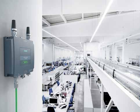
“Demand for more flexibility has grown for years now, therefore wireless technologies have become more important. Around 15 years ago, wireless technologies emerged as the application of choice over slip rings and flexible cables. At that time one of the driving technologies was Wireless LAN, also called Wi-Fi. Demand for Wireless LAN solutions is still growing, especially with the release of the first Industrial Wi-Fi 6 products and the introduction of the new spectrum in the 6 GHz band.” Rotmensen said.
“Therefore, this technology will continue to play an important role in the factories of today and tomorrow. In addition, 5G or to be more specific Industrial 5G, the first cellular technology developed to also fulfill industrial requirements, will play an important role in the future.”
Industrial wireless advantages
“With Wi-Fi 6, we see benefits with regards to latency in a single radio cell while Wi-Fi 6E opens the possibility to use the 6 GHz band, a whole new spectrum range,” Rotmensen added. “When talking about 5G for industry, the biggest benefit is the possibility to set up private networks utilizing licensed spectrum, as well as the future support of reliable low-latency communications. Those are tremendously important to support the flexible factory of tomorrow.”
Rotmensen said that one example would be the lower latency, which can be achieved with Wi-Fi 6 through OFDMA (Orthogonal Frequency Division Multiple Access). It allows an Access Point to send data to up to nine connected clients at the same time. Unfortunately, the standard is not addressing all the industrial needs. Therefore, special
and 5G are
industrial enhancements are offered, our so-called iFeatures.
With these features enabled, real-time communication becomes a reality, so we can support wireless safety applications. In addition, the Target Wake Time feature helps to schedule the traffic in a certain cell, which allows lower reaction times and saves power on the wireless interface. Additionally, this can be combined with a so-called sleep-mode and an integrated digital IO. This could power down for example a complete AGV, which is very useful when it comes to battery operated vehicles.
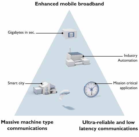
5G addresses three main scenarios: Enhanced Mobile Broadband (eMBB), Massive Machine-Type Communications (MMTC) and Ultra-Reliable Low-Latency Communications (URLLC). EMBB focusses on high bandwidth applications, which are used in our daily lives, but also for remote communication of machines and plants.
MMTC will be focusing on connecting a high number of end-devices, which is interesting in process industry where massive wireless sensor networks are becoming a really interesting possibility.
For discrete manufacturing however, URLLC is very interesting. It will enable ultra-reliable low-latency communications, supporting real-time communication that is necessary for safety applications such as emergency stops.
Industrial wireless solutions
Rotmensen added that, when looking at where we came from a couple decades ago, we mainly
saw a focus on increasing the amount of data that can be transmitted in a certain amount of time. This is great when using the technologies at home or in the office. But when looking at industrial usage of wireless technologies, the focus needs to be on reliability and lower latencies.
With Wi-Fi 6 we have seen some progress over the previous versions and with 5G we have the first technology that has been developed focusing on ultra-reliable low-latency communications. These are very promising developments, that will allow even more applications to be supported with wireless technologies in the future.
“One of the biggest challenges is the ability to support mobility and flexibility in the factories today and even more so tomorrow,” Rotmensen said.
“With the next generation of the wireless technologies Wi-Fi and 5G, we can tap into a larger amount of spectrum. This makes it easier to set up larger wireless networks with more end-devices being connected. It also enables us to have networks supporting a combination of mission-critical applications instead of just a single one.”
“Thanks to Wireless LAN and 5G technology, new possibilities are becoming available. The newer iterations of these technologies are now being developed with the needs of the industry in mind as well. All in all, a promising outlook for the future of flexible factories in which I can’t wait to see how these technologies will help us overcome today’s limitations,” he added.
Reliable wireless connectivity
Ultra-reliable wireless backhaul technology solution.
According to Alice Masini, IoT BU - Product Manager for Cisco, key technology trends are helping to enable industrial wireless solutions and applications that are making an impact in the modern factory.

“In every industry, organizations are accelerating their digitization efforts, deploying more automations, and looking for new ways to increase productivity. In manufacturing, we see more and more autonomous guided vehicles (AGVs) and autonomous mobile robots (AMRs) being deployed. In mines or ports, tele-remote operations of cranes, tractors, and dozers is a major trend. These assets need highly reliable wireless connectivity to access their control systems,” Masini said.
She said that Private 5G is now in everybody’s mind, and it is very promising. But it is still not available everywhere and it comes with spectrum, cost, and complexity issues that might be out of reach to many organizations. Private 5G also has a few drawbacks: its ultra-low latency (URLLC) profile is still not available and will offer throughputs of just a few Mbps. So, it is not ideal for these use
cases which require both high bandwidth and low latency.
“The key to enable these new industrial applications is to combine several wireless technologies, choosing the ones that best meet the operational requirements. In addition to Wi-Fi 6 and 5G, Cisco offers its URWB technology that is as easy to deploy and use as Wi-Fi, supports mobility use cases with fewer access points and ultra-low latency even at Gigabit speeds,” she added.
Industrial wireless benefits Masini said that industrial control networks need very high reliability and very low latency, so control loops can run faster, 24/7, enabling manufacturing organizations to grow production outputs. Previously, wireless was mostly used to connect tools, sensors, or handheld devices. Today, critical assets are being connected, so new wireless technologies must meet these requirements as well.
Another major change is that some of these critical assets are now mobile, such as AGVs and AMRs. So high reliability and low latency must now also be ensured on the move with seamless roaming and zero packet loss during handoffs. This is quite a challenge in these industrial environments where harsh conditions, metallic structures and high asset
density can create a lot of interferences and issues.
In addition, wireless technologies have a role to play in improving the power consumption of industrial assets. This helps reduce costs as well as improve the sustainability KPI that many manufacturing organizations are now tracking. Only a reliable, predictable, and controlled wireless infrastructure can help optimize the power consumption of every single asset.
“In manufacturing, AGVs and AMRs are deployed to move materials within the factory, and to/from the warehouse, without any driver being involved. Wireless can also be used to quickly reconfigure the production environment or deploy additional machines, sensors, and PLCs to cope with a need of additional resources,” Masini said.
In ports, handling vehicles and cranes are all controlled by complex software tools called terminal operations systems (TOS). They transmit container pictures to optical character recognition (OCR) tools, send their geolocation in real-time and immediately receive instructions on what their next task is. Autonomous vehicles and remotely operated cranes are becoming a reality and send HD video streams to their control platforms. Modern port automation requires reliable wireless technology that can provide perfect radio coverage, low latency, seamless handoff, and high bandwidth.
Finally, workers safety becomes a major key point in some use cases; hazardous conditions monitoring in Oil & Gas or support for anti-fatigue systems in mining, for example, are critical applications which can only be supported by cutting-edge wireless technologies.
Industrial wireless challenges
Masini said that radio interference, high device density, and the need for resiliency, high throughputs, and low latency are probably the main challenges to solve when deploying wireless technologies in modern industrial environments.
The Wi-Fi 6E standard (offering up to 1.2 GHz more spectrum) and even the 5G enhanced Mobile Broadband Profile (eMBB) can address the need for increased throughput while solving concerns regarding interferences and high-density support.
“Low latency and high reliability are key to enable resiliency and are required to support these time-sensitive critical applications. The challenge is even higher when connected devices are moving at high speed, so technologies like the Cisco Ultra-Reliable Wireless Backhaul come into play to support these use cases,” she said.
“Overcoming these challenges is not a mirage anymore, and industrial automation can now benefit from reliable wireless
technologies to enable more automation and increase the efficiency.”
Importance of selecting the right network topology
Reliability and efficiency with mesh networking.
Phil Beecher, CEO and President of the Wi-SUN Alliance, told IEB that selecting the right network topology is critical for industrial applications.
“Wireless communications have been used in industrial environments for many years, but with the development and deployment of standards-based wireless connectivity technology, this is driving the uptake of more advanced applications in factory settings using IoT and IIoT sensors and devices,” Beecher said. “Industrial processes should be efficient, reliable and consistent, meeting well-defined minimum requirements. Designing IoT/IIoT applications and sensors to support a known manufacturing or factory environment should be straightforward. In particularly harsh or hazardous environments for example, devices can be deployed and will just continue working.”
Beecher said that, for a designer of wireless communications, selecting the right network topology is important, and within industrial environments in particular, it is critical to ensure reliability and efficiency. A mesh networking topology provides both reliability and efficiency, as well as scalability and interoperability within these tough
environments.
“In a recent Wi-SUN Alliance study, we found that IoT adopters (across a range of industries) are keeping their connectivity options open and looking at multiple network topologies. But there is a general trend towards mesh-based networking, which lost no support among those wanting to use it exclusively over the last 5 years. Star topologies, however, lost traction, with 12% preferring it, down from 21% in 2017,” he said.
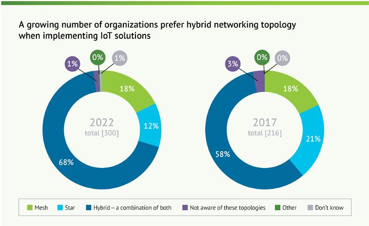
Looking specifically at the benefits of wireless mesh technology, it means each device or sensor on a network can speak to other devices, allowing its messages to travel a long distance – hopping between each node in the network.
“Unlike indoor personal area mesh networks (PAN) such as ZigBee and Thread, Wi-SUN FAN (Field Area Network), for example, is specifically designed for a much greater scale of endpoints that will hop over much greater distances to suit smart utilities and industrial environments,” Beecher said.
As an open standards technology, it is based on the IEEE 802.15.4g specification, as well as other IEEE 802 and IETF standards. Developed and promoted by Wi-SUN Alliance, this ensures that devices from multiple vendors conform to the FAN specification and meet the requirements for interoperability.
He added that there’s no room for failure, which is so critical for industrial environments. Mesh networks, like Wi-SUN FAN, when deployed with sufficient density, will have
multiple paths back from the end-device to the backhaul network via a router (aka border router) that links it to the Internet of a private wide area network. Wi-SUN FAN is self-forming, which makes adding new devices easy, and self-healing, so that if a pathway fails, the network will automatically re-route to the gateways.
Beecher also mentioned specific application areas that the newest Industrial Wireless solutions are targeting:
• Difficulties with dust and harsh environments are strong incentives to use the technology. In hazardous environments, IoT can be used to keep staff safe, and to help ensure consistency in the production process.
• IoT sensors can be used for predictive maintenance and early detection of faults, wear and tear in machines and parts and anomalies in behaviour, helping to reduce maintenance costs, as well as machine replacement.
• IoT can be used to improve manufacturing security, by ensuring that raw materials are of the right quality and grade, such as in making steel or concrete, and ensuring the end product is fit for purpose for building and critical infrastructure.
• Sensors can also be used to ensure the integrity of safe and unsafe areas, for example, where airflow is monitored for particles in food manufacturing where risk of cross-contamination is critical.
Al Presher, Editor, Industrial Ethernet Book.
Industrial 5G implementations get closer every day
5G offers promising performance enhancements for consumer applications, with up to 20x more throughput than 4G and up to 100x more users in a single cell. But industrial applications will benefit far more from the boost in 5G performance, even though industrial applications have a different set of network requirements.
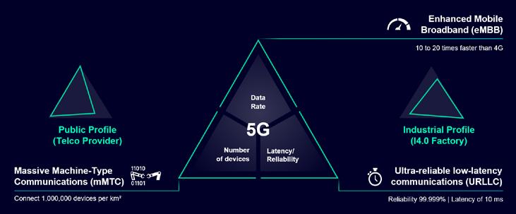
5G IS STARTING TO APPEAR EVERYWHERE IN our daily lives – on the display of your new smartphone, on billboards, in newspapers or TV-commercials, to name just a few. And although 5G offers promising performance enhancements for consumer applications – with up to 20x more throughput than 4G and up to 100x more users in a single cell –industrial applications will benefit far more.
Industrial verticals have different requirements to a network than consumers have in a public 5G network. One typical example is that industrial robots or automated guided vehicles (AGVs) communicate a low amount of data, however safety and efficiency demand really low latency and a high reliability.
The three scenarios of 5G
The different requirements of the industrial verticals are addressed by the three main scenarios of 5G: enhanced Mobile Broadband (eMBB), massive Machine-Type Communications (mMTC), and Ultra-Reliable Low-Latency Communications (URLLC).
The first scenario, eMBB, includes enhancements to 4G with the main objective of fulfilling data-driven use cases which require high data-transfer rates and global coverage. A typical example is the growing need for high quality, high-definition streaming of music
and video to mobile devices like smartphones and virtual reality (VR) glasses.
Massive Machine Type Communications, the second scenario, focuses on having more devices in a smaller area. An use-case example are IoT-applications (Internet of Things) where a large number of connected sensors and devices send and receive data infrequently and are deployed in a small, defined area.
The third scenario is the most demanding. The typical mission-critical applications using URLLC require high reliability and low latency. Examples include mobile robots, autonomous logistics, automated guided vehicles (AGVs), and safety applications in industrial environments.
However, full implementation of these three scenarios is not possible simultaneously within the same network. A network can only be designed and configured in such a way to optimally support one use case. For example, it can offer either the highest possible data rate or the lowest possible latency. Achieving both at the same time on the same network is impossible.
Public or Private 5G?
This is where different necessary implementation approaches for 5G networks are most obvious. A public 5G network is typically set up to provide high bandwidths for
e.g video streaming, and other data-intensive applications.
However, for most factory applications, bandwidth plays a minor role. The clear emphasis here: reliability and ultra-low latency in the communication network. Fortunately, private networks are an integral part of the 5G standard. They enable companies to establish their own local 5G networks and adapt them to their mission-critical applications.
For this purpose, the German Federal Network Agency (Bundesnetzagentur) has reserved part of the frequency spectrum for use in private, local 5G networks. To be more specific, a total of 100 MHz is set aside between 3,7 – 3,8 GHZ and in the mmWave band an additional 800 MHz in 26 GHz. This private spectrum can be obtained for the setup of local campus networks for a reasonable fee. A network utilizing 100 MHz of C-Band spectrum – which covers a plant from 150.000m² – would cost 5,500 Euro in total for 10 years.
This initiative from the German Federal Network Agency was the start of many countries looking into allocating private 5G spectrum for local use. Most are intended to support the roll-out of local private 5G networks in different industrial verticals. Until September 2022 in Germany, of the 249 requests for private 5G networks, 243 were
granted. Most of these private 5G networks are Proof-of-Concepts to assess the benefits of 5G over existing technologies. Beside the fact that in industry typically only proven technologies are used, there are two further reasons why companies hesitate with the roll-out of Industrial 5G networks in production.
5G availability
Reliable availability of products with the right feature set is a major concern. 5G is not a single development, but comes in multiple iterations called releases. In December 2018, Release 15, the first release of 5G was completed by the 3GPP. The latest release available now is Release 17.
However, products for industrial use are not yet widely available. The main reason for this is that it takes about three years to move from a finished release to a finished product that can be used in harsh industrial environments. What’s more, most of the industry specific features are part of the newer releases – and products follow roughly three years after the corresponding release. A further concern is that the 5G user equipment ecosystem is insufficiently developed. A quick look at the number of available 5G devices results in a list of Industrial 5G routers, smartphones, and some tablets. Only recently, we’ve seen interest from vendors to equip laptops with 5G, but typical industrial devices, be it a connected screwdriver, a handheld scanner/ reader, are yet to become available. However, once this has been resolved an uptake in the number of installed private Industrial 5G networks is to be expected.
Industrial 5G
And then there is another challenge: how to bring a technology driven by telecom companies into industrial verticals, where the leading technologies are Ethernet and Wireless LAN. A private Industrial 5G infrastructure
solution designed to meet the needs of industrial use cases is the answer. The hardware needs simultaneously to be compact – for installation in the field – maintenance free and withstand harsh industrial environments.
Furthermore, a simple and understandable user interface for daily operation of the network is essential. All this is currently in development and being tested by Siemens with a prototype private Industrial 5G network. The resulting network is a compact solution that runs on Siemens Industrial PCs. These Industrial PCs run both the 5G Core and a part of the Radio Access Network (RAN).
The 5G Core manages the complete 5G network including the RAN. The RAN consists of three different elements: the Central Unit (CU), the Distributed Unit (DU), and the Radio Units (RU). The CU connects the 5G Core and the DUs and provides high-level coordination of the 5G radio network. The DU converts the data packets into a digital radio signal. The RUs are the network’s radios, and they convert the digital radio signals sent and received into a radio signal.
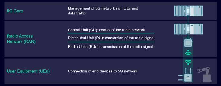
User Equipment (UEs) is not part of the private 5G infrastructure, but connects to it like the smartphones we use every day. However, in industry it’s typically Industrial
Enabling the implementation of industrial 5G
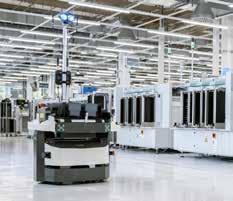
After prototype testing of our private 5G solution in the Automotive Showroom and Test Center in Nürnberg, the time came to start implementing it into a live production plant. Siemens Manufacturing Karlsruhe (MF-K) often implements innovative solutions that push boundaries.
MF-K is located in the Siemens Industrial Park in Karlsruhe, one of Germany’s most technology-driven regions. Over 37,000 m², approximately 1,000 employees manufacture 24,000 assorted products for Siemens’ global customers. Examples range from automation and process control systems to switches, Industrial Wireless LAN access points, Industrial PCs, and now Industrial 5G routers.
With so many diverse products, workers must be equipped with the tools, raw materials, and semi-finished products they need – just when they need them. Autonomous Mobile Robots (AMR) play a huge role in this. They require reliable wireless connectivity and that led to the implementation of our prototype private 5G solution. A complete setup with Core, CU, DU and RUs has been installed to provide network coverage in the areas where the AMR is active. The AMR connects to the network with a SCALANCE MUM856-1 5G router.
By testing and operating these products in our own manufacturing facility, we are developing a reliable private 5G solution to be available on the market soon and enable the industrial use cases of today and tomorrow.
Addressing reliability issues in industrial wireless networks
Industrial wireless technologies are indeed required to enable autonomous and remote-controlled robots and vehicles, to improves collaboration between mobile workers and increase the overall efficiency and safety of an industrial system. Reliability is a key issue for all of these applications.
DIGITAL TRANSFORMATION IN AUTOMATION IS
driving a rapid growth of industrial networks. Vehicles and robots are getting autonomous, and more than ever reliable wireless technologies play a key role in supporting mission critical IoT applications. Moving assets cannot tolerate dropped connections or network latency. A glitch could jeopardize safety and compromise the OT process. Even connecting fixed assets isn’t always easy. Fiber isn’t available everywhere and it can be too expensive to deploy and maintain.
To address these complex fixed and mobile use cases, Cisco has developed the Ultra-Reliable Wireless Backhaul (URWB) technology. It provides multi-gigabit fiber-like performance, connects moving assets, links locations that are a few miles apart or need temporary connectivity. Because the underlying technology is Wi-Fi, it provides complete control over the network and uses unlicensed spectrum, reducing costs and complexity and making it easy to deploy pretty much anywhere.
Connecting critical industrial assets requires advanced wireless technology
Cisco URWB is a wireless backhaul technology derived from Wi-Fi and designed to serve mobile network environments such as trains, buses, subways, remotely controlled cranes, autonomous guided vehicles (AGVs), and autonomous mobile robots (AMRs). It can also be deployed as a fixed infrastructure, providing backhaul where fiber can’t go or is too expensive.
Cisco URWB technology provides low-latency (<10ms), highly reliable (up to 99.995%), long-range, high-bandwidth connections that
can handle endpoints moving at high speeds with seamless handoffs and zero packet loss.
This is possible thanks to Cisco’s MPLS-overwireless link protocol, created to overcome the limits of standard wireless protocols when transmitting any IP-compatible traffic with very low latency in a mobility context.
It brings a ‘make-before-break’ procedure, enabling moving vehicles to establish a reliable connection with the next Access Point along its path before losing connectivity to the current one.
Cisco URWB networks can be designed for Layer 2 use cases (such as when connecting AGVs or AMRs in a factory floor) as well as Layer 3 use cases (such as for train-totrackside communications in subways or railways), allowing the network to scale in size without compromising reliability and availability.

A Cisco URWB topology is shown in the graphic above. The radio onboard the vehicle is connected to fixed access point in charge of backhauling traffic from mobile assets to the infrastructure. Data from the vehicle is
encapsulated on a centralized MPLS gateway and then decapsulated as IP packets on the IP network.
Recent enhancements were made to Cisco URWB to deliver uninterrupted connectivity to fast-moving devices by sending highpriority packets via redundant paths. In fact, Cisco’s patented Multipath Operations (MPO) technology can duplicate protected traffic up to 8 times and avoid common paths.
This functionality, combined with the hardware capabilities, can further reduce the latency, improve reliability, addressing both interference and hardware failures.
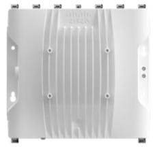
Earlier this year, Cisco launched the Catalyst IW9167E Heavy Duty Access point. It supports Cisco’s Ultra-Reliable Wireless Backhaul technology as well as Wi-Fi 6.
The dual-mode capability brings the flexibility to decide which technology to use depending on the project requirements. The operational mode can be swapped in the field, to be able to adapt the product to the specific use case, facilitating the transition between the two technologies and optimizing the investment.
Industries embracing wireless networking
Industrial operations have long required wireless networking to connect mobile workers and machinery where wired networking was not a feasible option. But as wireless technologies have improved, use cases have become more numerous across all industry verticals.
Cisco URWB has been helping numerous industrial organizations around the World to address these use cases for years.
In Italy, La Spezia Container Terminal
deployed the URWB technology to connect all mobile assets such as Ship-to-Shore cranes (STSs), Rubber-Tyred Gantry cranes (RTGs), stacking cranes, reach stackers, and terminal tractors creating a private mobile wireless backbone offering ultra-low latency and seamless roaming. It has solved coverage and network downtime issues that LSCT was experiencing with traditional Wi-Fi. Moreover, the number of access points required to create the backbone has been dramatically reduced, making the new solution much easier and cheaper to manage.
In Texas, the Canutillo Independent School District deployed the URWB technology to connect Wi-Fi hot spots in remote locations with poor Internet coverage so thousands of students could do distance learning from home during the COVID-19 pandemic.
At the Kennedy Space Center, a Dallara AV-21 race car involved the Indy Autonomous Challenge (https://www. indyautonomouschallenge.com/), set a new World record for the fastest autonomous car, sustaining speeds of over 192.2 mph (309.3 kph). All engaged race cars were connected using Cisco URWB technology, enabling high bandwidth, ultra-low-latency, reliable connectivity to their control systems so they could make sub-second decisions even at highspeeds.
Conclusion
Cisco Ultra-Reliable Wireless Backhaul is a breakthrough in private mobile wireless networking. It is as easy to deploy and manage as Wi-Fi, and offers cost-effective, high bandwidth, ultra-low latency, and high availability connectivity required to enable these new use cases. It’s the perfect technology to drive the highest level of automation in industrial networks.
Alice Masini, IoT BU - Product Manager, Cisco.
Visit Website
Industry Wireless Use Cases
Manufacturing
• Using Automated Guided Vehicles (AGVs), robots (AMRs), and other mobile equipment on the factory floor
• Providing reliable voice, video, collaboration, and Augmented Reality and Virtual Reality (AR/VR) tools to the factory workforce
• Controlling rotating and conveyance systems
• Downloading software and data to manufactured products
• Supporting mobile Human-Machine Interface devices (HMIs) and handheld tooling
Connected rail
• Communications-Based Train Control (CBTC)
• Onboard connectivity (passenger Wi-Fi, workers’ access to applications, live ClosedCircuit TV (CCTV), digital displays, Point Of Sale (POS) for onboard purchases, etc.)
• Vehicle telemetry and real-time asset monitoring, including track infrastructure
• Station passenger services such as Wi-Fi, wayfinding, and digital kiosks
Ports and terminals
• Connecting cranes and handling vehicles to Terminal Operating Systems (TOS)
• Using tele-remote devices (Rubber-Tired Gantry (RTG), ship-to-shore, and quay cranes and straddle carriers)
• Enabling autonomous operations (AGVs, AMRs, etc.)
• Providing voice, video, and collaboration applications for terminal workers and visitors
• Enabling port access control, traffic management, and video surveillance
Mining
• Connecting mining equipment and control systems
• Enabling autonomous operation of mining equipment
• Providing voice, video, and collaboration applications for mine workers
• Providing access control and video surveillance
Oil and gas
• Monitoring remote operations equipment
• Connecting and controlling midstream assets
• Performing video surveillance in large, distributed sites
Connected communities (smart and safe cities)
• Connecting sensors that monitor conditions around the city such as public transport, traffic, etc.

• Providing Wi-Fi access points in public areas such as parks, libraries, etc.
• Installing CCTV for public safety
• Providing short-term networking needs for special events
60 GHz wireless data interconnect for slip rings
High performance integrated and discrete RF and microwave components can be implemented across the entire frequency spectrum to enable application specific designs for a contactless Gbps-level data transmission via rotary joints.
THE FOURTH INDUSTRIAL REVOLUTION DRIVES digital manufacturing forward by implementing new scenarios into the production process. These scenarios rely on fundamental design principles that include device interconnection, information transparency, technical assistance, and decentralized decisions. The realization of all these principles in modern smart factories would not be possible without advanced wireless communication technologies. They enable multifaceted applications for a broad range of areas including process automation, asset tracking, machinery control, intralogistics, and infrastructure networking.
Smart factories incorporate various cyberphysical systems that require faster and more reliable wireless solutions to handle ever increasing amounts of data in the toughest industrial settings. The main drivers facilitating new developments of these solutions to be deployed in highly demanding Industry 4.0 scenarios include the implementation of mobile SCADA, replacement of legacy systems, and realization of data transmission from moving equipment where it was not possible or was limited before. This article focuses on the wireless technologies driven by this latter aspect.
The first part of the article summarizes the main requirements imposed by modern industrial applications on a communication interface between mechanically rotating subsystems. The second part attempts to classify numerous data interface technologies employed in these subsystems today according to the type of mechanisms used to transmit data between a rotor and a stator. It gives a concise overview of these technologies and discusses their main advantages and disadvantages. The third part of the article proposes a novel 60 GHz wireless solution for high speed, low latency communication that enables realization of advanced data interface architectures in slip ring assemblies to meet the demanding requirements of new industrial scenarios.
Industrial Requirements for Data Interfaces in Rotary Joints
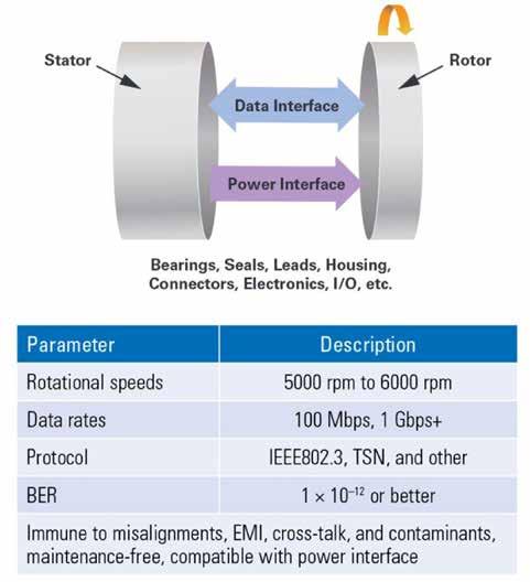
A rotary joint, also often interchanged with the term slip ring, is an assembly for transmitting data and power across a rotating connection (see Figure 2). The growing
Figure 1. Overview of the industrial revolutions.

need for faster and more reliable data transmission between rotating components in modern industrial scenarios imposes strict requirements on bandwidth, crosstalk, and EMI performance of the data interfaces used in rotary joints. Meeting these requirements is essential to guarantee real-time operation, continuous uptime, and maximum efficiency of the corresponding industrial equipment.
Industrial rotary data interface assemblies must ensure constant transmission quality at very fast rotational speeds of 5000 rpm to 6000 rpm at rates of typically 100 Mbps. In
most cases these data rates are sufficient, but some specialized applications require faster transmission at 1 Gbps and higher, which is becoming a fairly standard benchmark nowadays. Industrial applications also call for support of IEEE802.3-based (Ethernet) and other industrial bus protocols, as well as deterministic real-time communication, to permit time sensitive applications and IIoT functionality. Data interface solutions designed for these applications must be immune to physical misalignments, electromagnetic interferences, and crosstalk
Figure 2. Rotary joint—high level block diagram and requirements.
to enable error-free data transmission with bit error rates (BER) of 1 × 10⁻¹² or better. Contaminants present in the industrial environment should not affect the operation of a rotary joint that ideally must be maintenance-free and not suffer from wear. Finally, the data interface technology must be compatible with power transmission subsystem of a rotary joint assembly to meet all functional requirements of a target application.
Data Interface Technologies
There are different types of rotary joints that vary in terms of their functional features, form factor, rotational speeds (rpm), maximum data rate, power ranges, type of supported interfaces, channel count, and many other design aspects shaped by application requirements. Among these design considerations, the data interface has some of the most critical requirements and it is therefore crucial to make the right choice of technology for its implementation in a slip ring assembly. Data communication technologies used to realize this function can generally be classified into contacting and contactless. They abound with many variations depending on the type of coupling they utilize
in order to realize a communication channel for data transmission.
Contact-Type Interfaces
Contact-type solutions typically rely on composite, monofilament, or polyfilament brushes on a stator that slide against conducting rings on a rotor, thereby creating an uninterrupted passage of electrical signals between moving and stationary components (see Figure 3). The selection of brush type with regard to data communication depends on the signal bandwidth, data transfer rate, required
SOURCE: ANALOG DEVICESFigure 3. Contact-type slip ring. Courtesy: Servotectica/CC BY-SA 4.0.
11.2022 industrial ethernet book
transmission quality, operational currents, and rpm. Although this is a well-established technology that has been employed in slip rings since their invention, it has certain limitations. Reliability of contact-type slip rings suffers in harsh operating environments due to the presence of mechanical contacts requiring regular maintenance. Electromechanical rotary joints are also prone to electromagnetic interference. In addition to that, the characteristics of the physical media used to establish the contact interface, as well as various mismatch effects, have a strong impact on the channel bandwidth. Moreover, sliding contacts generate electrical resistance variation that degrades the transmission quality, which can be especially critical in high data rate real-time applications.
Contactless Interfaces
Contactless rotary joints overcome those limitations by using radiating or non-radiating electromagnetic fields to transfer the data across rotating parts. This technology offers several performance advantages over electrical signal transmission. The lack of mechanical contacts avoids contact wear requiring less maintenance and does not suffer from data loss arising from resistance at high rotational speeds.

Fiber Optic Rotary Joints
The most common example of a contactless solution is a fiber optic slip ring known as a fiber optic rotary joint (FORJ), which is schematically shown in Figure 4. FORJs rely on optical radiation to transfer data and operate typically at infrared wavelengths between 850 nm and 1550 nm allowing EMI-free transmission of every kind of analog or digital optical signal at very high data rates of several dozens of Gbps.
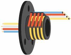
Figure 4. Fiber optic rotary joint. Courtesy: Servotectica/CC BY-SA 4.0.
However, fiber optic solutions are not without challenges. They experience strong extrinsic losses that result in signal attenuation caused by angular and axial misalignments. These misalignments are also the main contributor to rotational signal fluctuations that can be critical in some applications. Moreover, fiber optic rotary joints usually require high levels of protection in harsh industrial environments.
Inductive and Capacitive Interfaces
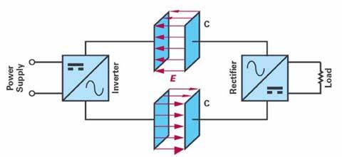
Another type of contactless technology is based on near-field coupling mechanisms realized through electric and magnetic fields generated by primarily non-radiating inductive and capacitive circuit elements in lower frequency bands of the electromagnetic spectrum.
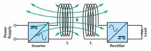
Inductive method applies the principle of electromagnetic induction to interface moving parts of an assembly. Slip rings using this type of coupling, which is schematically depicted in Figure 5, are useful for industrial applications with high rotational speeds but they are more suitable for transmission of power rather than for transmission of high speed data. They are widely used in wind turbine applications to provide electrical signals and power for blade pitch control systems, and in packaging applications where moving parts run at high rpm.
In contrast to inductive slip rings relying on a magnetic field, the slip rings based on capacitive technology use electric fields to transfer data between a rotor and a stator. The capacitive coupling method shown in Figure 6 offers the realization of a relatively low cost and light weight solution with negligible eddy current losses and excellent misalignment performance. This technology enables reliable data transmission at high speeds of several Gbps in harsh operational environments and independent of rotational speeds. Capacitive slip rings are often designed for a combination with Ethernet field buses and they are broadly used in time sensitive industrial applications.
Other Types of Interfaces
Apart from contactless slip ring technologies utilizing primarily inductive or capacitive coupling mechanisms, solutions relying on a combination of both types of mechanisms can be realized by using proper coupling structures
Figure 5. Inductive coupling.
Figure 6. Capacitive coupling.
such as waveguides or transmission line elements. There are also special types of slip rings: for instance, those relying on mercury as a conduction media. However, mercury-wetted slip rings have strict demands for operational environment settings and cannot be used at high temperatures, which makes them not suitable for industrial use cases.
The broad spectrum of all discussed data interface technologies summarized in Table 1 offers numerous sets of features and capabilities that can meet typical requirements
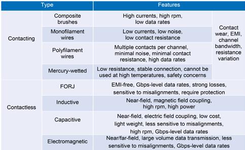
of industrial slip ring applications. However most of these conventional technologies are effective for data transmission only over short distances, which requires transceiver elements on a rotor and a stator to be in very close proximity to each other. Moreover, the fourth industrial revolution imposes strict requirements on configurability, reliability, and speed rates of data interfaces for slip ring applications that cannot always be met by conventional technologies existing today.
This article presents a novel solution based on a contactless technology that overcomes some critical limitations of other methods by relying on electromagnetic millimeter waves for transmission of data over longer distances in radiative near-field (Fresnel) and far-field regions. The proposed solution enables not only a compact and a cost-effective realization of an advanced microwave data interface for slip ring applications, but it can also be combined with conventional coupling elements of non-radiating rotary joints to achieve better performance at lower cost.
Millimeter Wave Data Interface Solution
Table 1. Classification of
Joints Based on Data Interface Coupling Technologies.
60 GHz Frequency Band: The emergence of low cost microwave component fabrication technologies has recently made them a commercial reality for broad market applications beyond the military space. In particular, millimeter wave 60 GHz technologies are receiving increased
attention from today’s broad market due to the unique advantages of this frequency band located in the upper region of the microwave spectrum. This global license-free and largely uncongested band offers a wide bandwidth of up to 9 GHz, which permits high data rates, provides short wavelengths that allow for a compact system design, and that has a high ratio of attenuation, which results in a low interference level. These benefits made 60 GHz technologies attractive for such applications as multigigabit WiGig networks (IEEE 802.11ad and the next-generation IEEE 802.11ay standards), wireless backhaul connectivity, and wireless transmission of high definition video (a proprietary WirelessHD/UltraGig standard).
In the industrial area, 60 GHz technologies are mostly used for millimeter wave radar sensors and lower data-rate telemetry links. However, rapid advancements in this domain make 60 GHz technologies very promising for the realization of high speed, ultralow latency data transmission in industrial subsystems. Integrated Data Interface Architecture: This article proposes a novel millimeter wave data interface solution utilizing 60 GHz frequency band for industrial slip ring applications. The key functional element of this solution is the Analog Devices 60 GHz integrated chipset comprised of the HMC6300 transmitter the HMC6301 receiver, which are schematically depicted in Figure 7 and Figure 8, respectively. This complete
silicon-germanium (SiGe) transceiver solution was originally optimized for the small cell backhaul market and it perfectly meets the data communication requirements of industrial slip ring applications. The chipset operates in the frequency range of 57 GHz to 64 GHz, and it can be tuned using either an integrated synthesizer in discrete frequency steps of 250 MHz, 500 MHz, or 540 MHz, or with an external LO signal to meet the specific modulation, coherency, and phase noise requirements of the target application.
The transceiver chipset supports a wide variety of modulation formats including on-off keying (OOK), FSK, MSK, and QAM with the maximum modulation bandwidth of 1.8 GHz. It offers a maximum output power of 15 dBm that can be monitored using an integrated detector. The chipset features flexible digital or analog IF/RF gain control, a low noise figure, and adjustable low-pass and high-pass baseband filters. One of the unique features making this solution ideal for ultralow latency industrial slip ring applications is an integrated AM detector in the receiver signal chain that can be utilized for demodulation of amplitude modulations such as OOK.
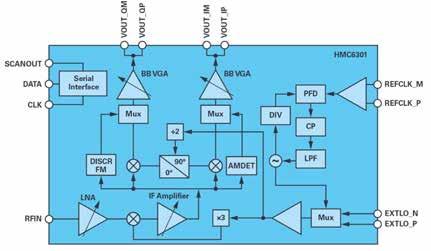
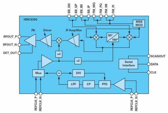
OOK is a very popular modulation method for control applications because it does not require the use of expensive and power-hungry high-speed data converters, thus enabling implementation of simple and low-cost communication solutions. Moreover, since OOK system architecture does not include complex modulation and demodulation stages, it offers low latency performance which is important for industrial real-time applications.
The Analog Devices’ transmitter HMC6300
and receiver HMC6301 integrated solutions both come in a small 4 mm × 6 mm BGA type package and offer an exclusive combination of features and performance capabilities to meet the most demanding requirements of modern high speed slip ring applications. In addition to the core transceiver elements, the complete concept of the full-duplex slip ring
distances of several tens of centimeters, which opens up a wide range of slip ring solutions for specific industrial scenarios.
Discrete Data Interface Architecture
Performance capabilities of the proposed integrated solution are sufficient for most industrial slip ring applications, but the
and basic custom blocks represented by passives, matching circuits, stub filters, bias tee, attenuators, and others (not all of them are shown in the figures).
This discrete proposal is based on a single detection system architecture. However, depending on the performance requirements can also help realize a superheterodyne architecture by downconverting the RF signal before the video detection stage.
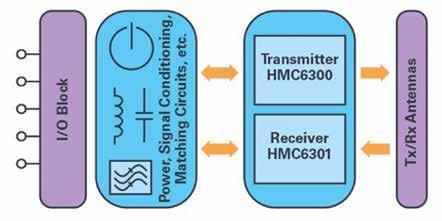

Conclusion
Industry 4.0 is driving change in many technologies and one such change is industrial communication. New application scenarios shaped by the fourth industrial revolution demand faster, more reliable, and more accurate ultralow latency data transmission between rotating parts of automation equipment operating in real time.
Analog Devices offers a broad range of high performance integrated and discrete RF and microwave components across the entire frequency spectrum that enable application specific designs for a contactless Gbps-level
data interface includes an antenna, power management, I/O blocks, and auxiliary signal conditioning components that can be chosen according to the requirements of a target use case. A high level block diagram of the complete 60 GHz full-duplex data interface solution concept is shown in Figure 9. This solution enables high speed, ultralow latency data transmission at speeds above 1 Gbps with a negligibly small bit error rate. Using a proper antenna design and gain settings, one can achieve reliable communication over
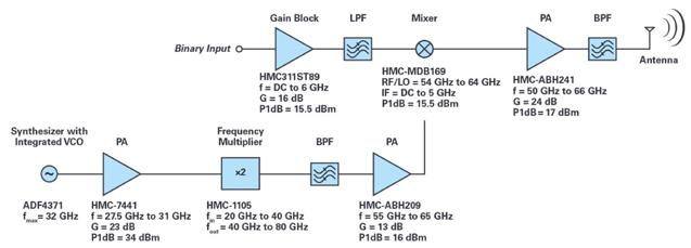
general trend toward customization of industrial components may require an implementation of even faster data interfaces supporting multigigabit speeds. In this case, it is possible to configure a customized solution to meet specific requirements using discrete components.
Figure 10 and Figure 11 show an example of a complete signal chain solution for a 60 GHz data interface supporting data rates above 5 Gbps. This OOK solution is realized with Analog Devices’ standard RF components
Figure 10. Complete signal chain solution for a 60 GHz transmitter (OOK modulator).
data transmission via rotary joints. This article proposed an integrated and a discrete data interface solution utilizing millimeter wave electromagnetic waves to transfer data between a rotor and a stator. The proposed solution offers not only high speed data transmission, ultralow latency, negligible bit error rate, strong interference attenuation, and maintenance free operation but it can also withstand higher misalignments and permits transmission over larger distances to enable a wide range of slip ring assemblies to meet the ever increasing needs of modern industrial applications.
Analog Devices offers Industry 4.0 partners deep industrial domain expertise and delivers next generation capabilities to develop faster and more cost-effectively advanced solutions for today’s factory infrastructure, with a future-ready pathway to what comes next.
Anton Patyuchenko, Field Applications Engineer. Analog Devices.
Visit Website
Industrial wireless connectors and the factory of the future
Phoenix Contact has a vision to leap manufacturing forward today with fast industrial wireless connectors. It found a collaborative partner with expertise in mmW (RF) technology to get to market faster to achieve its goal in Analog Devices. Here is an overview of their joint approach to next-generation wireless technology.
TODAY’S FACTORIES DEMAND FLEXIBLE manufacturing and wireless connectivity. Leading manufacturers need to react quickly to shifting customer needs, customization, and short product life cycles. They require interchangeable processes and equipment that can be reconfigured, modified, and replaced easily with maintenance-free connectors that reduce costs and downtime. However, much of the interchangeable equipment on factory floors still relies on traditional physical connectors that are subject to wear-and-tear and its effect on material costs and industrial productivity.
Imagine a factory where the physical connectors have disappeared; command instructions are sent wirelessly between robot subsystems to change out toolsets and setups quickly and efficiently, increasing production
speed while reducing costs. Is this the factory of some distant future? No, not according to Phoenix Contact, a market leader in industrial automation, interconnection, and interface solutions and renowned for its expertise in developing precision connectors.
Phoenix Contact has a vision to leap manufacturing forward today with fast industrial wireless connectors. However, it needed a collaborative partner with expertise in mmW (RF) technology to get to market faster to achieve its goal. The industrial innovator partnered with Analog Devices, known for its deep domain knowledge and technical expertise, to meet the challenge and co-develop wireless connectors featuring a compact, ultralow latency, protocolagnostic mmW solution. The next-generation technology will enable industrial wireless
connectors to be deployed on a large scale and open the door to a new and potentially lucrative industrial market niche.
At a glance
Here is an overview of the joint approach to this next-generation wireless technology.
Applications: Create wireless robot-totoolset connectors and solutions for industry, automotive, manufacturing, and equipment.
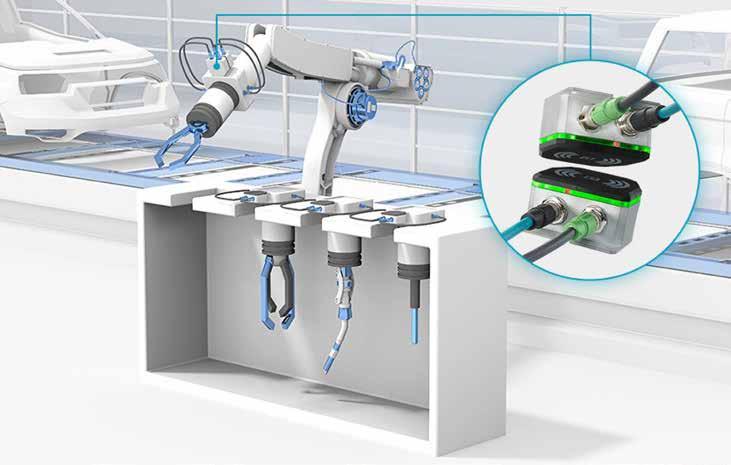
Challenges: Bring to market a wireless alternative for simultaneous power and data transmission as a compact solution delivering twice the power of competitors on the power side and wirelike/wireline performance on the data side.
Goal: Develop a unique, industrial solution that leaps manufacturing forward to a more flexible wireless system with the unique
ability to transfer both data and power simultaneously, while supporting all Ethernet protocols.
“Due to the high number of mating cycles during tool changes, the useful life of the connectors is significantly reduced because the contacts ‘burn off.’ They become dirty or bent during constant replacement,” said Benjamin Fiene, Product Marketing Communication Interfaces, Phoenix Contact. “This results in downtimes that cannot be predicted or scheduled. The cost for regular preventive maintenance intervals can quickly amount to seven figures.”
Physical connectors’ reliability and useable lifespan are limited in a manufacturing plant’s harsh operating environment and require regular maintenance. The plug and socket in a connector must be positioned precisely; otherwise, the delicate pins are quickly damaged. Connector misalignment may result in contact bending and downtime, requiring the immediate replacement of the entire connector assembly.

The challenge
Focused on increasing productivity and decreasing maintenance costs, Phoenix Contact identified high speed, wireless communication as the preferred solution for efficient data transfer from the robot to the tool. The biggest challenge was finding the right wireless technology. Ideally, the right wireless solution must transmit and receive faster than ever before to ensure real-time communication, include license-free
operation, be free of network interference, and support all standard industrial Ethernet protocols—all in a compact form factor. The proposed solution would not just be chip-level but a full system design challenge.
The collaboration
“We had the core concept on paper and knew how it should work,” said Frank Hakemeyer, Director Marketing and Development for Communication Interfaces, Phoenix Contact. “We might have purchased the chips from ADI and integrated them into a design, along with connecting antennas, but we felt that we would be operating outside of our core competency. We’re experts in Industrial Ethernet communication but not specialists in gigahertz RF. If we had decided to ramp up and do everything on our own, we would have needed more time. So, core competency and time to market were obviously big drivers in selecting a partner.”
Phoenix Contact turned to long-time partner ADI for its expertise across the RF spectrum. It asked ADI to identify the best technologies, co-design the full RF system, and deliver a complete customized data link wireless solution for its next-gen industrial wireless connectors.
Phoenix Contact first contacted ADI in August of 2017 about its vision and followed up by testing ADI standard transceiver chipset HMC6300/HMC6301.
“I first met with Phoenix Contact in April of 2018, at the largest industrial trade show in the world—the Hannover Messe,” said
Anton Patyuchenko, Staff Field Applications Engineer (FAE), ADI. “It mentioned it was considering using ADI’s original/standard V-band transceiver chipset for its industrial wireless connectors product.”
Developed initially for small cell backhaul applications, the HMC6300/HMC6301 included a unique combination of core functional features. These could enable the required ultralow latency wideband operation for timesensitive industrial systems that Phoenix Contact needed.
“In the course of our following technical discussions, I realized this was going to evolve into a full system design project,” said Anton. “Full system design requires that we engage differently and be brought in early in the process, not expecting to be told exactly what the customer needs. To create real value and engage in collaborative problem solving and exploration, we must thoroughly understand Phoenix Contact’s application. It’s not something just any semiconductor company can do.”
A succession of calls and in-person dialogues followed. On numerous occasions, the ADI team traveled to Phoenix Contact’s site, worked with its team, discussed ideas, performed measurements, and answered questions.
In August of 2019, after a year of planning, Phoenix Contact gave the go-ahead to develop the proposed technology. Apart from assigning a special FAE, ADI created a dedicated project team at technology group (TG) level, composed of a core team of six people from various
disciplines. Bi-weekly project calls ensued.
What emerged was a new industrial innovation—wireline performance without the wires.
An industrial wireless solution
Phoenix Contact’s complete wireless connector solution, named the NearFi coupler, comprises three main functional blocks represented by the data link, power link, and baseband electronics. They are all integrated into a compact design, enabling the final product's seamless adoption into numerous industrial applications. Analog Devices was responsible for developing the data link. Using Phoenix Contact’s NearFi Technology, the uplink and downlink signals provide simultaneous data exchange in both directions—i.e., full-duplex operation. The NearFi technology enables a 500 times faster response than 5G. In other words, it’s latency-free.
ADI developed a new product based on Phoenix Contact’s requirements,” said Chris O'Neill, Senior Product Marketing Director,
ADI. “It provided us with the key specifications of its target application. It also tested our prototypes, which helped us to identify any weak points and resolve them.”
Utilizing its RF expertise, ADI integrated the existing transceiver chipset (HMC6300/ HMC6301) and two dedicated antennae on a single laminate. To provide a complete custom solution to Phoenix Contact, ADI also developed a dedicated accompanying PCB for powering the laminate and interfacing its baseband part to the end equipment. The result is the ADMV9611 / ADMV9621—a complete 60 GHz data link solution and a piece of technology that enabled the new NearFi.

Advantages of data link solution
The data link provides a compact and costeffective data interconnect for the target application and achieves better performance at a lower cost. Other wireless solutions offer low latency communication; however, the ADI data link includes these significant advantages.
Immune to Electromagnetic Interference: Enables maintenance-free, high speed, and fully reliable data transmission with strong immunity to all electromagnetic interferences.
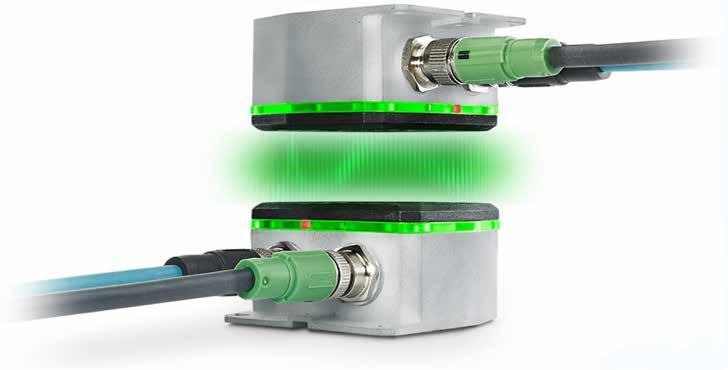
Immune to Contaminated Environments: Ensures reliable communication in dusty and contaminated industrial environments (which the solution can “see” through). This is a key advantage over alternative high speed wireless optical links that dust can obscure.
Handles Misalignments: Allows for uninterrupted operation even with high misalignment and at large separation/spacing of the transceiver pair.
Protocol Agnostic: Accepts a full range of Ethernet protocols as the design implementation is completely protocolagnostic.
Permits Coupler Co-Existence: Enables co-existence of several NearFi couplers and other 60 GHz applications in a very confined space.
Protocol agnostic advantage
Significant development is ongoing in the Industrial Ethernet world, including advances in Time Sensitive Networking. But changes won’t impact the effectiveness of ADI’s data link solution nor contribute to its obsolescence.
The 60 GHz wireless solution will always transmit in any new design or enhanced protocol, making its development an excellent long-term investment.
Technology report by Analog Devices. Visit Website
Carbon emission control through wireless IoT technology
AiR GUARD technology uses a cellular wireless device to enable monitoring and calculation of the carbon dioxide produced by manufacturing processes from field sites. It connects digital meters via Modbus RS-485, and data is transmitted in an encrypted format through the Azure Sphere chipset.
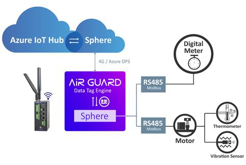
CARBON EMISSIONS IN THE CONSTRUCTION phase will gain significance over time. However, a real-time emissions monitoring tool, essential to help construction teams avoid excessive emissions, has not been introduced yet. Therefore, with a focus on enhancing monitoring of carbon emissions in this stage, EtherWAN proposes an IoT-based system framework that integrates a distributed sensor network to collect real-time emissions data.
In manufacturing systems, a process plan is the combination of diverse production processes and operations. Due to the different processes employed, even a small change in product process design can impact the environment in different ways. Additionally, the carbon emissions caused by auxiliary resource and energy consumption mainly stem from the electrical energy consumption of ancillary equipment in manufacturing plants, such as lighting, heating, and ventilation.
Once the quantitative values for each unit process and carbon emissions breakdown are determined, a range of improvement opportunities can be identified to monitor the resource and energy consumption during the entire process planning period. Each improvement opportunity has been linked to a positive effect on at least one previously identified carbon emission. When the factory or energy utility field site in a harsh environment becomes subject to carbon emission control, the next hot topic will be how industrial Ethernet systems take the CFV (Carbon Footprint Verification)
EtherWAN’s AiR GUARD is a cellular wireless device that enables the monitoring and calculation of the carbon dioxide produced by manufacturing processes from field sites through its specialized system. Furthermore, AiR GUARD connects the digital meters in the distribution board via the AiR GUARD Modbus RS-485. The data is transmitted in encrypted format through the Azure Sphere chipset. Then the received data from the AiR GUARD DPS will be sent to and stored in the AI system for analysis and calculation. All the analyzed outcomes will represent the data of the Carbon Footprint. The whole system can subsequently run the CFV management and control.
AiR GUARD plays an important role in this smarCFV system. It is a gateway that offers highly-reliable network connection

IoT-based system framework integrates a distributed sensor network to collect real-time emissions data.
through global 4G LTE, as well as operation at temperatures ranging from -40 to 75°C. AiR GUARD supports the MQTT protocol and OpenVPN, and is also equipped with the Microsoft Azure Sphere chipset, allowing for the combination of Azure cloud and cybersecurity protection. With its wireless features and combination with Azure Cloud tech, the entire CFV process can be easily set up without complex cabling and storage devices. In addition, the security and maintenance of network transmission can also be taken into consideration.
To avoid the worst climate impacts, global
greenhouse gas emissions must be slashed in half during the next decade, and reach net-zero early in the second half of the century. EtherWAN specializes in industrialgrade wired/wireless Ethernet connectivity devices, and is looking forward to its brand and products taking a role in the future drive towards net-zero for large enterprises. EtherWAN is demonstrating to industries worldwide the path to a greener planet.
Technology report by EtherWAN.
Visit Website
Efficient motion control for 5-axis fiber laser cutting system
EtherCAT and PC-based automation provides tools for a turnkey solution for auto manufacturer's fiber laser cutting system. Drive technologies from Beckhoff enable precise coordination of the up to five cutting axes, and ensure that the high-performance machine stays within tight tolerances.
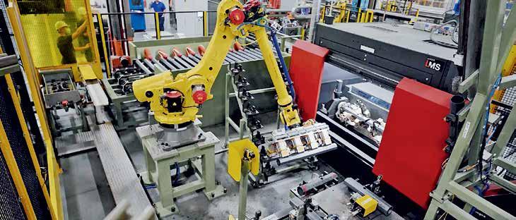
BOS INNOVATIONS IMPLEMENTED A L-MS FIBER laser cutting system as a turnkey solution for a leading automotive manufacturer. Drive technologies from Beckhoff enable precise coordination of the up to five cutting axes and ensure that the high-performance machine stays within tight tolerances. In addition, flexible PC-based control technology allows adaptation to different customer requirements.
As both a machine builder OEM and system integrator, BOS Innovations Inc. in Dorchester, Ontario, combines its strength in delivering turnkey machines with the ability to develop solutions to retrofit and tie into existing factory lines. “For 25 years, we have collaborated with major North American manufacturers to develop innovative, profitdriven solutions for automotive and other heavy industries,” says Ben Huigenbos, President of BOS. “We have developed core competencies in automated assembly, advanced robotics including welding, laser processing, coordinated motion technology, collaborative robots and quality inspection.”
These capabilities were clear in an implementation of the Laser-Motion System (L-MS) for a tier-1 automotive manufacturer. The L-MS is an advanced fiber laser cutting machine, equipped with a direct drive linear
motion system for precision CNC processes. This high-performance machine produces complex parts with tight tolerances by leveraging up to five axes of coordinated motion. “To make this L MS a truly turnkey system, we needed to add a robot to load and unload the parts and move them to stations for de-burring, vision inspection and marking,” says Steve Van Loon, Technology Manager – Laser and Motion Systems at BOS.
A laser focus on flexible and modular controls
To make sure the L-MS could support a bestof-both-worlds approach for many customers, BOS made flexibility and modularity top priorities in the initial design. In addition to a standard 1 kW fiber laser, the cutting head can accommodate up to two 0.5-6 kW laser sources or even welding (also remote welding). The machine has options for fume extraction equipment, automated scrap conveying, automatic doors and safety scanners for operator or robotic loading.
For processing, the parts can sit on a flat bed or use a trunnion system with additional servo axes to rotate the workpiece 360 degrees. By adding such a turntable, the loading time can occur in parallel with the
11.2022 industrial ethernet book
laser process. The flexibility even extends to footprint: The L-MS cell, a roughly 2-meter cube designed for 1,300-mm-long parts, can be expanded on all sides to accommodate workpieces of many sizes.
Providing this high degree of flexibility required robust yet above all adaptable controls and networking technologies that would allow the machine to integrate with other systems in the plant. Highly synchronized motor and drive technologies for the cutting axes were critical to ensure high part quality. Equally important was openness to enable real-time communication to the robot controller, de-burr components and vision system.
To address this, Steve Van Loon worked with Mechanical Designers Riley Tomiuck and Scott McCall on the design. The team determined that the system required higher performance than a traditional fieldbus and hardware PLC could deliver, so they turned to solutions from Beckhoff.
“Anytime we face demanding servo applications, we work with Beckhoff, so it just made sense for the L-MS,” Van Loon says. BOS first implemented Beckhoff automation technologies a decade ago on a large cardboard converting system that had about
50 motion axes, and other projects followed. Then in 2018, the company used Beckhoff technology to build the first iteration of the L-MS, which was designed to cut SUV running boards, and became a standard offering in its portfolio. For this project, the team worked closely with the local Beckhoff team, Automation Sales Engineer Dean Herron and Application Engineer Rui Zhang.
Motion control with EtherCAT makes the cut BOS implemented precision motion control on the L-MS using a variety of rotary servomotor and direct drive solutions with EtherCAT communication. The machine processes octagonal steel tube parts of variable wall thicknesses, cuts a 21.5-degree angle on one end of each piece and handles two variants with either six or 12 holes while maintaining tight tolerances.
The horizontal axes use Beckhoff AL2800 series Linear Motors, which deliver speeds up to 6 m/s and peak forces up to 4,500 N. “The X and Y axes have highly dynamic requirements in terms of acceleration, speed and accuracy, which called for linear motors,” Steve Van Loon says. The automotive manufacturer’s machine featured a Z axis and a trunnion system, which both used AM8000 Servomotors. With fast control technology, the AX5000 Servo Drives are ideal to support the dynamic application, and they permitted easy integration of a smaller, third-party motor to control the theta axis on the cutting head. One Cable Technology (OCT) in the servomotors and the servo drives reduces the cabling effort.
“Each device uses the EtherCAT function of distributed clocks to deliver exact synchronization and jitter of less than 1 µs, which is optimal for coordinated motion systems like the L-MS,” Dean Herron explains. The broad EtherCAT I/O portfolio from Beckhoff is open to support communication
to more than 30 protocols, and makes it easy to connect to other systems on the production line by adding an EtherNet/IP Bus Coupler, for example.
In addition to space-saving EtherCAT Couplers and I/O Terminals from Beckhoff, BOS also implemented TwinSAFE terminals for functional safety. This allows engineers to place safety technology directly within standard I/O segments, according to Rui Zhang: “BOS used the EL6900 TwinSAFE Logic terminal as a safety PLC on this machine. This approach allowed them to cut down the time and complexity otherwise required for hardwiring safety switches. All I/Os stay on the same rack or mount onto the machine with IP67 EtherCAT Box modules, and in addition, they could simply create safety logic in the standard TwinCAT engineering environment.”
TwinCAT allows engineers to select the programming languages they are most familiar with or that best suit the project. Here, they implemented TwinCAT PLC and CNC packages, and they appreciated the ability to use G-code, among other features. “TwinCAT Motion Designer was also very helpful for sizing the AM8000 series servomotors,” Steve Van Loon adds.
The control platform relies on a single Beckhoff CX2040 Embedded PC that features a quad-core Intel® Core™ i7 processor. A 15.6-inch CP2916 Control Panel provides multi-touch operator interface and high-
other things.
Delivering the best of both worlds
The complete L-MS system went live in the end user’s facility in late 2020. With fast controls and automated loading, the machine achieves a part-to-part cycle time of 40 s or less. “The L-MS easily runs at 2 m/s with 1.25 g acceleration, and it cuts holes with the highest precision that the customer says they have ever seen,” Steve Van Loon sums up. “That’s due to the controller speed and the fine tuning we accomplished with TwinCAT Scope. Using the software oscilloscope, we could see all parameters on the screen and collect data from each axis, including following error, acceleration and deceleration, to optimize the system.”
“Coordinated motion requires a lot of data to be passed between the servo drives and motion planner. EtherCAT is really the only fieldbus capable of handling that,” Van Loon explains. The finished laser cutting machine met all requirements of the automotive manufacturer, and BOS is already building additional units for other customers.
Special Supplement
CC-Link Automation Solutions
Learn about the technology and trends, applications and products shaping the newest generation of CC-Link automation solutions.
CC-Link continues focus on TSN networking solutions
CC-Link IE TSN is designed to address a number of engineering challenges as well as prepare companies for the new digital era of Connected Industries. Leveraging Time-Sensitive Networking and gigabit Industrial Ethernet, it enables factories to quickly adapt and evolve to incorporate promising new technologies.
TIME-SENSITIVE NETWORKING (TSN) IS AN ongoing focus for CC Link automation and control networking solutions.
For this Special Technology Update on CC Link, the Industrial Ethernet Book reached out to John Browett, General Manager of CLPA –Europe, to provide readers an update on this key Industrial Ethernet technology.
What key technical trends are driving the adoption of CC-Link automation, control and networking solutions?
The digital transformation of business, in line with Industry 4.0 principles, is driving companies to embrace digital technologies and smart solutions. These generate, share and analyse data to obtain actionable insights that can help optimise operations. This framework requires network convergence in order to deliver the necessary level of data visibility and availability.
The demand for enabling technologies that can support convergent communications is the main driver behind the adoption of the CLPA’s latest solution, CC-Link IE TSN. This is the first open gigabit industrial Ethernet that also offers Time-Sensitive Networking (TSN) functions.
Being the first organisation to launch a network technology with this functionality onto the market, our association has witnessed significant demand for CC-Link IE TSN and industrial automation products that are compatible with our solution. Moreover, thanks to a broad development ecosystem and an ever-growing range of certified devices, end users are already benefitting from highly convergent infrastructures.
What are the key technical advantages of automation systems that utilize CC-Link technology solutions?
Delivering convergence is the major outcome resulting from the adoption of a network technology with TSN functions, such as CC-Link IE TSN. This has a positive impact on a number of activities.
Automation systems that leverage CC-Link IE TSN can more easily merge operational technology (OT) and information technology (IT) traffic. This helps enhance the transparency, management and control of key industrial processes as required by the demands of Industry 4.0.
Furthermore, it leads to improved productivity, efficiency and product quality, as
automation components that are compatible with CC-Link IE TSN can help companies flag anomalies and improve troubleshooting, resulting in minimised downtime and lower maintenance costs.
In addition, it is possible to benefit from simplified network architectures, which can reduce capital expenses (CAPEX) and operational expenditure (OPEX) while streamlining the completion of industrial automation projects.
What are specific application areas that CC-Link solutions are targeting? How are these solutions contributing to IoT and enterprise connectivity?
The CLPA’s network technologies, such as CC-Link IE TSN, are aimed at ensuring seamless interconnectivity in industrial communications across a wide variety of manufacturing industries. Ultimately, they can support any discrete industrial automation application.
In particular, systems driven by CC-Link IE TSN and its predecessors have led to productivity improvements in automotive, food & beverage and logistics applications as well as in the manufacture of consumer

electronics, lithium-ion batteries, semiconductors and consumer packaged goods. Thanks to our range of technologies, companies in these areas have been reaping key operational benefits.
When looking at the IIoT and enterprise connectivity, CC-Link IE TSN represents a core element. In effect, it simplifies these strategies by enabling convergence of different types of system traffic, making it easier to extract key process data. This can help to improve process transparency and hence optimise operations.
In addition, our technologies can also help companies drive communications across different plants, marking the first step in the creation of connected supply chains and beyond.
What technology benefits are driving CC-Link adoption for automation and control networking in smart factory applications?
CC-Link IE TSN is an enabling automation networking technology designed to facilitate the creation of smart factories. Recent real-world applications include a leading manufacturer of 3D printers, Shashin Kagaku, who was able to introduce machines that offer a significant increase in performance while being simpler to build. By utilising CC-Link IE TSN, the key laser system is tightly integrated with a high precision motion control system, while reducing overall costs and time-tomarket. Ultimately, the resulting machine is ten times faster than previous models without TSN functions.
Orisol, a leading provider of automated systems for footwear production, is using CC-Link IE TSN to offer a unique assembly unit for heat activated adhesives that bond different shoe components. More precisely, this can deliver unprecedented speed and responsiveness as well as the connectivity required for Industry 4.0 applications.
CC-Link IE TSN has been used across the lithium-ion battery industry in China to advance key aspects of production. In particular, the technology enables better integration of the highly critical motion control processes with safety and general I/O control traffic while maintaining high performance operations.
What are the engineering challenges that the newest CC-Link systems and architectures are designed to address, and how is CC-Link evolving to provide more comprehensive solutions?
CC-Link IE TSN is designed to address a number of engineering challenges as well as prepare companies for the new digital era of Connected Industries. In addition to supporting this trend, it ensures that factory floors can quickly adapt and evolve to incorporate new promising technologies.
More precisely, our network solution can
help businesses move away from separate ‘islands of automation’ that can bottleneck the digital transformation of shop floors, with equipment that cannot share data. This inability has been limiting the setup of responsive and agile facilities, impacting productivity, efficiency and product quality as well as troubleshooting and maintenance. In addition, CC-Link IE TSN helps to remove the barriers that have traditionally been separating IT and OT in a safe and secure way. Besides, the use of CC-Link IE TSN eliminates
the need for multiple networks, which have historically been necessary to address the specific needs of motion control, safety and IT applications. These were complex, expensive and difficult to maintain.
Looking at the future, the CLPA is at the forefront of innovation, with its solutions supporting the technologies that are believed to be key for next-generation communications, namely wireless LAN (WLAN) and 5G. The CLPA has recently released guidelines to explain how this can be achieved.
CC-Link IE TSN connects with attendees at TSN/A Conference 2022
The TSN/A Conference has become an industry event for industrial automation and network technology specialists. The latest edition, which hosted nearly 300 participants, closed successfully for the CC-Link Partner Association (CLPA), which reported considerable interest in its Time-Sensitive Networking (TSN) solution, CC-Link IE TSN.
The TSN/A Conference has quickly risen to become a key technology event fostering discussions on future oriented communications based on TSN. This year marked the debut of the CLPA, whose key message was focused on how TSN is “here and now”.
This was backed up by presenting the latest real-world applications of the organisation’s CC-Link IE TSN technology at the event. CC-Link IE TSN is the first open gigabit industrial Ethernet with TSN functions, and the CLPA showcased its growing installed base across a variety of industry sectors. This was further reinforced with an overview of the benefits the technology delivered in each case.
Realising the benefits of TSN
During his presentation, John Browett, General Manager of CLPA – Europe, explained how the Instrumentation Technology & Economy Institute of the People's Republic of China (ITEI) which promotes best practices in manufacturing, was able to create a full-scale demonstration manufacturing system based on CC-Link IE TSN to illustrate the benefits TSN can deliver. The facility features a converged network architecture, which handles transfer of data from machining, assembly and logistics areas as well as CNC condition monitoring and tool protection systems. This allowed ITEI to highlight the reduction of complexity while increasing transparency and productivity.
Similarly, CC-Link IE TSN allowed a leading manufacturer of additive manufacturing systems, Shashin Kagaku, to launch new, value-adding 3D printing machines. These offer a significant increase in performance while featuring a simpler, leaner and cost-effective design. In particular, the key laser system within the unit is tightly integrated with a high precision motion control system that makes the machine ten times faster than previous models without TSN functions.
In addition, John Browett explained how CC-Link IE TSN compatible devices have been utilised by Orisol, a leading provider of automated systems for footwear production. The company’s latest assembly unit for heat activated bonding of shoe components offers high speed and responsiveness. In addition, Orisol can deliver the level ofconnectivity required for Industry 4.0 applications.
Finally, the presentation covered how companies in the Chinese lithium-ion battery industry have been using CC-Link IE TSN to bring production to the next level. Highly critical motion control processes related to electrode coating and cell assembly are better integrated with safety and general I/O control traffic while maintaining high performance operations.
Enabling the digital transformation of business
Anyone keen to learn more about TSN and CLPA’s network technology support for key industries but couldn’t attend the 2022’s TSN/A Conference will greatly benefit from a recording made of the presentation.
This can be viewed on YouTube at https://youtu.be/U8k6VlvFSBE. The organisation’s latest white paper. “Delivering TSN’s benefits to manufacturing” further backs up this material and is available to download for free from https://eu.cc-link.org/en/ campaign/2022/tsnwp.
11.2022 industrial ethernet book
Creating competitive machines with Time-Sensitive Networking
CC-Link IE TSN is designed to address a number of engineering challenges as well as prepare companies for the new digital era of Connected Industries. Leveraging Time-Sensitive Networking and gigabit Industrial Ethernet, it enables factories to quickly adapt and evolve to incorporate new promising technologies.
AUTOMATION DEVICE VENDORS NEED TO KEEP pace with the latest technologies more than anyone else in order to deliver competitive products that address market requirements. As an enabler for Industry 4.0 applications, Time-Sensitive Networking (TSN) is quickly becoming a must-have to deliver state-ofthe-art connectivity.
TSN is a major development in industrial Ethernet communications with tremendous potential for end users and device vendors interested in futureproofing their facilities and solutions, respectively. In effect, this technology is key to creating automation networks that can handle multiple types of traffic while addressing the need for deterministic data transfer, i.e., for control communications on the shop floor. The level of reliable convergence created offers several benefits.
Firstly, the possibility to convey different traffic types onto a single pair of wires reduces network costs and complexity, as it is possible to rely on a simplified architecture. This, in turn, can streamline the addition or modification of nodes as well as maintenance and troubleshooting activities.
Secondly, these capabilities support data transparency and availability across the enterprise to assist decision-making and management. In particular, it is possible
to merge information technology (IT) and operational technology (OT) in order to create responsive Industrial Internet of Things (IIoT) frameworks that are at the core of Industry 4.0 applications.
When looking at automation devices compatible with TSN, these can effectively transfer to and receive key information from any other element within the network, delivering next-level flexibility and responsiveness to maintain peak productivity. Therefore, they will be able to outperform existing solutions.
Recognizing the commercial value of TSN
These considerable advantages have not gone unnoticed by businesses and machine builders in a variety of sectors, which are beginning to implement key systems that feature TSN functions to succeed in their digital transformation. In particular, a considerable number of projects are being carried out in fast-paced sectors, such as the semiconductor and automotive industries. Similarly, lithium battery manufacturers and leading players in packaging, food, and beverage as well as consumer packaged goods are driving the wave of TSN adoption.
By embedding TSN in their automation devices, vendors can therefore meet the

market requests for highly connected, datadriven solutions. This means that companies can provide end users with precisely the tools they are looking for, as there is a clear shift in the industry towards this technology.
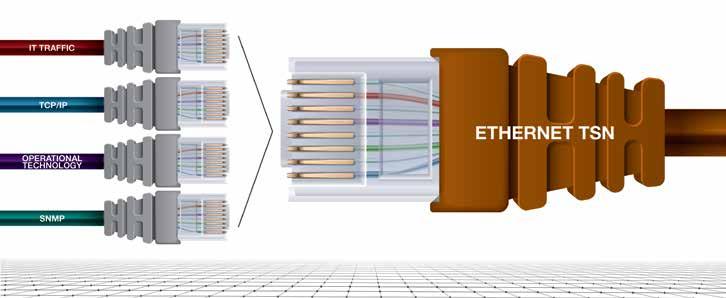
To successfully tap into this market, it is important for product vendors to act quickly in order to serve this growing and partially unaddressed segment. By doing so, companies can establish their role in the industry as well as face less competition, benefitting from better profit margins.
So, what does a company convinced of the
benefits of TSN and wanting to adopt it do now? The answer is to look for a technology that supports TSN currently while providing the necessary application functionality, such as safety and motion control. It’s been almost four years since CLPA introduced CC-Link IE TSN, which involved using the established open industrial Ethernet solution of CC-Link IE and adding TSN compatibility to it. What resulted? The world’s first open industrial Ethernet technology to combine gigabit bandwidth with TSN.
This technology provides the gateway to the future of open industrial Ethernet. End users, machine builders, and vendors can now adopt a proven technology in their respective products and projects. The ecosystem of development options that are available to vendors who want to offer TSN-certified products is broad and flexible.
Compatible solutions from leading vendors are already available. For device vendors, developing TSN-compatible products now will shape the future of automation. TSN helps to deliver the promise of Industry 4.0 in three key ways:

Performance: CC-Link IE TSN is the only open industrial Ethernet currently available to combine gigabit bandwidth with TSN to provide the highest productivity via maximum bandwidth availability.
Connectivity: Being an open technology maximizes the freedom of choice for end users and machine builders, while also providing implementation flexibility for vendors. TSN takes openness one step further by offering the ability to combine TSN traffic with that of other protocols.
Intelligence: Reduce engineering time and maximize uptime with a range of features intended to simplify system design and maintenance.
The tools at hand
To add TSN functions to their solutions, device vendors can rely on TSN technology to offer combined deterministic and convergent performance. In the case of CC-Link IE TSN, it also features a broad development ecosystem to help automation specialists create advanced TSN-compatible solutions in line with their goals.
With a cascade of industry players in the automation sectors, leveraging TSN to deliver innovative products, the technology is gaining momentum. As more and more groundbreaking devices are available to test and utilize, end users are showing ever-increasing interest. Therefore, device vendors offering their solutions can now rapidly grow their business and competitiveness with a reliable, future-oriented industrial Ethernet that is accepted globally.
The strategy with respect to technologies like Ethernet TSN is to create a set of services,
to be used by all the other industrial Ethernet protocol organizations. Collaboration is required, specifically making their protocols leverage the new services in a way to deliver co-existence. An Ethernet standard alone -- delivering services for traffic shaping, prioritization, and scheduling -- cannot, on its own, enforce compliance. In addition to developing the standards, owning organizations have a process in place to facilitate companies developing and releasing products that properly leverage their new services. Certification and validation are necessary to ensure that users of standards are releasing products that are compatible in a multi-vendor community.
TIACC (TSN Industrial Automation Conformance Collaboration) is a unique and important initiative that clearly demonstrates the value proposition of Ethernet TSN technology through the participation of competing organizations. The leading industrial Ethernet organizations – CC-Link Partner Association, ODVA, OPC Foundation, PROFINET International and AVNU, are working together to make sure that the solutions from their respective organizations are validated and tested together so that end customers may make use of a blended TSN architecture. The organization is focused on developing the necessary test specifications to ensure the co-existence of industry protocols.
Overall, the industrial automation and electronic design market is trending towards interoperability. The TIACC collaboration will accelerate that trend. Digital manufacturing and Industry 4.0 need data to be able to move freely in a real-time and predictable manner. End users want the ability to have plug-and-
11.2022 industrial ethernet book
play interoperability and to have all these different networks and devices coexisting and working together. The greatest ROI value comes from transforming data into useful information. The more data – the better the information, and this is the key strategy of digital transformation.
Multi-dimensional protocols are needed to successfully implement innovative industrial Ethernet systems that leverage TSN, particularly to support demanding automation applications on the factory floor. These protocols need to support deterministic performance, ad-hoc data transfers as well as support device management and troubleshooting. CC-Link IE TSN is characterized by a strong backbone for safety communications as well as I/O and motion control. In effect, it relies on a proven industrial Ethernet protocol that was specifically developed to run these applications. This has been widely used in industrial settings around the world, particularly in Asia where the CC-Link IE and its fieldbus counterpart, CC-Link, are the de facto standards.
There are over 100 industrial automation products today that have TSN capabilities, including those from Mitsubishi Electric, Moxa, Belden, Phoenix Contact, Weidmueller — and this will certainly grow due to the enhanced performance that TSN provides. TSN allows a broad spectrum of device integration operations from both a hardware and software perspective.
How all protocols fail at data access interoperability
If you are interested in being challenged to fundamentally rethink how an enterprise-wide Data Access system should be architected, you have come to the right place. Matthew Parris, Senior Manager, Advanced Manufacturing – Test Systems for GE Appliances, shares his experiences and ideas for moving ahead.
NOTE FROM THE AUTHOR - I HAVE BAD NEWS: most industrial interoperability discussions include empty promises. However, I also have good news: the reason for the empty promises is not a technological problem. Even better news: interoperability is a problem that has already been solved once, and those concepts can be reused to solve today's problems.
If you are looking for a short article that will gloss over vague concepts using a few buzzwords sprinkled throughout, save your time by not reading this article. However, if you are interested in being challenged to fundamentally rethink how an enterprise-wide Data Access system should be architected, you have come to the right place. This article is written for those disappointed by the lack of available products that enable data access interoperability within the manufacturing industry. It is mainly targeted to those interested in turning the paradigm upsidedown to move the industry in the right direction.
When authoring this article, I considered whether the content should be delivered as a series of small and manageable articles or whether it should be a comprehensive and cohesive tome. Whereas our modern sensibilities prefer the convenience of fast food with small portions individually wrapped and delivered immediately, I am presenting you with a ribeye steak.
So, if you only have the time for fast food or your pallet will not appreciate a steak, do not read this article; its length will not disappoint a publication with "Book" in its name. When you are ready, however, schedule an hour, pour a pint of New Castle or a stein of Märzen, and have a ribeye steak. Take the time to digest, then decide what your role will be to improve the manufacturing industry.
IIoT: Real-time Data Access
Most take for granted how many mechanisms must work correctly to receive information through computer networks. However, supplying information in scalable ways through equipment across the globe is only possible through interoperability, primarily achieved through a commercial market coalesced around a few well-known standards. As various parts of a technology stack become standardized through commercial products,
the quicker "things" can be connected and integrated at scale.
Take the familiar example of web browsing, where a modem is a gateway for the internet. After purchasing a PC, it is brought home, and the benefits of standardization are immediate. First, the out-of-the-box PC likely has an Ethernet port; if not, one can be readily added from any third-party company. After connecting the PC to the internet modem, it gets an IP address through the Dynamic Host Configuration Protocol (DHCP) and discovers its network gateway. Then it discovers what its Domain Name System (DNS) server is and starts accessing a broad range of information from across the globe. All these mechanisms are automatically activated through a single gateway; for most users, it is a technology equivalent to magic.
Like the plug-and-play experience of web browsing, manufacturing seeks to automate the integration of equipment and applications, so instead of humans connecting things manually, they invest their time towards complex challenges. However, anyone participating in Industry 4.0 knows
that standardization is still ongoing. In many ways, it is only beginning, and products within the marketplace have yet to pick a standard set of technologies.
The Industrial Internet of Things (IIoT) includes many services and functions. Still, the focus of this article is Real-time Data Access, also often referred to as equipment or process telemetry. This type of data is typically categorized as time-series data, non-transactional, in the form of truefalse, numbers, or text. Visualizing or measuring what is occurring on the plant floor is usually the first baby step in digital transformation. This article focuses on the most straightforward use case of IIoT—Data Access—to demonstrate the significance of the interoperability gap. IIoT presents an enormous challenge for manufacturers, and even attempting to tackle this aspect of accessing data from the plant floor is enough to halt some Digital Transformation initiatives. If the amount of market confusion on just this one IIoT topic is any indication, then a long road awaits manufacturers embarking on their journey.
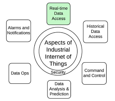 SOURCE: MATTHEW PARRIS
The content below first outlines a framework in which data access technologies can be assessed. Then, it compares existing Data Access technologies from the perspective of this new Data Access framework. Later, client-server applications are contrasted with publish-subscribe applications when deploying an enterprise-wide communication infrastructure. Finally, this article identifies the most significant standardization gap in data access, halting efforts of manufacturers to deploy interoperable systems.
Industry 3.0: Decoupling Physical Location
Forty years ago, battles raged regarding which low-level protocols should dominate the market, such as X-25, FrameRelay, Thicknet, ARCNET, Token Ring, Fiber Distributed Data Interface (FDDI), and Ethernet. These technologies sought to ease the burden of connecting consumer applications to data sources. Unfortunately, many times, connectivity was constrained by the physical locations of each.
As more technologies and protocols were developed, the seven-layer Open Systems Interconnection (OSI) Model was published in 1984 to coordinate interoperability between disparate systems. Today's network architectures still reference the OSI model by labeling network equipment as Layer-2 or Layer-3. The OSI model, however, is less relevant than it once was; the protocols used within today's network stacks fit outside the seven-layer model--either a protocol spans multiple layers, or one layer implements numerous protocols. Competing with OSI, the TCP Model reduced the number of layers to four and used specific protocols at three of the layers. This specificity focused the market on producing products that would interoperate out of the box.

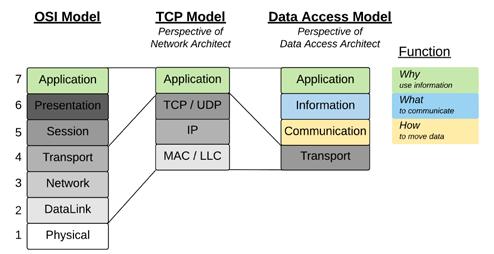
While the TCP Model adds complication and abstraction compared to applications that access devices directly through physical interfaces, embedded protocol stacks and operating systems have shielded applications from this complexity. Furthermore, given the ubiquity of the TCP Model, applications have the benefit of assuming standard connectivity methods regardless of each device's location. When developing applications before the TCP Model, the market expended energy on learning about all the possible connectivity options and optimizing the best technology for a given solution. After TCP Model became the standard, the market refocused its energies on developing standard application protocols such as HTTP, Modbus, and OPC Classic on top of a consistent network infrastructure. The efficacy of providing the commercial market with a narrow and capable technology stack is undoubtedly proven by today's internet ecosystem, comprised of many Original
Equipment Manufacturers (OEMs) and network architects who design and manage the many components comprising the worldwide web. This global network is only possible with the market coalescing around specific standards.
The Data Access Model Explained
While powering worldwide connectivity, the TCP Model does not detail communication protocols or information encodings required for consumers and producers. IIoT initiatives are not primarily concerned with the physical network connections, how the LANs are segmented, which routes must be taken, or how to maintain connectivity reliability; all these capabilities are assumed to exist already. The discussions regarding IIoT architectures primarily target the only layer not standardized by the TCP Model: its Application Layer. In place of the TCP Model, OEMs, system integrators, and end users need a new framework to improve the discourse regarding product capability and Data Access strategies-- a model that reveals the interoperability intricacies between consumers
and producers.
Just as the TCP Model compresses all the IIoT efforts into a single Application Layer, a new framework, The Data Access Model, compresses all the network infrastructure into a single Transport Layer.
A Communication Layer sits above the Transport Layer and handles how data from TCP/UDP moves between producers and consumers. An Information Layer above the Communication Layer specifies the information formats. Finally, on top of the Information Layer sits the Application Layer, which is the business justification for embarking on the IIoT journey in the first place.
The simplified view of the Data Access Model shown above must be expanded into more layers to expose how consumers and producers need standard definitions to eliminate custom integrations. For example, the Communication Layer defines the communication protocol, but those having integrated systems know that more than the protocol is needed for interoperability. In addition, there are many ways a protocol can be used, so a
11.2022 industrial ethernet book
Mappings layer is necessary to standardize how to use a given communication protocol by defining what functions are within the scope of the application and what protocol options are declared mandatory. Similarly, the Information Layer must be expanded to detail the many ways to represent data through various encoding schemes, values, and object definitions.
The diagram below shows typical Data Access applications within the model to understand how this model is applied in the real world. For the web browser application, Communication Layer is handled by the Hypertext Transfer Protocol (HTTP), Information Layer is implemented by Hypertext Markup Language (HTML) and encoded by ASCII Text. The tech stack here is narrow and well-defined, eliminating multiple options within each layer where no custom definitions exist,

allowing customization with the content itself. This standard has enabled wide-scale interoperability for the internet by reducing the number of protocols engineers must learn and eliminating code that would have been written had more protocols been allowed as options.
A RESTful Application Programming Interface (API) is another standard method of exchanging information and was designed for flexibility. Compared to Web Browsing, the extra flexibility complicates interoperability between consumers and producers. While HTTP is a widespread communication protocol and is primarily assumed to be used by producers, many choices remain for the levels above, such as encoding or value types. To achieve interoperability, one of two scenarios must take place. First, consumer applications must be developed to accommodate all possible
encoding and value schemes. Alternatively, an integrator must determine what encoding scheme a producer uses and then closely evaluate the capabilities of the target consumer application and, if necessary, develop a translation service to enable compatibility. Additionally, while APIs only define a single data type -- called a "Resource" -- the Object Definition is completely custom. Undefined objects favor flexibility at the expense of higher integration efforts learning about the custom model, and then determining how best to map it to whatever object definition already exists within the enterprise.
How OPC UA and MQTT Prevent Interoperability
One of the many goals of Industry 4.0 is to eliminate the integration cost when incorporating new producers or consumers within the enterprise. Simplifying integration is achieved primarily through products implementing a handful of well-known standards at the Communication and Information layers. OEMs solving this problem may advertise their products as supporting "OPC UA" or MQTT." Similarly, end users may specify equipment to comply with "MQTT" or "OPC UA." Are these two terms, however, enough to achieve interoperability?
MQTT has become a popular choice for systems implementing "provide data once; distribute everywhere" architectures. Defined in 1999 towards the tail-end of the protocol wars, MQTT defined a lightweight alternative to traditional client-server connectivity for distributed oil wells constrained by expensive satellite bandwidth. MQTT reduces bandwidth by moving from a conventional poll-response behavior to an event-based behavior where a consumer waits for changed data. In addition, defining devices and equipment with MQTT has reduced the cost of integration since the consumer application can have a single connection regardless of the number of
producers and, through wildcard subscriptions, can automatically discover new data as it appears. While invented as an Industrial Protocol, it remained largely unknown until around 2011, when IT-based companies began learning its inherent scalability and deployed the technology within popular, consumerfacing applications. Ironically, the protocol's popularity within the IT space was needed to provide a compelling reason to begin deploying an OT protocol within the plant floor.
The OPC Foundation released its first OPC UA specification in 2006, which featured Data Access among many other connectivity functions. Products began implementing OPC UA to transform existing connections with benefits such as enabling non-Windows devices, browsable address spaces with standard datatype definitions, and long-polling mechanisms with dead-band filter criteria. OPC UA became popular among manufacturers because it upgraded existing client-server paradigms established from the original 1996 OPC specification. As publish-subscribe protocols increased in popularity, PubSub connectivity was added to the specification in 2018, including broker-less protocols (Ethernet and UDP) and brokered protocols (AMQP and MQTT). Continuing its goal of interoperability, the OPC Foundation defined standard object types through companion specifications, each of which utilizes the core data definitions to construct standard object definitions.

Regarding interoperability, the terms "OPC UA" and "MQTT" are undefined and originate from opposite sides of the same coin. As seen in the figure above, specifying MQTT for equipment only defines the base communication protocol, leaving all the remaining stack undefined, which levies a heavy burden for integrating consumer applications. Integration hurdles for the consumer include learning the topic paths implemented by the producer and determining whether an application can monitor the producer's health through the Last Will Testament function. Also, a challenge is choosing which QoS level to use, whether producers are publishing on fixed time intervals or only on changed data, and many others. Even more daunting to integrators is that MQTT has no definition of the transmitted data, so the consumer application is forced to accommodate whatever the device selected regarding the encoding scheme, data types, and object definitions. Specifying "MQTT" is not enough if the goal is interoperability.

Whereas "MQTT" is undefined above the Communication Protocol layer in the Data Access Model, OPC UA has achieved standardization at every level of the Data Access Model. While definitions at each layer are an achievement matched by no other technology, the portfolio of specifications includes many choices at each level of the model. Given the plethora of communication protocols, encoding schemes, data types, and
object definitions, simply connecting an OPC UA consumer to an OPC UA producer does not guarantee interoperability, as each application may select different options up the stack. An integrator must closely evaluate what options at each layer are implemented by the producer device and ensure it matches the capabilities of the consumer application. Or conversely, the integrator will know the consumer application capabilities and be forced to limit the scope of OPC UA products that he can utilize. Specifying "OPC UA" is not enough if the goal is interoperability.
Consumer-centric Integration
Technology is only as good as the products that implement it. Unfortunately, when integrators and end users evaluate what Data Access technologies will be used within their enterprise, many prioritize the available technologies within devices and applications that produce data without considering the consumer applications' capabilities. This producer-centric approach will lead to unforeseen costs or, worst-case, a failed IIoT deployment.
For example, before buying HD DVDs or Blu-ray Discs, one should first determine if the video player must be built or if the player can be purchased; the answer to this simple question determines which disc will be selected from the shelf. Therefore, a system architect should begin by considering the
applications that receive data and exist in the market and then evaluate them based on their implemented technologies that minimize the cost of integrating devices at scale. After a Data Access technology demonstrates business value through consumer applications, an end-user will inevitably demand that future producer devices and applications comply with those selected technologies.
Consider a simple user story that has existed since the start of Industry 3.0: "As a data analyst of a multi-facility enterprise, I want an interface to access data originating from any facility so my single application can solve many different problems." What is the industry standard for enabling this single application to connect to many data sources within the enterprise? Without a standard data access interface, system integrators will pursue the path of least resistance by continuing to provide end-users with custom communication and custom information definitions.
Industry 4.0: Decoupling Consumers from Producers
The most outstanding achievement of the TCP Model is connecting devices regardless of their location, all while allowing applications to maintain their existing connectivity strategies. However, over the past forty years, the unchanged connectivity strategy has been the problem facing most manufacturers embarking on their Industry 4.0 journey. The figure below highlights two common communication strategies: (1) "Point-to-Point," which has been present since the beginning of Industry 3.0, and (2) "Point-to-Infrastructure," which has gained popularity within Industry 4.0.
Within "Point-to-Point" architectures, the number of connections a consumer must
initiate is directly correlated to the number of producers in the system. The number of producers also dictates the number of different protocols and custom parsing functions that must be engineered on the consumer's side. As a result, the Point-to-Point model becomes unsustainable as the number of producers increases and the number of implemented protocols increases.
Enterprise systems have been challenged by the number of protocols required when collecting information from all plant-floor devices. The burden is too significant for applications to communicate with any protocol across all devices. There have been efforts to eliminate this burden by commonizing the plethora of protocols, but product adoption has been half-hearted. Rather than prioritize standardized protocols alone, automation OEMs continue to innovate atop native Fieldbus technologies such as EtherCAT, PROFINET, and EtherNet/IP. Nearly all devices continue to support Modbus/TCP for exchanging data, and some have added IO-Link. A few devices have progressed to include OPC UA Servers, but even high-volume OEMs that are members of the OPC Foundation still omit OPC UA Servers. Some integrators and end users await the latest device specification, OPC UA FX, expecting that it will result in greater market adoption. In contrast, others seriously doubt whether a standard protocol is even possible at the industrial device level.
While standards organizations continue convincing OEMs to standardize device connectivity technologies, a critical component of the Data Access architecture continues to be the Device Gateway. Whereas IT systems can be assumed to contain Ethernet interfaces, Operational Technology
(OT) systems are not as homogenous. Many devices on the plant floor have physical interfaces that are not Ethernet, such as RS-232, RS-485, CAN, and others. Device Gateways protect a consumer application from the number of physical interfaces and device protocols while simultaneously providing consumer applications a single point of connectivity regardless of the number of devices. Additionally, it reduces the number of connections a device must service from all the consumers in the enterprise. As Device Gateways and consumer applications proliferate throughout the enterprise, however, Device Gateways then become the bottleneck for scalability within point-to-point connectivity.
Building Communication Infrastructure
In today's market, the consumer application often resides within a cloud service provider, which favors scalable publish-subscribe protocols. If pub-sub is the most scalable strategy within cloud applications, how far down the manufacturing enterprise should those scalable technologies be leveraged?
Conversely, the factory floor uses clientserver protocols, which specialize in fast communication among static devices. If client-server is appropriate on the factory floor, how far up the manufacturing enterprise does client-server stop making sense? To minimize integration costs as the number of devices increases, an enterprise should expand to its lower levels the same technologies favored by cloud platforms. One of the most important architectural decisions is whether to use client-server or publish-subscribe when connecting to a cloud platform.
Consumer applications within cloud platforms commonly support publishsubscribe, allowing devices within an enterprise to initiate the connection to the cloud platform. End-user firewalls prefer this to a cloud application creating a connection through an open, inbound port. However, the challenge of opening inbound ports for OPC UA client-server architectures has been solved through the "Reverse Connect" function. This function allows a server/device to initiate a TCP connection to the client/consumer so the client can then have an open path through the firewall to begin the standard OPC UA application-level connection. Since "Reverse Connect" is a unique feature requiring reading producer devices' fine print to determine its compatibility, system integrators will favor publish-subscribe architectures that inherently enable connectivity to cloud platforms.
In addition to connectivity benefits, publish-subscribe inherently allows consumer applications to discover the presence of new devices automatically. OPC UA client-server architectures solve the discoverability problem through Aggregation Servers that federate data from many OPC UA servers. Consumer applications connect to the Aggregation Server, and devices implementing "Reverse Connect" can initiate connections to the Aggregation Server through its well-known address. The consumer application, which is already subscribed to the Aggregation Server's address space, can automatically access any newly added device.
Another OPC UA discovery architecture is to deploy a Global Discovery Server where devices register their presence to the server. The Aggregation Server can be a client and use that registration to initiate a connection to the device. The challenge for the OPC UA ecosystem is to define a microbrand of products, each of which implements OPC UA
client-server functions of "Reverse Connect" or "Discovery Server" for all consumers and producers. Whereas OPC UA products can automatically discover devices within a network, lack of standardization ironically challenges integrators to locate these products within the commercial market. Integrators can readily find "MQTT" applications but finding available "OPC UA Aggregation Server including Reverse Connect or Discovery Server" compatible with "OPC UA client applications including Reverse Connect or Discovery Server" is undoubtedly more challenging.
Another capability of applications within cloud platforms is allowing multiple instances to be clustered together, either to increase system availability or to increase throughput through parallelism. Most enterprise-level MQTT brokers inherently include cluster functions to satisfy cloud-based applications' availability or scalability needs. As a result, these application instances can be scaled on demand, allowing end users to optimize infrastructure costs using only the necessary computing resources. However, OPC UA client-server instances are more static and monolithic due to the focus on industrial and manufacturing applications. Therefore, supporting clustering functions would be considered the exception, not the rule.
Because MQTT is agnostic regarding the payload, it is used by many industries, from large IT companies to automotive companies and IoT platforms. Exposing an MQTT broker to many use cases worldwide equates to identifying more issues and requesting more features, which translates to becoming a much more resilient product overall. OPC UA clientserver aggregation applications are typically limited to industrial or manufacturing use cases which prolongs the timeline of achieving an equivalent level of application hardening.
Combining Scalability with Interoperability
Many applications within the Internet of Things (IoT) space have leveraged MQTT as a lightweight method to publish data to any number of consumers. However, while MQTT enables scalability, it cannot facilitate interoperability on its own. The OPC Foundation, on the other hand, understands the integration challenges when only the Communication Layer is specified, and so they have standardized the entire stack from communication through information. Going further, the OPC Foundation advises that the Information Layer is of primary importance over the Communication Layer by saying, "it's not about the protocol; it's about the payload." The Information Layer is shown to be OPC UA's main value proposition, given that it dedicates over 4000 pages to specify information definitions, dwarfing its communication definitions at less than 300 pages.
Solving the lack of information interoperability over MQTT, the Sparkplug standard was created in 2015 to define explicitly (1) protocol mappings, (2) an encoding scheme, (3) common data types, and (4) a means for custom object structures. Sparkplug began as an unknown proprietary definition from Arcom/Eurotech to assist internal integrations over MQTT. Within a year, Cirrus Link used the technology to develop various third-party modules for Ignition, a popular SCADA/MES platform.
Ignition's MQTT Engine module established a simple and obvious use case for Data Access interoperability. Sparkplug producers from any number of vendors publish information to a standard MQTT broker. The information, then, becomes immediately available and enumerated as tags and User Defined Types (UDT) within Ignition's internal tag structure.
11.2022 industrial ethernet book
However, the most impressive aspect of this function is that the discoverability of newly connected Sparkplug devices occurs automatically without input from an end user or integrator. In 2019, the Eclipse Foundation, an open-source organization, took ownership of the Sparkplug specification. Its popularity continues to increase due to Ignition allowing anyone to evaluate its platform through free and fully functional trial downloads, including a free Maker Edition that any hobbyist can use. Whereas Sparkplug built its stack from the bottom up to define information over MQTT for interoperability, the OPC Foundation worked from the top down to specify publish-subscribe functionality for scalability. OPC UA Working Groups began developing standards to extend its existing information definitions through other use cases such as firewall traversal, controller-to-controller communication, controller-to-cloud communication, or connecting producers to consumers at scale through message brokers. Finally, in 2018, the OPC Foundation released Part 14: PubSub specification, where MQTT has become the most popular of its four communication protocols, primarily due to the market's previous familiarity with MQTT from Raspberry
Pi applications, home automation projects, or other IoT applications. Additionally, the UA-IIoT-StarterKit released in May 2021 features MQTT only, and recent OPC webinars primarily discuss "OPC UA over MQTT" when referring to PubSub architectures.
Challenges of Data Access Protocols
Products able to consume Sparkplug information out-of-the-box, such as HighByte Intelligence Hub, Canary Historian, Cogent DataHub, OPC Router, and Sorba.ai can dynamically receive information directly from any number of Sparkplug producers. Then they immediately begin using that information by ingesting the producer's data structures within their applications as native variables and object definitions.
Troubleshooting tools such as MQTT.fx and Wireshark include Sparkplug decoders so that the data can be reviewed across the wire. In addition to SCADA products like Ignition and FrameworX, cloud service providers such as Amazon Web Services, Azure, and Google Manufacturing Platform can receive Sparkplug data and translate it to their native cloud ecosystems through IoT Bridge for SiteWise, IoT Bridge for Azure, and the Manufacturing
Connect Platform. These applications make it as simple to receive structured data: (1) specify the IP address of the MQTT Broker along with appropriate credentials, (2) determine what data group is of interest, and (3) use the application to consume the data.
However, the applications listed above are monolithic and designed for use cases that should receive all data from most or all producers. As a result, Sparkplug begins to show its limitations when deploying it across an enterprise and integrating applications that are smaller in scope. For example, applications that only want a single, slowchanging variable must wade through all data from a producer node, including fast-changing variables. Sparkplug requires that producer nodes combine data variables into monolithic structures, which wastes bandwidth and computational power for applications with more minor use cases. Additionally, a consumer application must have a command path through MQTT brokers to the producer node to request the latest state of variables and metadata to be published. This architecture is a non-starter for enterprises that require data to be delivered only one way, away from the production process. Finally, Sparkplug uses only one encoding scheme, simplifying consumer application development. Still, it can be too challenging to require existing applications to add support for the Protobuf binary encoding.
As the discourse around Data Access has more recently focused on publish-subscribe technologies, a new term is gaining popularity: "OPC UA over MQTT." While it is formed from two undefined terms, as previously discussed, the goal of this new term is to define an OPC UA technology stack that enables both interoperability and scalability. Reducing The extensive portfolio to just a single communication protocol still presents interoperability challenges due to the many options at each layer of the Data Access model.
For example, "OPC UA over MQTT" includes ingesting UADP binary encodings, which can reduce bandwidth costs of data transmission, or ingesting JSON, which can feed existing cloud data pipelines. OPC UA applications include native metadata handling, such as engineering units received through published NodeSet fragments. Additionally, OPC UA applications include automatic retrievals of unknown OPC UA object definitions through a UA Cloud Library. This function allows users to easily store custom object definitions alongside standard companion specification definitions, such as AutoID, Machine Tool, Robots, or Machine Vision. Consumer applications cannot be expected to support all these functions, so even targeting "OPC UA over MQTT" is not enough to avoid manual integrations.
The OPC Foundation announced in February
2022 that six cloud service providers "either support OPC UA over MQTT in their products today or that it is on their development roadmap." This announcement was significant because it signaled that Amazon Web Services (AWS), Google Cloud, IBM, Microsoft, SAP, and SIEMENS would be compatible with the OPC UA portfolio atop the MQTT protocol. Even more impressive is that this announcement signals the possibility of multi-cloud architectures within enterprises, allowing users to move data seamlessly from one cloud vendor to another, achieving cloud-to-cloud interoperability. Revealing the prevalence of OPC UA over MQTT, the OPC Foundation stated in April 2022 at OPC Day International that there are thousands of implementations.
For end users and integrators needing to identify consumer applications of OPC UA PubSub technologies, the OPC Marketplace was created in June 2022 as a webpage accessible to the public allowing filters based on Function, Transport, Application Profile, and many other criteria. Whereas ubiquitous market support has been assured, no timeline has been announced for any OPC UA over MQTT products to be listed on the OPC Marketplace, including products from the six cloud service providers. Being informed of what is available on the market remains a challenge for end users and integrators who require commercialoff-the-shelf consumer products to build comprehensive Data Access architectures.
Starting over: Industrial Interoperability Begins with the Consumer
Recall the simple user story that has existed since the start of Industry 3.0: "As a data analyst of a multi-facility enterprise, I want an interface to access data originating from any facility so my single application can solve many different problems." However, what
universal data interface has been developed for manufacturers? What standard exists where multiple products can be purchased, each of which has been tested against a minimum set of functions to ensure that the data analyst's application will work as intended?
Now consider the experience of most home users who live within a world of technological interoperability, often without even realizing it. Connect a PC to the internet leveraging DNS (defined in 1983) and DHCP (defined in 1993). Plug in a USB Mouse (defined in 1996) from any vendor and watch it work with a PC from any manufacturer on any number of Operating Systems. Select any number of browsers to access the same content from web pages (defined in 1995). Interoperability is not a new problem, and it was solved by these specifications and successfully transferred to the market over 25 years ago.
Industrial technologies have been developed, and many OEMs have used these technologies to produce products that fill the interoperability void. For example, Sparkplug is a narrow and focused standard that drives interoperability but only for a particular type of consumer application. On the other hand, OPC UA is as flexible as a bag of standard Legos poured onto the floor but purposely omitting the assembly instructions, so customized functions and interfaces between OEMs products are inevitable. Additionally, after limiting the portfolio to "OPC UA over MQTT," producers are allowed to embed any topic path, thus requiring consumer applications to accommodate their selections, much like the custom integration challenges found within the MQTT-only tech stack. Interoperability for Data Access within the industrial market, however, must enable an application to be developed and be equally compatible with products produced by any OEM.
Unfortunately, efforts over the past 25 years
11.2022 industrial ethernet book
have yet to produce a universal interface to enable the simple use case of data access interoperability. If data access has not been solved, what confidence should the industry have in the existing efforts to achieve interoperability for other functions such as Events, Command and Control, Historical Access, and many others? What excuse does the manufacturing industry have for not accomplishing the same success demonstrated by everyday IT products, even when having access to the same technologies?
The industrial standards committees must shift from defining producers that levy integration burdens on consumers to focusing on the most straightforward use cases and defining technologies to solve those problems with the least amount of development effort from the consumer. For example, configure a consumer application with the IP address of a Remote IO rack along, specify an IO point's slot or terminal location, and then immediately get data in a meaningful way, including engineering units. Then install a replacement Remote IO rack from another vendor, and watch the original application work by specifying a new IO point location if necessary. The problem facing manufacturing, however, is much larger than enabling simple point-to-point connectivity use cases, which should have been solved over 25 years ago.
At the enterprise level, even the most basic function lacks a standard definition: how should an application be developed to access information so it will work as intended when connected to products from any OEM? To use an analogy, all the work of data access standardization thus far has claimed victory after defining the low-level electrical and plumbing codes before even determining how its building should look. It is time to stop focusing on the plumbing and, instead, become laser-focused on what kind of
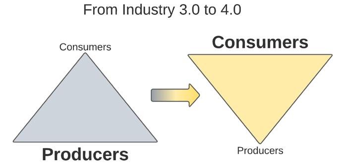
buildings should exist.
Enterprises adopting Industry 4.0 paradigms prioritize consumer applications during architectural development. Producer devices within the plant floor are largely static once commissioned. In brownfield deployments, device gateways can be deployed to bring legacy systems into compliance with the needs of the consumer application. As companies mature on their digital transformation journey, new information will appear, and applications will be deployed to consume it. The cost of integrating consumers into the enterprise must be minimized so small-value problems can be solved alongside large-value projects. An architecture that depends upon manual integrations for propagating information throughout the enterprise will limit the speed of innovation within the manufacturing and business processes. Architectures targeting technologies that enable easy integration of consumers will be prepared for the inevitable tsunami of applications looking to provide value for its business.
Standardizing Communication Infrastructure
Just as the TCP Model uses Ethernet switches to overcome the hurdle of connecting devices in different physical locations, a communications infrastructure implementing Data Brokers overcomes the burden of connecting consumers to data distributed across machines. Simple enterprise deployments can include a single, central Data Broker, whereas more complicated deployments can appear like network reference architecture diagrams detailing Core, Distribution, and Access switches.
As shown in the figure, "Point-toInfrastructure" architectures enable a consumer application to use a single Data Broker IP address rather than being required to know about the IP addresses of the individual
devices producing data. Additionally, the application only needs to implement a single communication protocol, dramatically reducing the burden of application development and commissioning efforts. The consumer application informs the Data Broker what data is of interest, and any data matching those criteria is immediately available. These benefits persist regardless of the number of producers placed on the network, which is why this architecture is scalable.
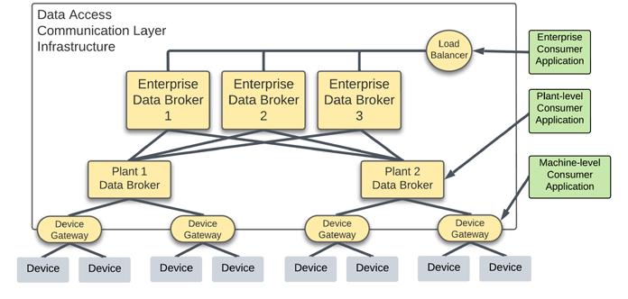
Once data is available at the enterprise level, applications can then begin consuming the data in any number of ways. For example, a business may be interested in the power levels across all equipment to evaluate the difference in energy consumption during an active shift compared to an idle shift.
The equipment generating this data resides on the plant floor, and the primary way to organize its information is by its location within a hierarchy of Plant / Area / Line / Cell. Most deployments will couple this location hierarchy to the data structure within a Data Broker. However, this data structure is a producer-centric approach that ignores consumers interested in specific data regardless of location. Any criteria driving a static data hierarchy within a Data Broker is not a consumer-centric approach as it does not facilitate requesting data irrespective of the attribute of interest.
Whereas a Data Broker decouples the connectivity of consumers from producers, the consumer remains strongly coupled to the number of producers. Data Brokers are just like Ethernet switches and do not define (1) how the data is encoded, (2) what datatypes are possible, and (3) what the data represents.
Each producer, therefore, may have its custom information definition, which will require an equal number of custom integrations within each consumer. Another
layer of standardization is necessary above the communication infrastructure to further simplify data access for the consumer.
Standardizing Information Infrastructure
Just as Device Gateways translate all the various industrial communications protocols, an Information Gateway commonizes all the different information encodings and structures. This central application enables information to be requested in meaningful ways, including dynamic filtering based on various attributes. No matter the number of information schemes or structures implemented by producers, consumer applications only need to be aware of a single information definition to receive that data through the Information Gateway.
Through a lightweight and standardized information interface, it enables both requestresponse patterns as well as subscription patterns. For example, an application can request a list of data to browse for what is available. This response includes data and descriptive metadata, which is static information tightly related to the underlying dynamic data. For example, metadata can include properties and attributes of data such as engineering units, calibration dates, location information, and many others. The metadata typically allows applications to filter for the data of interest when creating subscriptions. The gateway is consumercentric by providing data through a handful of encodings. The client can inform the gateway which one it prefers based on different use cases, such as JSON or binary formats.
In addition to translating the various ways of representing the data, the Information Gateway shields applications from needing to know the inner workings of the underlying Data Brokers, such as the topic hierarchy. For example, DNS helps web browsers from needing
the IP address of a webpage. Similarly, an Information Gateway translates an object name that is beneficial for humans into a cryptic topic name optimized for applications.
Within today's systems, integrating data producers requires knowing ahead of time what static publish path should be used for the data. Very often, this publish path is optimized for human readability rather than optimized for network bandwidth capabilities or data consumption patterns. The constraints of today's static topic names can be solved, however, with the Information Gateway behaving like a Dynamic Host Configuration Protocol (DHCP) server.
For example, when integrating a new data producer into the communication infrastructure, rather than using a static Data Broker IP address and static publish path, the producer may be configured with the address of the Information Gateway. The producer automatically connects to the Information Gateway, requests how its data should be published, receives a Data Broker address with a publish path, and then connects to the Data Broker to begin publishing the data. The broker and publish path provided by the Information Gateway can be based dynamically on any number of attributes as determined by enterprise architects, such as the device's physical location, type of device, or amount of data.
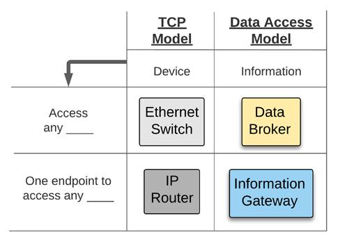
This dynamic request/response behavior for determining publish paths enables architects to centrally control how the data is published within the enterprise. It also enables network bandwidth optimization efforts not currently possible through statically defined publish paths. Deploying an automated information system may result in data traversing across many brokers as a swarm of unintelligible topic paths. However, fear not; this is already familiar territory for network architects capturing ordinary TCP/IP traffic from existing network switches.

After implementing a Data Broker and an Information Gateway, consumer applications become entirely decoupled from producers at the Transport and Communication Layers. This architecture allows consumers and producers to scale out significantly without much integration effort. The effort can be reduced further by deploying devices natively supporting the enterprise-wide Communication protocol and Information definitions. Once this is achieved, zeroeffort integrations are possible; consumers immediately receive information as soon as producers are connected to the Data Access infrastructure.
Wading through the Transition
Some within the industry suggest that data access architectures should first standardize on a communication method. Others recommend
that the focus should be on standardizing the information. Unfortunately, as has been discussed, the terms "MQTT" or "OPC UA" do not move manufacturers any closer to the goal of interoperability. Interoperability for Data Access goes beyond the particulars of the protocols at the Communication Layer
and data definitions at the Information Layer. When looking to achieve Data Access interoperability, the focus must start with the Information Gateway, the single interface for a consumer application.
While there are various technologies defined and multiple products on the market that can
11.2022 industrial ethernet book
serve information, the specific interface and function of the Information Gateway need to be standardized. The industrial market, therefore, is wide open for OEMs to develop products with custom interfaces and for end users to receive custom definitions of an Information Gateway and how it functions. Additionally, the lines between Information Gateway and Data Broker are beginning to overlap with newer products on the market. For example, Communication Layer software is starting to incorporate functions to allow some amount of Data Ops within their product. Additionally, Information Layer software primarily focused on Data Ops is beginning to include communication components such as MQTT Brokers.
As long as this critical definition remains undefined, data access interoperability will continue to be an elusive goal for the manufacturing industry. During this transitional period, end users and integrators must do their best with what is available. Since there is no standard defining the Information Gateway or the Data Broker, it is critical to begin with the consumer and then determine the interface for the producer. The Data Access Infrastructure must inherently eliminate the cost of integration when adding consumer or producer applications. Achieving a scalable architecture readies an organization to accommodate the multitude of use cases revealed as more data becomes available.
The first step in developing an architecture is to identify the primary consumer applications and define their requirements for information. Given that technology is only as good as the products that implement it, selecting an Information Gateway will inevitably include a make-versus-buy analysis, which determines if the solution will be a commercial-off-theshelf platform or a full-custom solution. To
assist the study, end users, integrators, and OEMs should consider using NASA's Technology Readiness Level (TRL) metric.
The TRL metric is scaled (1-9) to evaluate the maturity of a technology according to completed demonstrations. As the value of the metric increases, more of the system has been functionally demonstrated within environments of increasing fidelity: from artificial to relevant and then to operational. The figure on the bottom of page 51 adapts NASA's entrance criteria for manufacturers to guide discussions and evaluate risk among emerging data access technologies. It allows end-users, integrators, and OEMs to objectively decide what level of technical risk they can tolerate within their products and systems and communicate that to external parties.
When defining the scope of the Information Gateway, the interface and function must stay computationally lightweight, narrow in scope, and easy for consumers from multiple OEMs to implement. This interface will enable consumers to connect to a single endpoint to access information produced in any format within the enterprise. This standard interface, however, should be extensible to include other critical use cases such as events, historical access, and alarms.
Additionally, parts of the infrastructure must be identified to own the Data Ops process to transform various information definitions into the standard definition required by the Information Gateway. Smaller deployments may benefit from embedding the Data Ops function within the Information Gateway. Larger deployments, however, may distribute the Data Ops function across the enterprise and allow the infrastructure to scale as the number of producers and consumers increases.
After selecting an Information Gateway and establishing the Data Ops infrastructure,
communication protocols should be chosen to move data from the producers to the Information Gateway within the confines of the planned network infrastructure.
A deployed Information and Communications architecture will then levy interface requirements upon the producers, where conforming to these definitions enables integration at scale. However, where instantiating this interface definition within the device is impossible, account for efforts to manually integrate the custom information definitions through additional Data Ops or communication definitions through Device Gateways.
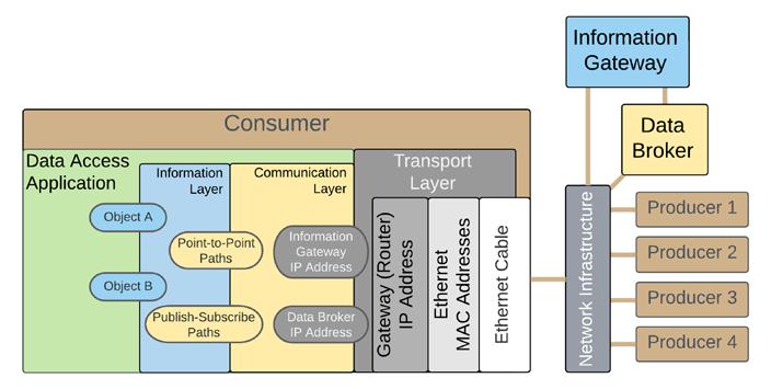
The industry desperately needs a standard definition of the interface and function of an Information Gateway and a Data Broker. Unfortunately, the current state of the market is reminiscent of the days of the protocol wars from forty years ago, before Ethernet switches and routers could be purchased from any number of vendors and form a functional infrastructure with minimal integration.
Until a simple stack is defined for the market to coalesce around, OEMs will continue to produce custom solutions, and end users will continue to expend their energy comparing the benefits of the technologies of each. Rather than settling for custom communication and information definitions or focusing on information models for specific industrial domains, let us focus on defining a standard Data Broker and Information Gateway that will transcend any single industrial environment. A transformed industry lies ahead, waiting only for a few decisive Data Access Architects to focus on making the integration of data consumer applications painless.
Protecting industrial networks: zero chance for hackers
The downtime of a production plant can be expensive. Companies therefore want to protect themselves against hacker attacks. Jürgen Greger, Industrial Communication Product Manager at LAPP, gives insights into the topic and reveals how to make life difficult for attackers.

IN 2021, HACKERS EXPERIENCED A BOOM. THEY have carried out some spectacular attacks, including critical infrastructures such as oil pipelines and waterworks. Industry is also subject to almost daily assaults. According to Prof. Axel Zimmermann from the Aalen University of Applied Sciences, incidents increase by more than 30 per cent annually. While malware, commonly known as viruses, was particularly popular with hackers, today it is phishing and, above all, ransomware. Here, the criminals encrypt all of their victims’ data and then extort ransom for decryption. It is likely to be successful, as few companies shout it from the rooftops when they are affected.
Companies can protect themselves using the defence-in-depth concept. An important aspect here are network components, which are secured ex-works in such a way that attackers cannot penetrate. Switches for industrial Ethernet and Profinet play the key role. LAPP has a wide portfolio of switches and routers that are assured to be state-of-the-art. Managed switches and NAT routers with a firewall are recommended in particular for maximum protection. They can be configured easily and are ready for use immediately.
Playing with fire
But technology alone is not the solution. Companies should have a holistic cyber security concept. Despite the dangers, only be 30 per cent of small and medium-sized companies have this, according to Axel Zimmermann. This is playing with fire. Companies are therefore in danger of losing intellectual property and business secrets, or having their production sabotaged. This can be expensive. A downtime in automotive production can cost millions of euros per day. It often also affects companies who are familiar with IT, such as Citrix. Here, hackers moving on the production network for five months undetected. Even FireEye, a security company for IT software, was hacked, looted and the security software stolen.
Some companies may ask themselves at this point: if IT companies cannot protect themselves, how are we going to succeed? Resignation is not an option, because you can protect yourself. Although it can never be done 100 per cent, the effort for the hackers should be as high as possible so that it doesn't pay off for the criminals. Support is provided
at the European level by ENISA, the European Agency for Cybersecurity, or in Germany by the German Federal Office for Security in Information Technology (BSI). Large companies maintain computer emergency response teams, or CERT for short. There are currently 48 CERTs in Germany, including the CERT Bundle from the BSI or VDE-CERT for the electrical engineering industry.
Availability is everything
Most industrial companies cannot afford this; they rely on external help. Their first point of contact is usually IT experts, whose main focus is on confidentiality. But this is not so important for companies. This is different if you ask experts from factory operation. With industrial security, also known as OT-Security, the focus is on availability. OT is about machinery and production facilities; as a 300 millisecond failure can be too much. Almost 100% availability 24/7 is everything here.
Many of these aspects are covered by a standard, IEC 62443. It is a comprehensive and internationally accepted standard for industrial security and describes the availability of systems in detail. Alongside a general section, it deals with processes, the system and individual components. The defence-in-depth concept is based on the standard. This is a multi-layered safety concept consisting of three parts: system security, network security and system integrity.
Defence-in-depth in focus
What exactly does the status quo concept entail? The three parts of the defence-indepth concept are broken down below and
11.2022 industrial ethernet book
SOURCE: ISTOCKsupplemented with information on this:
Plant safety: it is mainly about locking up systems, for example using special control cabinets. Not every person should have access to the network. This includes familiarising employees with work instructions and guidelines in appropriate training sessions.
Network security: One strategy is network segmentation, for example with NAT or VLAN. We recommend the use of IP and MAC filters, the deactivation of unused ports and the prevention of open ports being freely available in the network. It is also mandatory to use a firewall for secure communication with the outside world. There are smart solutions that separate individual machines or small production cells from the rest of the corporate network. Secure protocols should be used, for example when accessing a website.
System integrity: it mainly deals with system hardening. We are familiar with all default passwords such as 0000, which are stored by the device manufacturer in the delivered state. This should be replaced by a secure password immediately. This makes it as difficult as possible for hackers to attack a network. Other options include whitelisting and virus protection. Whitelisting, because companies know which components are allowed to communicate with one another, at least at the production level. By contrast, IT mainly relies on blacklisting because there is no way to know who wants to access your own website, which means that there are specifically prohibited areas. Authentication deals with user classification and password management (e.g. RADIUS or TACACS+).
If you take these recommendations into account, there is no way around managed devices in factory networking. LAPP has an extensive portfolio of switches for networking in factories that are equipped with the highest of security standards – making hacker attacks really difficult. LAPP is aware of the drastic effects of machine and factory downtimes. As a supplier of reliable connection solutions, the company sees it as its job to tackle the issue and protect its customers against downtime.
Jürgen Greger, Industrial Communication Product Manager, LAPP.How and why manufacturers develop into problem solvers
Advantage by means of service means producing innovative, high-quality or low-cost products is no longer enough. Companies need to think about how products solve problems, or function as a service.
SOURCE: LAPPCUSTOMERS
PURCHASE
SOLUTIONS, NOT products Companies therefore need to do more than just produce; they have to turn into holistic problem solvers. According to science, the way to doing this leads across five stages of evolution.
Many companies have long since left behind the first stage of being a dedicated manufacturer, but what do the other stages look like, and what is the best way to scale them? LAPP is also tackling this challenge: the company's portfolio already contains various services for its customers, including the new health check service for monitoring the data infrastructure in the Industry of Things area.
In 2017, Christoph Loos, CEO of Liechtenstein-based tool manufacturer Hilti said: “The customer wants to buy holes instead of hammer drills.” This statement, which has often been quoted in a sensible way since then, points out what manufacturers are feeling more and more strongly: technology alone does not offer customers any value, regardless of how sophisticated it is. They
have to benefit from it in some way, e.g. by solving a problem or improving a condition. And then there is also digitalisation, which allows customers to use machinery without buying it. X-as-a-service business models, be it X mobility, lighting or machining are becoming increasingly popular, and for a good reason: they have major advantages for customers and suppliers.
As a result, developing and producing innovative, high-quality or low-cost products is no longer enough. Companies need to think about how their products solve problems or fulfil a wish – or function as a service. The development from being a dedicated product manufacturer to a solution provider represents a spectrum when doing this.
From product provider to service provider
The FIR research institute at RWTH Aachen, which focuses on service and maintenance, describes the path from product provider to solution provider in five stages.

At the first stage, the company starts out as a dedicated product manufacturer. The product and its properties are clearly the main focus of the business model and the marketing. If the company already offers services at this stage, this takes place in an unsystematic way, and not as part of planned business revenue. At LAPP, this level is initially understood to be the production and sale of connecting components such as cables, plugs and switches. This is also where the entrepreneurial origin of the Stuttgart-based global market leader for integrated solutions in the cable and connecting technology area lies.
At the second stage, the company then also offers individual services which are sensible for the use of the product. One particular example from LAPP is the additional processing of logistics services and project management in project business.
The next stage involves services as a business model, which are an integral constituent of the offer together with the product, e.g. a
service with which the company offers madeto-measure solutions for its customers and the implementation thereof. LAPP can already be involved in the planning processes of machines, for example, whereupon individual adaptation and implementation of appropriate connecting components becomes possible.
Special cable configurators give the customer additional planning and ordering flexibility. In the ÖLFLEX® CONNECT system, the Stuttgart-based connecting specialist provides made-to-measure solutions from the design and drawing to the assembly and pre-installation of cable chains.


At stage four the company has arrived at an overall solution. The product is no longer the core constituent of the business model. It is now a case of comprehensive services for development, manufacture, operation and optimisation. For this purpose, LAPP now offers the Health Check Service for machine and plant areas. At level five and therefore at the peak is a company which provides a complete solution as a service in an operator model – the so-called "as-a-service" model.
Win-win for everyone involved
This transition across the 5 stages has many benefits for manufacturers and their customers. The acquisition of new machinery is usually a significant investment; which is sometimes difficult to bear, particularly in areas such as the woodworking and metalworking industries, which mainly consist of small and mediumsized companies in Germany. And once the machines have been purchased, there is the pressure of utilising them 24/7 in order to justify the costs – which is not always possible.
A metal processing company which no longer buys and operates its own machinery but buys in machining as a service can significantly reduce this economic pressure – usage-based billing removes the worry of
having order-related machine stop times, and can even make the production of small batches and single items economical. The suppliers of the overall solution in the operator model, i.e. machining in this case, now benefit from the fact that their machines are fully utilised, since many different customers can access them.
Health check service for network technology lays the foundations for transformation
For business models such as this to work, providers and customers must exchange large amounts of data – when the customer orders or pays for a service and when the provider follows up the usage, invoices, or monitors and optimises processes.
A high level of plant availability and networking of the machine with higher-level business processes and their production data are prerequisites for transformation in the sense of the Industrial Internet of Things (IIoT), which is where LAPP comes in with the
service model of the Health Check Service for network technology.
The background to this is that according to the Indusol Vortex Report, in 50 percent of all cases in 2021, machines failed due to connection problems at connectors, cables and switches, e.g. due to mechanical stress, ageing, substandard products, incorrect earthing and other factors. And if industrial machinery and their data connections fail, it quickly becomes expensive – and is extremely damaging for usage-based business models. LAPP wants to avoid this: the health check service analyses Ethernet and PROFINET systems, detects current and potential faults or weaknesses, and provides improvement suggestions.
In these cases, LAPP does not only support existing machinery, but can also be involved in machine planning and commissioning in order to identify probable interference and failure factors in advance. It therefore stands to reason for LAPP to provide this service, since the knowledge, the measuring instruments and the experience are available. Customers receive a reliable status analysis of their network technology, which increases machine availability and production efficiency; and LAPP ensures that the correct and reliable components are used – and recognizes the need for further development in its own product portfolio in the event of individual customer requirements.
LAPP has already successfully taken the fourth step on its way to becoming a service provider with services such as the health check service. LAPP has not yet reached the peak of the transformation. However, LAPP is aware that customers want to receive efficient production processes rather than purchasing individual components.
Timing challenges for multi-axis robotics and machine tool apps
In high performance, multiaxis, synchronized motion applications, control timing requirements are precise, deterministic, and time critical, with a requirement to minimize end-to-end latency, especially as control cycle times get shorter and control algorithm complexity increases.

INDUSTRIAL ROBOTICS AND MACHINE TOOL
applications involve the precise, coordinated movement of several axes in space in order to accomplish the job at hand. Robots typically have six axes that need to be controlled in a coordinated manner, and sometimes seven if the robot is moving along a rail.
In CNC machining, 5-axis coordination is common, although there are applications that utilize up to 12 axes in which tools and workpieces are both being moved with respect to each other in space. Each axis comprises a servo drive, a motor, and sometimes a gearbox between the motor and the axis joint, or end effector.
The system is then interconnected over an Industrial Ethernet network, usually in a line topology, as shown in Figure 1. A machine controller converts the required spatial trajectory to individual position references for each servo axis, and these are communicated over the network on a cyclic basis.
The control cycle
These applications run on a defined cycle time that is usually equal to, or a multiple of, the fundamental control/pulse-width modulation (PWM) switching cycle of the underlying servomotor drive. End-to-end network transmission latency is a key parameter in this context as illustrated in Figure 2.

Within each cycle period, the new position reference and other relevant information must be transmitted from the machine controller to each node of Figure 1. Then there needs to be sufficient time remaining within the PWM cycle for each node to update the servo control algorithm calculation using the new position reference, as well as any new sensor data.
Each node then applies the updated PWM vector in the servo drive at the same point in time via a distributed clock mechanism that is Industrial Ethernet protocol dependent. Depending on the control architecture, part of the control loop algorithm may be
implemented in the PLC, and it requires sufficient time to be available, having received any relevant sensor information update across the network.
Data transmission delays
Assuming that the only traffic on the network is the cyclic data flowing between the machine controller and the servo nodes, the network latency (TNW) is determined by the number of network hops to the furthest node, the network data rate, and the delays encountered in each node. In the context of robotics and machine tools, the propagation delay of the signal along the wire can be neglected, as the cable length is typically relatively short. The dominant delay is the bandwidth delay; that is, the time needed to get the data onto the wire.
For a minimum size Ethernet frame (typical for machine tools and robotics control), the bandwidth delay is illustrated in Figure 3 for both 100 Mbps and 1 Gbps bit rates. This is
simply the packet size divided by the data rate. A typical data payload for a multiaxis system from controller to servo would consist of a 4-byte speed/position reference update and a 1-byte control word update for each servo, which means a 30-byte payload for a 6-axis robot. Of course, some applications will carry more information in the update and/or will have more axes, in which case packets larger than the minimum size may be needed.
Apart from the bandwidth delay, the other delay elements occur as a result of the Ethernet frame passing through the PHYs and 2-port switch at each servo network interface. These delays are depicted in Figure 4 and Figure 5, where the movement of the frame is shown through the PHY into the MAC (1-2), through the destination address analysis where only the preamble and destination parts of the frame must be clocked through. Path 2-3a represents extraction of payload data for the current node, whereas path 2-3b represents the onward journey of the frame to the destination node(s). Figure 4a shows only the payload being passed to the application in 2-3a, whereas Figure 4b shows the bulk of the frame being passed; this is indicative
of small differences that can occur between Ethernet protocols. Path 3b-4 represents the outbound transmission of the frame through the transmit queue, through the PHY and back out onto the wire. This path does not exist on a line end node as shown. Cut-through packet switching is assumed here, rather than storeand-forward, which has much higher latency as the entire frame is clocked into the switch before it is forwarded on.
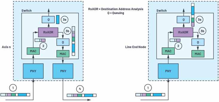
The delay elements of the frame are also shown in Figure 5 along a timeline, where the total frame transmission time through one axis node is illustrated. TBW represents the bandwidth delay, while TL_1node represents the latency of the frame through a single node.
Apart from delays related to the physical transmission of the bits over the wire and the clocking in of address bits for destination address analysis, PHY and switch component latencies are the other elements that impact the transmission delays within the system. As the bit rates on the wire increase and the node count expands, these latencies become even more important in the overall end-to-end frame transmission delays.
Low latency solutions
Analog Devices has recently released two new Industrial Ethernet PHYs designed to operate reliably in harsh industrial conditions over extended ambient temperature ranges up to 105°C and with industry-leading power and latency specifications. The ADIN1300 and ADIN1200 were developed specifically to address the challenges outlined in this article and make ideal choices for industrial applications. With the fido5000 real-time Ethernet, multiprotocol, embedded 2-port switch, Analog Devices enables solutions for deterministic time-sensitive applications.
The latencies introduced by the PHY and switch are listed in Table 1, assuming that the receive buffer analysis is destination address based and assuming a 100 Mbps network.
As an example, aggregating these delays up to a 7-axis line network, and including the clocking of the full payload into the final node, the total transmission delay becomes where the 58 × 80 ns represents the remaining 58-byte payload after the preamble and destination address bytes have been read. This calculation assumes that there is no other traffic on the network or that the network is

managed to enable priority access for time sensitive traffic. It is also somewhat protocol dependent, with slight variations in the calculation being introduced depending on the exact Industrial Ethernet protocol used. Referring back to Figure 2, in a machine system with cycle times down to 50 µs to 100 µs, the frame transmission to the furthest node can take up to almost 50% of the cycle, reducing the time available to update the motor control and motion control algorithm calculations for the next cycle.
Minimizing this transmission time is important for performance optimization, as it allows longer and more complex control calculations. Given that delays associated with data on the wire are fixed and related to the bit rate, utilizing low latency components, such as the ADIN1200 PHY and the fido5000 embedded switch, is key to performance optimization, especially as node count increases (for example, 12-axis CNC machine) and cycle times reduce.
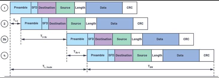
Moving to gigabit Ethernet dramatically reduces the impact of bandwidth delay, but increases the proportion of overall latency introduced by the switch and PHY components. For example, a 12-axis CNC machine on a gigabit network will have a network transmission delay of approximately 7.5 µs. The bandwidth element of this is negligible, and it makes little difference whether minimum or maximum Ethernet frame sizes are used.
The network delay is split approximately equally between the PHYs and the switches, underlining the value in minimizing the latency in these elements as industrial systems move toward gigabit speeds, control cycle times reduce (EtherCAT® has demonstrated 12.5 µs cycle times), and node count expands with the addition of Ethernet connected sensors in the control network and the flattening of network topologies.
Conclusion
In high performance, multiaxis, synchronized motion applications, control timing requirements are precise, deterministic, and time critical, with a requirement to minimize end-to-end latency, especially as control cycle times get shorter and control algorithm complexity increases.

Low latency PHYs and embedded cut-through switches are important elements in optimizing these systems. To address the challenges outlined in this article, Analog Devices has recently released two new robust Industrial Ethernet PHYs, the ADIN1300 (10 Mb/100 Mb/1 Gb) and ADIN1200 (10 Mb/100 Mb).

Transport changeover time plunges from 1 hour to 1 minute
An XTS-based assembly line uses an advanced automation control system to minimize the machine footprint for automotive industry customers. After a second modernization project, two different types of pumps can be produced on a highly condensed assembly line with the same small footprint.
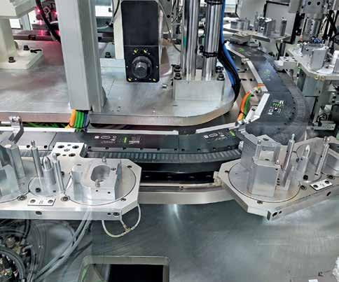
HOW DO YOU DESIGN A NEW ASSEMBLY LINE and go on to reduce the footprint of the concept by another quarter? And how can you later increase the productivity of this highly consolidated line even further? Canadian automation expert Eclipse found the answer in the linear XTS transport system from Beckhoff. After the second modernization, the assembly line can produce two different types of pumps on the same small footprint.
Eclipse Automation in Cambridge, Ontario, was founded in 2001 to serve the custom automation market and has grown exponentially. “We serve many different market segments in addition to automotive and transportation, such as life sciences, consumer products and even nuclear energy,” said Jeff Werner, General Manager for Eclipse. The company constantly researches leadingedge solutions to help customers not just succeed in but truly disrupt their industries. “We test all kinds of new technologies, including artificial intelligence, remote training, virtual reality for maintenance systems and any components that add precision and flexibility,” Werner said. “One technology that has proven particularly important to us is linear transport systems.”
Recently, Eclipse updated a successful system for a customer that uses the eXtended Transport System (XTS) to assemble automotive transmission pumps. This customer had requested the first system to replace several legacy machines.
At that time, the machines could not achieve the throughput and quality standards necessary for this high-volume product, according to Matthew Kelly, Software Design Supervisor at Eclipse: “The previous machines used rotary dial tables and similar components. Each station only did one process, and if any station went down, it impacted the entire line.”
While increasing functional capabilities, the custom solution from Eclipse needed to minimize footprint. “Floor space is always at a premium, but this customer’s assembly and process equipment is extremely consolidated. When we proposed the system, they said, ‘We like the concept, but make it 25% smaller.’ We didn't know if that was possible,” Werner said. To solve these challenges, Eclipse worked closely with the local Beckhoff Canada team,
With the highly flexible XTS for material handling, Eclipse was able to produce a very highly condensed assembly system for its automotive-industry customer. Picture: © Eclipse Automation
completed pump in front of two GigE cameras for a final vision inspection, then places it on a conveyor for outfeed.
Initial machine design proven in the field
The XTS-based assembly line features four separate cells with more than 50 stations for pressing, soldering, screwdriving, flatness checks with LVDTs, dispensing, plasma treatment, leak testing, inspection, etc. Many stations require precise synchronization to robotics.
In the first three machine cells, operators place the pumps on pallets attached to XTS movers. The XTS systems are 12 m long with 18 movers in the first cell, 6 m with 12 movers in the second and 10 m with 18 movers in the third. The carefully calculated pitch of the pallets enables micron-level positioning. When all assembly processes are complete, the operator moves the pump to the next cell. At the third cell, a small conveyor moves the pump to the fourth cell where a robot lifts the
11.2022 industrial ethernet book
“XTS transitions products from station to station very quickly and accurately, and if there's an issue with a part at any point in the process, we can bypass other stations and simply remove it,” Kelly explained. “We grouped multiple processes into a single station, which helped us further decrease footprint. With all the processes and tooling, it was the most condensed automation system I’ve ever seen.”
New requirement for higher productivity
The first Eclipse assembly machine exceeded expectations and is still in use today. In December 2019, however, the automotive supplier requested a second machine with a new challenge: It would need to make a second pump on the same system. The pumps are different sizes and for different
vehicle makes. This posed a challenge for the previously designed pallets, not to mention that some assembly steps happen in different orders for the two pumps. To maintain high throughput, the system couldn’t afford the downtime to purge all of one pump type and then perform a lengthy changeover.
Working with the local Beckhoff team, Eclipse created a new concept relying on the fast cycle times of EtherCAT and the flexibility of XTS. “The system allows operators to quickly release and replace the pallet with a second type. This new pallet indexes forward and its specific position is measured to determine an offset. We apply those offsets to each individual pallet and make sure that components and parts line up exactly for the processes. So, the operator can easily load part type A, wait one cycle, and then load part type B with negligible downtime,” Werner said.
Also, because each mover appears as an individual motion axis, they are not linked as in traditional designs. Instead, they can freely move workpieces around the track to specific process steps as needed, even if the order is different between the two pumps.

Complete automation solution
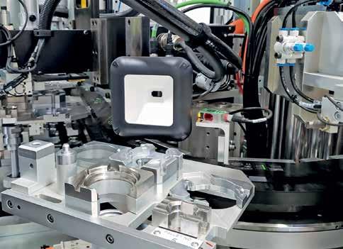
In addition to the three XTS systems, the assembly line relies on other EtherCAT and PC-based automation technologies from Beckhoff. Each of the first three cells features a C6930 control cabinet Industrial PC (IPC) to control the cell’s XTS track and peripheral devices.
TwinSAFE is implemented for functional safety across the entire line, and the IPCs communicate via EtherNet/IP to a secondary machine controller that controls other portions of the line. However, EtherCAT provided the system’s main communication and I/O. “Real-time EtherCAT synchronization with robotics and servo components allowed the engineers to perform interpolated motion for different dispense processes – in particular, applying adhesive in intricate patterns,” explained Herron.
To make this advanced functionality possible, TwinCAT 3 automation software was critical. The universal engineering and runtime platform from Beckhoff allowed Eclipse engineers to program G code that enables the XTS and Beckhoff AM8000 servomotors to perform coordinated motion for high precision dispensing. In addition, Eclipse took advantage of the capability to program with the object-oriented extensions of IEC 61131-3, predefined and custom function blocks, and computer science standards found in Microsoft Visual Studio®. “For programming pallet control, pallet offset tables and similar requirements, Beckhoff offers many advantages compared to other options, and we save a significant amount of engineering time,” Kelly pointed out.
Fast product changeovers deliver instant results
With the innovative design by Eclipse, the updated transmission pump assembly system met the specified cycle time of 20.2 s per part with the micron-level accuracy required. Since commissioning finished in early 2021,
the system has produced roughly 1,000 parts per shift, running part A and part B in separate batches.
The easy release and attachment of pallets, along with the instant automatic indexing of XTS, almost eliminated changeover times, pushing them down from more than an hour to just one minute. “The customer was absolutely overwhelmed by the ability to perform that changeover considering the system’s extreme compactness and complexity of process,” Werner said. Both controls and mechanical engineering ensure easy release of these pallets without removing a single bolt. Pallets simply move to a storage buffer, and if one is damaged, the operator can easily replace it.
According to the company’s experts, Eclipse has kept innovation in its DNA. The company has tackled many other unprecedented high-speed and micro-assembly applications, including several Covid-19 test kit applications that also use XTS and PC-based control. Werner sees this as important for providing highly efficient, cost-saving solutions to customers as well as attracting new engineering talent to work at Eclipse.
“Most students are not learning traditional PLC programming. Instead, they leave university with a far better understanding of PC-based control systems than ever before, and that grows every year,” he said. “Beckhoff has proven to be a reliable partner for this as well as all areas of automation technology.”
Ethernet-APL for end users and device manufacturers
Ethernet-APL (Advanced Physical Layer) offers considerable benefits for end users in the process industry by facilitating seamless connectivity between field devices using the Ethernet protocol and greatly simplifying the creation of high-performance automation networks.

FROM SIMPLE SENSORS TO COMPLEX, ANALYTICAL instruments, we find millions of installed devices in process manufacturing – with millions more being added every year. Even today, most devices still use 4–20 mA technology, maybe supplemented by digital point-to-point communication over the HART protocol.
This is true even though, roughly three decades ago, digital field buses like PROFIBUS PA and FOUNDATION Fieldbus H1 were introduced, which use a centralized communications network to supply control systems with other measurement data in addition to simple process values, plus many parameters and field device states. Apparently, the deployment of these field buses is restricted to comparatively few –often highly specialized – applications, due to their complexity and performance data.
Considerable expertise is required, and specialized gateway components are also needed to integrate them into upstream
Internet infrastructure. Alongside triggering additional hardware costs, configuring these network gateways also requires quite a bit of configuration effort.
Last year, with the aim of removing these obstacles, a new standard, Ethernet-APL, was adopted for continuous Ethernet communication down to field devices. The standard accounts for the specific requirements of the process industry, like the bridging of large distances with a simple, two-wire conductor that not only handles data communications but also supplies power to the connected field device. At 10 Mbps, transmission rates are far higher than with HART and field buses. Corresponding performance definitions also allow the implementation of intrinsically safe devices. Since Ethernet-APL limits itself to defining a new data exchange standard for Ethernet at the lowest layer, it retains compatibility with arbitrary Ethernet-based protocols at higher layers. For the first time, this enables
11.2022 industrial ethernet book
transparent communications between production and even corporate networks right down to the field device, without the need for gateways. It also allows a free choice of automation protocol and other conveniences like web servers, OPC UA, and cloud/edge connectivity.
Ethernet-APL is easily mature enough to permit the deployment of corresponding devices in production environments. Both end users and device manufacturers face challenges when getting started with this technology, however: the ideal scenario is for the pool of deployed components to be as broad-based as possible. With suitable infrastructure components and communications modules for field devices, this “waiting game” can be minimized – as is explained in the following.
The different network topologies for Ethernet-APL
The Ethernet-APL Engineering Guideline describes three separate network topologies
for Ethernet-APL networks.
The situation for the Ethernet-APL spurs is the same for all three topologies. Ethernet-APL devices can be connected to a switch by a Category IV cable no more than 200 m in length and can communicate at a transmission rate of 10 Mbps.
In the first topology scenario discussed, an APL field switch is connected directly to a standard Industrial Ethernet network.
Whether the field switch is installed in an electrical enclosure or in the field will depend on the circumstances on-site.
The control network in this scenario can be implemented using normal Ethernet copper cables or optical fiber. The typical transmission rate in this section of the network will be 100 Mbps.
The other two topology scenarios utilize an “APL trunk”. This involves using an Ethernet-APL trunk to connect the APL field switch to the control network. The two alternatives differ in terms of the power supply via the APL trunk.
Softing assumes that many installations will pick the first topology scenario, with direct integration of the APL field switch into the control network. For this purpose, the new aplSwitch product line from Softing provides a field switch, which can be connected to the control network either with copper or optical fiber.
Optimized variants will be provided for installation directly in the field and the control cabinet. The first Ethernet-APL field switch, available as a prototype, is a variant
Standard Ethernet topology.
for direct installation in the field and allows the connection of Ethernet-APL field devices in Ex Zone 1 and 0.
Network stability
Monitoring the load that Ethernet-APL devices are exposed to is essential to ensure the stable operation of PROFINET networks. Otherwise, there is the risk of load peaks causing the sporadic failure of individual devices. Where networks transition from 100 Mbps

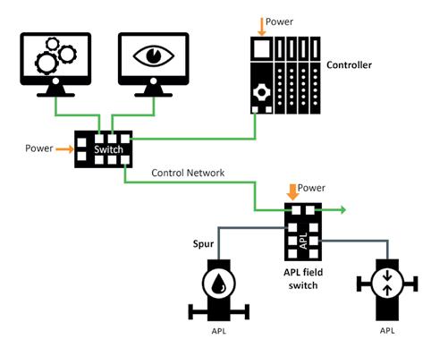
to 10 Mbps, a higher network load in the 100 Mbps control network is especially critical for the Ethernet-APL devices on the 10 Mbps spurs, as their data throughput is just 10% of the control network.
In this case, the IEEE (Institute of Electrical and Electronics Engineers) envisages limiting ingress and egress data traffic at switch ports. Softing’s Ethernet-APL switches support these net-load rate limits, therefore making a key contribution to keeping networks stable.
Trunk-and-spur topology.
PROFIBUS PA devices
As organizations start rolling out Ethernet-APL, they will encounter the problem of not having enough of the devices in their plant available as Ethernet-APL models. In the specific case of PROFINET Ethernet-APL networks, this problem can be mitigated by substituting existing PROFIBUS PA devices for these non-existent PROFINET Ethernet-APL devices.

To date, integrating PROFIBUS PA devices into a PROFINET network has meant using PROFINET-PROFIBUS PA proxy gateways like Softing’s pnGate PA. But to avoid users having to install additional gateways during the transition period, it makes sense to integrate the PROFINET-PROFIBUS PA proxy into the Ethernet-APL field switch. This allows PROFIBUS PA devices to be connected directly to the switch.
Models with an integrated PROFINETPROFIBUS PA proxy are available for all Softing Ethernet-APL field switches. In technical terms, the switch creates an extra PROFIBUS PA network segment, to which the PROFIBUS PA devices then connect. Modules that are shown in the switch’s PROFINET device can then be used in the PROFINET controller to access the data from the PROFIBUS PA devices.
Ethernet-APL PROFINET devices and PROFIBUS PA devices both implement the PNO PA profile, so the data that is provided is similar in each case and can be converted easily when switching from PROFIBUS PA to PROFINET.
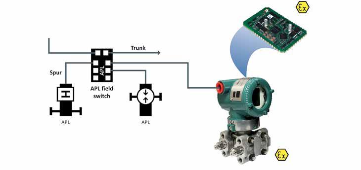
Field devices
To make process equipment that was previously operated using HART available for Ethernet-APL as quickly as possible, device manufacturers can avoid having to start development from scratch by opting for a redesign that utilizes an electronics module providing all of the
hardware and software components needed for communications.
A conventional hardware development project would require companies to implement and validate all of the Ethernet-APL interface aspects (physical connection, power supply and monitoring,…) themselves. Effort would also be needed to port a protocol stack, and implement device properties (profile) as well as the actual device application with its dynamic behavior.
Once complete, this device would then need to pass various kinds of conformity tests and certifications. Alongside EMC and environmental testing, this would also include APL Physical Layer Conformity, plus Ex certifications and conformity testing from the various Fieldbus organizations, as required. Past experience shows that this involves major effort and development times lasting up to several years. But by using a compact, pre-certified, and configurable electronics module like Softing’s commModule APL, however, many of the tasks mentioned above can be skipped or considerably shortened.
As a low-cost SMD hardware module, commModule APL not only handles the
required Ethernet-APL connectivity but also offers application software that can be easily configured to implement the required behavior from the respective field device. Existing HART and Modbus devices can be migrated to Ethernet-APL without a single line of code having to be written. To achieve this, their previous hardware communications port is now provided fully digitally by the module’s UART pins.
A configuration tool is then used to define all of the necessary assignments to the device application’s existing HART or Modbus commands and load these permanently onto the module. The module software handles the mapping to the automation protocol autonomously on the basis of this configuration. The module also supplies power to the application electronics, sourcing both this energy and the power it needs itself directly from the Ethernet-APL connection.
This considerably simplifies a hardware redesign for a field device. Perhaps the biggest benefit to device manufacturers is that the module has already passed a wide range of reference certification and conformity testing. This reduces development risk while providing reference data for the relevant certification needed by the overall field device.
Another key advantage offered by a module solution is that it is a standard product in the portfolio of its manufacturer, who in maintaining this product can independently accommodate further developments in the relevant protocol profile specifications, as well as supply chain issues, and so relieve the field device manufacturer of these burdens.
New Industrial Ethernet switch portfolio
Next-generation Ethernet switch portfolio optimizes potential of industrial networks.
Moxa announced a next-generation Ethernet managed switch portfolio designed to futureproof networks and accelerate digital transformation in the IIoT era.
An expanded portfolio consists of EDS-4000/ G4000 Series DIN-rail switches, MDS-G40004XGS Series modular DIN-rail switches, and RKS-G4028 Series rackmount switches, all optimized to build robust, secure, and easily scalable networks from edge to core.
Moxa’s newest switches ensure continuous, reliable transmission of real-time surveillance feeds and other high-volume data by supporting Turbo Ring and Turbo Chain (recovery < 20ms), dual isolated redundant power supplies, along with STP/RSTP/MSTP for network redundancy. Moxa MXstudio software is supported by all models to achieve easier, fully visualized network management.
The EDS-4000/G4000 Series of DIN-rail Ethernet managed switches offer a comprehensive selection of 68 models ranging from 8 to 14 ports with features such as 90-watt 802.3bt PoE and 2.5 GbE Connectivity. Compliant with the IEC 62443-4-2 security standard, these hardened switches carry multiple industrial certifications for railway,
New switches ensure continuous, reliable transmission of real-time surveillance feeds and other high-volume data.
marine, power, ITS, and other demanding applications.
The RKS-G4028 Series of rackmount full Gigabit Ethernet managed switches are available in 22 models with up to 28 full Gigabit ports and 802.3bt PoE++ support. The switches are compliant with the IEC 62443-4-2 security standard and IEC 61850-3/IEEE 1613,
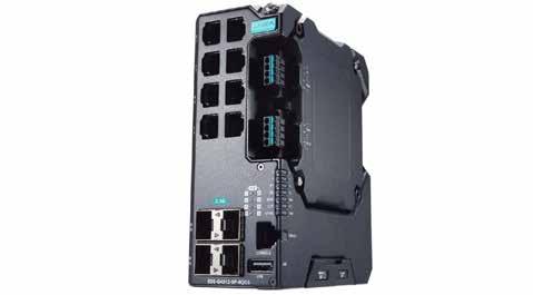
New edgePlug FANUC CNC
Softing expands its edgePlug family with edgePlug FANUC CNC. The Linux-based Docker container provides control data for use in Siemens Industrial Edge applications.
The Docker-based software products of Softing's edgePlug family connect controllers to applications in the Siemens Industrial Edge, an open, directly deployable edge computing platform. The new edgePlug FANUC CNC can be used to read machine and manufacturing data from FANUC CNC product series. Since May 2022 edgePlug SINUMERIK CNC is already available for accessing data from Siemens 840D CNC controllers. In a later step, access to SIMATIC S7 data will also be possible.
The edgePlugs are available in the Siemens Industrial Edge Marketplace and can be configured via the integrated Siemens Industrial Information Hub (IIH) tool. The purchase and licensing of the edgePlugs are fully integrated into the Siemens Industrial Edge Market Place. The licensing model is scalable and based on the number of control connections required.
The edgePlugs can be used for all edge, cloud, and on-premise applications that
require access to control or machine data. The applications use the OPC UA servers or MQTT brokers available in the Siemens Industrial Edge to access the data provided. The edgePlugs in turn use Ethernet to connect
plus IEEE 1588 PTP for high-precision time synchronization. The MDS-G4000-4XGS Series provide a choice of up to 24 Gigabit and 4 10GbE Ethernet ports.
to the controllers.
Softing Visit Website
Gigabit Ethernet transceivers
Microchip’s LAN8840/41 are single-port Gigabit Ethernet transceivers delivering PTP-v2 (IEEE 1588-2008) time stamping for highly coordinated factory and process automation Developers of industrial automation systems are looking to shift away from the reliance on proprietary solutions for process synchronization to standard-based solutions that offer broader compatibility and reduce design costs. To deliver critical process synchronization, Microchip Technology Inc. (Nasdaq: MCHP) announces the LAN8840 and LAN8841 Gigabit Ethernet transceiver devices that meet IEEE® 1588v2 standards for Precision Timing Protocol. The LAN8840/41 Ethernet devices are enabled with Linux® drivers and deliver flexible Ethernet speed options including 10BASE-T, 10BASE-Te, 100BASE-TX and 1000BASE-T.
The LAN8840/41 devices can facilitate critical packet prioritization by providing high-speed time stamping that is then relayed between the various components to determine network latencies, accommodate for those latencies, and synchronize time amongst all connected devices. This functionality is key for process automation applications that require precise
control production systems such as robotics, distributed sensors and cooling and mixing systems. Designed with robust applications in mind, the LAN8840/41 devices can withstand extended industrial temperatures ranging from -40°C to +105°C.
To help companies achieve sustainability goals by reducing a network’s power consumption, the LAN8840/41 offers features
like Wake-on-LAN (WoL) and energy-detect power-down mode.
Additionally, Energy-Efficient Ethernet (EEE) delivers low-power idle and clock stoppage modes for optimal power performance.
Microchip
Low-profile touchless switches
LED illumination and indoor/outdoor durability low-profile touchless switches for industrial applications.

A new line of CW low-profile touchless switches suitable for many hygienic industrial and public automation applications, addressing cleanliness concerns for protecting against COVID-19 and other contamination. Touchless switches are durable and reduce total cost of equipment operation.
The CW touchless switches are designed with a sleek and nearly flush (just 2mm rise) low-profile surface silhouette. They are built for an industry standard 22mm mounting hole and require only a shallow 35mm space behind the panel face, plus room for the wiring connector. The typical installation pitch is 30mm width and 50mm height. Operating temperatures range from -25 to +55DegC.
A rubber washer and locking ring ensure IP65/67 and NEMA Type 4X ratings are maintained. The CW1H housing and bezel is black plastic resin, and the CW4H is silver aluminum alloy metal. Although the switches are rated for outdoor use, are made from weather resistant materials, and are highly resistant to visible light, excessive exposure to ultraviolet rays from direct sunlight can cause material degradation and color fading,
and even false signals.
Additionally, as with almost any signaling device, dirt and water droplets can impact operation. Therefore, designers should check product performance before use, and consider
degrees of physical protection.
IDEC Corporation
Visit Website
IO-Link Sensor for industrial applications
One sensor with IO-Link provides a solution for multi-position measuring up to eight positions.
Temposonics has announced the expansion of its E-Series IO-Link for industrial applications. These linear position sensors with IO-Link are now available with multi-position measurement, enabling the detection and output of up to eight positions simultaneously.
The E series is suitable for the requirements of various industrial applications. Especially their compact design enables the use of magnetostrictive sensor technology in limited space. In 2016, Temposonics was the first company to offer a complete range of magnetostrictive position sensors with IO-Link.
The upcoming upgrade will continue this trend: the multi-position measurement with up to eight positions for a linear position sensor is presently only offered by the E-Series IO-Link from Temposonics. With up to four positions, the velocity value can be measured in addition to the position value.
By determining several positions on only one sensor, the need for additional sensors is eliminated resulting in streamlined measurement. It means that while maintaining precision, costs are reduced and processes are simplified. For example, in the cutting and
By determining several positions on only one sensor, the need for additional sensors is eliminated.
winding of materials such as paper and film. In such systems, several knives and trim tapes usually move on one rail. Until now, a sensor was used for each knife. Due to multi-position measurement, the positions of up to eight knives or trim tapes can now be monitored with just one sensor.
The well-known advantages of IO-Link
technology, such as fast initial commissioning and condition monitoring at every level of the machine through diagnostics down to sensor level, are still available.
Managed Industrial Ethernet switches
Certified rackmount switches
strengthen network security using Moxa's IEC 62442-4-2 cybersecurity.
Substation automation systems will benefit from RKS-G4028 series Gigabit Ethernet managed switches that serve as foundational building blocks in power substations with up to 28 Gigabit ports to fulfill future scalability requirements, modular interfaces for flexible connector combinations, certified IEC 62443-4-2 enterprise-grade cybersecurity, and compliance with IEC 61850-3 high EMC immunity requirements. Available in 22 designs, RKS-G4028 Series switches deliver maximum versatility with options that include: Layer 3 switching functionality, 24 VDC, 48 VDC, or 110/220 VDC/VAC dual isolated redundant power supplies, and PoE++ support for powering 90W field devices.
In addition to utilities, RKS-G4028 switches extend themselves to railway workloads due to their compliance with EN 50121-4 performance criteria for signaling and telecommunications equipment. Plus, by supporting Turbo Ring and Turbo Chain (recovery time < 20 ms @ 250 switches), and STP/RSTP/MSTP for network redundancy, combined with an operating temperature range of -40 to +75° C, RKS-G4028 switches are well-suited for the
most demanding factory automation use cases. Hardware-based IEEE 1588 PTP (Precision Time Protocol) achieves clock accuracy in the sub-microsecond range, helping IT professionals unleash new possibilities in industrial measurement and SCADA control.
Moxa developed RKS-G4028 switches according to IEC 62443-4-1 lifecycle guidelines to ensure compliance to the IEC 62443-4-2 cybersecurity international standard. IEC 62443-4-2 describes the capabilities that industrial control system components must feature including account, identifier and
authenticator management; password-based authentication; public key authentication; use control; data integrity and confidentiality; as well as backup for resource availability.
As a result of this certification, RKS-G4028 switches improve the security posture of industrial networks and provide deep visibility into high-risk environments where critical services are delivered.
Intelligent motion controllers
New motion controller series is powerful, modular and designed for the global industrial market.
Intelligent, multi-axis Parker Motion Controllers combine machine logic, real-time motion control, advanced safety features and visualisation in a completely scalable solution.
The electro-mechanical Parker Motion Controller series is ideal for OEMs building packaging, material forming, printing or handling machines, as well as system integrators providing factory automation solutions for the automotive, textile, papermaking and food and beverage industries. Based on robust, fan-less ARM CPU architecture, the series consists of the PAC120 and PAC340. These compact industrial programmable controllers form part of a system of I/O modules for linking process signals within an EtherCAT network.
Using the leading vendor-independent CODESYS SoftMotion platform for quick and easy programming, Parker Motion Controllers offer dedicated functionalities to allow the optimal development of motion control applications. Everything is integral within a single user interface so that engineers can work smarter, more efficiently and more effectively based on the IEC 61131-3 and PLCopen Motion standards.
Notably, the modular PAC architecture is expandable with a safety controller and safety
I/O modules to meet the requirements of the Machinery Directive 2006/42/EC. Engineered for easy configuration into existing plant networks, the Parker Motion Controller series comes as standard with a variety of on-board communication protocols, including an OPC UA server, Modbus TCP, EtherCAT and dual LAN networks, along with additional options for Ethernet/IP, PROFINET
and PROFIBUS. The OPC UA server facilitates integrated Industry 4.0 connectivity. USB ports and a built-in SD card slot enable local storage of process data and exchange of control programs.

Fiber optic transceiver products
New line offers more wavelengths, longer distances, and faster data rates.
The more than 300 new coarse wavelength division multiplexing (CWDM) and dense wavelength division multiplexing (DWDM) products represent additional wavelengths, distances and data rates supported, compared to L-com’s previous transceiver offerings.
Fiber optic transceivers convert a switch’s or router’s electrical signal to an optical signal, then change it back to an electrical signal at the receiving device. L-com’s new additions are expected to be particularly useful for telecommunications service providers, cable TV multiple system operators (MSOs), data communications companies and enterprise networks, and in government network applications.
The new fiber optic transceivers add to the existing portfolio of “grey” wavelength transceivers (850 nm, 1310 nm and 1550 nm) with both CWDM and DWDM wavelength options. The CWDM transceivers are offered in eight different wavelengths (1470 nm through 1610 nm, in 20 nm increments). The DWDM transceivers are offered in 40 different channels, from channels 20 through 59 (1530.33 nm through 1561.41 nm
wavelengths, in 0.8 nm increments).
More than 30 of the new models support fiber optic lines of up to 120 kilometers at both Gigabit Ethernet and SONET OC-48 data rates. Additionally, the product line now features grey 1G and 10G optics for multimode and single-mode fiber deployments.
This expansion of L-com’s line includes
11.2022 industrial ethernet book
more than 100 new offerings in the SFP, SFP+ and XFP form factors. In addition, the new models broaden 29 of the 38 OEM platforms with which L-com’s line is compatible.
L-Com Visit Website
Industrial PoE switch
New switch supports networking for devices, security cameras, wireless access points and monitors.
A new compact industrial Power over Ethernet (PoE) switch is designed to support the ever-growing networking requirements for devices, such as security cameras, wireless access points and monitors. The Lynx 3510 PoE series is capable of supporting networks with greater power demands and is ideal for handling big data, high bandwidth, missioncritical applications typically found within transportation, manufacturing, energy and smart cities.
With power and data provided over the same cable, PoE helps to reduce network complexity and offers greater installation flexibility, reliability, and time and cost savings. The Lynx 3510 PoE enhances network capability by supporting the needs of more powered devices, with eight copper ports each providing gigabit speeds and up to 30W output. This is ideal for connecting HD IP CCTV cameras in industrial settings and other power-hungry applications. The Lynx 3510 PoE also offers redundant and fast failover connectivity, with Westermo’s FRNT ring protocol ensuring rapid network recovery should a node or connection be lost.
Ensuring the security of industrial data communication networks is of paramount
importance, especially with cyberattacks becoming increasingly sophisticated. To reduce risk and increase cyber resilience, the Lynx 3510 PoE has an extensive suite of advanced cybersecurity features. These can be used to build networks in compliance with the IEC 62443 standard, which defines technical security requirements for data communication network components.
The DIN rail-mountable Lynx 3510 PoE has been extensively tested to meet a broad range of industry standards relating to electromagnetic compatibility, isolation, vibration and shock.
Westermo Learn More
Multiprotocol Industrial Ethernet switches
New platform offers pre-certified protocol solution that reduces development time.
A new multiprotocol Industrial Ethernet switch platform addresses the connectivity needs of industrial and process automation, motion control, transportation, and energy automation. The Industrial Ethernet switch platform is designed to operate in a star, line, or ring topology.
The ADIN2299 offers a highly integrated and tested solution that contains a communications controller, a two port 10/100Mbps ethernet switch, memory, physical layer (PHY), and protocol stacks.
The ADIN2299 hardware, coupled with its software and pre-certified industrial protocols, reduces system integration time while providing fast time to market. It reduces design and debug time by not only providing the protocol stack but also the RTOS, file system, drivers, and TCP/IP. An application processor can connect to the switch platform via a UART, SPI or Ethernet interface. The ADIN2299 software enables the application processor to connect to a unified interface so that various industrial protocols can be utilized without requiring any changes to the application processor software. This
eliminates the learning curve associated with incorporating additional protocols.
Customers can leverage a single field device hardware design to support multiple industrial protocols. Another element of the ADIN2299 is cybersecurity. It has a secure boot and secure update feature which ensures that only verified code is executed, reducing possible disruptions in the field caused by cyberattacks.
An ADIN2299 evaluation kit is available for platform assessment and system development.
An example is provided to demonstrate end-to-end, host-to-network and interface-to controller communication. Once a development board is connected via UART, SPI, or Ethernet interface with the ADIN2299 evaluation board, protocol communication can be evaluated using a PLC or controller simulator.
Analog Devices
Learn More
Motor control MPU & Ethernet
Combines high performance motor control and TSN-Compliant Industrial Ethernet network on a single-chip.
The RZ/T2M combines fast and highly precise real-time motor control capabilities and the latest industrial Ethernet on a single chip, while also supporting functional safety operation. By providing all essential peripheral functions for motor control, the RZ/ T2M enables customers to reduce the number of external components.
The RZ/T2M is built around two Arm Cortex®-R52 cores with a maximum operating frequency of 800 MHz. Connecting the peripheral functions used for motor control to a dedicated bus linked directly to the CPU enables the CPU to access these functions with low latency. In addition, the large memory capacity (576 KB) is tightly coupled with the CPU, reducing the fluctuation in execution time that can occur when cache memory is used and delivering deterministic, fastresponse processing. These advantages enable the RZ/T2M to deliver rapid and highly precise control for applications such as AC servos, inverters, and industrial robots.
In addition to major industrial networking protocols such as EtherCAT, PROFINET RT, and EtherNet/IP, Renesas has added support for the PROFINET IRT protocol in the RZ/T2M. The
Highest-performance RZ/T2M motor control MPU enables fast, high-precision control of servo motors.
new MPU also includes an Ethernet switch that supports the next-generation Time-Sensitive Networking (TSN) standard, allowing multiple devices to operate in precise synchronization.

In most cases, building industrial equipment that complies with functional safety requirements involves two external MCUs for safety monitoring, which increases BOM costs.
The RZ/T2M has a hardware configuration designed with functional safety operation in mind, so only one external MCU is needed to implement functional safety.
Renesas
Test and validate IoT solutions
u-blox XPLR-IOT-1 enables end-to-end proofs of concepts for IoT products and applications.
The u-blox XPLR-IOT-1 IoT explorer kit is an all-in-one package to test, evaluate and validate IoT applications. Integrating all relevant u-blox technologies and services into a capable prototyping platform with a vast selection of sensors and interfaces as well as cloud connectivity, XPLR-IOT-1 makes it easier than ever to explore the potential of IoT applications.
The increasing complexity of IoT devices, which often require satellite-based positioning, Bluetooth low energy, Wi-Fi, and cellular connectivity via, for example, LTE-M is raising the importance of prototyping and validating ideas before bringing them to production.
The XPLR-IOT-1 gives users everything they need to prototype low-power IoT use cases such as logistics container trackers, industrial automation, sensor-to-cloud applications, and fleet management solutions. The board’s u-blox NORA-B106 Bluetooth LE 5.2 radio module doubles as its main MCU, hosting the application software and controlling the other modules. These include a u-blox SARA-R510S for LTE-M and NB-IoT cellular connectivity
XPLR-IOT-1 makes it easier than ever to explore the potential of IoT applications.
with built in cloud security, as well as a u-blox NINA-W156 for 2.4 GHz Wi-Fi.
The board also hosts an ultra-low-power MAX-M10S positioning module capable of concurrently tracking four global navigation satellite system (GNSS) constellations,
delivering highly reliable location data wherever GNSS coverage is available.
Industrial Ethernet Book
The only publication worldwide dedicated to Industrial Networking and the IIoT. Visit iebmedia.com for latest updates.
New website offers deepest, richest archive of Industrial Ethernet and IIoT content on the web.


View and/or download latest issue of Industrial Ethernet Book and past issues. Search our database for in-depth technical articles on industrial networking. Learn what's trending from 5G and TSN, to Single Pair Ethernet and more. Keep up-to-date with new product introductions and industry news.


