


The only publication worldwide dedicated to Industrial Ethernet Networking and the IIoT. Visit iebmedia.com for latest updates.

New website offers deepest, richest archive of Industrial Ethernet and IIoT content on the web.


View and/or download latest issue of Industrial Ethernet Book and past issues.
Search our database for in-depth technical articles on industrial networking.
Learn what's trending from 5G and TSN, to Single Pair Ethernet and more.
Keep up-to-date with new product introductions and industry news.
The NIST Industrial Wireless Systems team held an industry meeting in September to facilitate discussions on “Advanced Technologies and Use Cases for Highperformance Industrial Wireless Systems.”
The NIST Industrial Wireless Systems Technical Interest Group (IWSTIG) meeting was organized and led by NIST’s Rick Candell and Kang Lee with support from Mohamed Hany and Karl Montgomery. Google’s Preston Marshall provided an engaging keynote on “5G and Beyond for Advanced Manufacturing and Warehousing Environments.”
Other presentations centered on functional safety over deterministic wireless networks, AI-assisted channel estimation and prediction, 5G open-source initiatives, standardization of wireless network performance evaluation though IEEE P3388, and the future of industrial wireless for mission critical applications.
According to the NIST webiste, wireless communications technology is emerging as an enabling technology for facilitating industrial communications by providing flexibility and economical installation costs compared to wired solutions. However, concerns exist about reliability and latency in industrial wireless networks. Deployments of wireless networks in industrial environments have experienced varying degrees of success.
These include industrial wireless technologies based upon IEEE 802.15.4 (Low-Rate Wireless Sensor Networks), IEEE 802.11 (Wi-Fi), IEEE 802.15.1 (BT/BLE), 3GPP (4/5/6G), and many others. Industrial wireless environments can be harsh, demanding, and quite different from homes and offices. Moreover, missioncritical industrial applications are distinctive, where data loss and retransmissions cannot be tolerated. To make wireless a reality in factory and industrial environments, it is essential to analyze various industrial scenarios, including the physical environments, the communication requirements, and any possible wireless aggressors.
This issue of IEB presents an in-depth series of interviews from industry experts in the "Industrial wireless impact on smart manufacturing" article beginning on page 6.
The bottom line is that Industrial Wireless is enabling secure and reliable wireless connections for an increasing number of industrial applications. Depending on requirements, Wi-Fi 6E and Wi-Fi 7 are continuing to provide excellent solutions. Industrial 5G is also making an impact by enabling smarter, responsive, and more efficient factory operations. Read on to learn more.
Al Presher


The next issue of Industrial Ethernet Book will be published in January/February 2025. Deadline for editorial: January 17, 2025 Advertising deadline: January 17, 2025
Editor: Al Presher, editor@iebmedia.com
Advertising: info@iebmedia.com
Tel.: +1 585-598-6627
Free Subscription: iebmedia.com/subscribe
Published by IEB Media
Process Device Profiles for EtherNet/IP expanded to include RTD and thermocouple temperature sensors, and EtherNet/IP concurrent connections for critical applications are now available with CIP Safety.
At the recent SPS Show in Nuremberg, Germany, ODVA announced details on EtherNet/IP technology enhancements to Process Device Profiles and CIP Safety.
The new process device profiles for temperature sensors are now available as a part of The EtherNet/IPTM Specification. Process device profiles help system integrators and end users to be able to efficiently commission new devices and to more easily replace devices for optimized plant operations.
Process device profiles provide standardization for process variables and diagnostics for smoother vendor interoperability and easier controller data integration from EtherNet/IP network capable field devices. Device profiles are available for Coriolis flow, electromagnetic flow, vortex flow, standard pressure, scaled pressure, and now Resistance Temperature Detector (RTD) and thermocouple temperature devices. The value of the standard formatting of process variables, data totals, and diagnostics that process device profiles provide is further enhanced with the new addition of temperature profiles.
The introduction of process device profiles for temperature, in addition to flow and pressure, supports more seamless integration for end users through a greater ecosystem of EtherNet/ IP device interchangeability. The temperature device profile contains one instance of the process measurement value object to provide a temperature value and status. The device profile also contains several process device diagnostics instances to provide diagnostic information.
Temperature devices measure relative heat or cold using a thermocouple or RTD device. Thermocouples rely on two dissimilar metals joined at one end producing a voltage difference between the two materials to measure temperature. The voltage is directly proportional to the temperature difference between the two ends. RTDs operate based on the principle that the electrical resistance of a metal increases with temperature. RTDs tend to provide greater accuracy while thermocouples can offer a greater temperature sensing range.
“The addition of a new temperature process device profiles for EtherNet/IP provides end users with another valuable tool to enable more efficient device commissioning and
replacement,” said Dr. Al Beydoun, President and Executive Director of ODVA. “All EtherNet/ IP process device profiles are aligned with the Process Automation Device Information Model (PA-DIM) and NAMUR NE 107 diagnostics. This allows for easier movement of data from the factory floor to the cloud for analysis and action and quicker identification of maintenance issues through standardization.”
EtherNet/IP process device profiles allow for improved vendor interoperability through standardized access to process variables and critical diagnostics such as NAMUR NE 107 status signals as well as more seamless integration with PA-DIM.
The addition of temperature devices to EtherNet/IP process device profiles enlarges the ecosystem available devices that offer simpler commissioning and enhanced asset monitoring and integration into higher level PLC, DCS, and cloud-based systems. ODVA is continuing to adapt EtherNet/IP to the full requirements of the process industries through support of technologies including Ethernet-APL, PA-DIM, NAMUR, FDI, and process device profiles.
Concurrent connections for critical applications available with CIP Safety
ODVA also announced that the CIP SafetyTM on EtherNet/IPTM technology has been enhanced to allow for the use of Concurrent Connections for applications requiring both high availability and functional safety. Concurrent Connections allow for communication redundancy between multiple producing and consuming devices for the most critical automation processes. CIP Safety provides fail-safe communication between nodes such as safety I/O blocks, safety interlock switches, safety light curtains and safety controllers in both machine and process automation safety applications up to Safety Integrity Level (SIL) 3 according to IEC 61508 standards. The use of Concurrent Connections with CIP Safety on EtherNet/IP allows for redundancy and functional safety to be integrated to ensure the best uptime and worker safety.
Concurrent Connections are CIP connections that support fault tolerance via redundant devices. Concurrent Connections enable many CIP connection paths, which allows data to be sent multiple times over multiple paths between the producing and consuming
devices, independent of how the devices are physically interconnected. Originators, routers, and targets can all have multiple devices participating, and the Concurrent Connection and any of the duplicated device pairs can fulfill the role and the connection. This reduces time that would otherwise be needed to detect failures and eliminates the time that would have to be spent switching between paired devices. The redundant pair send and receive data continuously, so even if a failure is detected in one of the devices, the control process can continue uninterrupted.
CIP Safety mitigates common errors that can result in hazardous situations via various techniques as described in IEC 61784-3-2. Time stamps are used with time expectation to detect if packets are lost, delayed, repeated or transmitted out of order. Unique device identifiers are used to authenticate the communication between two safety devices. Additional diagnostics and checks are included to validate that the messages are not corrupted in transit and all these features are separate from standard communication methods. When these mitigations are put together as CIP Safety, a single connection between two devices (wired or wireless) can be used for communications certified up to SIL 3 per IEC 61508 and up to Category 4/PLe per ISO 13849-1.
“The availability of Concurrent Connections for CIP Safety on EtherNet/IP creates a whole new level of assurance that industrial networks will be both resilient and safe in the face of device failure or communication errors,” according to Dr. Al Beydoun, President and Executive Director of ODVA. “Concurrent Connections for CIP Safety is a win-win that offers the highest availability and functional safety together to enable the toughest applications to be handled while reducing injuries and increasing output.”
CIP Safety and Concurrent Connections have been available separately to provide industrial network functional safety and redundancy in the case of device errors or failure. The purpose of Concurrent Connections for CIP Safety is to provide automation network designers with a way to leverage both the higher system availability advantages offered by standard Concurrent Connections while maintaining the safety integrity offered by CIP Safety connections.
News report by ODVA

TwinCAT Machine Learning: AI is simply integrated into the control level
AI models as a function block in the PLC: AI as a component of the control code
real-time execution on the standard control IPC: in sync with motion, sequential logic, vision, and much more acceleration of complex AI models: Beckhoff IPC with NVIDIA GPU and interface from the PLC
automated training of AI models: AI model creation that doesn't require AI expertise
open interface for trained AI models (ONNX): trained AI with interoperability
AI model lifecycle management: model updates without compilation, stop, and restart
Industrial Wireless enables secure and reliable wireless connections for industrial applications. Depending on requirements, Wi-Fi 6E and Wi-Fi 7 are continuing to provide excellent solutions. Industrial 5G is also making an impact by enabling smarter, responsive, and more efficient factory operations.

“The integration of Industrial 5G offers substantial technological advantages, enabling smarter, more responsive, and more efficient factory operations. However, it is crucial to integrate 5G into the overall network operations and controls, ensuring that these advantages do not come at the cost of siloed networking or compromised security,” -- Andrea Orioli, Director Product Management, IIoT Wireless, Cisco Systems, Inc.
INDUSTRIAL WIRELESS SOLUTIONS ARE providing technology to support a growing range of Industry 4.0 applications from connected mobile objects to smart manufacturing tools. Industrial Wireless LANs based on Wi-Fi, Industrial 5G, or both open up a broad spectrum of possibilities for industry but the question is what’s the right choice today and into the future.
For this special report on Industrial Wireless technology, IEB reached out to industry experts to get their perspective on the technologies that are impacting smart manufacturing operations.
Industry leaders have responded with their take on the trends for industrial wireless, and how a combination of Wi-Fi 6 and 7 along with the emergence of Industrial 5G offers effective solutions for manufacturing.
Industrial wireless delivers for manufacturing Wi-Fi 6E and Wi-Fi 7 emerging. Industrial 5G enabling smarter, responsive, and more efficient factory operations.
“Wireless is fundamental to connect moving assets, and it offers greater flexibility to the environment, potentially reducing costs and installation times for connecting fixed assets,” said Andrea Orioli, Director Product Management, IIoT Wireless, Cisco Systems. “Wired connectivity is not available everywhere and can be prohibitively expensive to deploy and maintain depending on the location. “
Orioli said that, in the past years, we have seen Wi-Fi 6E and Wi-Fi 7 emerge. These Wi-Fi versions bring vast improvements in bandwidth, speed, and capacity compared to
their predecessors, enabling organization to connect a wider range and higher number of devices. Wi-Fi 6E adoption continues to grow and we expect Wi-Fi 7 should follow in two to three years when a significant number of clients supports it.
Cisco Ultra-Reliable Wireless Backhaul (URWB) is an extension of Wi-Fi that was created to support applications that cannot withstand any loss of communication and need seamless handoffs. It has been successfully adopted to support AGVs in manufacturing, teleremote applications in ports and communications-based train control in rail.
“Private 5G adoption has been growing, but it is still considered complex and expensive to maintain. Additionally, regulations and spectrum availability vary depending on geographic locations,” Orioli added.
The only publication worldwide dedicated to Industrial Ethernet Networking and the IIoT.
Visit iebmedia.com for latest updates.

New website offers deepest, richest archive of Industrial Ethernet and IIoT content on the web.


View and/or download latest issue of Industrial Ethernet Book and past issues.
Search our database for in-depth technical articles on industrial networking.
Learn what's trending from 5G and TSN, to Single Pair Ethernet and more.
Keep up-to-date with new product introductions and industry news.
Industrial 5G
Orioli said that Industry 4.0 and the digitalization of the factory floor are increasing the demand for robust network capabilities. 5G is a powerful technology with a proven track record in our day-to-day lives. Its inherent capacity (speed), broad coverage, and fast handover capabilities are making a profound impact on smart factories, offering several technological advantages over traditional networks.
“The integration of Industrial 5G offers substantial technological advantages, enabling smarter, more responsive, and more efficient factory operations,” Orioli said. “However, it is crucial to integrate 5G into the overall network operations and controls, ensuring that these advantages do not come at the cost of siloed networking or compromised security.”
Together with Wi-Fi and URWB, Industrial 5G offers a robust solution for smart factory operations by accelerating digitalization, delivering production flexibility, and supporting robotics, autonomous, and automated vehicles like AGVs. We will see more and more factories deploying a combination of these technologies based on specific needs and use cases.
New industrial wireless solutions
Orioli said that as automation grows in different industries new mobile and automated or autonomous assets are being deployed. Many of these assets are very sensitive to latency and packet loss, any loss of communication can cause productivity losses and accidents. URWB is an extension of Wi-Fi, that enhances reliability beyond what is possible with Wi-Fi to address this need and is ideal to support highly critical applications.
URWB’s Multipath Operations (MPO) technology can deliver uninterrupted connectivity to fast-moving devices by sending high-priority packets via redundant paths on uncorrelated frequencies at the same time to multiple access points. It can duplicate protected traffic up to eight times and avoid common paths. This functionality, combined with cutting edge hardware capability, can further reduce latency and improve reliability, addressing both interference and hardware failures. MPO is an application layer protocol that is portable across Wi-Fi protocols and versions.
“In the recent years, we completely refreshed our industrial wireless hardware portfolio, which is fully based on Wi-Fi 6E,” Orioli said. “In our experience, organizations need different wireless technologies to support different applications. With that in mind, our access points can also run both in Wi-Fi 6E or URWB mode. The operational mode can be swapped in the field, facilitating the transition between the two technologies and optimizing the investment.”
Orioli stated that Cisco has also innovated on the form factors to support different deployment scenarios. For example, the Catalyst IW9165E comes in a compact DIN rail form factor. It was purpose-built for easy attachment to moving vehicles and small spaces. Its DIN rail mount position is flexible to simplify deployment in whichever position industries need.
“Wireless technology is a critical driver for enabling industrial automation. With higher reliability and speeds, wireless connectivity creates more possibilities to connect and automate various applications,” Orioli said. “One of the areas where we have seen enormous growth lately is the use of new automated and autonomous moving assets. These assets are becoming increasingly sophisticated, enabling greater process efficiency.”
The use of wireless for industrial control continues to grow. Analytics from data collected from sensors can be used to predict maintenance, and issues can be addressed earlier to avoid downtime in production lines. Real-time monitoring and control facilitate the automation of control systems, allowing for adjustments to be made quickly and efficiently. AGVs are used to transport heavy and bulky items and increase productivity delivering what is needed to each worker or location.
“One of the challenges that automation engineers face, which wireless technology is helping to address, is the use of automation to replace labor in locations and situations that can be dangerous,” Orioli said. “For example, autonomous and automatic robots can lift heavy parts and equipment or transport them in areas prone to accidents, thereby increasing personnel safety.
Another challenge is improving operational uptime. Automation streamlines processes, and reliable wireless connectivity ensures that assets remain connected, preventing operational stoppages.”
She added that cybersecurity is another challenge that continues to grow. The latest wireless technologies have enhanced security features and capabilities to make connectivity more secure. An additional challenge is the need for flexibility and scalability.
“Market demands shift quickly, and wireless solutions give automation engineers the flexibility to reconfigure product lines or adapt their processes to new demand or requirements easier and faster than with wired connectivity,” Orioli said. “Wireless networks also offer easier scalability, allowing new devices to be added seamlessly without extensive infrastructure changes. In terms of outlook, we expect adoption of wireless technologies to increase as more organizations recognize the benefits
of flexibility, scalability, and cost savings. Advances in wireless technologies supporting higher throughput and reliability enable the use of more sophisticated applications such as AI-driven predictive analytics and autonomous robotics.”
5G adoption continues to be slow due to complexity, initial and ongoing costs, and lack of devices with integrated 5G connectivity.
Matt Hoover, Global Product Manager, Wireless & IIoT Products at Rockwell Automation said that improvements in technology like Wi-Fi (6 / 6E and 7), Low Power Wireless (LPWAN) and cellular 5G are examples of how technology trends are enabling new industrial wireless solutions.
“Wi-Fi continues to improve performance and provide better options to users and developers. LPWAN solutions like LoRaWAN are good solutions where low data rates can be used and Wi-Fi or 5G cellular use too much power,” Hoover said. “5G cellular adds several features related to increased number of devices, density, data bandwidth, lower latency, and improved security over existing cellular and Wi-Fi.”
Hoover said that Wi-Fi continues to be the leader in wireless applications. Ease of use, cost, availability of devices and understanding the network contribute to ongoing success. This will continue with Wi-Fi 6/6E and 7. Customers will typically not remove their Wi-Fi networks to install a Private 5G network, they will run both. LWPAN solutions continue to grow in specific use cases where low power and low data rates are acceptable.
“5G adoption continues to be slow due to complexity, initial and ongoing costs, and lack of devices with integrated 5G connectivity. These challenges will be addressed over time and customers will add Private 5G to their network infrastructures when it makes sense,” Hoover said
Hoover said that customers are considering Industrial 5G, but cost, complexity and lack of devices are keeping the adoption low. Customers continue to work on justifying the additional cost and complexity of 5G related to improved business outcomes. One of the key areas for 5G is data analytics. If the data can be analyzed appropriately the customer can see improvements in quality and production rates. If customers have the need to move equipment and they would typically run new cable in each case, Industrial 5G can be used to reduce wired cabling.
“Industrial 5G allows a customer to use

a wireless connection where they typically would only consider wired in the past. 5G provides better handover, low latency, better device destiny, larger device count and better coverage. All these items allow plant personnel to be more creative with design and how they implement the concept of a smart factory,” Hoover said.
He added that, in addition to innovative design for manufacturing, personnel can also improve efficiency, quality and productivity. The internal system must be updated, and data must be used to realize these benefits, but 5G does enable the opportunity.
Hoover said that Wi-Fi is not new, but customers continue to push the limit for what can be done with Wi-Fi. As Wi-Fi improves with 6 / 6E, and 7 customers will continue to use Wi-Fi in new applications. Module vendors continue to integrate processing and RF into modules and add certifications to different form factors. This allows developers to add application processing to the RF module and reduce the complexity of the end device.
Device and gateway vendors continue to create different form factor devices to make it easier to add Industrial Wireless to a variety of products. This allows a customer to use the same gateway product and add different wireless technologies based on the application.
Device manufacturers continue to enhance their software offerings with complete cloud
management solutions as well as APIs to integrate their products into a customer's management solution. All these capabilities continue the trend of making it easier for end customers to add industrial wireless to their plants.
Industrial wireless solutions
“The newest solutions are high speed edgeto-cloud connectivity for real-time data transmission, and reliable coverage for cloudhosted artificial intelligence and machine learning solutions,” Hoover said. “Getting data from the plant floor to IT to improve business continues to be a good use case for industrial wireless.”
He added that connected workers using industrial wireless (5G-compatible) handsets and tablets can access mobile applications. Example applications include analytics, digital twins, machine repair and mobile asset applications (MES).
Mobile asset applications—particularly automated guided vehicles (AGVs) and autonomous mobile robots (AMRs) require both mobility and fast, reliable handover. Industrial wireless allows AMRs and AGVs to better coordinate and map the plant floor.
Untethering stationery, low latency industry assets increases operational agility and reduces time needed for retooling on the shop floor.
As far as the status of the use of wireless for industrial control, Hoover said that it generally depends on the control application. Some AMR and AGV applications use Wi-Fi while others
use Private 5G. Most control applications are still wired. Rockwell Automation is currently testing Industrial 5G applications to characterize control applications.
Outlook for industrial wireless
Industrial wireless helps engineers solve the following:
• Quick change over and flexibility in equipment location related to production requirements
• Reduce the cost of cable and cost to install and run backhaul cable connections when equipment needs to move
• How to better manage AMRs and AGVs
• How to quickly connect new equipment from connected worker to mobile assets
• How to provide machine and production data to IT for applications like AI and data analytics
Hoover concluded that the outlook is very good, but adoption will take time, and device manufacturers need lower cost solutions. Rockwell Automation continues to test and characterize Private 5G in our Connected Enterprise Lab.
“We work with customers to help them understand how they can leverage wireless technologies, especially Private 5G. We are testing Edge to Cloud, Connected Worker, Mobile Asset and Untethered Stationary Asset. We are working on validating latency and jitter for industrial control applications,” Hoover said.

Technologies offer higher data rates, lower latency, and improved reliability which are essential for modern industrial applications.
According to Daniel Mai, Director Industrial Wireless Connectivity at Siemens AG, new technology is driving the adoption and acceptance of new wireless solutions.
“Key technological trends driving new industrial wireless solutions include the introduction of Industrial 5G, advancements in Time-Sensitive Networking (TSN) over wireless media, and the adoption of Wi-Fi 6 and Wi-Fi 6E,” Mai told the Industrial Ethernet Book recently. “These technologies offer higher data rates, lower latency, and improved reliability, which are essential for modern industrial applications that need more and more connectivity. As a result, there is a growing acceptance and adoption of these wireless solutions across various industries, enabling more efficient and flexible operations. With growth of an ecosystem of end devices supporting these new technologies the adoption will be accelerated.”
Mai said that industrial 5G is significantly impacting smart factory operations by providing ultra-low latency and high reliability in wireless communications. This enables reliable real-time control of machines and processes, which was sometimes challenging with other wireless technologies.
“The enhanced connectivity supports the deployment of autonomous vehicles and collaborative robots, improving the flexibility and efficiency of production lines. Industrial 5G also facilitates seamless communication between a vast number of devices, contributing to more integrated and intelligent manufacturing environments. Additionally, the possibility to set up tailored private 5G networks utilizing private spectrum will enable secure and interferencefree wireless connectivity on industrial campuses,” Mai said.
Mai added that new products offer improved performance, higher data throughput, and support for deterministic wireless communication, enabling the wireless control of mission-critical applications. They meet the need for increasing connectivity and and higher data traffic in smart factories to collect and transfer data and thus enable data driven decisions and e.g. AI applications. Compared to previous solutions, they provide advanced cybersecurity measures and seamless integration with existing industrial protocols, enhancing both security and ease of deployment and creating a reliable OT-backbone.
“The latest industrial wireless solutions are targeting applications that require high bandwidth, low latency, and reliable connectivity. This includes mobile robotics, remote monitoring and maintenance, augmented reality for training and complex assembly tasks, and process automation,”
Mai said. He added that the use of wireless for industrial control is becoming more prevalent, as modern wireless technologies have addressed many of the reliability and latency concerns that previously hindered their adoption. Industries are increasingly confident in deploying wireless solutions for a broader range of control applications.
“A big game changer will be the introduction of AI to the industrial space,” Mai said. “AI applications need data. Implementing a reliable wireless communication infrastructure will facilitate the easy deployment of additional sensors and edge devices in existing factories to feed AI and enable data driven decision making.”
Mai said that automation engineers often face challenges such as the inflexibility of wired networks and high installation costs. Advances in industrial wireless technology are helping to overcome these issues by providing increased mobility, flexibility, and real-time communication capabilities.
This allows for easier reconfiguration of production layouts and more scalable operations. Looking to the future, the outlook for industrial wireless is promising, with expected continued innovations in areas like Industrial 5G, Wi-Fi technologies, and edge computing. These advancements are likely to lead to fully connected and highly adaptable industrial environments, driving efficiency and productivity to new levels.
Al Presher, Editor, Industrial Ethernet Book
An overview of wireless standards assesses the suitability of BLE, SmartMesh (6LoWPAN over IEEE 802.15.4e), and Thread/Zigbee (IEEE 802.15.4) for use in industrial harsh RF environments. SmartMesh has superior reliability and low power operation compared to BLE and Thread/Zigbee.
THIS ARTICLE PROVIDES AN OVERVIEW OF wireless standards and assesses the suitability of Bluetooth® Low Energy (BLE), SmartMesh (6LoWPAN over IEEE 802.15.4e), and Thread/Zigbee (6LoWPAN over IEEE 802.15.4) for use in industrial harsh RF environments. Comparative metrics are provided, including power consumption, reliability, security, and total cost of ownership.
SmartMesh time synchronization results in low power, and SmartMesh and BLE channel hopping result in higher reliability. A case study for SmartMesh concludes with 99.999996% reliability. Analog Devices’ BLE and SmartMesh wireless condition monitoring sensors are presented, including a new wireless sensor with edge artificial intelligence (AI), which increases battery life for constrained edge sensor nodes.
Introduction
The market for smart sensors for motor driven systems is expected to more than double in sales volume between 2022 and 2024 (growing to $906M USD).1 Within smart sensors, wireless and portable devices are expected to be the primary growth drivers. Monitoring industrial machines using wireless environmental sensors (temperature, vibration) has one clear goal: to detect when the equipment being monitored deviates from healthy operation.
For industrial wireless sensor applications, low power consumption, reliability, and security are consistently ranked as the most important requirements. Other requirements
include low total cost of ownership (minimal gateways, maintenance), short range communication, and a protocol capable of mesh formation for factory environments that include lots of metallic obstacles (meshing networks help to mitigate possible signal path shielding and reflections).
Industrial applications and wireless standards requirements
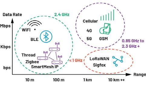
Figure 1 provides an overview of wireless standards, and Table 1 ranks selected wireless standards against key industrial requirements. It’s clear that BLE and SmartMesh (6LoWPAN over IEEE 802.15.4e) offer the best combination of low power consumption, reliability, and security
for industrial applications. Thread and Zigbee offer low power and secure mesh implementations but score lower on reliability.
Table 2 provides more details for the Zigbee/Thread, SmartMesh, and BLE mesh standards. SmartMesh includes a time synchronized channel hopping (TSCH) protocol, where all nodes in a network are synchronized and communication is orchestrated by a schedule. Time synchronization results in low power and channel hopping results in high reliability.
The BLE standard also includes channel hopping, but has some constraints in comparison to SmartMesh, including line powered routing nodes (increased system


cost and power), and TSCH is not supported. As previously mentioned, Zigbee/Thread score low on reliability and do not offer many advantages compared to BLE.
This article will focus on SmartMesh and BLE mesh as the most suitable wireless standards for industrial condition monitoring sensors.
sensors
Table 3 provides an overview of Analog Devices’ Voyager 3 Wireless Vibration Monitoring Platform and next-generation wireless condition monitoring sensors. Voyager 3 uses a SmartMesh module (LTP5901-IPC). An AI enabled vibration sensor (still in development) uses a BLE microcontroller (MAX32666). Both sensors include temperature and battery state of health (SOH) sensors. The Voyager 3 and AI version sensors use ADI MEMS accelerometers (ADXL356, ADXL359) to measure vibration amplitude and frequency for industrial equipment. Increasing vibration amplitudes and frequencies are identified using FFT spectra, which can indicate faults such as motor imbalance, misalignment, and damaged bearings.
Figure 2 provides an overview of a typical operation for Voyager 3 and the AI enabled vibration sensors. Like many industrial sensors, the duty cycle is 1%; most of the time
SOURCE: ANALOG
the sensor is in a low power mode. The sensor wakes up periodically for bulk data gathering (or in a high vibration amplitude shock event) or to send the user a status update. The user is typically notified with a flag to state that the monitored machine is in good health, and the user is given the opportunity to gather more data.
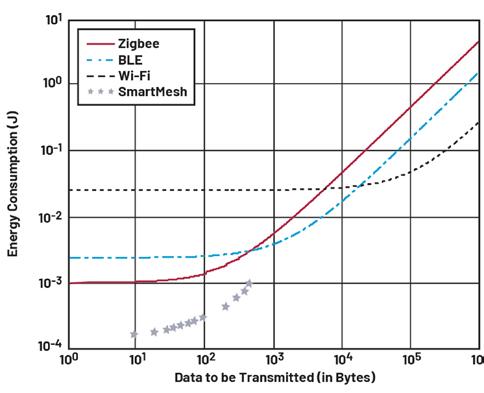
The sensors described in Table 3 operate on a 1% duty cycle, with Voyager 3 maximum payload of 90 bytes, and the AI version maximum payload of 510 bytes. Figure 4 (adapted from Shahzad and Oelmann3) shows that for 500 bytes to 1000 bytes, BLE consumes less energy compared to Zigbee and Wi-Fi. BLE is thus a good match for the AI enabled use case. SmartMesh provides ultra low power consumption, especially for payloads of 90 bytes or less (as used in the Voyager 3 sensor).
The SmartMesh energy consumption is estimated using the SmartMesh Power and Performance Estimator tool available on the website. The SmartMesh power estimator tool accuracy has been experimentally verified 87% to 99% accurate depending on whether a sensor is a routing or leaf node.
SmartMesh IP networks have several layers of security, which can be categorized as confidentiality, integrity, and authenticity.

A summary of SmartMesh security is provided in Figure 3. Confidentiality is achieved with AES-128-bit encryption end to end, even if there are multiple mesh nodes in the network. Data transmitted is protected by message authentication codes (message integrity check, or MIC) to ensure that it has not been tampered with. This protects against man in the middle (MITM) attacks, as shown in Figure 3. Multiple device authentication levels are possible, which prevents unauthorized sensors from being added to the system.
Devices operating with versions 4.0 and 4.1 of the BLE standard are security vulnerable, however, versions 4.2 and above include enhanced security (as described in Figure 3). ADI’s MAX32666 is compliant to the BLE standard 5.0.
This version introduces the P-256 Elliptic Curve Diffie-Hellman key exchange for pairing. In this protocol, the public keys of the two devices are used to establish a shared secret between the two devices, called the long-term key (LTK). This shared secret is used for authentication and generation of keys to encrypt all communication, protecting against MITM attacks.
In addition to radio transmit power consumption, one must consider the total system power budget and total cost of ownership. As described in Table 2, BLE and Zigbee both operate using a single gateway. However, both also require line power for routing nodes. This increases the power budget and total cost of system ownership. In contrast, SmartMesh routing nodes only require on average 50 µA of current, and an entire network can operate using a single gateway. SmartMesh is clearly a more energy efficient implementation.
As mentioned previously, SmartMesh uses TSCH, which has the following characteristics:
• All nodes in a network are synchronized.

• Communication is orchestrated by a communication schedule.
• Time synchronization results in low power.
• Channel hopping results in high reliability.
• The scheduled nature of communication brings a high level of determinism.
The synchronization accuracy is less than 15 µs across the entire network. This extremely high level of synchronization results in
extremely low power. On average 50 µA current draw, and 1.4 µA greater than 99% of the time.
Table 4 provides some key application challenges and how SmartMesh and BLE mesh meet these challenges.
SmartMesh performs better for dense networks with large numbers of nodes. Both BLE and SmartMesh perform well in dynamic industrial environments.
The reliability of SmartMesh was tested in


ADI’s wafer fab facility.
This is a harsh RF environment, with dense metal and concrete. Thirty-two wireless sensor nodes were distributed in a mesh network, with
four hops between the furthest sensor node to the gateway. Four data packets were sent every 30 seconds from each sensor node. Over a time period of 83 days 26,137,382 packets were
SOURCE: ANALOG DEVICES
sent from the sensors, with 26,137,381 packets received, resulting in 99.999996% reliability.
The next-generation wireless sensor includes the MAX78000 microcontroller with AI hardware accelerator. This AI hardware accelerator minimizes data movement and leverages parallelism for optimal energy use and throughput. Wireless industrial sensors currently available on the market typically operate on very low duty cycles. The user sets the sensor sleep duration, after which the sensor wakes up and measures temperature and vibration, and then sends the data over the radio back to the user’s data aggregator.
Commercially available sensors typically quote a 5-year battery life, based on one data capture every 24 hours, or one data capture every 4 hours. The next-generation sensor will operate in a similar fashion but take advantage of Edge AI anomaly detection to limit the use of the radio. When the sensor wakes up and measures data, the data is only sent back to the user if a vibration anomaly is detected. In this way the battery life can be increased by at least 20%.
For AI model training the sensor collects healthy data for the machine, which is then sent over the air to the user for AI model development. Using the MAX78000 tools the AI model is synthesized into C code, and then sent back to the wireless sensor and placed in memory.
SOURCE: ANALOG DEVICES
When the code is deployed the wireless sensor wakes up at predefined intervals, or in a high-g shock event. Data is gathered and an FFT is generated. From the FFT, the MAX78000 makes an inference based on this data. If no anomaly is detected the sensor goes back to sleep. If an anomaly is detected the user is notified. The user can then request FFT or raw time domain data for the measured anomaly, which can be used for fault classification.
This article provides an overview of wireless standards and assesses the suitability of BLE, SmartMesh (6LoWPAN over IEEE 802.15.4e), and Thread/Zigbee (IEEE 802.15.4) for use in industrial harsh RF environments. SmartMesh has superior reliability and low power operation compared to BLE and Thread/Zigbee. BLE can operate more reliably and at lower power compared to Zigbee and Thread for networks requiring 500 bytes to 1000 bytes of data transmission. Microcontrollers with embedded AI hardware accelerators provide a path to better decision-making and longer battery life for wireless sensor nodes.
Richard Anslow, Senior Manager, Analog Devices.
Visit Website
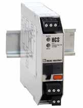
A HART Concentrator system accurately gathers digital level data from a transmitter along with giving the pulp and paper managers access to additional process variable data and critical diagnostic data. The HCS also converts the HART data directly to an industry-standard MODBUS RTU format that almost all industrial radios support.

STATE REGULATIONS REQUIRED A MAJOR PULP and paper company to monitor and record daily effluent water rates. This requirement was being fulfilled by sending an employee from their main control site to an remotely-located pond three times a day to manually record water levels. This process was inefficient, time-consuming and didn’t provide them with real-time data.
By installing a system utilizing technology from Moore Industries, the pulp and paper company implemented a system that is scalable for future installations while reducing employee workload and maintaining state regulatory compliance.
A leading pulp and paper company in the Pacific Northwest needed to monitor effluent
water flow as it drains into a remote pond at their facility. Because of a new government regulation, personnel had to drive a truck three times a day to the remote site, log the height of the water along with the date and time and return to the office. The company realized that this was not an efficient use of time and wanted to automate this process. This was done by calculating changes in water level in a V-neck weir entering in the pond and using this data to calculate flow rate.
Along with automating the collection of flow data, they also wanted this data to be displayed on an Ethernet based Human Machine Interface (HMI) panel in their boiler room. Moreover, since the data was required by the state, they needed to implement a historical collection and archiving system that allowed them to easily view historical data
and produce reports when required. Seeking a quick and efficient solution, the pulp and paper company turned to Autoline Controls, a full-service manufacturer’s representative of process instrumentation with an area of expertise in the pulp and paper industry.
Dale Stepper at Autoline Controls first suggested implementing a system at the pond site that utilized a HART radar level transmitter with precise measurement capabilities and a Moore Industries HCS HART® Concentrator System. The HCS is a HART to MODBUS RTU converter that serves as a HART master and polls the HART radar level transmitter to obtain its Primary Variable (PV) data – in this case water flow level.
Additionally, the HCS receives and converts to MODBUS RTU the level transmitter’s Secondary Variable (SV), Tertiary Variable
(TV) and Fourth Variable (FV) along with any diagnostic data.
There were two main reasons why Autoline Controls chose the HCS for this solution. First, the HCS accurately gathers the digital level data from the transmitter along with giving the pulp and paper managers access to additional process variable data and critical diagnostic data about the transmitter’s health and performance. The HCS also converts this HART data directly to an industry standard MODBUS RTU format, a serial communication standard that almost all industrial radios support.
The HART radar level transmitter has a front panel display for local viewing and connects to the HCS’s input via a 2-wire twisted pair cable. The radar gauge sensor measures the water height in the weir and publishes this data along with other process variable and diagnostic data to its internal HART memory location. This HART data is then polled by the HCS two to three times per second. The data is then mapped to a MODBUS memory map that resides in the HCS. This constant polling process ensures that data is continually updated on both the HART and MODBUS side of the HCS.
Using the HART radar transmitter connected to the HCS solved the problem of measuring the water level; the next step was transmitting this data to site operators. In this case, the data needed to go to an Ethernet based host
HMI panel and a historical collection system. There were no Ethernet networks, fiber lines or twisted pair wires available from the pond site to the control room so installing a local

SOURCE: MOORE INDUSTRIES
wireless network was chosen as the best method for acquiring these signals.
An initial wireless site survey was done using photos of the site. This showed potential problems in establishing a direct line of communications from the field site to the host system due to expected tree growth in the forest or accumulated snow on tree branches that may diminish the wireless radio’s signal strength. Since there was potential for future RF signal path attenuation, Autoline Controls recommended the following wireless components.
Moore Industries WNM Wireless Network Module radios. 900MHz FHSS (Frequency Hopping Spread Spectrum) radios were used instead of 2.4GHz models as its longer signal wave length tends to better penetrate foliage.
Ethernet versions of WNM radios were installed to meet the customer’s existing preference to utilize Ethernet communications throughout the facility. While the remote pond site previously had no communications links, using Ethernet communications at the pond site is a desirable forward step in extending the ability to add future assets with minimum added investment.
900MHz Yagi antennas were installed at both the boiler site and at the pond site with the narrow RF beams directed toward each other. After this was proven to be successful,


the boiler site antenna was changed to an omnidirectional antenna to enable expansion of the boiler site to communicate via wireless Ethernet with all locations of the facility.
Low-loss coax antenna cables with lightning arrestors were used.
The last piece of the solution involved delivering the level transmitter’s signals to their host system in a manner that met their total requirements. The site operators expressed a desire for the level transmitter’s data to be represented by both digital and analog signals.
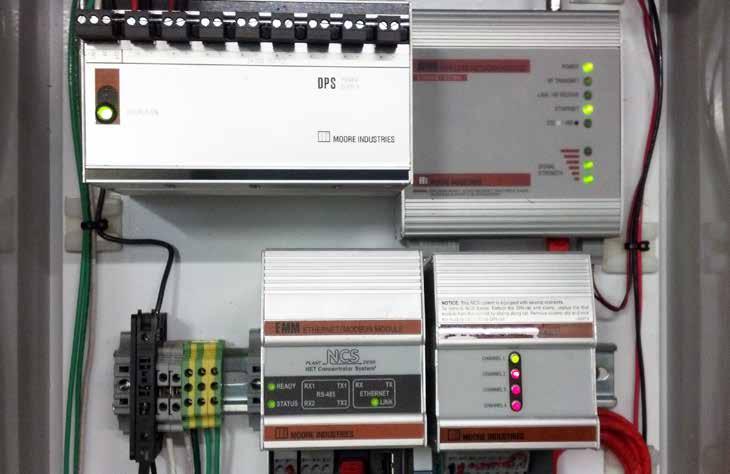
While this could get quite expensive with traditional PLC or DCS solutions, Autoline Controls recommended adding a small Moore Industries NCS NET Concentrator System® to the host site. The NCS is a dynamic I/O system that can act as an expandable I/O system, MODBUS RTU master, MODBUS RTU slave or MODBUS/TCP slave. The NCS also provides a myriad of math and logic solutions through its ISaGRAF embedded control and logic program.
The heart of the NCS system is the Ethernet/ MODBUS Module (EMM), which is essentially the NCS’ CPU and communications center. The EMM takes on various roles in this application. It first acts as the MODBUS RTU master and polls the HCS at the pond site through the serial port of the WNM radio. The MODBUS RTU data collected from the HCS contains the HART


HART flow level measurements at the pond site were converted to MODBUS RTU by a HCS HART Concentrator System and sent from a WNM Wireless Network Module at the pond to a receiver radio at the boiler control room. The information was relayed from the wireless radio to an HMI display and DCS/Historian by the NCS NET Concentrator System.
data from the level transmitter and is then placed into the EMM’s local memory map. Here it is stored as MODBUS RTU and MODBUS/TCP compliant registers.
The EMM is polled as a MODBUS/TCP slave by the Ethernet-based HMI at the boiler room so that site operations can view the level and diagnostic data. The EMM is then programmed with ISaGRAF logic to assign process variables to the NCS' Analog Output Module. The AOM provides up to four 4-20mA or voltage signals (ranges from 0-10 volts) that can be taken to any analog receiving device, such as a historical data collection system.
Ensuring a full-time communication link with the pond site was also a latent request by site operations. Therefore, a simple watchdog routine residing in the EMM was written in ISaGRAF to monitor the wireless connection and instruct the MODBUS RTU, MODBUS/TCP and 4-20mA values from the AOM module to go to pre-defined limits if there is a wireless link failure to the EMM.
This allows site operations at the boiler room to immediately tell when the wireless communication link has failed. Once the link is re-established the system automatically picks up where it left off, transmitting and making real-time process variables and diagnostic data from the level transmitter available.
Moore Industries assisted Autoline Controls in expediting the installation. Moore Industries application engineers pre-configured the electronics and bench tested the solution using a similar radar level transmitter kept at Moore Industries' headquarters for such customer applications. This allowed Autoline Controls to install the system quickly and have confidence that it would work with minimal adjustments needed.
The system is now enabling the pulp and paper company to efficiently get accurate and required readings on the levels in their effluent water system.
"Part of their license with the state required them to send an employee to the site to write down numbers three times a day, seven days a week," Stepper said. "That's essentially one-half of the work of a full-time employee -- including having to work weekend. This system automates their formal measurement and documentation requirement process and lets their employees focus on other critical aspects of their operation.
Case study by Moore Industries.
Artificial intelligence (AI), edge computing and industrial cybersecurity are just some of the technology megatrends that are driving the latest innovations in Industrial Ethernet solutions. Read how industry experts view the newest trends, unique capabilities and the latest solutions for smart manufacturing.

INDUSTRIAL ETHERNET SOLUTIONS FOR SMART manufacturing continue to leverage a range of computer and networking technology megatrends. Artificial intelligence, edge computing and networking are just some of the mainstream technologies that Industrial Ethernet solutions are leveraging.
For this special report, the Industrial Ethernet Book reached out to Jessica Forguites, Network Infrastructure Platform Lead for Rockwell Automation and Casca Kwok, Technical Marketing Engineer for Cisco Systems in a Question and Answer (Q&A) format.
Here is what they had to say about the megatrends shaping the future of enterprise and machine control networking. The conversation covers unique benefits and capabilities, impact on factory automation applications and future challenges.
Industrial Ethernet Q&A
Accelerating the cycles of innovation.
What key trends and networking technology is impacting the stateof-the-art in factory automation and process control?
Kwok/Cisco response
Edge computing, cybersecurity, and AI network analytics are some of the key trends impacting factory automation and process control applications. Networking and communications technologies are key enablers for these trends.
Edge computing shifts data processing from centralized data centers to the local production floor. This localized processing approach reduces network latency and
jitter, enabling real-time data processing and immediate responses to machine data. This capability optimizes manufacturing operations and enables real-time quality control.
Cybersecurity solutions protect critical industrial control systems from attacks and safeguard confidential data from unauthorized access. As factories increasingly connect previously unconnected sensors and machinery to the network to collect data for operation insights, implementing unified security measures ensures operational continuity. One trend is the deployment of pervasive network access policies such as zero-trust architectures, which operate on the principle that no device should be automatically trusted, regardless of whether it is within or outside the network.

“Networking technology has advanced to support faster and more reliable data exchange between machines and systems. This enables AI systems to collect and analyze more data, leading to improved predictive maintenance strategies, quality controls and operational efficiencies.” -- Jessica Forguites, Network Infrastructure Platform Lead, Rockwell Automation.
AI network analytics leverages machine learning and reasoning to provide actionable insights for industrial ethernet deployment for optimizing uptime. It plays a key role in detecting unusual patterns that may indicate issues, and predicting capacity trends before the exhaustion of resources disrupts production.
Forguites/Rockwell response
Trend 1 - Artificial Intelligence: Networking technology has advanced to support faster and more reliable data exchange between machines and systems. This enables AI systems to collect and analyze more data, leading to improved predictive maintenance strategies, quality controls and operational efficiencies.
Trend 2 - Edge Computing: Data processing closer to the source of data generation enables lower latencies and quicker decisions. Capturing OT data with context at the edge can help unlock high-quality and actionable insights from the immense volume of plantfloor data.
Trend 3 - Building Cyber-Resilience: Advancements that enable adding security extensions to communications protocols to protect data from eavesdropping and tampering are being extended to Industrial Communication protocols (CIP Security). In addition, modern networking technologies support improved network segmentation and enable users to isolate critical systems. By creating isolated network segments, manufacturers can limit the spread of potential cyber-attacks and contain damage of a potential attack.
Trend 4 - Empowering the Workforce: Advancements in networking support additional automation of repetitive tasks, allowing workers to focus on more complex value-added activities. Increased mobility is enabled through evolutions in both Wi-Fi 6 and Cellular (5G) technologies. This gives users the flexibility to perform tasks and communicate without being tethered to a specific location.
What technological benefits and unique capabilities do these solutions offer?
Kwok/Cisco response
Edge computing offers low latency and high-speed connections for real-time applications, enabling the implementation of advanced technologies such as artificial intelligence and machine learning at the edge. Manufacturing processes can leverage real-time data for analytics, pattern detection, and predictive decision-making. Cybersecurity solutions protect digital and OT assets. Effective network segmentation and access control mechanisms reduce the attack surface and prevent the lateral movement of threats. Encryption ensures data remains secure and unreadable to unauthorized users. Cybersecurity solutions support incident response and recovery capabilities to help quickly respond to and recover from cyber incidents. Security Information and Event Management (SIEM) correlates and analyzes security event data sources from different machine manufacturers, providing a comprehensive view of security posture.
AI network analytics reduce downtime by continuously monitoring network behavior and identifying and issues that could lead to or have led to failures. This is crucial in an era where cybersecurity threats have become more sophisticated and damaging. AI-enhanced systems can adapt to new threats, providing a dynamic defense mechanism that evolves as new security challenges emerge.
Forguites/Rockwell response
Solutions that enable faster and more reliable data exchanges include gigabit port speeds, higher speed Wi-Fi 6 and 5G cellular communications, and automation equipment that essentially creates a larger pathway (bandwidth) for communications to travel. In addition, technologies like PRP (Parallel redundancy protocol) enable fully redundant network communications to meet the reliability needs of critical operations.
Edge computing offers many benefits, including cost efficiency, by reducing the amount of data that must traverse WAN networks and be stored in large-scale storage locations. This reduces latency and enables quicker decisions by capturing data closer to the source of data generation.
Network segmentation and isolation of critical systems provides benefits like reduced attack surface. This enables more effective containment strategies for cyberattacks and simplified compliance with regulatory requirements that demand isolation of critical systems and data. The last point here is cost efficiency, as physical isolation can be expensive because additional hardware is

often required to translate communications across these physical boundaries to meet modern manufacturing requirements.
Benefits of secure protocols for industrial use cases include extending traditional IT cybersecurity protections to factory automation assets. Ensuring data integrity and compliance with industry standards is another benefit because industrial applications can self-defend from unauthorized communications.
How is Industrial Ethernet advancing the solutions used in machine and process control?
Kwok/Cisco response
Industrial Ethernet advances solutions used in machine and process control with enhanced scalability, interoperability between different systems, high-speed data transfer, and reliable communications.
One of the benefits Industrial Ethernet offers is its ability to scale operations and make them more flexible. Network and compute resources can be easily expanded as a plant or facility grows. This flexibility enables manufacturers to adapt to changing production demands and incorporate modern technologies.
Another significant advantage is interoperability. Industrial Ethernet supports a diverse range of protocols and standards, enabling communication across devices and systems from different manufacturers.
Industrial Ethernet networks are built for reliability and redundancy. These
networks provide fault tolerance, feature fast converging ring topologies and parallel networks to ensure continuous operation. Some of these tailor-made protocols could achieve zero packet loss during network failures, thereby maintaining uptime in critical industrial processes.
Industrial Ethernet improves data security and enhances OT asset visibility and transparency. Solutions such as Cisco Cyber Vision can detect and identify OT assets from different vendors, continuously monitor machine communication patterns, spot asset vulnerabilities, and track control systems events and device modifications. Having a holistic visibility of the OT network enables anomaly detection and helps minimize unplanned downtime.
Forguites/Rockwell response
Industrial Ethernet has been advancing solutions used in machine and process control for many years. The consistent foundational standards of Ethernet have led to more use of technology advancements throughout the machine and process control industry, which helps future-proof the industry as well.
Seamless integration of a diverse set of equipment needed to meet application needs is another advantage of Ethernet. This is never truer than today as we think about emerging “device” categories that need to be integrated into machine and process control applications (e.g., AMRs, edge computing devices, digital twins, smart sensors).
Networks that are unified without
sacrificing segmentation and isolation enable IT and OT network integration for better data flow, decision making and visibility to diagnostics to quickly resolve networkrelated issues.
Advancements and best practices for securing Ethernet-based systems extend to machine and process control applications (e.g., secure communications protocols and network segmentation best practices).
What types of applications are leveraging the use of advanced networking in manufacturing?
Kwok/Cisco response
Advanced networking technologies are being leveraged across manufacturing processes that require high precision and minimal downtime. These applications include manufacturing equipment, robotic systems, visual inspection systems that constantly adjust to changes in production line parameters.
These technologies require high-speed, low-latency networks, real-time data processing for decision-making. For instance, visual inspection systems use high-resolution cameras to inspect products on the assembly line, identify defects before items proceed to the next stage of production.
Digital twins are another typical use. Digital twins create a virtual clone of OT assets and processes, enabling manufacturers to simulate and predict behaviors. This requires an advanced network to handle the constant data stream generated from sensors

and machines.
The trend of hybrid work models in manufacturing has also driven the need for secure, remote access to manufacturing processes. Plant managers and supply chain partners require seamless and secure access to processes from remote locations. Advanced networking solutions provide the necessary infrastructure to ensure that remote access is both secure and efficient. This is particularly important in a decentralized manufacturing environment where operations are spread across multiple locations.
Forguites/Rockwell response
Many applications and industries are leveraging advancements in networking. One example is material handling and logistics. These applications have massive scale, requiring scalability of Ethernet for a costeffective solution. In addition, advancements in wireless technologies enable real time tracking and coordination of automated guided vehicles (AGVs).
Modular production systems are increasingly used in the pharmaceutical, food and beverage and automotive industries. Advancements in network technology enhance the agility, efficiency and security needed for small batch production, which helps manufacturers meet the growing demand for customized and specialized products.
Energy management systems is another application that crosses many industries as manufacturers look to respond to regulatory requirements and achieve sustainability goals They use Ethernet-connected sensors,
meters and control systems to optimize energy usage and optimize costs.
What challenges that automation engineers face does Industrial Ethernet machine connectivity address?
Kwok/Cisco response
One of the challenges is the integration of hybrid systems and devices. In many manufacturing environments, machinery and equipment come from different vendors, each using different communication protocols and mechanisms. This lack of standardization can make it difficult for industrial automation to interoperate between devices. Industrial Ethernet provides a solution to address this problem.
Industrial environments demand high system availability and reliability to minimize downtime and maintain continuous operations. Industrial networks must be designed in a way that can sustain harsh conditions and provide redundancy to prevent failures. Industrial Ethernet solutions, such as the Cisco Catalyst Industrial Ethernet switches, offer features such as ring topologies which are designed for industrial settings and highly resilient protocols that achieve lossless failover. These technologies ensure that if a network component fails, communication can be quickly resumed to maintain operation availability.
Security and compliance with standards and regulations are significant concerns for industrial automation engineers, especially
with the increasing connectivity of sensors and machines to industrial systems. Advances in industrial Ethernet connectivity incorporate end-to-end security measures to protect against these threats, visualize ISA/IEC62443 zones and conduits, and dynamically segment networks based on the device profiles.
Forguites/Rockwell response
Some challenges here include:
Accounting for the expected growth of data needs: As the needs are expected to expand with the use of technology like AI for example, the high bandwidth support that comes with Ethernet is a necessity.
Legacy system integration: Because Ethernet leverages common standards at its foundation, it reduces the need for specific gateways. In addition, support for protocol converters and gateways from other technologies to Ethernet are readily available to ensure upgrades can be executed in stages.
Addressing cyber security threats: Secure industrial protocols and network segmentation enables the built-in capability to harden the automation system communications. Support for encryption of data and authentication and integrity reduces the attack surface and results in more effective containment of an incident. Meeting network reliability and uptime requirements for critical systems: Features like PRP (parallel redundancy protocol) and redundant ring topologies (device level rings) ensure high network reliability for continuous operations.
Al Presher, Editor, Industrial Ethernet Book.
The only publication worldwide dedicated to Industrial Ethernet Networking and the IIoT. Visit iebmedia.com for latest updates.

New website offers deepest, richest archive of Industrial Ethernet and IIoT content on the web.


View and/or download latest issue of Industrial Ethernet Book and past issues.
Search our database for in-depth technical articles on industrial networking.
Learn what's trending from 5G and TSN, to Single Pair Ethernet and more.
Keep up-to-date with new product introductions and industry news.
Tucker Energy Services set out on a development program to replace an aging data acquisition system, improve their limited visibility and data sharing, reduce their dependence on third-party solutions and eliminate inaccurate/nonexistent level sensing in fluid tanks.
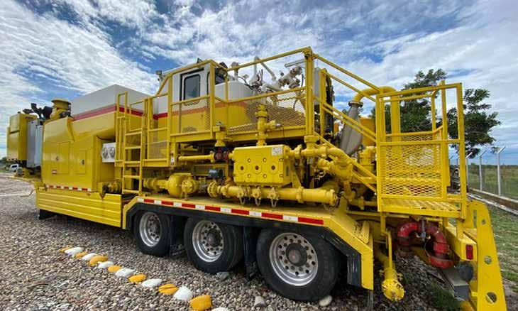
TUCKER ENERGY SERVICES (TES), BASED IN the twin island nation Trinidad and Tobago, provides specialty services for the Oil and Gas industry. With a focus on enhancing oil well integrity and efficiency, they offer customers:
• Well cementing, which involves sealing wellbores and securing casings in oil and gas wells—prevents the migration of fluids between underground formations and supports the well casing, ensuring the structural integrity and isolation of the wellbore.
• Coiled tubing , a continuous length of flexible steel tubing that can be wound onto a large reel—helps speed up processes like pumping services and well cleanouts.
• High pressure pumping, using pumps to inject fluids at high pressures into oil wells—helps to stimulate production. TES also offers wireline and mud logging services as well as operates their own Liquid
Mud Plant, a specialized facility designed for the preparation, storage, and maintenance of drilling mud—a crucial component in drilling operations. The facility helps TES ensure a consistent supply of customized drilling fluids while their comprehensive services support the operational success of oil and gas customers in the region.
In 2019, TES found their operations hindered by outdated equipment and an insufficient ability to manage data. The company identified four critical areas needing improvement:
Aging data acquisition system: The existing setup was over a decade old and could not be adapted to new technologies or integrated with modern data management practices.
Limited visibility and data sharing: The legacy system's lack of Ethernet connectivity restricted data access to local operators only,
preventing efficient remote monitoring and decision making.
Dependence on third-party solutions: Previously implemented systems from external providers offered little room for customization or expansion without incurring exorbitant costs.
Inaccurate/nonexistent level sensing in fluid tanks: Only 8 of the 150 tanks had level sensing capabilities, and those in place used mechanical level switches, which were prone to failures that led to unreliable readings and potential costly spills.
Costs, controls and learning curves
Navin Singh, Electrical & Instrumentation Supervisor at Tucker Energy Services, knew that a technology upgrade would increase reliability and improve visibility, so he began researching. The investigation led Singh into quite the dilemma.
Ready-made systems for tank monitoring
and data acquisition came with steep price tags, significantly inflating the budget. Furthermore, maintenance and updates for these systems would require TES to rely on third-party integrators, which limited control over their system and further added to their costs—necessitating ongoing expenses for external engineering support.
The other option was for Singh to select commercially available controls equipment to develop a homegrown system. But the team at TES had minimal exposure to Programmable Logic Controllers (PLCs), so adopting new technology would be a steep learning curve. To pull this off, Singh would need a user-friendly product with learning tools that wouldn't break the bank.
The move to groov
“We had a supplier who used Opto 22 systems with PAC Control programming software, and we heard they were able to develop their own data acquisition system,” Singh recalled. “We wanted to have full control of the hardware and software development.”
“I heard about this new groov EPIC system, and the information on YouTube excited me— showing what it could potentially do. It was quite reassuring that when I initially made
contact, I was able to speak directly to an engineer [Opto 22 Application Engineering Specialist, Selam Shimelash],” said Singh.
Other data acquisition systems that Singh was exploring— from both the U.S. and the UK—didn’t quite fit the mold he was

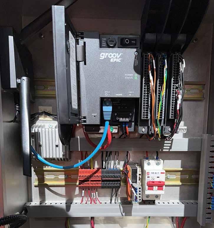
looking for. The groov EPIC system, an Edge Programmable Industrial Controller from Opto 22, however, provided real-time control, connectivity, and data visualization all in one platform.
“For making future improvements, with groov, we are in full control. And with no software development fees or annual licensing fees, we can keep adding and improving while keeping costs down,” Singh said.
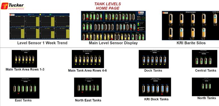
TES started by integrating seven groov EPIC systems—processor, power supply, chassis, and I/O— to monitor tank levels for their 150 tanks. Each groov EPIC is placed in a strategic location near a group of tanks to avoid long cable runs.
An eighth groov EPIC system is installed in their main office and displays an aggregated view of all 150 tanks on a single heads-up display.
Using the EPIC’s native HDMI output, Singh paired each EPIC with a cost-effective Winmate® monitor to provide local views for operators. The monitor displays the free groov View™ visualization software that is preloaded on every EPIC system.
For help building his screens, Singh utilized Opto 22’s free SVG Image Library.
For additional data acquisition, TES uses a variety of groov input modules, from traditional analog to specialized frequency input modules, part number GRV-IDCIFQ-12, for measuring pumping rates and calculating the volume of fluid being moved.
Later in the project, Singh implemented digital output modules to sound the alarm and prevent potential overflows and spillage—a huge savings since drilling mud and other related fluids are expensive, cleanup costs are high, and the environmental impact of spills can be devastating.
With Singh’s newfound proficiency in PAC Control, he took advantage of the file creation and writing tools to log tank level and production data to a .CSV file that could be opened and manipulated as a spreadsheet.
Soon thereafter, he discovered something new on Opto 22’s YouTube channel—Node-RED opened the door to a more sophisticated possibility: SQL data logging. “All the data is now recorded and sent to a MSSQL database,” he noted.
As Node-RED proficiency ramped up, Singh was tasked with another challenge: establishing outbound communication from his groov EPIC systems using WITS Level 0—a standard for real-time data exchange in the Oil and Gas sector. Despite modern advances in Ethernet, WITS Level 0 still uses serial communication to exchange ASCII data between drilling equipment and monitoring
systems.
Using Opto 22’s GRV-EPIC-CSERI-4 module for serial data transmission, Singh found a Node-RED flow in the open-source community that supported the specialized protocol, and in a short amount of time, he was able to deliver the serial data to their customer, a local oil company, in the specialized format they required.
Tucker Energy Services has realized significant operational improvements since implementing their new tank monitoring and data acquisition systems. In fact, future enhancements are already in discussion:
Tank monitoring , with radar level sensors and alarms, has drastically reduced spillage risks associated with expensive drilling mud and related fluids. TES is already beginning the next phase of this project, which will include automatic shutdown of pumps to prevent overflow and automated emails with existing tank levels every 12 hours.
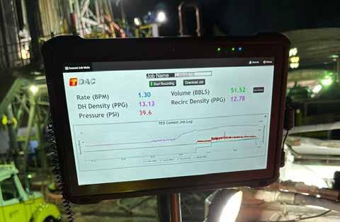
groov View HMIs have improved visibility and empowered operators, who are now able to choose among different specialized screens depending on the type of job. For example, a cementing operator is more interested in fluid density and pumping rates while high-pressure pumping operators are interested in real-time pressure readings. Having the right information at their fingertips empowers operators to make better decisions and prevent mistakes.
Data acquisition with groov EPIC systems using Node-RED writing data to MSSQL is in its early stages.
Singh estimates the cost of this system is
about one third of what a turnkey solution would have been. And as full, rich data begins to fill their database, TES will gain more valuable insights into their daily operations.
Upper management has been delighted that without a PLC programmer on staff, Singh and his team have been able to build a custom system at a fraction of the cost for a turnkey solution. “We have upcoming meetings with management, and we expect all future applications to be based on Opto 22 groov devices,” Singh affirms.
And the cherry on top? In a recent audit, a large oil and gas conglomerate visited TES to view their fluid, which is stored on TES’ site in some of the newly instrumented tanks.
The customer was quite pleased with the significant improvement in their monitoring and data acquisition systems.
Singh’s final comments for others considering this type of project, “Troubleshooting is a different mindset from programming. Watch some of the YouTube videos and do some of the online training, especially if you are new to programming.”
When asked to describe his experience working with engineers at Opto 22 he remarked, “Very refreshing and great!”
Case study by Opto 22.
Learn More
Concurrent Connections do not solve all the problems of systems that require high availability, but they are an important building block of such systems. Concurrent Connections provides a standardized communication protocol that helps enable high availability systems.

IN MOST PROCESS CONTROL AND MANY manufacturing applications, control system failure resulting in unexpected shutdown can cause financial loss through wasted products and system restart can take an extended period of time. The ability to design faulttolerant control systems for these applications is critical.
This is even more important when the response to a safety-critical incident requires a highly controlled transition to a safe state, rather than the instant stop of moving equipment normally used in manufacturing applications. These applications rely on the control system being “highly available” even in the face of unexpected failures. Products can be designed to minimize failures, but not eliminate them.
Systems can employ redundancy to remove the chance of a single failure rendering the control system inoperable. Both techniques help, but still have limitations.
In the Spring 2023 publication of the CIP family of specifications, ODVA announced the addition of an important new technology,
Concurrent Connections which enables flexible, zero switchover time, end-to- end redundancy solutions. This paper provides a brief introduction to how availability is measured, documents some of the issues with current high availability solutions, and highlights how Concurrent Connections address them. It will also summarize the portions of the CIP specifications that were modified to add this new functionality.
Availability in the context of industrial automation systems refers to the ability of the system to perform its intended functions as expected for a specified period of time. Availability is expressed as a percentage of the total operating time of the system. Availability is calculated with the following formula:
Availability = MTTF / (MTTF+MTTR) where:
MTTF is Mean Time To Failure. MTTF is the average time that a system can provide service before experiencing a failure. MTTF for the
system is calculated based on the MTTF of its components. MTTF of a single module is provided by its vendor and is calculated based on the specification of parts used to build a module, the module design, and the number of module warranty returns after one year.
MTTR is Mean Time To Restore/Repair. MTTR is the average time it takes to resume system service after a failure has been experienced. MTTR includes the time it takes to detect the failure. The value of MTTR depends on many factors and is specific to the system, this value is provided by the system constructor.
High availability is based on the concept of availability. High Availability is the term used to describe a higher amount of availability for the system than standard availability. High availability is often expressed as a "number of nines". See the table on the top of page 37. High Availability can be achieved by maximizing MTTF and minimizing MTTR. Maximizing MTTF for a single module can be achieved by using high-quality components
that have proven reliability and are designed to withstand the specific operating conditions of the industrial automation system. Maximizing the MTTF of a single module has its technological limits.
Maximizing the MTTF of the system is achieved by applying redundancy to system components. In order to minimize MTTR, the failure needs to be detected as quickly as possible and repaired as quickly as possible. Low MTTR is achieved by reliable diagnostics, training of the system maintenance staff on the repair procedure, and availability of spare system components.
Redundancy in the context of industrial automation systems refers to the use of duplicated components that are designed to provide backup support and mitigate the failure or reduce the consequences of a failure. There are multiple aspects of redundancy:
• Backup type: Hot, Warm, or Cold
• Hot. The backup is completely ready to take over when the active device fails.
• Warm. The backup is powered up but requires an action to be activated.
• Cold. The backup is not powered up.
• Synchronization. Active or Passive
• Active. The backup is kept in a synchronized state with the active device.
• Passive. The backup is not synchronized with the active device.
• Switchover or Concurrent
• Switchover. Only the active device is actively participating in the process, the backup device will be activated when the active device fails.
• Concurrent. The devices that are redundant are functionally equivalent and simultaneously participate in the process, they are all backups of each other.
Fault Tolerance in the context of industrial automation systems is the ability of the system to continue its intended operations in the presence of failures. Redundancy
is one way to achieve or increase Fault Tolerance.
The system can be designed to have fault tolerance in a selected part of the system. System parts are:
• Controllers
• Power supplies
• Network Infrastructure
• IO devices
• Field devices
It is up to the system constructor to choose where to apply redundancy and where to achieve fault tolerance. A system that supports fault tolerance for every device within the system is deemed a “no single point of failure” system.
An example of a technology that can tolerate failure in the system is Device Level Ring (DLR). A system that uses DLR can continue its operations in the presence of a single fault of network media (cable) that connects devices in the ring.
Another example of technology designed for fault tolerance is Parallel Redundancy Protocol (PRP). A system that uses PRP can continue its operations in the presence of multiple failures of network media so long as one path through the network remains available between participants in the connection.
High availability in process industry
The term “Process Industry” encompasses many different industries. Examples of process industries are:
• Power generation (production of electricity through various methods, such as coal or gas-fired power plants and nuclear power plants)
• Oil and gas (exploration, production, refining, and transportation of oil and gas)
• Mining and minerals (extraction and processing of minerals, such as coal, metals, and industrial minerals)
• Food and beverage (production of food and beverage products, such as baked goods, soft drinks, and processed foods)
• Pharmaceuticals
• Chemical manufacturing
• Pulp and paper (production of paper products, such as newspapers, magazines, and packaging materials)
• Textile manufacturing (production of textiles and clothing, such as cotton, wool, and synthetic fibers)
• Cement manufacturing
• Water treatment (treatment of water to remove impurities and make it safe for consumption or industrial use)
• Semiconductor manufacturing
• Paints and coatings manufacturing
• Glass manufacturing
The common characteristics of process industries are that they involve the production of physical and/or chemical products through a series of continuous or batch processes. Process industries installations are usually large-scale and complex, and they transform high volumes of materials. Processes may involve high temperatures, high pressures, and other hazardous conditions, which can make it difficult, risky, or even impossible to stop the process abruptly.
Those processes often involve the use of raw materials, which cannot be easily stored or reused once the process has been stopped. For example, in the oil and gas industry, oil and gas reserves cannot be easily shut down and restarted, and the reservoirs may be damaged if the process is abruptly stopped or restarted. Similarly, in the chemical industry, stopping a reaction process prematurely can result in the loss of valuable raw materials and products. Another example is glass production, when the glass melting process begins it is typically operated continuously for several years to maintain the high temperatures required for the melting process. Stopping such a process quickly can damage the process equipment or the glass product.
The sudden stoppage or the loss of control of an industrial process can have catastrophic consequences, including loss of human lives, environmental contamination, equipment damage, also significant economic implications, such as lost productivity, lost profits, and increased costs associated with restarting the process.
A few examples of catastrophic incidents in the process industry:
Bhopal gas tragedy, 1984, Bhopal, Madhya Pradesh, India. The toxic gas (methyl isocyanate) leak at a Union Carbide India Limited pesticide plant caused the deaths
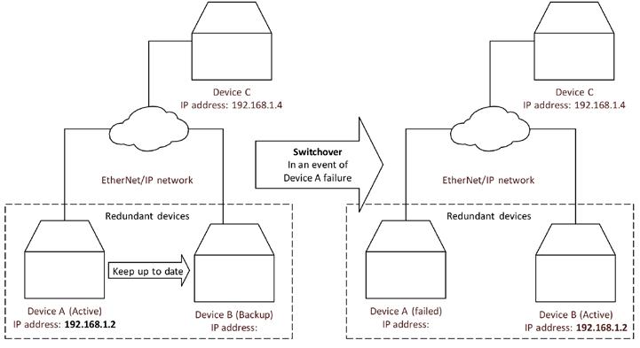
of an estimated 3,000 people immediately, and an additional 15,000 deaths in the years following the incident. Over 500,000 people were injured.
Piper Alpha oil rig explosion, 1988, Piper Alpha oil rig in the North Sea. An explosion resulted in the deaths of 167 workers and caused significant damage to the environment. The total insured loss was about 2 billion US dollars (1988). At the time of the disaster, the platform accounted for approximately 10% of North Sea oil and gas production.
Deepwater Horizon oil spill, 2010, Gulf of Mexico. The oil rig explosion caused the loss of 11 lives and an oil spill that resulted in significant environmental damage.
Tianjin explosions, 2015, Tianjin, China. An explosion at a chemical storage facility caused the deaths of 173 people, injured hundreds more, and caused significant damage to the surrounding area.
Because of the severe consequences of industrial process failure, the process industries are highly regulated.
High Availability is critical to the process industry for the following reasons:
• Safety: High Availability can help prevent accidents and protect workers from harm.
• Productivity: High Availability minimizes process downtime.
• Company reputation: The severe consequences of industrial process accidents can have a significant impact on a company's reputation. High Availability can help prevent accidents.
• Cost savings: High Availability can help
prevent accidents and thus minimize the need for damaged equipment repairs and replacements.
The CIP Networks Library currently contains some solutions for high availability and redundancy. These solutions do not cover the whole system and are missing some details, leading vendors to create vendor- specific solutions.
CIP Networks Library, Volume 1 Common Industrial Protocol defines a Redundant Owner connection type that enables multiple Controllers to take ownership of a device’s outputs in a standardized way. The solution involves the use of the Redundant Owner bit in Network Connection Parameters of the Forward_Open request and Claim Output Ownership (COO) and Ready for Ownership of Outputs (ROO) bits in the connection real-time header. This solution does not address the redundancy of connection targets.
The Redundant Owner and ROO, COO solution for redundancy was popular for ControlNet devices but this popularity did not transfer to EtherNet/IP devices.
CIP Networks Library, Volume 2 EtherNet/ IP Adaptation of CIP defines ways to achieve media redundancy using Device Level Ring (DLR) and Parallel Redundancy Protocol (PRP).
CIP Networks Library, Volume 4 ControlNet Adaptation of CIP [11] defines ways to achieve media redundancy and ring topologies.
Existing redundancy solutions and their problems
Despite limited support for redundancy in the CIP Networks Library, vendor-specific redundancy solutions based on CIP are available in the market. On the one hand, there is a need to standardize the redundancy scheme to support the seamless integration of devices that support redundancy from different vendors. On the other hand, redundancy is used for critical missions, and in order to minimize the risk of failure vendors tend to release “redundancy bundles” that gather a specific set of devices in specific versions, and only guarantee proper redundancy system behavior for the “redundancy bundle”.
One example vendor-specific, CIP-based redundancy solution takes advantage of the flexibility of EtherNet/IP networks. The family of TCP, UDP, IP, and Ethernet protocols is used as an abstraction to enable a backup controller to take over the responsibilities of the active controller in the event of active device’s failure. The active device has an IP address and MAC address that identify it in an EtherNet/IP network and that are used to communicate with the rest of the system. The transfer of responsibilities to the backup device is known as switchover or failover. During the switchover process, the backup device takes over the IP address of the failed device and sends Gratuitous ARPs to announce that this IP address is now associated with a new MAC address. The backup device continues the work of the active device that has failed as shown in Figure 1.
The solution described in Figure 1 is an example of switchover redundancy. The solution described above has pros and cons. The pros are:
Not all the devices connected to EtherNet/ IP networks need to support redundancy. Parts of the system can even be unaware that redundancy is used in another part of the system. This supports easy redundancy solution integration with any EtherNet/IP capable devices.
When combined with Hot and Active aspects of redundancy, this solution is capable of maintaining CIP implicit connections if the switchover can be executed before the connection timeout timers of those connections expire.
The cons are as follows:
During the switchover there is a nonzero period of time when CIP implicit connection data is not sent by any of the redundant devices. The process is not controlled for this period of time.
The switchover time constrains values of CIP connection parameters. The Requested Packet Interval (RPI) and Connection Timeout Multiplier values must be adjusted, so the connection does not time out during the switchover period. The connection timeout settings are especially important for CIP Safety connections as the timeout of such connection would cause the system to transition into a safe state, and this would be a “spurious trip”. Long connection timeout settings are unacceptable for customers that want both redundancy and quick detection of connection problems.
The switchover times that can be guaranteed with this technique are too long for some systems. For safety systems, a long switchover time means a long safety reaction time that can impact the physical constraints of a system in order to keep humans and equipment safe. Long safety reaction times can even make the system infeasible if it cannot be out of control for that period of time.
For every CIP connection maintained by the active device, the O->T Network Connection ID and T->O Network Connection ID need to be passed from the active device to the backup device to enable switchover without dropping CIP connections.
CIP Explicit connections are TCP-based in EtherNet/IP and synchronizing TCP sessions between the active device and the backup devices is challenging, thus usually CIP Explicit connections are dropped at switchover. This leads to a loss of communication with HMI devices and the need for reconnection.
This redundancy technique only applies to EtherNet/IP originators.
Another approach that some targets have used is to delay applying their connection fault action for a configurable amount of time after a connection times out. If another

(or even the same) originator re- establishes the connection before this additional delay expires, the connection fault action is avoided. The pause in control during the additional delay required for this approach is not acceptable for all applications.
The spring 2023 publication of the CIP Networks Library introduced Concurrent Connections technology. Concurrent Connections are an answer to many of the redundancy solution deficiencies identified above. In short, Concurrent Connections enable flexible, zero switchover time, end-to-end redundancy solutions. The easiest way to explain Concurrent Connections is to compare them to PRP. Concurrent Connections are like PRP on the CIP connection layer. Concurrent Connections allow the use of redundancy for any endpoints or routers along the path of the connection. Concurrent Connections enable multiple paths for transferring the CIP data
between all participants in the connection. The CIP data is sent simultaneously across multiple branches through all of the participants to reach the other end of a connection as shown in Figure 2.
There are three redundant devices in the above diagram: a duplex originator, a duplex router, and a duplex target. The concurrent connection is represented as all the links between all participants in the above diagram. There are 8 such links, the CIP specification calls them branches of the concurrent connection. Because of this concurrent connection topology, there are multiple paths that data from either of the originator participants can use to reach either of the target participants and vice versa. All of the concurrent connection branches together form one logical CIP Application Connection. From the application perspective, the concurrent connection looks exactly the same as the non-concurrent connection.
If a device participating in the concurrent connection fails, then its concurrent
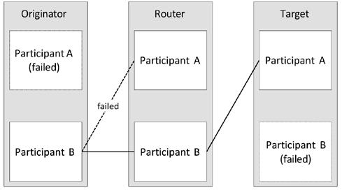

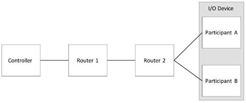
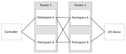
connection branches will stop working. When the network path used by the concurrent connection fails, the affected concurrent connection branches will stop working. The remaining branches of the concurrent connection will keep on delivering data between originators and targets as long as there is at least one available path between originators and targets. Figure 3 demonstrates the setup from Figure 2 after a few failures.
Originator Participant A and Target Participant B have failed and are unavailable. There are no concurrent connection branches from those devices. Also, the network path between Originator Participant B and Router Participant A failed.
The concurrent connection branches
between Router Participant A and targets have timed out as Router Participant A is not able to route toward originators. Despite multiple failures, the concurrent connection is still able to exchange CIP data between an originator and a target. From the application perspective, the connection is working, and the process can be continued.
Concurrent Connections are a flexible solution as they enable CIP device redundancy at every participant along the connection path. It is up to the system designers to decide where to use redundancy and what depth of redundancy (duplex, triplex, etc.) shall be applied. For example, Figure 4 presents a system that
focuses on Controller redundancy.
Concurrent Connections technology does not limit the number of devices that realize a certain function of the system. Figure 7 demonstrates a system of triplex IO devices.
Concurrent Connections zeroswitchover time
Concurrent Connections enable hot, active, and concurrent redundancy. In the Concurrent Connections solution, the redundant devices that realize the part of the system are functionally equivalent and they are all backups to each other. The duplicated devices are kept in a synchronized state to the point that allows all of them to participate in the control process. The synchronization mechanism is vendor specific.
The redundant devices on the endpoints of concurrent connections (originators and targets) are synchronized to send the same CIP connection payload with the same Concurrent Connection Sequence Count (CCSC) at the same time. This synchronization of the CIP connection data and the production time does not need to be strict; deviations are acceptable as long as they are within the boundaries defined within the Concurrent Connections definition in Volume 1. Figure 8 depicts synchronization between redundant Originators and Targets.
Concurrent connection data is sent via all concurrent connection branches and there are multiple paths between connection endpoints. Concurrent Connections use the CCSC in their runtime header to deal with packet duplicates. The first packet with a given CCSC value is forwarded by routers and consumed by endpoints, subsequent packets with the same CCSC value are dropped. When one of the duplicated devices fails the CIP connections are kept alive by its remaining partners, and the process can be continued seamlessly. The Concurrent Connections solution eliminates the switchover and thus mitigates its deficiencies.
When the concurrent connection branch fails, and the concurrent connection can continue CIP data delivery via other branches, the device that detected the local failure of the concurrent connection branch starts the procedure of branch recovery. The dashed lines in Figure 9 depict branch recovery on the branches connected to the failed device. When devices detect a timeout on the concurrent connection branch towards I/O Device Participant B, those devices start to periodically resend connection open requests to I/O Device Participant B. The attempts to reopen the concurrent connection branches continue until I/O Device Participant B responds with a successful connection open
response.
The branch recovery procedure is local; in this case, only Router Participant A and Router Participant B notice the local failures of the concurrent connection. Those routers also report an issue via Concurrent Connections diagnostics, so the maintenance staff easily localize the problem and can start repair actions. In this case, Controller Participant A and Controller Participant B do not notice the local failures of the concurrent connection.
Concurrent Connections do not solve all the problems of systems that require high availability, but they are an important building block of such systems. Concurrent Connections standardize the communication protocol that enables high availability systems.
Compared to the existing redundancy solutions described earlier in this article, Concurrent Connections offer:
• A high-level CIP protocol solution that is independent of network technologies used to connect devices participating in the connection.
• One standardized end-to-end solution for redundant device communication across a system with devices from multiple vendors.
• Flexibility. The redundant devices can be used in any part of the system independently of other parts of the system. There can be a system that uses redundancy only in one of its parts, and there can be a system that applies redundancy in all its parts. The Concurrent Connection protocol does not limit the number of devices that are duplicated in the system part.
• Elimination of switchover and its deficiencies. In the Concurrent Connections solution, the redundant devices participate in the control process all the time. In the event of failure of one of the redundant devices, the remaining devices maintain the CIP connections. There is no system downtime, the MTTF is maximized. The system maintainers have time to replace the failed device.
• Possibility of building a system with no single point of failure.
• Active recovery of local concurrent connection branches. This enables a “plug and play” experience when replacing the faulted device.
• Ease of extension. The Concurrent Connections protocol (new Connection Management services for managing concurrent connections and Concurrent Connection Header) has built-in versioning that can be used to mitigate breaking changes in case of protocol extensions.
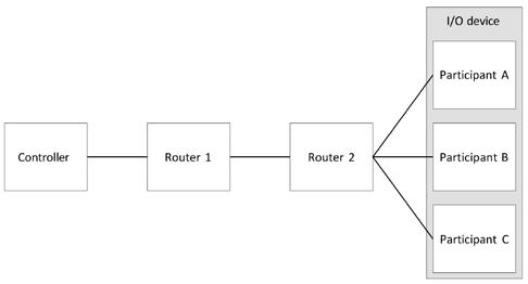
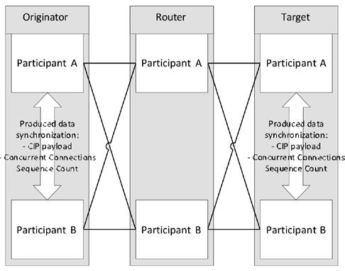
Redundancy solutions come with a price and Concurrent Connections are no exception:
• Within a concurrent connection, the packets with the same CIP payload are sent through all concurrent connection branches. For advanced concurrent connection topologies, this leads to higher use of network bandwidth and higher use of CIP devices’ processing power.
• Concurrent Connections require active synchronization of the redundant endpoints of the concurrent connection. This aspect is not standardized in the CIP specification since it is anticipated that the redundant participants will all be the same device from the same vendor.
Considering the pros and cons listed
above Concurrent Connections are the best communication protocol to be used in a system that requires high availability.
As mentioned above, Concurrent Connections enable any number (Nx) of redundant participants to be used at each router or endpoint (originator or target) along the path of a connection, as shown in Figure 10.
The number of participants used for each router or endpoint is determined by the user to achieve the depth of resiliency their application demands.
To manage all of the (redundant) branches between the connected devices, new "Concurrent" Forward Open and Close services

are introduced in Revision 2 of the Connection Manager object.
The concurrent open and close services differ from the existing open and close services as follows:
1. The existing Port segments are replaced with a Concurrent Connection Path segment that enables the encoding of multiple concurrent connection branches.
2. The Concurrent Connection Path segment for the connection from Figure 11 as configured in the originator participants would contain the following:
3. A Concurrent Connection Protocol Version is introduced to enable future enhancements.
A new Concurrent Connection Packet format (below) is introduced to wrap the existing Real Time formats (e.g. 32-bit header w/ run/idle).
The Concurrent Connection Packet format consists of the Concurrent Connection (CC) Header which contains: Packet Type & Keep Alive field, Packet Length, and Concurrent Connection Sequence Count.
Concurrent Connections are only supported for Transport Class 0 and 1.. Each router participant:
1. Sets up bindings between all of the branches on each side of the participant.
2. Retains the Concurrent Forward Open to automatically resend if a timeout occurs for any of the branches leading to the target.
3. Forwards only the first data packet received for each new data production to all of its branches leading to the next router/endpoint. This applies in both the originator-to-target and target-tooriginator directions.
Additional changes:
1. New revisions of the Link Producer, Link Consumer and Connection objects (enhanced to support arrays of Connection IDs – one for each branch)
2. New Connection Manager CC-specific error codes
3. New Connection Manager diagnostic attributes and connection point
As summarized in the preceding section, the Concurrent Connections solution emerges from existing CIP connections.
Concurrent Connections can be understood as a layer added over existing CIP connections, a layer that enables multiple paths between connection endpoints. Concurrent Connections are managed with a new set of Connection

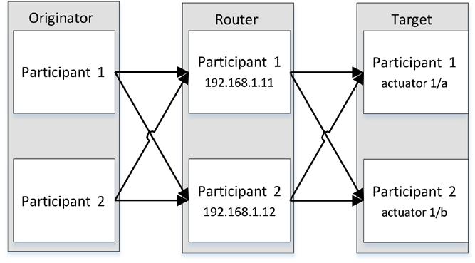
Manager services: Concurrent_Forward_ Open, Large_Concurrent_Forward_Open, and Concurrent_Forward_Close. Those services are derived from the well-known Forward_Open, Large_Forward_Open, and Forward_Close.
The mechanics of transferring CIP data on a single branch of the concurrent connection is exactly the same as the mechanics used to transfer data in a segment of a non-concurrent connection.
Considering the CIP device that already
supports non-concurrent class 0 and 1 connections, the following elements need to be implemented to add a minimum Concurrent Connections capability:
• Concurrent Connection Path Extended Network Segment
• Concurrent_Forward_Open Connection Manager service (the format is the Forward_Open plus one additional field, the Concurrent Connections Protocol Version)
• Concurrent_Forward_Close Connection Manager service (the same format as Forward_Close)
• Counting of concurrent connection branches and connection management decisions based on that count
• Concurrent Connection Header
• Sending packets with Concurrent Connection Header on all open branches
• Receiving packets with Concurrent Connection Header from multiple branches and discarding duplicated packets
• Branch recovery procedure (each participant needs to remember the original Concurrent_Forward_Open and resend it to perform branch recovery) Additionally:
• Originator participants need to synchronize the parameters of concurrent connections they originate.
IPv4 addresses
0xC0A8010B IP address of Router Participant 1
0xC0A8010C IP address of Router Participant 2
Egress port on Router Participants 1 and 2
• Endpoint participants need to synchronize CIP data, Concurrent Connections Sequence Count, and the production time of packets to be produced. The mechanisms of synchronization between redundant participants are vendor specific.
Support for Concurrent Connections will be available in version 4.2 of the Wireshark network protocol analyzer.
“actuator 1/a”
Filip Zembok, Principal Engineer, Embedded Software; Gregory Majcher, Principal Application Engineer, Open Architecture Management; and Darren Klug, Project Engineer, Embedded Software, Rockwell Automation. Visit Website
Time-Sensitive Networking (TSN), since its standardization in 2016, has been moving forward to revolutionize industrial communication by providing deterministic data transmission, precise time synchronization, and traffic prioritization, which are critical for real-time industrial applications.

THE ETHERNET SPECIFICATION FOR TIMESensitive Networking (TSN) is fully developed and was released in 2016 -- and adoption is already underway. TSN provides enhanced Ethernet capabilities with precise timing and synchronization, allowing deterministic data transfer that is essential for real-time industrial applications like robotics, autonomous systems, and factory automation.
But more importantly, TSN enables the co-existence of both time-sensitive communications for demanding applications such as motion control, plus general-purpose TCP/IP communications for safety, data analytics, and IoT communications.
With TSN, various industries have started implementing advanced, reliable, low-latency communication solutions, benefiting from the now-standardized protocols that ensure interoperability across devices and systems. The maturity of the TSN standards, and
supporting products, lets OEM manufacturers build new solutions with standard off-the-self products. The rapid adoption of TSN Ethernet demonstrates its readiness and immediate impact on industrial automation.
Let’s delve into some of the details of features incorporated in Ethernet with TimeSensitive Networking (TSN) and specific technical attributes to that enable real-time data transmission with high reliability and precision.
Key technology benefits
Key attributes and benefits include:
Deterministic Data Transmission: TSN ensures that data packets are delivered predictably within strict timing windows, which is crucial for applications requiring synchronized operations, such as robotics and automated machinery in industrial environments. Determinism is achieved through time
synchronization and traffic scheduling protocols, allowing TSN-enabled devices to manage data flows precisely, even under high network load.
Time Synchronization: TSN uses protocols like IEEE 802.1AS to provide high-precision clock synchronization across networked devices, maintaining microsecond-level timing accuracy. This feature is essential for coordinated, latency-sensitive processes in automation, such as motion control and vision systems, where timing discrepancies can disrupt operations.
Traffic Prioritization and Quality of Service (QoS): Through mechanisms like IEEE 802.1Qbv, TSN assigns priority levels to different data types, ensuring high-priority, time-sensitive data reaches its destination without interruption. This QoS approach allows for a mix of data types—such as control, video, and general information—over a single
network, enhancing operational efficiency and reducing the need for separate infrastructures.
Interoperability: As TSN is built on Ethernet, it seamlessly integrates with existing Ethernet-based networks, allowing for flexible and scalable solutions. This interoperability supports Industry 4.0 goals by connecting diverse devices and systems across manufacturing and industrial environments without requiring specialized cabling or network structures.
These features make TSN Ethernet a versatile, high-performance solution for industries needing precise, real-time control, typically in motion-related applications.
TSN is invaluable for automating complex manufacturing processes that involve real-time, coordinated operations. It ensures low-latency and synchronized communication between sensors, controllers, and actuators, essential in assembly lines and robotic systems where split-second timing impacts quality and efficiency.
The TSN network
Solutions leveraging Ethernet with TSN integrate with existing systems. Most TSN-based applications leverage TSN switches that can isolate the specific TSN data streams within a machine or process that needs it. Consider this as an island of TSN, internal to a machine or process, over a simplified network combining all protocol traffic inside the machine but bridged to the IT and OT network through an Ethernet switch.
There are over a dozen manufacturers of Ethernet Switches that support TSN, from major suppliers such as CISCO, MOXA, Mitsubishi Electric, Phoenix Contact, Belden, among others.
In robotics, TSN's precise timing and low latency ensure seamless operation between robotic arms, sensors, and controllers. TSN supports coordinated multi-axis motion control and complex robotic movements, which are critical in high-speed packaging, welding, and pick-and-place applications.
These applications require the development of TSN-based devices for servo control, real-time I/O, pneumatic or hydraulic valve control and more. Device vendors have been working with their protocol providers to incorporate Ethernet with TSN into their products and many are on the market today. Leading device suppliers are Mitsubishi Electric, Weidmeuller, CKD Corporation, OPTEX FA Co., with many more in development. Device protocol suppliers Hilscher, HMS, Renesas, Sila, Port Industrial and others are delivering support for rapid adoption.
Vendors adopt Ethernet with TSN by implementing TSN-compliant hardware and
software into their industrial communication solutions. Adoption often includes upgrading some network components—such as switches, controllers, and network interface cards— where the TSN benefits are needed. This requires device manufacturers to align with IEEE standards (e.g., IEEE 802.1AS for time synchronization and IEEE 802.1Qbv for traffic scheduling), ensuring interoperability across TSN devices from different vendors. Adopting TSN allows vendors to deliver solutions that meet the high reliability and low-latency requirements of industries that demand real-time data exchange, such as automotive manufacturing and process automation.
The CC-Link Partner Association (CLPA) plays a crucial role in facilitating TSN adoption by setting interoperability standards and providing a collaborative platform for vendors to test and certify their TSN-enabled products.
CLPA's CC-Link IE TSN protocol is one of the first open industrial networks to integrate TSN technology.
It extends Ethernet with TSN’s real-time communication capabilities, supporting seamless data exchange and coordination across production lines. By offering certification for TSN-compatible products, CLPA helps ensure that devices from different vendors can work together reliably, accelerating TSN adoption across industries.
In conclusion, the adoption of Ethernet with TSN, since its standardization in 2016, has revolutionized industrial communication by providing deterministic data transmission, precise time synchronization, and traffic prioritization, which are critical for real-time industrial applications. TSN's ability to coexist with general TCP/IP traffic while maintaining high performance for time-sensitive tasks has made it invaluable in sectors like robotics, automotive manufacturing, and process automation.
The involvement of bodies like the CC-Link Partner Association in setting standards and certifying products ensures interoperability, fostering a unified approach to network upgrades. With ongoing developments and widespread implementation by major manufacturers and device suppliers, TSN is not only enhancing current automation systems but also paving the way for future innovations in industrial networking. This widespread adoption signifies TSN's readiness and its immediate, impactful presence in enhancing industrial automation processes.
Roy Kok, Senior Partner and Alliances Manager, CC Link Partner Association (CLPA).
Visit Website
The process industry is facing the challenging task of increasing the efficiency of its systems, reducing production costs and ensuring the safety of people and the environment. This is leading to innovative approaches when developing new field devices and upgrading existing ones in the process industry.
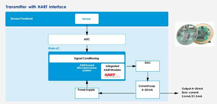
PROCESS INDUSTRIES FACE THE CHALLENGING task of increasing plant efficiency, reducing production costs and ensuring human and environmental safety. As a result, current developments in electronics and measurement technology focus on utilizing digital signal processing, artificial intelligence, real-time data transmission, predictive maintenance functions with easy device replacement, and functional safety.
In this context, digitization or Industry 4.0 plays a crucial role. By leveraging valuable data from the field level, processes and maintenance intervals can be optimized. Web-based software tools enable the diagnosis and parameterization of field devices. Established technologies from factory automation are adopted and tailored to the specific requirements of process automation.
For over 30 years, MESCO has been supporting component manufacturers in process automation with hardware and software development services, as well as expertise in industrial communication, explosion protection and functional safety.
The current requirements for the
development and upgrade of field devices lead to innovative approaches in hardware and software development. The customer requirements are analyzed, summarized, and translated into a concept. This concept includes the consideration of sensor technology, requirements for system design with communication interfaces, a design for compliance with explosion protection as well as functional safety.
A 7-step guide describes the process.
It is crucial to ensure as early as possible that the existing argumentation regarding the suitability and diagnosis of the sensor in terms of functional safety and explosion protection withstands the current standards and requirements of a certifying authority. Therefore, MESCO recommends prioritizing and clarifying this part before starting with transmitter concepts based on the sensor.
After considering the sensors, the
communication properties of the field device play a very important role. The ability to transmit measured values, parameters, and diagnoses in real-time forms the basis for modern Industry 4.0 applications with optimized processes. The system design and communication requirements are specified.
Modern field devices utilize the new standard defined for process automation, Ethernet-APL, an Ethernet-based 2-wire communication interface suitable for both powering the field devices and for use in hazardous areas.
Various software protocol variants can be implemented on this physical interface: Standard Ethernet TCP/IP, HART-IP, PROFINET, OPC UA, and others. The selection of suitable communication stacks is based on the respective development requirements, such as PA-DIM support, functional safety requirements, and market demands.
Once the basic communication interfaces are determined, the field device profile is defined based on it. This involves identifying and logically grouping measured values, diagnoses,
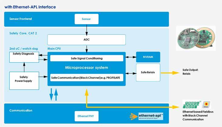
warnings, alarms, internal variables, and parameters. Communication profiles from the Field Device Integration (FDI) specification, as well as HART, PROFINET, and OPC profiles, as well as existing field device parameter sets from device description files (EDDL/GSD), are considered. Additionally, parameters for Industry 4.0 / IoT use cases (PA-DIM) and safety parameters can be added.
After the conceptual phase, detailed hardware and software requirement specifications (HWRS/SWRS) are developed. In this step, system requirements are translated into
concrete hardware and software specifications, and the possible use of MESCO Design Packages is evaluated and analyzed. Communication interfaces, safety requirements and explosion protection requirements are derived. The implementation of measurement algorithms, diagnoses, warnings, alarm handlers, I/O handlers, and communication interfaces is described. After this phase and approval of the concepts, the prototype implementation begins.
The hardware is developed according to the defined specifications, including circuit
SOURCE:
diagrams and printed circuit board layout, with strict adherence to explosion protection and safety requirements. In parallel, the software base system is implemented, and communication stacks as well as the required algorithms are integrated with the field device profiles.
If the device must meet functional safety requirements, this significantly influences the development of field devices. The development process adheres to safety standards (IEC61511, IEC61508). These measures must be consistently followed from conception to certification of the device.
The final step involves the development of an FDI package for the parameterization of the field device. Depending on the host platform, various configuration and parameterization files are created for the field device to ensure compatibility with standard host systems.
This may include the implementation of a GSD file, an Electronic Device Description (EDD), or the creation of an FDI file with a graphical user interface (UI) for FDI-compatible asset management systems. Subsequently, the field device and the corresponding description file are tested for conformity with the fieldbus organization.
Technology report by MESCO. Visit Website
Like many networking techniques, VLANs have made their way to industrial facilities. In this article, we'll examine the many advantages VLANs bring to industrial environments. In this environment, VLANs emerge as a key tool by meeting the dual needs of network administrators for traffic management and security.
SINCE THE LATE 1990S, THE VIRTUAL LOCAL area network, or VLAN, has been a crucial component of modern network strategies. Prior to VLAN development, network engineers were required to create multiple networks and build physically separate LANs whenever an organization needed to partition and isolate multicast network traffic.
VLANs enabled engineers to group end-stations into segments at the data link layer, essentially portioning a single physical LAN into multiple logical or virtual LANs, each with their own broadcast domain. Consequently, broadcast messages could be constrained to a limited number of devices, facilitating granular access control over who can access what within the network.
VLANs are widely used today in mid to large commercial networks to ease traffic congestion, improve network security, and make network configuration, administration and expansion simpler.
Like many networking techniques, VLANs have made their way to industrial facilities. In this article, we'll examine the many advantages VLANs bring to industrial environments.
Simply put, VLANs are isolated, virtual networks within a physical network infrastructure. Each VLAN acts independently as a self-contained network with its own set of rules, security policies, network resources, and broadcast domains. Devices are grouped into a VLAN based on factors such as department, function, or security requirements.
To better illustrate the concept, let's consider the simple example of a small manufacturing company. Assume that the company’s single physical LAN is being segmented into three isolated VLAN networks: one for production, one for sales, and one for accounting. For simplicity’s sake, we are also going to assume that each of these three departments has two network devices that need to be connected to the company’s twelve-port VLAN-enabled managed switch.
VLAN implementation can take various forms depending on operational needs. The most popular kind of VLANs, port-based VLANs, group devices based on their physical connection to a network switch. A more
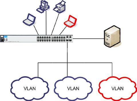
VLANs are isolated, virtual networks within a physical network infrastructure that act independently as a self-contained network with its own set of rules, security policies, network resources, and broadcast domains.
flexible method is provided by MAC address based VLANs, which divide the network according to the MAC address of the device. Though less common, protocol-based VLANs offer network protocol-based segmentation, enabling more precise traffic control.
For this example, we are using port-based VLAN implementation. Here, the network administrator accesses the switch’s management interface to create new VLANs, i.e. VLAN 10 for production, VLAN 20 for sales, and VLAN 30 for accounting, and then assigns two relevant ports of the 12-port switch to one VLAN for each department. The administrator would then plug each device from the three departments into their assigned VLAN port and associate them with their corresponding VLAN ID. To mark messages as VLAN traffic, the switch inserts a VLAN tag into the frame of the IP layer header. Each VLAN has a unique VLAN ID, which is an embedded 12-bit value (from 1 to 4095) in the VLAN tag.
Ports can be either access ports or trunk ports. Host devices are connected through access ports, which are part of a single VLAN,
as is the case in this example. Trunk ports are those that can be assigned to many VLANs. To transport traffic for many VLANs over a single physical connection, network equipment including switches or routers, generally build a VLAN trunk, which is a link or connection that can carry multiple VLANs simultaneously. Known as inter-VLAN routing, this will involve creating sub-interfaces for each VLAN on a router and assigning IP addresses to them.
As a company grows, new segments of the same network can be easily added, or old ones reconfigured without disrupting the entire network or additional hardware investments. VLANs enable a network to scale swiftly and cost-effectively.
In Industrial Control Systems (ICS), it is not uncommon to have hundreds of connected I/O devices, such as RTUs, PLCs, Sensors, HMI, relays, and servers for applications, engineering, front-end and archiving. As the number of devices connected to an ICS increase, the volume of broadcast

messages soars to the point that it starts to consume more of the processing bandwidth of the devices, causing congestion and impeding network performance.
In this environment, VLANs emerge as a key tool in your network arsenal by meeting the dual needs of network administrators for traffic management and security:
• ICS Traffic Management: ICS responsiveness and operational productivity are directly impacted by the efficiency of network traffic management. By segmenting the network, VLANs lessen unnecessary broadcast traffic, which can be especially disruptive in ICS environments. As a result, vital applications run more smoothly on the network and experience less congestion. Real-time control systems depend on the prompt transmission of control commands and real-time data, which is made possible by the ability to prioritize traffic for vital systems via VLANs.
• ICS Cyber Security: By dividing a physical network into many isolated virtual networks, VLANs help to enforce cybersecurity policies, regulate access, and restrict the spread of malicious activities to a limited area by establishing virtual boundaries. An ICS typically has a multitude of different systems and devices, all with varying levels of sensitivity and security requirements. An
administrator can tailor security measures to the differing needs of each segment, improving the overall security posture without compromising the network’s operational efficiency. Additionally, VLANs can be set up to limit access according to user roles and responsibilities, which lowers the possibility of insider threats or unintentional disruption of vital systems.
For all their advantages, VLANs require more configuration and management than the subnetting or routing techniques you may be more familiar with. A complete understanding of the network infrastructure and operating requirements of an ICS is necessary before implementing VLANs on it.
Your first step is a network assessment, which includes identifying critical assets and figuring out the best approach to segment them using VLANs. Identifying network traffic patterns will show which devices need to communicate with each other. To prevent inter-VLAN routing delays, devices requiring real-time communication must be connected to the same VLAN. Remember, because VLANs are not limited by proximity or physical location, devices belonging to the same VLAN can be distributed throughout the ISC physical
network and still function as though they are linked to the same local network switch.
Striking a balance between satisfying every requirement and avoiding complexity could be your toughest task. VLAN configurations that are too complicated may be hard to manage and monitor, which could result in security flaws.
Once in place, it is important to regularly update and examine a VLAN configuration. Changes in the ICS environment, such as the addition of new devices or the repurposing of existing ones, will require adjustments to the VLAN setup.
VLANs are isolated, virtual networks within a physical network infrastructure that act independently as a self-contained network with its own set of rules, security policies, network resources, and broadcast domains.
Antaira managed Ethernet switches are VLAN-enabled to help partition any size network into logical isolated segmentswithout the hassle or cost of deploying new cabling and networking devices, relocating network nodes elsewhere, or rewiring links.
Henry Martel, Field Application Engineer, Antaira Technologies.
Preventing power surges is the leading cause of serial device server failures. Industrial automation systems can be complicated enough as it is without an additional requirement to deploy, maintain, and support yet another device just to provide serial line surge protection.
VOLTAGE SPIKES ARE BRIEF EVENTS THAT rarely last more than a few microseconds. In complex systems, however, even seemingly small events can have serious consequences. This is definitely true of industrial automation systems, in which many different devices need to work seamlessly together in order to maintain normal operations.
Computers and communications equipment are essential components of automation systems, and are particularly susceptible to power surges from voltage and current spikes because they typically have low dielectric strength. In these systems, serial device servers are key communications gateways that connect the broader Ethernet network with specific serial devices. A power surge that damages this vital communications link will bring the entire process to a halt.
A voltage spike is a momentary extreme burst of electricity in an electrical circuit. This energy spike may be short-lived, but could still be strong enough to seriously damage the electronics. Voltage spikes cause corresponding spikes in the current impulse. Two of the most common are spikes from lightning and switching surges:
Lightning: Lightning creates substantial electric discharge at the location it strikes. Lightning that directly strikes a building can clearly endanger its electrical system, but there are other ways for lightning strikes to cause a power surge. For example, when lightning strikes a power transmission line, the effects can cause an equally dangerous voltage spike miles away. Even in locations with infrequent lightning strikes, lightning poses a significant risk and its consequences must be mitigated.
Switching Surge: Many malfunctions in electrical equipment can lead to power surges. Tripped circuit breakers, short circuits, or even power transitions can all create switching surges. These electrical irregularities may be man-made but can cause just as much damage as lightning. A power substation that regularly cycles on and off generates enough switching surges to threaten sensitive electronic devices.
Industrial automation operators generally understand that power surges pose a serious
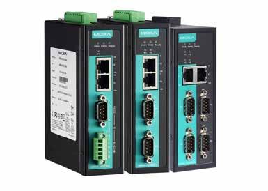
Moxa NPort A Series devices are 1 to 4 port serial to Ethernet device servers for hazardous locations with surge protection for serial, LAN, and power, and 2 KV isolation for serial signals.
threat to their systems and take steps to reduce this threat. Not only do power surges damage and destroy equipment, they cause costly interruptions. In the case of serialto-Ethernet communications, irreplaceable historical data could be lost if the serial or Ethernet ports suffer a power surge. For a serial device server, there are three major points of weakness that could be damaged by a power surge: the serial line, the Ethernet line, and the power line. Many serial device servers offer surge protection on the Ethernet and power lines to protect against this threat. However, most serial device servers leave the serial line unprotected. As a consequence, the serial line is often the vulnerable chink in a serial device server’s surge protection armor.
Substation automation facilities are at particular risk for power surges because they are highly susceptible to both major sources of voltage spikes. As outdoor facilities, substatio ns are more exposed to lightning strikes. As electric facilities that perform electric transformation and switching, switching surges are also a danger. At the same time, electric substations need reliable serial communications in order to perform essential tasks such as reading power meters. If surge damage occurs on a serial line, then any meter data on the associated line will be lost. This combination of increased risk
profile and greater consequences means that robust products with industry-certified surge protection are a must for electric substations.
Full spectrum surge protection
Surge protection is not an option for vulnerable communications links. Effective and comprehensive surge protection reduces downtime and increases system stability by eliminating the most common cause of failure. IEC 61000-4-5 testing is imperative to verify that a device has sufficient surge protection to withstand voltage spikes. IEC 61000-4-5 Level 1 testing is intended for a device that operates in partly protected electrical environments, while IEC 61000-4-5 Level 2 and higher testing certifies that a device can operate in highly electrical environments.
Many manufacturers offer serial device servers with IEC 61000-4-5 rated surge protection on the power and Ethernet lines. However, the same level of integrated surge protection is rare for the serial line. In order to acquire serial line surge protection, device servers are often deployed with additional external surge protection devices. However, this retrofit adds complexity, increases space requirements, imposes additional maintenance costs, and complicates support cases. for harsh industrial environments.
Technology report by Moxa.
Visit Website
In a significant advancement for the industrial automation sector, Siboni and CoreTigo are proud to announce their continued cooperation, utilizing CoreTigo’s IO-Link Wireless technology within Siboni’s servo motors.
Based on the IO-Link IEC 61131-9 standard, it is designed specifically for factory automation applications.
BY INTEGRATING CORETIGO’S IO-LINK WIRELESS technology, Siboni created the PL4 series of wireless, planetary gearbox, electronic drive brushless motors. These low-voltage, compact solution motors, are highly energy efficient while offering superior control precision, making them perfect for accurate industrial applications.
Wireless inside
The integration of CoreTigo’s TigoAir 2 embedded system-on-module into Siboni’s servo motors is a leap forward in intelligent motion control solutions. This enables the mission-critical information required by industrial professionals to maintain optimized production lines.
Siboni’s IO-Link Wireless enhanced motors are suitable for various application fields, such as packaging machines, rotary tables, industrial robotics, logistics, mobile applications (including AGVs and LGVs), and smart transport tracks.
These enhanced motors feature numerous advantages:
Real-time Wireless Control: Cable-free control of the servo motor which increases flexibility and reduces the complexity of deployment and maintenance. With a 5msec latency, it offers the performance of a wired industrial-grade connection, without the wires.
Advanced Sensing Capabilities: As rapidly and continuously rotating motors are subject to various effects, it’s crucial to keep track of their performance, monitoring numerous variables, while machining. Using IO-Link Wireless allows this in an integrated and seamless manner, without having to put the production line to halt for analysis. This includes the ability to sense, transmit, and analyze information from a variety of sensors, including temperature, vibrations, and humidity, for optimization and predictive maintenance.
Wireless Connectivity to Any Automation System: Harnessing IO-Link Wireless for Siboni’s PL4 servomotor series eliminates the need for complex wiring. Additionally, it allows seamless integration with various industrial communication protocols, such as PROFINET, EtherNet/IP, EtherCAT, and OPC UA.
Efficient Data Management: Pre-processing algorithms are implemented
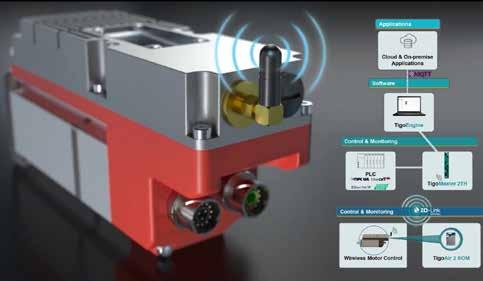
Combined with IO-Link Wireless, Siboni servo motors now demonstrate a new level of capability, without sacrificing reliability and efficiency. Products can be machined in constant motion for a variety of applications, increasing flexibility and reducing maintenance and complexity.
within the motor, limiting data payload and transmitting only essential data to the PLC. This prevents the PLC from traffic overload while allowing the full range of data to flow from the IO-Link Wireless Master to cloud and enterprise applications aggregating all the information.
Comprehensive Analytics: Standard statistical algorithms such as RMS, Variance, Kurtosis, and FFT can be implemented easily, enabling advanced analytics and intelligent insights.
The PL4 series was created by integrating an IO-Link Wireless system-on-module directly into the servomotor, at the field level, enabling it to communicate directly with the IO-Link Wireless Master. At the control level, the IO-Link Wireless Master communicates both with the PLC (with various Industrial Ethernet protocol options) as well as with enterprise applications, via the TigoEngine software application.
In this manner, full control & visibility are enabled from the top of the organization, all the way to the factory floor level. Other benefits of the IO-Link integration include:
• Seamless and complexity-free installation
• Increased flexibility and installation options
• Reducing maintenance, as a result of fewer cables
• Simple future add-on of multiple IOs
Siboni and CoreTigo recently showcased these capabilities at the SPS Italia 2024 expo, showcasing how their collaboration addresses the growing demand for flexible, efficient, and reliable automation solutions. While CoreTigo and other partners demonstrated numerous advanced applications enabled by IO-Link Wireless, Siboni highlighted the practical applications of servomotors in complex industrial environments, emphasizing their role in driving Industry 4.0 initiatives.
IO-Link Wireless is a deterministic, low latency (5 msec) and low synchronization rates (10’s of micro seconds), highly-reliable and scalable universal wireless communication protocol. Based on the IO-Link IEC 61131-9 standard, it is designed specifically for factory automation, coexisting with other networks - both wired and wireless.
Technology report by Core-Tigo (coretigo.com) and Siboni (sibonigearmotors.com).
Watch Video
Data science is still a young field, but it is being incorporated into systems more each day. The goal is to maximize value by enabling data scientists as many capabilities as possible, and not frustrating them with limited capabilities.
DATA SCIENCE USES STATISTICS AND algorithms to extract or extrapolate knowledge and insights from noisy, structured, and unstructured data. Data scientists often don’t know what they are looking for until they see patterns or associations. For this reason, all data can be valuable in analyzing and optimizing a process or system.
Many CIP-enabled devices possess a rich collection of data that never gets used in a user’s control program. Furthermore, some of that data is buried in the device and not readily exposed. The CIP specifications provide some mechanisms to make that data discoverable, but more could be defined.
This article explores options using currently specified techniques as well as some new proposals for making device data more discoverable and understandable thereby enabling its use in data scientist use cases.
Introduction
Data scientists use data to answer questions, make predictions, and solve problems. They collect, clean, organize, and analyze data before drawing their conclusions. But what data are they looking for? It depends.
First, the data scientist must understand the problem space. Some industrial possibilities are:
• Identify areas for energy savings.
• Predict when a component will fail.
• Increase the efficiency of a process.
• Identify deteriorating quality in a process or a product being produced.
• Diagnose performance or quality differences between similar production lines or facilities.
In some of these cases it would be easy to identify the data needed. In others, the selection of data is less clear. Let’s look at a few use cases from above.
User Story: As a plant manager, I want to identify opportunities for energy savings. The data scientist could start by collecting the power consumption of all products in a plant and ranking them by their power usage. Studying when and how the highest consumers are used could yield energy saving ideas. In this case identifying the needed data is straightforward, but it does rely on knowing where that data is located and how to retrieve it.

User Story: As a plant manager, I want to predict when equipment will fail so that I can proactively schedule maintenance downtime to replace it.
Data scientists can collect data directly related to a component’s usage such as hours of operation or a cycle count related to movement. If devices provide predicted lifetimes, they can be used to compare against the actual usage. However, predicted lifetime data might be based on idealized environmental conditions. The actual environment may be accelerating wear. Data that reflects the surrounding temperature or humidity might be of interest. The turbidity or viscosity of any fluids involved may be important. Discovering these data items will require some investigation and knowledge of the application. Additionally, this use case may also require taking baseline measurements (e.g., vibration monitoring measurements or power consumption) and then tracking changes over time.
User Story: As a regional production manager, I want to understand performance and quality differences between two similar plants.
Depending on how well the production
facilities and processes are understood, it may or may not be clear what data to use in this case. The data scientist may need to collect a large sample of many different sources of data and simply look for differences. The differences between the data from the facilities may point to areas for further investigation. The plants being compared in this example could be using equipment from different vendors or even different network technologies. To compare the data correctly, the data scientist would need to know that the data collected from the differing equipment was equivalent.
User Story: As a plant manager, I want to detect deteriorating production quality and identify the cause early so that remediation can occur with minimal product loss.
To diagnose decreasing quality, data scientists may need to collect a lot of random, unrelated data over a period of time and look for associations and trends in the historical data. Because the associations are unknown, the data scientist may be looking for any kind of data available. The ability to browse devices in order to see all the data they have available would be very helpful in this case.
The examples above are intended to
Table 1 - Message Router's Object List Attribute.
highlight problem scope ranging from welldefined to highly unstructured. In each case, the data needed, and the steps taken to collect it might be different. Industrial automation products have data that is intended to be exchanged in real time connections with a PLC or DCS. Many products also have additional data available that never gets used in a control program.
Things like diagnostics, statistical counters, event logs, and status variables are collected by field devices and are waiting to be used. It is likely that some of this data will be of high value to a data scientist. To better enable data scientists, data needs to be discovered, understood, and delivered in an efficient manner.
Products should efficiently expose the data they possess. Exposed data should be presented along with meaningful metadata, so the meaning of the data is understood. Finally, data should be made available using transport mechanisms that are efficient for the type, amount, or frequency of data. The CIP specifications already define some techniques to present, define, and transport data. The rest of this article will document some of those along with proposals for how we can do better.
Devices can easily be found on an ethernet network. The EtherNet/IP Adaptation of CIP (Volume 2 of the CIP Networks Library) recently mandated support for the Link Layer Discovery Protocol (LLDP) in all products. Devices supporting LLDP advertise information to stations attached to the same LAN for the purpose of populating a physical topology. Identifying information (i.e., a device’s CIP identity) is returned in responses.
Volume 2 also defines the ListIdentity command sent using an Encapsulation packet over TCP or UDP. Responses to this message include data from all the required attributes of the Identity object as well as the current state of the device. Clients can send this message as a broadcast and quickly discover all EtherNet/ IP devices on a network.
The combination of these two mechanisms
Object_list STRUCT of A list of supported objects
Number UINT
Classes ARRAY of UINT
Number of supported classes in the classes array
List of supported class codes
provides for an effective way to construct a topology tree and identify all the EtherNet/ IP devices. The discovery process could be improved if clients were able to discover important capabilities or features that were supported by devices. Volume 8 contains one example of this. Devices that support CIP Security are required to include their supported CIP Security Profiles in response to the ListIdentity request. This same mechanism could be used to indicate support for other important capabilities.
To request data from a CIP-based product, you must construct a path to that data. Paths are addressed to objects. They can be directed to the object class, or to a specific instance of the object. Attributes of the class or individual instances represent the data.
If nothing was known about a product, you may be tempted to use a brute force technique for discovery, sending many requests to discover what a product had to offer. The first step would be to send a request to every possible class code (65,535 possible) to see which classes were supported. For any objects that responded, you would then need to discover the instances (4,294,967,295 possible) of that object that existed. Finally, for each instance you could send a request to every possible attribute id (65,535 possible). As you can see, this technique would result in trillions of requests and take too long to be useful.
The good news is that several techniques already exist to limit the number of messages needed to perform this type of discovery. The bad news is that most products do not support this functionality because it has always been optional.
The Message Router Object has an instance attribute (Attribute 1) that enumerates all the supported objects in an implementation. If this attribute is supported, a client can avoid the brute force method of discovering the supported objects.
This attribute provides a very efficient response indicating all the objects contained in a device. The next step would be to discover
Structure with an array of object class codes supported by the device
The number of class codes in the classes array
The class codes supported by the device
the instances of each object class.
Volume 1, Chapter 4 of the CIP Networks Library documents the CIP Object Model. As part of that model some Class Attributes are defined as common to all CIP objects. Attributes 2 and 3 help you to discover which instances are currently created in an object. Attributes 200 and 201 are used if a device supports instances greater than 65,535.
These attributes would be all you needed if the value of Max Instance equaled the Number of Instances. However, if the two do not match, you must try all the instances between 1 and Max Instance to discover the instances that the device currently has instantiated. There are no rules about which instances can be created. In a worst-case scenario, a device may have created instances from the top of the range and worked down or has some dynamic instantiation method that results in a sparsely populated list.
A better solution might be to provide an attribute similar to the Message Router’s Object_List that would return an array of the instances that currently exist.
This attribute would be efficient for most devices. For implementations where the presence of many instances would not allow the response to fit in one packet, CIP provides the Find_Next_Object_Instance service. This service is directed to a class specifying an instance to start with and a maximum number of return values. The class will return a list of existing instances starting with the next
Maximum instance number of an object currently created in this class level of the device.
Number of object instances currently created at this class level of the device.
Maximum instance number of an object currently created in this
Number of object instances currently created at this class level of the device.
The largest instance number of a created object at this class hierarchy level.
The number of object instances at this class hierarchy level.
The largest instance number of a created object at this class hierarchy level.
The number of object instances at this class hierarchy level.
Table 2 - Reserved Class Attributes 2, 3, 200, and 201. Footnote2: Attributes are optional. If the device chooses to implement either Max Instance or Number of Instances attribute, it shall implement the UDINT version if it supports instances greater than 65.535, else it shall implement the UINT version.
Table 3 - Proposed Instance List Attribute.
Number UINT
Instance Data Type UINT
Instances ARRAY of Instance Data Type
Number of instances in the Instances array
Structure with an array of currently created instances of this object class
The number of instances in the Instances array
Number of instances in the Instances array 0 = USINT 1 = UINT 2 = UDINT
List of supported class codes
The instances that currently exist in this object class
Number of attributes UINT
List of optional instance attributes utilized in an object class implementation.
Number of attributes in the optional attribute list.
The largest instance number of a created object at this class hierarchy level.
The number of attribute numbers in the list. Optional attribute list ARRAY OF UINT List of optional attribute numbers.
Maximum ID Number Class Attributes UINT
The attribute ID number of the last class attribute of the class definition implemented in the device. 7 Optional Get
Maximum ID Number Instance Attributes UINT
The attribute ID number of the last instance attribute of the class definition implemented in the device.
The optional attribute numbers.
Table 4 - Reserved Class Attributes 4, 6, and 7

instance greater than what was passed in. Returning 0 indicates that the end of the list of created instances has been found. The example in Figure 1 shows a collection of sparsely created instances returned in only two exchanges.
This service works very well if the implementation does not support instances
greater than 65,535. The Find_Next_Object_ Instance service was defined before CIP was extended beyond UINT instances. To find UDINT instances, the client would need to use the existing attributes along with the brute force method. Alternatively, the service could be redefined (or a new service could be developed) that supported UDINT instance numbers.
Once the objects and their instances are discovered, finding the supported attributes can be performed. The CIP Object Model currently has the following Class attributes defined to help with this process. If the client has knowledge of the Class definition, attribute 4 can be helpful. If the Class definition is vendor specific, or the
The largest instance number of a created object at this class hierarchy level.
The number of attribute numbers in the list.
5 - Proposed Attribute List Attributes
The number of attributes in
[Discrete Input Class]
Revision = 2;
MaxInst = 8;
$ Revision 2 of the object is implemented
$ The highest instance number that exists in the product is 8 Number_Of_Static_Instances = 8; $ There are 8 static instances present Number_Of_Dynamic_Instances = 0; $ There are no dynamic instances
Class_Attributes = 1; $ Class attribute 1 is supported
Instance_Attributes = 3, 4, 5, 6; $ Instance attributes 3, 4, 5, and 6 are supported
Class_Services = 0x14; $ Get_Attribute_Single is supported for class attributes
Instance_Services = 0x14, 0x10; $ Get_ and Set_Attribute_Single are supported for instance attributes
Object_Name = “Discrete Input Point Object”
Object_Class_Code = 0x08;
client is not CIP-aware, attribute 4 is of no value. Attributes 6 and 7 are of some use, however just like with the Max Instance attribute, the value is diminished when large numbers of attributes exist. Therefore, new class attributes that simply return a list of all supported attributes make the most sense.
For implementations where many attributes are supported and the response would not fit in one packet, the existing attributes (4, 6, and 7) could be used along with the brute force method, or a new service could be developed. We could specify a Find_Next_Object_Attribute service patterned after the Find_Next_Object_ Instance service.
There are always arguments against introducing more required functionality which would negatively impact constrained devices, or because some devices are already very complicated. To respond to these objections, much of the discovery information could be exposed using offline device description files (e.g., EDS).
The Public Object Class and Vendor Specific Object Class sections of the EDS define a way to expose a product’s supported objects, instances, and attributes. An example is shown below for the Discrete Input Point object.
As you can see, it would be possible to fully describe the objects in a device’s implementation using these EDS keywords. Provisions were also made to describe vendor specific objects in the same way. The only thing that would need to be discovered online would be any dynamically created instances of an object.This is an example of a powerful EDS feature that can be used to enable the discoverability and understandability of device data.
CIP’s information model (metadata) is documented in its object definitions. For
publicly defined objects an ODVA member can know the details of any object from the CIP specifications. However, vendors are free to extend publicly defined objects or even create their own. Those vendor specific additions would not generally be known to other vendors. And non-member actors, specifically end users, have no access to the CIP specifications. This can make it challenging for a data scientist to have the context of the available data.
Currently there is no online mechanism to communicate a CIP object’s metadata. The Parameter Object comes close, but it was written for configuration parameters. The object allows for “Stub” or “Full” definition of parameters. Stub parameters fall short of what is needed for the data scientist, and full parameters might be too heavyweight for many products. A simple and efficient mechanism could be introduced to access object metadata by extending our use of logical segments for paths.
CIP uses encoded items, called segments, to reference or describe elements within a device’s information model. Those segments can be used to specify a path indicating relationships among different objects. For our purposes we will be talking about paths of logical segments. These are commonly used to reference an object, its instances, or an instance’s attributes. A new logical segment could be defined to provide object metadata.
The CIP object model presents class and instance attribute data using tables as shown below. Each of the eight columns specifies some property of the attribute. You could say an attribute of the attribute, but that might get clumsy. These eight columns are essentially the metadata properties for the attributes.
Columns 2-7 could be standardized metadata properties for all attributes. In other words, the name of any attribute could be addressed by referring to property 5 of that attribute or the data type as property 6.
A new Extended Logical segment (0x3C) could be defined to represent these new metadata properties. See the CIP Networks Library Volume 1, Appendix C, Section C-1.4.2 for a complete definition of Logical segment types.
If a Get_Attribute_Single request was sent with this path, the response should be a string equal to “Product Code” which is the value of the Name property of the Identity Object’s third attribute.
More work would need to be done on this idea. The items in columns 2-5, and column 7 are straightforward and could be exposed with minimal specification work. Column 6, Data Type, would require some investigation for things like structures and arrays. There are constructs defined in Volume 1, Appendix C that may be used. Standardizing the information in column 8, Semantics of Values, would require significant changes from how it is currently used but is possible using some form of constraint language. If we only accomplished Columns 2-5 and 7, that would provide meaningful metadata to someone without access to the object definition. Exposing column 6 is particularly important and within our reach. Column 8 would be powerful and complete the model for online metadata access.
Param, Assem, and Variant entries in an EDS file can be used to describe any data. Param entries provide a very comprehensive set of fields to fully describe data including fields like Parameter Name, Data Type, Units String, Help String, etc. The example below exposes details about the Connection Manager Object’s Percent I More complex data such as structures can be represented in Assem entries. Vendors could describe any, or every supported attribute in their products’ EDS files. With this information any client could
Table 6 - Attribute Properties.
[Params]
Segment Contents Notes
Segment Type = Logical Segment.
[20][01][24][01][30][03][3C 07][05]
Param1 = 0, 6,"20 06 24 01 30 F0",
0x0002,
Param1 = 0, 6,"20 06 24 01 30 F0",
0x0002,
0xC7, 2,
"Percent I/O Utilization",
20 01 indicates class 1 (Identity Object) 24 01 indicates instance 1
30 03 indicates attribute 3 (Product Code)
3C 07 05 indicates metadata property 5 (Name)
$ Link Path Size, Link Path to Connection Manager Object
$ Descriptor [Params]
$ Link Path Size, Link Path to Connection Manager Object
$ Descriptor
$ UINT Data Type, Data Size
$ Name "%",
$ Units
"Indicates what percentage of the I/O communications resources are in use in this device in units of 0.1%",
0,1000,0,
0xC7, 2,
"Percent I/O Utilization",
$ Help string
$ Min/Max/Default
$ Unused fields
$ UINT Data Type, Data Size
$ Name "%",
$ Units
"Indicates what percentage of the I/O communications resources are in use in this device in units of 0.1%",
0,1000,0,
$ Help string
$ Min/Max/Default
$ Unused fields
present a very complete picture of the data to a human actor.
Finally, getting all this data takes time, especially when it needs to travel from the edge to the cloud. Providing efficient means to retrieve this information will make its collection more practical and have less impact on the high priority traffic in the system. Highly granular, grouped, and bulk transfer mechanisms should be available to cover any amount of data and the variety of data science use cases.
Request, response messaging whether unconnected or over a Class 3 connection provides a highly granular approach to getting the data. These exchanges are best suited for small amounts of specific data but could be expensive in terms of network bandwidth when many requests are made.
For multiple small requests, the Message Router Object provides the Multiple_Service_ Packet service. Using this service allows you to specify an array of CIP service requests in one packet. This is a more efficient mechanism than sending a single request and then blocking while waiting for a response. However, this service is still subject to
packet size limitations. For much larger requests, the Message Router Object provides the Send_Receive_Fragment service. This service is used when the request, response, or both exceed the size of a single packet.
We have good options for granular and grouped data collection, but new transports should be defined that would facilitate the exchange of large amounts of data. Volume 1 reserved Transport Class 4 as Non-blocking, Class 5 as Non-blocking, fragmenting, and Class 6 as Multicast, fragmenting all without definition.
Now would be an appropriate time to revisit these and define an effective bulk transport. This would not only benefit the Data Scientist but may also support faster firmware update or device configuration times.
CIP provides a rich collection of optional functionalities. This article serves several intended purposes: first to shine some light on these lesser-known functionalities, second to spark a conversation and participation in improving what we already have, and third to build support in the ODVA vendor community for incorporation of these features into products.
Our end users will benefit from:
• Online discovery aids like the Message Router’s Object_List attribute and every object’s class attributes (Max Instance, Number of Instances, Optional attribute list, etc.).
• Online metadata (once defined)
• Offline descriptions of all valuable data within a product (i.e., rich EDS files with Object Class sections and Param entries to define attributes)
• Support for alternative transport mechanisms like the Multiple_Service_ Packet and Send_Recieve_Fragment services.
Data science is still a young field, but it is being incorporated into our systems more each day. As our end users discover the data that we have been providing, they will come to value our products even more. We want to ensure that we maximize that value by enabling data scientists as much as possible and not frustrating them with limited capabilities.
Greg Majcher, Principal Application Engineer, Rockwell Automation.
The challenges industrial environments face when processing AI data at the edge can include cost and power constraints, as well as limited memory resources. While cloud solutions can accommodate higher costs and power requirements, edge applications often operate within stricter financial and energy limits.

As Artificial Intelligence (AI) technology shifts from centralized cloud systems to ‘the edge,’ industrial applications face major hurdles in processing AI data. A key challenge is balancing AI performance with power efficiency, particularly for demanding tasks like Generative AI, where high performance demands often clash with energy constraints. Real-time processing is crucial for industries needing timely data-driven decisions, but doing so with limited resources remains a significant obstacle.
For instance, applications such as autonomous vehicles (drones, cars, industrial robots), where instantaneous decision-making is essential–any delay in data processing
could have dire consequences. Additionally, integrating new AI technologies with existing architectures and legacy systems often poses significant technical, cost, and institutional hurdles. Expanding AI applications to edge environments can also increase exposure to cyber threats.
When AI processing relies on continuous cloud communication due to limited edge capabilities, it increases the risk of exposing critical data, highlighting the importance of robust security measures. AI platforms capable of in-system processing without relying on cloud communication are therefore more desirable, offering lower latency and higher levels of safety and security.
Finally, challenges with AI applications at the edge can include cost and power constraints, as well as limited memory resources. While cloud solutions can accommodate higher costs and power requirements, edge applications often operate within stricter financial and energy limits, making lower-cost, energyefficient AI processing crucial.
Furthermore, the memory capacity at the edge is limited compared to cloud systems, necessitating efficient use of available memory to maintain high performance. Physical space constraints further complicate matters, as edge devices must fit within compact environments such as drones, 5G base stations, manufacturing robots, or aerospace solutions.
Overcoming these challenges
EdgeCortix addresses these challenges with innovative solutions. The company’s SAKURA-II AI accelerator platform is designed to deliver near cloud-level AI performance while drastically improving energy efficiency, making it exceptionally suitable for demanding edge workloads. Additionally, the Dynamic Neural Accelerator® (DNA) architecture provides runtime reconfiguration, optimizing data paths for efficiency while providing real-time processing capabilities, which ensures low latency—a key requirement for edge applications.
The MERA Compiler Framework facilitates the deployment of AI models in a frameworkagnostic manner, supporting seamless integration with existing systems and diverse processor architectures. EdgeCortix also offers modular AI accelerator solutions, such as PCIe Cards and M.2 Modules, which seamlessly integrate into existing systems to streamline AI deployment timelines.
Real-world applications
Real-world deployment examples illustrate the effectiveness of these solutions. In smart cities, EdgeCortix technology can enhance AI capabilities for traffic management and security monitoring by processing large volumes of data from cameras and sensors in real-time. Additionally, edge AI solutions can improve public safety by enabling highresolution video analysis in crowded areas and enhance emergency response with accurate recognition of people and objects.
In manufacturing, edge AI solutions can optimize production lines, predict equipment failures, and improve quality control through immediate sensor data analysis, improving overall efficiency and reducing downtime. In the aerospace industry, these solutions can monitor aircraft engine performance and predict component wear, contributing to safety and reliability while lowering maintenance costs.

AI has many applications in sorting through volumes of big data coming from manufacturing floors today. At the edge, higher speed, higher resolution sensors including video reveal more about processes and product quality than ever.
Overall, as AI continues to proliferate across various industries, the challenges faced by embedded designers transitioning from cloud to edge solutions become increasingly necessary and significantly more complex. Selecting the correct AI hardware solutions platform and provider is crucial in order to overcome these obstacles and successfully implement edge AI products. By evaluating AI accelerators, like EdgeCortix's SAKURA-II, against the key design challenges outlined, engineers can develop energy-efficient and high-performing solutions that meet the demands of modern applications within existing systems.
This shift toward edge AI not only enhances real-time data processing capabilities but also supports the growing need for costeffective and scalable AI technologies across sectors such as smart cities, manufacturing,
telecommunications, aerospace, and others. With the increased demand for Generative AI processing at the edge, it is critical for AI solutions to operate these complex, multibillion parameter models efficiently with very low power consumption.
SAKURA-II meets these generative AI requirements using DNA architecture, optimizing data paths, and employing parallelized processing for maximum efficiency. These advancements demonstrate EdgeCortix's ability to tackle the critical challenges of AI data processing at the edge across various business sectors. They also illustrate how EdgeCortix solutions are engineered to provide superior performance and power efficiency for edge AI applications.
Jeffrey H. Grosman, Executive VP of Marketing & US Operations, EdgeCortix.
Visit Website
Linux®-based real-time control available as a virtual PLC along with new multi-I/O interface in one device.
WORKING ON THE BASIS OF TWINCAT FOR LINUX®, Beckhoff is opening up more application possibilities that enable resource-efficient, virtualized distribution of TwinCAT applications. Both the TwinCAT PLC runtime and TwinCAT functions in the form of containers can be operated not only locally on the controller, but also in a data center. Communication with decentralized I/Os can take place via the EK1000 EtherCAT Coupler in this case.
Not only does TwinCAT for Linux® allow the TwinCAT automation software to be executed on the basis of the Linux® operating system, but it also enables TwinCAT to be distributed and operated in the form of containers. Thanks to the modular structure of TwinCAT, the individual TwinCAT applications can also be distributed across several containers.
ADS-over-MQTT technology, which has been established on the market for many years and is familiar to users, is available for cross-network communication and can also be used for integrating a virtualized engineering system.
This implementation of a virtual PLC means that the application options can be extended to the local data center as well, allowing certain control or simulation and test tasks to be outsourced from the machine or its control PC. This operating mode holds particular appeal for applications with lower real-time requirements. Communication with the decentralized I/Os can take place via the EK1000 EtherCAT Coupler, which supports the integration of the I/Os via a switched and routed IP network. This simplifies the

distribution of various TwinCAT applications and enables the central integration of I/Os located at different points in the company via the IT system.
The advantages of virtual control technology with TwinCAT and Beckhoff hardware:
• Increased flexibility: virtual control systems can be easily scaled and adapted to different requirements
• Lower costs: there is less need for physical hardware in the field, reducing the associated costs
• Simplified maintenance: maintenance and software upgrades are easier to carry out as no physical hardware is affected
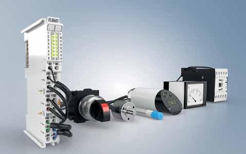
SOURCE: BECKHOFF
The EL8601-8411 EtherCAT Terminal supports up to 12 signal interfaces and nine signal types in one multi-purpose I/O module.
Beckhoff’s new EL8601-8411 EtherCAT Terminal offers incredible interface flexibility in a compact, 12-mm-wide design. With up to 12 signal interfaces (8 x DI, 2 x DO, 1 x AI, 1 x AO) and nine signal types in one terminal, the multi-interface is ideal for numerous applications. These use cases include systems that require only a few complex signals or to enable highly flexible signal configuration on custom machines without adding singlepurpose hardware.
The EL8601-8411 offers a large number of configurable combinations to create a compact solution for applications where only a few complex signals are required. For example, it can serve as an ideal complement to microcontrollers, such as the CX7000 Embedded PC, which offer a direct backplane connection to the Beckhoff I/O system.
In addition to the digital inputs and outputs, one analog input and one analog output can be configured as a current or voltage signal. The digital inputs with configurable filter times can also be used for 24 V HTL encoders with A/B track, including latch and gate function, or as an up/down counter with a counting frequency of up to 100 kHz. Two of the digital outputs can be used as a PWM signal that can be modulated in both pulse width and frequency in a range of 20 Hz to 25 kHz.
Beckhoff
Learn More
New products include advanced IIoT controllers, servo drives, and HMI solutions.
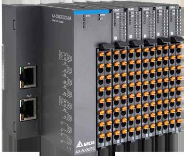
DELTA, A GLOBAL LEADER IN POWER management and a provider of IoT-based smart green solutions, unveiled its latest advancements in industrial automation at SPS Nuremberg 2024.
The portfolio includes solutions engineered to meet the stringent standards and unique requirements of the European market, including the new AC Servo Drive A3-EP Series, the Advanced IIoT Controller AX-5, and the Human Machine Interface DOP-300S Series. Recognizing the critical importance of cybersecurity in IIoT, Delta has achieved certifications in IEC 62443, ISO/IEC 27001, and ISO/IEC 27701 to ensure the security of our products, services, and comprehensive solutions.
Michael Mayer-Rosa, Senior Director, Industrial Automation Business Group at Delta Electronics EMEA Region, said, "With the addition of our D-Bot series collaborative robots (cobots) earlier this year, we’re further enhancing our complete solutions portfolio to meet the evolving needs of the European market.
Each innovation highlights Delta’s commitment to precision, advanced safety protocols, and seamless connectivity in the evolving landscape of automation. Moreover, we are placing an increased focus on functional safety, which is essential, especially in the mechanical engineering industry, one of our key target sectors."
Delta’s Advanced IIoT Controller AX-5 Series is designed for the precision machinery
industry and high-speed, high-precision machining. Equipped with a powerful Arm Cortex 4-core processor, the AX-5 Series supports multitasking and controls up to 64 axes.
This enables seamless synchronization with servo drives, AC motor drives, and remote I/O modules. It supports multiple industrial communication protocols and offers a highly integrated single software development platform. This innovative design helps equipment manufacturers reduce hardware expenses, service costs, and development time.
The AC Servo Drive A3-EP Series has been developed specifically for Europe’s dynamic automated manufacturing sector. Building on Delta’s high-end A3 Series, the A3-EP Series offers precise control, high speed, and energy efficiency. It integrates seamlessly into Delta’s DIAStudio ecosystem, offering a user-friendly interface and auto-tuning capabilities for optimized system configuration.
Equipped with TÜV-certified functional safety features, including Safety over EtherCAT (FSoE), the A3-EP Series ensures safe and reliable operation in critical applications. As an open platform, the A3-EP Series supports EtherCAT and advanced communication protocols (FoE, EoE) and is compatible with both Delta and third-party motors, making it adaptable across a wide range of European applications.
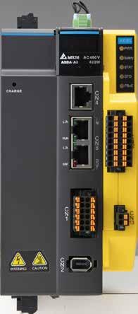
HMI DOP-300S Series: smart connectivity for Industry 4.0 and IIoT
Delta’s new HMI DOP-300S Series is designed for advanced control and monitoring in smart production and Industry 4.0 environments. Available in 7” and 10” screen sizes with optional Wi-Fi and 4G LTE connectivity, the DOP-300S Series provides OEMs and system integrators with the secure connectivity needed for IIoT applications. Equipped with dual Ethernet ports and a dual-core ARM processor, the DOP-300S Series facilitates smooth operation and enables remote monitoring and troubleshooting from anywhere, reducing downtime and enhancing operational efficiency. The DOP-300S Series also has built-in SCADA features, enabling data visualization and remote monitoring. This HMI solution supports multiple PLC and communication protocols, with cloud-based visualization and data storage capabilities, providing a scalable, future-proof interface for European manufacturers.
Delta Learn More
Freelance distributed control system boosts plant efficiency and helps future-proof operations.
THE LATEST VERSION OF THE ABB FREELANCE distributed control system enhances plant connectivity, ensuring fast and reliable communication for optimal real-time data processing and control.
Freelance 2024 enables secure and up-to-date operating environment with Windows 11 compatibility and MS Defender integration. A PROFINET and NAMUR Open Architecture ensures efficient data exchange and integration across various systems, facilitating technology adoption and operational scaling.
Leveraging 30 years of continuous innovation and reliability, ABB’s updated Freelance 2024 distributed control system (DCS) offers greater plant adaptability, faster and more reliable device communication, improved system security, and seamless data exchange. The updated version ensures future-proof upgrades for existing projects and easy implementation in new projects.
“Today more than ever process industry plants need to be able to adapt quickly to stay relevant in a rapidly changing digital landscape with unpredictable market demands and increasing regulations,” said Stefan Basenach, Senior Vice President, Process Automation Technology, ABB. “Freelance 2024 is designed to help plant managers focus on strategic initiatives by simplifying operations and improving system flexibility. It meets current industrial demands and

prepares plants for future technological advancements.”
Freelance 2024 facilitates enhanced connectivity, faster data transfer, more precise control and monitoring of data together with an improved network performance, leveraging the new PROFINET integration and support of Ethernet Advanced Physical Layer (APL).
With its scalability and integration
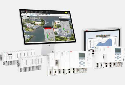
capabilities, Freelance 2024 is designed to help plant operators reduce downtime while simplifying tasks. NAMUR Open Architecture support via OPC UA ensures secure and more standardized data exchange across various systems and devices, increasing interoperability and simplifying the integration of new technologies. Plant agility is further enhanced thanks to Freelance 2024 controllers, which support Module Type Packages (MTP) for ‘plug and play’ Modular Automation.
As plant owners prepare for the nextgeneration workforce, Freelance 2024 helps bridge the skills gap with an intuitive, userfriendly interface that reduces training time and simplifies engineering, operations and maintenance.
ABB’s Process Automation business automates, electrifies and digitalizes industrial operations that address a wide range of essential needs – from supplying energy, water and materials, to producing goods and transporting them to market. With its ~20,000 employees, leading technology and service expertise, ABB Process Automation helps customers in process, hybrid and maritime industries improve performance and safety of operations, enabling a more sustainable and resource-efficient future.
ABB Visit Website
SOURCE: ABB
Comprehensive, subscription-based solution simplifies the deployment and management of IoT investments.
Digi International announced the launch of Digi 360, an all-new subscription-based solution supporting ease-of-use, deployment visibility and optimized ROI for Digi cellular routers.
Delivering a comprehensive connectivity package, Digi 360 includes purpose-built devices, software, services and enhanced warranty to simplify the rollout of IoT projects and ease the challenges faced by enterprises when configuring, deploying and managing their deployments.
With Digi 360, customers benefit from Digi’s robust devices that enable automation and edge computing across a wide range of enterprise, industrial and transportation environments, as well as the latest tools and resources to efficiently manage and secure deployments across evolving use cases. This comprehensive solution delivers an unparalleled customer experience that minimizes friction and maximizes return on investment.
“Digi 360 stands as the definitive solution for secure wireless connectivity deployments,” said Landon Reese, Vice President of Product Management at Digi International. “Bringing together software, management capabilities, state-of-the-art edge devices and expert support into a unified, comprehensive package, Digi 360 ensures our customers experience unmatched efficiency, security and reliability while enjoying significant cost savings.”
An all-encompassing, future-proof solution, Digi 360 integrates the critical components of Digi's offering to enable the best customer experience, while reducing friction and simplifying deployments:
Digi Remote Manager is an intelligent network command center, providing centralized control, management, security, and edge intelligence.
Providing a single, secure platform that allows network health monitoring and instant alerts from across the network, Digi RM has the ability to both diagnose and repair issues, reducing the need to deploy a technician or roll a truck. Additional features include API access, simplified configuration, out-of-band management, scheduled automation and access to a range of value-added services.

Digi 360 offers comprehensive cellular solutions, including purpose-built devices, software and services, to help customers optimize their IoT investments and maximize ROI. These complete solutions are designed to simplify IoT complexity, and ease the challenges enterprises face in configuring, deploying and managing their IoT initiatives. SOURCE:
Renowned for their exceptional performance even in the most challenging conditions, Digi’s easy-to-use, industry-leading devices offer configurability, scalability and purpose-built design. Additionally, Digi edge devices are designed for extended product lifecycles, world-class reliability, mobile and fixed wireless access and integrated software and security, to keep critical systems running efficiently.
Digi Expert Support provides technical assistance, including 24/7/365 expert global support within a four-hour response service level agreement for priority case resolution, configuration and network troubleshooting, return merchandise authorization (RMA) assistance, and feature/functionality inquiries. Professional services are also available for integration with third-party devices, code debugging, and more, along with a Customer Success program for mission-critical deployments.
Digi 360 includes an enhanced Limited Lifetime Warranty, offering edge device protection for active subscribers for the full length of the subscription.
Additionally, customers can enhance their
Digi 360 subscriptions by opting for add-on services, to customize their solutions to their unique deployments. Options such as Digi Containers, Digi WAN Bonding and Digi Mobile VPN provide additional capabilities, optimizing the customer experience and offering a tailored approach to meet the advanced security, uptime and quality of service needs of demanding applications.
“Digi 360 offers so much more than connectivity; it’s a complete, secure solution that eases complexity, alleviating the challenges in configuring, deploying and managing IoT deployments,” Reese said. “Designed to evolve with the alwaysin-flux IoT landscape, Digi 360 provides our customers with a future-proof investment as well as much-needed peace of mind.”
With Digi 360, enterprises and municipalities not only have robust devices that enable automation and edge computing across a wide range of environments, but also the tools and resources to efficiently manage, secure, and scale those deployments while enhancing the value of their networks in evolving use cases.
To learn more about Digi 360, please visit: www.digi.com/Digi360.
Digi
Learn More
Siemens launches intelligent link module for greater data transparency in industrial automation.
WITH THE INTELLIGENT LINK MODULE SIRIUS 3RC7, Siemens now offers a quick and easy way to achieve complete data transparency right down to the field level. The plug-andplay expansion module combines information technology (IT) and operational technology (OT) with minimal installation and commissioning effort.
This means that the data available at the consumer can also be used efficiently. As part of Siemens' leading Totally Integrated Automation (TIA) automation concept, the SIRIUS 3RC7 intelligent link modules are seamlessly integrated into the existing automation environment. SIRIUS 3RC7 is part of the SIRIUS modular system, the comprehensive portfolio for industrial switching technology.
"Transparency down to the field level is becoming increasingly important. But many devices are not connected to the automation system, which means important data is missing. By digitizing the field level, we are creating a new dimension of transparency and enabling data-driven decisions," said Andreas Matthé, CEO of Electrical Products at Siemens Smart Infrastructure.
Numerous parameters of the feeder can be recorded and evaluated directly, for example voltage, current, phase asymmetry, number of overload trips and much more. The integrated diagnostic functions help to identify and correct errors more quickly. The data can be used, among other things, for "Senseye Predictive Maintenance", Siemens' comprehensive solution for predictive
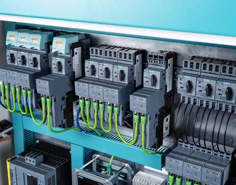
maintenance. This uses artificial intelligence to examine fluctuations in current for anomalies that indicate a defect, for example. This significantly increases the planning reliability for maintenance, availability and cost-effectiveness of the system.
Thanks to the complete integration in TIA, the user always receives current status information in their operating software and,

SOURCE: SIEMENS
when using special apps such as "Node-RED", also a dashboard for quickly identifying bottlenecks. This avoids failures and increases the availability of the system.
The intelligent SIRIUS 3RC7 link modules integrate perfectly into the compact SIMATIC ET 200SP IO system. However, all other common automation systems can also be used. Up to 16 load feeders can be connected to each BA-Send module bus adapter in order to benefit from the simple commissioning, individual scalability and the maximum flexibility offered by the SIMATIC ET 200SP.
In conjunction with SIRIUS switching devices and the compact SIMATIC ET 200SP IO system for the control cabinet, intelligent SIRIUS 3RC7 link modules ensure secure and efficient data exchange between OT and IT. By expanding the existing SIRIUS portfolio (modular system) with the new intelligent SIRIUS 3RC7 link module, a new, further developed product is created - the SIRIUS Intelligent Load Feeder.
The SIRIUS Intelligent Load Feeder is a pre-assembled, digital feeder consisting of a SIRIUS 3RV2 circuit breaker, a SIRIUS 3RT2 contactor and the intelligent link module.
Rugged MPC-3000 family panel computers target reliable operation in harsh industrial environments.
MOXA HAS ANNOUNCED THE LAUNCH OF ITS MPC-3000 Series panel computers. Designed to address the diverse needs of industrial environments, the MPC-3000 panel computers offer a range of screen sizes, a robust feature set, and industry certifications aimed at reliability, durability, and versatility in demanding operating environments.
According to Business Research Insights, the global industrial panel PC market is set to experience substantial growth, with the market size projected to increase from USD 1.11 billion in 2024 to USD 1.54 billion by 2032 and exhibit a CAGR of 4.2%. The AsiaPacific region leads this growth, driven by an increasing demand for advanced, reliable computing solutions in industrial sectors. The MPC-3000 Series industrial panel PCs, with their adaptability and industrial-grade features, are a strong contender in this expanding market.
The MPC-3000 panel PCs, powered by Intel Atom® x6000E processors, offer exceptional versatility with six distinct series that feature screen sizes ranging from 7 inches to 15.6 inches. Designed for use in harsh industrial environments, these panel PCs come with advanced touchscreen functionality and sunlight-readable displays, and support wide-temperature operations, making them well-suited for a variety of outdoor applications. Whether deployed in oil and gas fields, marine operations, outdoor applications, or other demanding settings, the MPC-3000 panel PCs are reliable and efficient, even in tough conditions.
Furthermore, the modular design of the rugged panel PCs simplifies maintenance and minimizes downtime in demanding industrial environments. By offering a cableless approach on both the front and rear panels, the design reduces complexity, making component replacement quick and easy.
This streamlined, modular architecture enhances operational efficiency, ensuring maintenance tasks cause minimal disruption.
Designed specifically for industries such as oil and gas, marine, and outdoor applications, the MPC-3000 panel PCs are certified to meet the rigorous demands of extreme operating environments. Certifications include Class I Division 2, ATEX Zone 2, and IECEx Zone 2 for hazardous locations, as well as DNV,
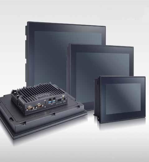
Moxa MPC-3000 panel PCs, powered by Intel Atom® x6000E processors, offer exceptional versatility with six distinct series that feature screen sizes ranging from 7 inches to 15.6 inches.
IEC 60945, and IACS standards for maritime operations.
These certifications, along with the panel PCs’ rugged construction, ensure dependable performance and safety, making them an ideal choice for mission-critical applications in challenging settings.
Control systems in the field may include a number of different PLCs and SCADA systems. Moxa's extensive experience in HMI hardware solutions enable them to offer panel computers that work smoothly with different SCADA software such as:
• FactoryTalk View SE/ME
• GE iFIX
• Wonderware InTouch
• SIMATIC WinCC
• Ignition
• PcVue
• TwinCAT
• FreeSCADA
MPC-3000 Series highlights
Features include:
• Wide panel sizes from 7 to 15.6 inches
• Intel Atom® x6211E dual-core or x6425E quad-core processor
• -30 to 60°C operating temperature
• Fanless design, no heater required
• 400/1000 nit sunlight-readable display
• Glove-friendly multi-touch screen
• DNV, CID2, ATEX Zone 2, and IECEx compliant
For product information and technical specifications of the MPC-3000 panel computers, visit the MPC-3070W, MPC-3100, MPC-3120, MPC-3120W, MPC-3150, and MPC-3150W product pages.
Moxa
Learn More
EtherCAT Box features an accelerometer and gyroscope in one compact, IP67-rated device.
THE EP3751-0260 ETHERCAT BOX PROVIDES extremely accurate detection of acceleration and rotational motion. With this IP67-rated module, engineers can optimize positioning and measurement in wide-ranging applications.
As a replacement for multiple previously separate devices, the machine-mountable EP3751-0260 connects an acceleration sensor with an inertial measurement unit (IMU), such as a gyroscope, in a housing that measures just 30 x 86 x 22 mm. As such, this unit can detect shock, vibration, and tilt, and deliver all measured data as pre-processed values and raw sensor data.
Based on EtherCAT Box technology, the module integrates an ultra-low-noise, three-axis accelerometer with a 20-bit resolution and an adaptable measuring range of ±2, ±4, and ±8 g. The sampling frequency is 4 kHz. The built-in sensor is suitable for applications where low frequencies need to be monitored with as little noise as possible for monitoring building work, bridge monitoring, robotics, or condition monitoring.
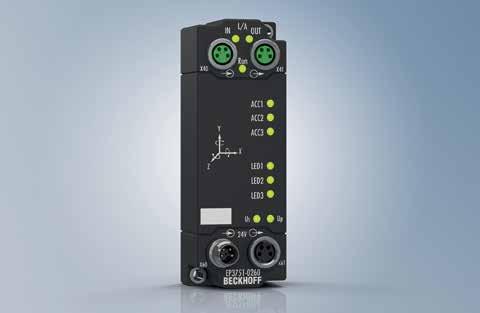
The EP3751-0260 also features a low-noise, temperature-stable three-axis MEMS gyroscope sensor (6DoF IMU) to record even complex rotational motion. These two sensors enable high-precision measurement for a wide variety of motion applications using just one versatile I/O box module.
The high-performance EtherCAT connectivity ensures virtually delay-free transmission to the evaluating measuring system.
HMS Networks expands range of embedded communication interfaces with Anybus CompactCom B40 Mini.
The Anybus CompactCom B40 Mini is a soldered-on communication interface complements the Anybus CompactCom 40 series.
The Anybus CompactCom family offers a range of ready-made communication interfaces that can be embedded into any industrial machine or device, enabling connectivity to all major industrial networks. The new Anybus CompactCom B40 Mini adds a soldered-on option to the existing lineup of modules and pluggable bricks.
Each range in the Anybus CompactCom family has distinct characteristics, making them ideal for different industrial applications.
The Anybus CompactCom B40 Mini includes the following features:
Compact design: Soldered directly onto the device’s carrier board, it’s 30% smaller than the pluggable brick, making it ideal for small devices.
Efficient manufacturing: Delivered in tapeand-reel and ready for automated production

through pick-and- place and Surface-Mount Device (SMD) soldering, it’s designed for high-volume and cost-effective production.
Versatile network support: Preloaded with PROFINET, Ethernet/IP, POWERLINK, EtherCAT, Modbus TCP, and BACnet Industrial
Ethernet networks, or delivered pre-set for a specific network.
HMS Networks Learn More
Smart switches offer easy and secure network automation.
Moxa’s SDS-3000/G3000 smart switches have been developed for users who want to upgrade from unmanaged to managed switches without sacrificing usability. With support for common industrial protocols such as PROFINET, Modbus, and EtherNet/IP, these switches allow an easy integration into existing networks while providing advanced safety functions like VLAN support and port control.
An intuitive web GUI makes configuration easy, so that networks can not only be installed quickly, but also monitored and maintained in a secure way. The new models in the SDS Series are compact and ideal for space-saving applications such as control cabinets. They are equipped with 6, 10 and 12 ports and complement the existing 8- and 16-port models.
The Layer 2 managed switches in the EDS-4000/ G4000 Series are characterized by industrystandard reliability, network redundancy, and safety functions. For example, the series is certified according to IEC 62443-4-2 Security Level 2. Other industrial certifications include NEMA TS2, EN 50121-4, IEC 61850-3/IEEE 1613 Class 1, DNV and ATEX, Class I Division

2. The EDS-4000/G4000 Series also features Turbo Ring and Turbo Chain, which enable fast network recovery and ensure smooth operation.
Most recently, the EDS-4000/G4000 Series also supports MX-NOS firmware version 4.0, which provides additional safety functions,
diagnostic options, and enhanced features to future-proof industrial networks.
Axioline E I/O generation for control-cabinet-free automation and digital signal processing.
With the two new IO-Link device I/O boxes, AXL E IOL DI16 M12 6M and AXL E IOL DIO8/8 M12 6M, Phoenix Contact is extending the portfolio of the new Axioline E I/O generation for control-cabinet-free automation to include devices for digital signal processing.
Featuring increased IP65/IP67/IP69 degree of protection and a fully encapsulated zinc die-cast housing, the new Axioline E I/O generation is designed for direct use in a machine under particularly harsh ambient conditions. The extended temperature range and strong resistance to environmental influences allows for use in many different applications. All devices enable flexible field wiring with proven M12 screw connectors or the new M12 push-pull fast-connection technology.
The IO-Link technology provides globally standardized consistent communication from the controller right through to the sensor/ actuator level. Consisting of an IO-Link master and an IO-Link device, an IO-Link system can be integrated into all common fieldbus and automation systems. IO-Link enables access to process data, diagnostic
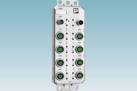
data, and device information, as well as device parameters of the IO-Link devices.
The installation concept between an IO-Link master and an IO-Link device is based on a simple unshielded 3-conductor
standard cable.
Phoenix Contact Learn More
IntraVUE provides more secure, higher performance and more efficient production control networks.
REAL TIME AUTOMATION HAS INTRODUCED IntraVUE™, a powerful monitoring and support tool designed to revolutionize the way maintenance techs and controls engineers manage critical, real-time production networks.
"In my three decades in automation, I've never seen a product that can improve manufacturing efficiency, performance, and security like IntraVUE," stated John Rinaldi, CEO of Real Time Automation.
By shifting from a reactive to a proactive approach, IntraVUE empowers teams to significantly improve asset management, uptime, and overall network performance. With IntraVUE, manufacturers can:
Identify and Resolve Network Issues Instantly: IntraVUE continuously monitors all network switches and devices, instantly detecting and alerting manufacturers to critical issues such as failed connectors, duplicate IP addresses, VLAN misconfigurations, auto-negotiation failures, and overloaded segments.
Optimize Network Performance: IntraVUE builds Key Performance Indicators (KPIs) for the entire network, individual switches, and devices, enabling manufacturers to proactively identify and address potential performance bottlenecks before they impact production. By identifying and addressing network issues and inefficiencies, IntraVUE helps manufacturers maximize production efficiency and minimize downtime.
Uncover Hidden Network Insights: IntraVUE's time machine feature allows manufacturers to review network activity from months, weeks, days, or hours ago, providing invaluable insights into past network events like temporary connections or machine slowdowns.
Meet Critical Cybersecurity Standards: IntraVUE helps manufacturers comply with stringent cybersecurity regulations like the European Cyber Resilience Act (CRA) and Cybersecurity Maturity Model Certification

(CMMC) 2.0 by providing a comprehensive asset list, including device identities, locations, and connection history. Manufacturers can identify and mitigate security risks, protecting their critical production networks from unauthorized access and cyberattacks.
Gain unprecedented visibility: IntraVUE provides real-time insights into network health, device performance, and potential issues, enabling proactive troubleshooting and maintenance while minimizing downtime.
Enhance asset management: IntraVUE's comprehensive asset tracking capabilities enable manufacturers to understand what network devices they have, how they are

all connected and the version levels of each device on the network.
Customer case in point
"IntraVUE has proven to be an invaluable asset for our operations," said the head production control engineer at a larger timber company. "The timely alerts and actionable insights provided by IntraVUE enabled us to prevent a costly outage and maintain our production schedule."
When emails alerted the team about ping failures on a machine, they were able to quickly investigate and discover a failed network interface card (NIC). By proactively replacing the NIC, downtime and a production interruption were avoided.
Architected to solve the staggering number of manufacturing production control network challenges including the alarming vulnerabilities to cyberattacks, IntraVUE automatically detects all Ethernet-connected devices and assembles them into a connection tree map of the physical layer network infrastructure and a comprehensive list of every asset connected to your network, even those connected momentarily, bolstering a network's cybersecurity.
Visit Website
Rockwell Automation brings new wireless interfaces, new edge to Stratix® 4300.
The Stratix® 4300 Remote Access™ Router solution now has both Wi-Fi and LTE (cellular) wireless options available. These options include Ethernet only (existing product with 2 or 5 ports), Ethernet and Wi-Fi (2 or 5 ports), Ethernet and LTE (2 or 5 ports), and Ethernet, Wi-Fi, and LTE (2 or 5 ports).
The addition of these wireless interfaces for Wi-Fi and LTE (cellular) allows customers to use the Stratix 4300 in applications where a physical Ethernet connection may be difficult or not desired. Wireless options on the Stratix 4300 router help users reduce downtime, maintain business continuity, and enable a productive workforce.
Stratix 4300 will continue to be a dedicated platform for the FactoryTalk® Remote Access™ solution, which enables VPN connectivity with industrial networks, for increased visibility across your plant. All Stratix 4300 units come pre-installed with FactoryTalk Remote Access.
Supporting accessories such as antenna and mounting options are available to plants with flexible locations for their Stratix 4300.

Some of the distinct benefits to running FactoryTalk Remote Access with the Stratix 4300 include a NAT 1:1 for routers which maps an internal address (LAN) to an external address (WAN or VPN) and the ability to conduct remote updates, allowing
X DIAS I/O system can be integrated into OEM design of wiring boards – saving wiring time and costs.
With X-DIAS, SIGMATEK is launching an I/O system for customized wiring boards as addition to the established S DIAS automation system. X-DIAS increases flexibility for series machine builders with medium and high volumes and delivers minimal wiring within the machine. The modules can be easily integrated into the OEM design of wiring boards – saving wiring time and costs.
The new I/O series is based on the proven S-DIAS system, so it is just as robust and vibration-resistant. At 12.5 x 102 x 63 mm, the X-DIAS modules are even more compact in depth. Thanks to an electromechanical adaptation, it is possible to plug the modules individually and directly onto wiring boards.
The X-DIAS modules are equipped with an LED status display and coding pins. The corresponding drill holes are located on the PCBs at the corresponding module position. This mechanical coding prevents incorrect placement and wiring. It's very simple: Click & Go.
Using the wiring boards eliminates the need for manual single-core wiring.
In addition, the required fuses, cut-off relays and the necessary intermediate wiring can be
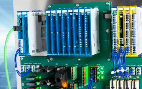
placed on the wiring board. This significantly reduces the wiring and commissioning effort. Standard bus systems are available for communication with the control system (e.g. Industrial Ethernet VARAN bus). In addition to the wiring boards, the complete S-DIAS and P-DIAS module range can also be used, for example for variants of the basic machine.