


Single Pair Ethernet and Ethernet Advanced Physical Layer (APL) are new technologies that are transforming by providing the slim, lightweight yet powerful infrastructure for Ethernet to enable industry to digitize at the field level and take the next big step into IIoT.
According to the SPE Industrial Partner Network, "Single Pair Ethernet (SPE) provides the necessary infrastructure for the Industrial Internet of Things (IIoT). With SPE, Ethernet can communicate from the cloud to the field level in a space- and cost-efficient way for the first time."
Single Pair Ethernet (SPE) describes the transmission of Ethernet via only one pair of copper wires. In addition to data transmission via Ethernet, SPE also enables simultaneous power supply to end devices via PoDL - Power over Data Line. Until now, two pairs of copper wires were necessary for Fast Ethernet (100MB) or four pairs of copper wires for Gigabit Ethernet. SPE is now opening up completely new possibilities and fields of application for industrial Ethernet.
Ethernet APL defines a two-wire Ethernet solution for process automation and hazardous locations, based on IEEE and IEC standards. According to the Ethernet-APL trade organization, the technology enhances the value generated by process plants by bringing Ethernet technology and high-speed communication out into the field. The goals is to dramatically simplify installation, configuration and maintenance of instruments and automation technology and is designed for a workforce trained in IP technology.
In this issue of the Industrial Ethernet Book, we devote a wide range of editorial coverage to these important topics that are changing the landscape of Industrial Ethernet.
On page 6, read about how Ethernet-APL digitization is impacting the process industries. Ethernet Advanced Physical Layer is bringing digitization into every corner of process control plants. Long cable lengths, explosion protection and interoperability is enabling continuous and transparent communication across all hierarchy levels, and is paving the way for demanding IoT applications in the process industry.
This lead story is followed by a series of technology articles that explore Ethernet-APL: Single Pair Ethernet in Hazardous Environments (page 11), Achieving Net Zero CO2 Emissions with Single Pair Ethernet (page 14) and General Purpose Single Pair Ethernet for Process Instruments (page 16).
We live in exciting times in the development of Industrial Ethernet, as it continues to provide advanced technology in manufacturing. Al Presher
The next issue of Industrial Ethernet Book will be published in July/August 2024. Deadline for editorial: July 12, 2024 Advertising deadline: July 12, 2024
Editor: Al Presher, editor@iebmedia.com
Advertising: info@iebmedia.com
Tel.: +1 585-598-6627
Free Subscription: iebmedia.com/subscribe Published by IEB Media Corp., 1247 Anthony
New open standard initiative for interoperability, called Margo, aims to unlock interoperability at the edge–a key layer of Industrial IoT ecosystems where plant data is transformed into AI-powered insights.
ABB HAS CO-LAUNCHED AN INTEROPERABILITY initiative to unlock Industrial IoT insights for more efficient and sustainable industry.
• Margo, a new open standard initiative for interoperability, will address key roadblocks to digital transformation
• The initiative is hosted by the Linux Foundation and driven by a founding group of industrial automation solution providers, including ABB Process Automation and ABB Machine Automation (B&R)
• Margo aims to unlock interoperability at the edge – a key layer of Industrial IoT ecosystems where plant data is transformed into AI-powered insights to drive efficiency and sustainability
At the Hannover Messe on April 23, 2024, founding members ABB (including B&R), Capgemini, Microsoft, Rockwell Automation, Schneider Electric (including AVEVA) and Siemens announced collaboration on a new initiative to deliver interoperability for Industrial IoT ecosystems.
Hosted by the Linux Foundation and open to further interested parties, the Margo initiative draws its name from the Latin word for 'edge' and will define mechanisms for interoperability between applications, devices and orchestration software at the edge of industrial ecosystems. In particular, Margo will make it easy to run and combine applications from any ecosystem member on top of the hardware and runtime system of any other member.
Margo aims to deliver on its interoperability promise through a modern and agile open-source approach, which will bring industrial companies increased flexibility, simplicity and scalability as they undergo digital transition in complex, multi-vendor environments.
“Mastering efficiency, flexibility and quality faster than competitors is key to success in today’s industrial world,” said Bernhard Eschermann, CTO, ABB Process Automation. “Digitalization can help deliver on these benefits, but digital ecosystems require a robust, secure and interoperable framework at the edge, connecting operations and information technologies. For ABB, a longstanding advocate of open automation systems, driving a forward-thinking

MQTT has been identified as a key enabler for IIoT projects, while data suggests Sparkplug is an emerging data framework (www.hivemq.com).
collaborative initiative like Margo is key to achieving this goal.”
Interoperability is key to digital transformation at scale
"The more sources you get data from, the better the decisions you can make," explained Florian Schneeberger, CTO of ABB's Machine Automation division (B&R).
"Yet, while the benefits of digitalization increase with scale, so do the challenges of navigating heterogeneous industrial ecosystems. That's why interoperability is so crucial to unlocking the full potential of digitalization. It empowers organizations to adopt and scale Industrial IoT solutions at full speed without large teams of IT specialists," he added.
In March 2024, ABB became a member
of the Linux Foundation. This will enable the company to further enhance efforts in promoting open community collaboration, helping unlock innovation and enable better products and experiences for customers. This further strengthens ABB’s commitment to open standard based systems.
In a live panel discussion at the Hannover Messe, representatives from the six founding members met to present their vision for edge interoperability in the Industrial IoT and appeal to like-minded industry peers to join the community and contribute to building a meaningful and effective standard.
A recording of the panel discussion will be available at www.margo.org.
News by ABB Machine Automation/B&R


Full automation of all processes and plants
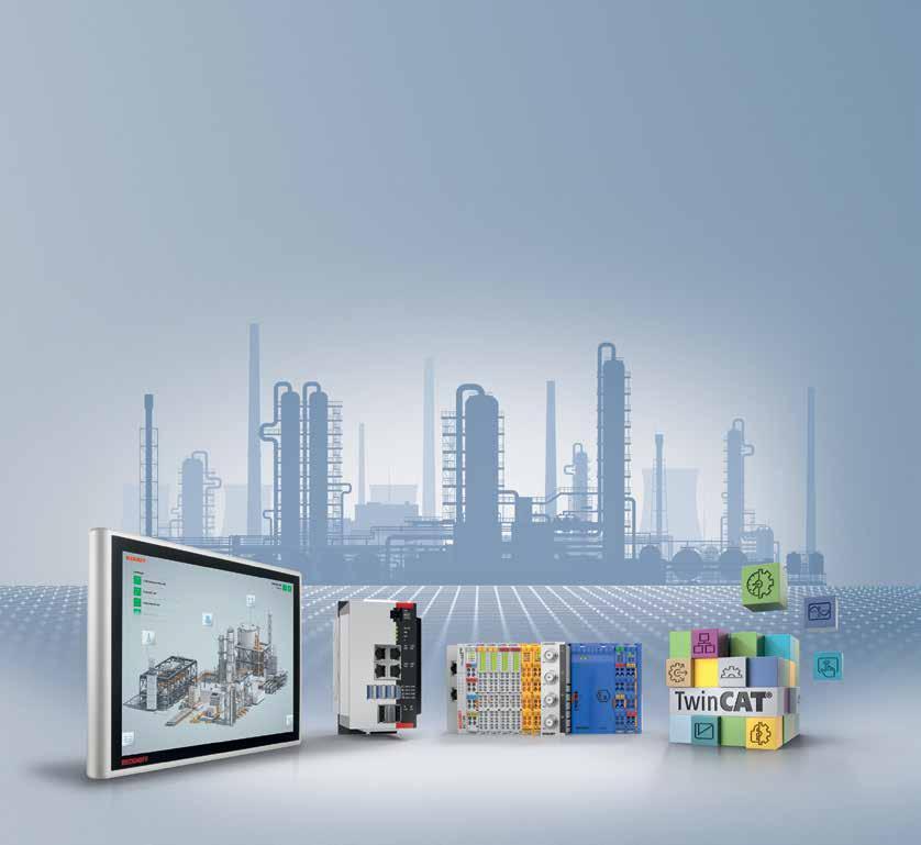
integration of all control functions into a single hardware and software platform control and cable redundancy to increase system availability
extensive portfolio of components for explosion protection
EtherCAT modules with intrinsically safe interfaces for the direct connection of field devices up to zone 0/20
support for typical industry standards such as NAMUR, HART, and FDT/DTM
seamless integration of MATLAB®/Simulink® and Labview in TwinCAT
TwinCAT MTP for system modularization


Ethernet Advanced Physical Layer is bringing digitization into every corner of process control plants. Long cable lengths, explosion protection and interoperability is enabling continuous and transparent communication across all hierarchy levels, and is paving the way for demanding IoT applications in the process industry.

ETHERNET ADVANCED PHYSICAL LAYER (APL) is a ruggedized, two-wire, loop-powered Ethernet physical layer that uses 10BASE-T1L plus extensions for installation within the demanding operating conditions and hazardous areas of process plants.
Ethernet-APL technology enables a direct connection of field devices to Ethernet-based systems in a way that process industries can benefit from a convergence of their OT and IT systems. Utilizing a switched architecture eliminates any unwanted interference between devices connected to the same network.
Ethernet-APL adopts technologies and options already established in the field of process automation. This includes the proven
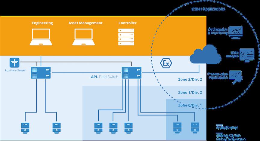
trunk-and-spur topology shown in the figure above with the ability to power up to 50 field devices with up to 500 mW each. Widely used and established cable infrastructures are specified to support the migration in brownfield installations to Ethernet-APL.
The basis of the technology is that it offers a series of key benefits:
Only Two Wires: By using two conductor cabling, that may be already be installed in a facility, Ethernet-APL can offer an attractive technology upgrade value proposition.
Conformance: Devices and components are required to undergo conformance testing to assure that all critical Ethernet-APL features are implemented properly.
Familiar Installation: Using proven FISCO practices helps assure proper installation — first time, and every time.
Ethernet-APL technology
Since Ethernet itself is a broadly accepted standard for wired digital communications that is standardized in IEEE 802.3, its wide acceptance in industries and households created an eco-system of standardized tools for installation, troubleshooting, and diagnostics.
According to the FieldComm Group, “Ethernet-APL is an enhanced physical layer for single-pair Ethernet (SPE) based on 10BASET1L. It communicates via a cable


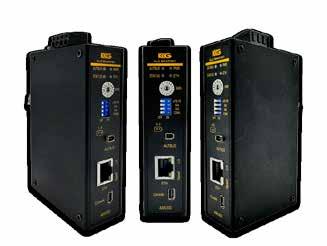
AUTBUS is a new industrial broadband fieldbus, standardized as IEC 61158 type 28. It connects up to 254 nodes over 500 meters at 100Mbit/s using a single twisted-pair cable. The system utilizes OFDM technology for robust communication and supports data tunneling for various protocols.
The AUTBUS Converters to Ethernet/CAN/RS485
Suitable for applications such as factory automation, public transport, building automation, traffic control systems and EV charging station.


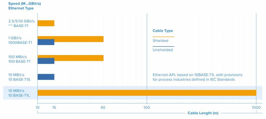
length of up to 1000 m at 10 MBit/s, fullduplex, which is more than 300 times faster than current technologies, such as HART
or fieldbus. It is the logical extension for Ethernet and provides the attributes required for reliable operation in the field of a process
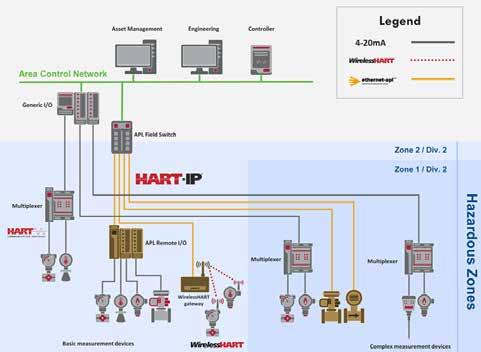
Ethernet-APL relies on powered field switches, which convert plant Ethernet—connected to controllers or other computing assets—to intrinsically safe Ethernet-APL, while also injecting power into the physical layer to meet the needs of remote I/O, instrumentation, and other field devices. Cable runs can be up to 1,000 meters long.
The architecture provides a simple way to get started with Ethernet-APL by installing just two cables and two pieces of expandable infrastructure. Traditional field instruments can be connected to EthernetAPL remote I/O, and the architecture can be expanded as new devices become available and user needs grow.
SOURCE: FIELDCOMM GROUP
plant. Ethernet-APL is a physical layer that will be able to support EtherNet/IP, HART-IP, OPC-UA, PROFINET, or any other higher-level protocol.”
Additional key benefits of Ethernet with an Advanced Physical Layer (Ethernet-APL) are the ability to enable long cable lengths and explosion protection via intrinsic safety with communication and power over two wires. Based on IEEE and IEC standards, Ethernet-APL supports any Ethernet-based automation protocol and will develop into a single, long-term stable technology for the entire process automation community.
Study identifies industry readiness and application targets for Single Pair Ethernet and Ethernet-APL technology.
Dr. Al Beydoun, ODVA President and Executive Director told the Industrial Ethernet Book that ODVA commissioned a study on Single Pair Ethernet (SPE) to understand the level of industry readiness, perceptions, and opportunities for this new technology.
The study was conducted in June 2023 and resulted in close to 250 completed surveys from a broad representation of the market, including system integrators, discrete manufacturing, food/pharmaceutical companies, and utilities. The leading roles of survey participants were individual contributors/engineers and mid-level managers, meaning that those who would be directly engaging with SPE the most had the strongest voice. The median company in the survey was mid-sized with $10-$100
million dollars in revenue and between 100 and 500 employees. While North America was the predominant respondent location, Europe and Asia made up a third of the total respondents.
The survey results showed that the top applications likely to benefit from SPE are remote, hard to reach locations; highly
distributed field devices; simple, low-cost devices; and hazardous areas. Additionally, respondents stated that ability to provide power & communication via same wire pair, increased speed/bandwidth, and simplified cabling were the top three anticipated benefits of SPE.
Furthermore, 42% of respondents were
willing to make moderate or significant investments to achieve the benefits of SPE while 87% of respondents were willing to make a minimal investment. Lastly, 44% of respondents believed that their organization will adopt SPE in 4 years or less.
“The results of the SPE survey are very encouraging and show that the opportunity

“Technology solutions such as Ethernet-APL (10BASE-T1L) will support hazardous areas via 2-Wire Intrinsically Safe Ethernet (IEC TS 60079-47:2021) and remote, hard to reach locations with support of Type A Fieldbus Cable (IEC 61158-2) with lengths of up to 1,000 meters. ODVA has completed all of the necessary specification work to make EtherNet/IP ready for Ethernet-APL," -- Dr.

“The
for the technology is now. Another takeaway from the survey is that there are opportunities to further grow and develop the SPE market via creating and widely disseminating tutorials, case studies, cost/benefit analyses, and planning and implementation guides to educate potential users,” Beydoun said.
According to Beydoun, SPE addresses the IIoT technology trend of connecting more devices than ever before via Ethernet, which enables remote parametrization and device monitoring as well as the availability of additional data that can be used for operations visibility and optimization.
“According to the ODVA commissioned survey, the top-rated applications show that there are many different uses for SPE. Technology solutions such as Ethernet-APL (10BASE-T1L) will support hazardous areas via 2-Wire Intrinsically Safe Ethernet (IEC TS 60079-47:2021) and remote, hard to reach locations with support of Type A Fieldbus Cable (IEC 61158-2) with lengths of up to 1,000 meters. ODVA has completed all of the necessary specification work to make EtherNet/ IP ready for Ethernet-APL,” Beydoun said.
Additionally, simple, low-cost devices such as contactors and push buttons can be connected via EtherNet/IP In-Cabinet SPE (10BASE-T1S). EtherNet/IP can be made available in-cabinet via a bus solution that uses a multidrop network and control power cable that spans a single cabinet. EtherNet/ IP In-Cabinet uses one interface per device and one switch port across multiple devices to reduce both commissioning and hardware cost. Further, highly distributed field devices will
be supported via general purpose SPE. ODVA is currently working on general purpose SPE for EtherNet/IP to support additional discrete applications.
Engineering challenges
SPE allows engineers to better handle complex tasks like device commissioning that can be done significantly quicker via Ethernet as well as troubleshooting that is aided by descriptive diagnostics. Additional bandwidth means that devices that previously only supported one process variable can now support multiple via the 10 Mbit/s speeds of Ethernet-APL, as an example. Ethernet standards such as PA-DIM and OPC UA, which are both supported by EtherNet/IP, also allow standardization of data exchange between the device, edge and cloud level for optimization and analysis powered by Artificial Intelligence.
“The significant challenges that are addressed by SPE across discrete, hybrid, and process industries show why ODVA is such as strong proponent of the technology,” Beydoun added. “ODVA has supported Ethernet-APL and has finalized all the necessary specifications and conformance testing for this technology. With market demand indicating customer desire for EtherNet/IP devices over Ethernet-APL, device vendors will be coming to market with products in response to this need. In addition, ODVA has finalized specifications for the use of EtherNet/IP in-cabinet, and industry can expect conformance testing and solutions to be available soon.”
Beydoun said that Ethernet-APL will
address the needs of the hybrid and process industries who require hazardous area protection and long cable lengths. The hybrid industries such as food/beverage are likely to lead the way in terms of Ethernet-APL adoption for devices such as level and temperature sensors. In-Cabinet EtherNet/IP looks to be adopted across all industries because the wiring savings compared to a traditional cabinet along with the additional diagnostics are broadly beneficial.
“Process and hybrid industries are probable to be among the first users though due to the prevalence of stainless-steel cabinets for wash down applications and outdoor environments. General purpose Ethernet is targeted toward the discrete industries such as automotive that have already shown a strong interest in digital connections to the sensor level. Distribution centers, airports, and factories that use long fieldbus cable lengths to support proximity sensors and gate actuation are also good candidates for general purpose SPE,” Beydoun said.
“The impact of SPE on manufacturing operations will be very positive due to the additional data, ability to monitor and make changes remotely, and the capability to easily add devices to the network over time. The benefits of SPE will make it possible for controls engineers and plant managers to better handle the challenges of improving quality, output, and profitability in the face of rising costs, increased focused on sustainability, and the shortage of workers,” he added.
Al Presher, Editor, Industrial Ethernet BookEthernet-APL is based on IEEE 802.3cg and allows field devices to perform critical process automation tasks in severe Zone 1 locations. The technology will form the basis of future digitalization efforts and applications globally offering a speed of 10 Mbits per second, a reach of 1,000 meters and intrinsically safe protection.
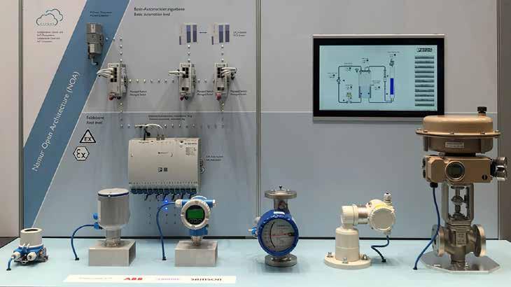
FIELD DEVICES IN PROCESS AUTOMATION applications must coordinate process values (flow, pressure, level, temperature, and process analytics) with intelligent control valves in the most dangerous and severe environments, known globally as hazardous locations. Users of the technology work in areas defined areas as Zones or Divisions, depending on their location in the world.
Ethernet-Advanced Physical Layer (APL for short), based on IEEE 802.3cg, allows the latest generation of field devices to perform these critical process automation tasks, even in the most severe locations, such as Zone 1.
As Ethernet-APL is implemented in process field devices, it will form the basis of future digitalization efforts globally. With a speed of 10 Mbits per second, a reach of 1,000 meters (3,280 feet), and intrinsically safe protection, Ethernet-APL promises a host
of new possibilities for existing and future applications.
Ever since electronics replaced pneumatics for most process industry applications, the de facto industry standard has become 4-20 mA signals over a twisted shield pair of wires powered with 24 V DC.
The 16-mA difference in the signal allows for a single process variable value to be sent or received over long distances. The 24 V DC-powered loop with a floating zero-point can detect a wire break in the signal loop when less than 4 mA is present.
The signal loop distance of up to 1,000 meters can easily exceed the 100-meter limitations of regular office Ethernet and is connected at the end opposite the process field device to a controller or remote I/O station.
Many process field devices can access additional device information via the HART communication protocol. This data can be sent and received without compromising the important primary variable (PV) device signal. The signal is sent at 1,200 bits per second using the Bell 202 standard.
Ethernet, with its classic 10/100 data-rate capability, offers significant speed advantages. And the 10 Mbits per second speed is a giant leap for the market.
Where Ethernet-APL comes from
In June 2021, 12 well-known manufacturers in the process automation industry presented the first Ethernet-APL prototypes as part of the virtual ACHEMA Pulse event. This represented an exciting upgrade to the existing commercially available technology. Previously, the more complex process field devices required close to 10 minutes for
device download, update, or programming scans when using HART. Similar Ethernet-APL field devices, however, could execute the same steps in mere seconds.
The transition of field devices running with serial communication to fully bidirectional digital solutions based on two-wire Ethernet was immediately evident. The market fully appreciates what this disruptive innovation can offer: improved access, accelerated efficiency, and optimized process plant capability.
However, more can be understood about the development of this unique technology. The "APL Project" team consists of the four influential standards development organizations (SDOs) involved in process automation: PI International (PROFINET), ODVA (EtherNet/IP), FieldComm Group (HART-IP), and OPC Foundation (OPC-UA). In addition, it also includes 12 leading manufacturers, who represent the combination of advanced process controllers, infrastructure switches, and best-in-class field devices required to build a working system.
The APL Project involves the collaboration of customer input, industry knowledge, and process safety site standards, coupled with global standards, laboratory testing, and third-party certification. In addition, the special PHY chips needed to develop the APL technology are now available from companies like Analog Devices and Texas Instruments.
The enhancements and modifications to the original IEEE 802.3cg standard were application- and safety-related. The ubiquitous RJ45 works well in the office environment. However, a more rugged connector – like the one used for many decades in 4-20mA, HART, and Fieldbus installations – was chosen and is used on the port connections of both the APL switch and the field devices.
The voltage levels in the IEEE 802.3cg specification require more precise control of voltage, current, and total power in the loop. Even the capacitive, inductance, and resistive values must be defined and synchronized to ensure that no spark is ever present in a process automation application. The energy limitations were already incorporated into prior Fieldbus standards and require a state-of-the-art protection method known as Intrinsic Safety. The result was the new IEC TS 60097-47 Technical Specification, with the working name of 2-Wire Intrinsically Safe Ethernet or 2-WISE.
Ethernet-APL promises to replace 4-20 mA technology in process automation in the coming years with its typical Industry 4.0 and Ethernet capabilities. A task force
of manufacturers and end-users has already defined a dozen new projects that will use APL.
While the 4-20 mA signal only allows a single measurement value, the APL field device will provide multiple data sources for plant operators, increasing the efficiency and capabilities of projects and processes. In addition to maintenance personnel, process personnel will have equal access to the field devices to monitor the process with near real-time data.
As field devices become increasingly intelligent and powerful, there has been no sensible and practical way to quickly access the amount of information now possible. Industry insiders know that protocols such as HART, PROFIBUS PA, and FOUNDATION Fieldbus have promised "digital" capabilities but only at limited speeds.
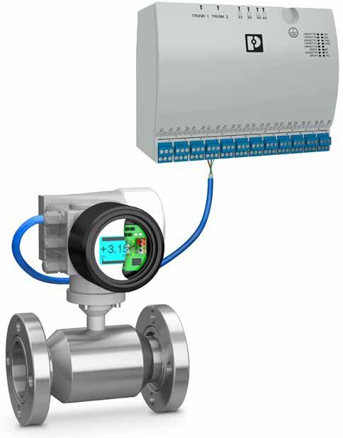
In the distribution cabinet, port connections on the switch are connected to spurs on the APL devices. So, as PROFIBUS PA devices are replaced with newer APL devices, the APL field switch offers a migration path from PROFIBUS PA to PROFINET APL devices. Here, the APL connection of 10 Mbits per second provides ten times faster access to internal data and process values of a comparable PROFIBUS PA device. There are field switches for use in modular units, such as skids and production lines in the pharmaceutical and food and beverage industries.
So, using fiber optics, a field switch can also be installed in processes where there is a significant distance between the controller and field devices. The 200-meter spur length per connection allows a lot of flexibility on the field device side.
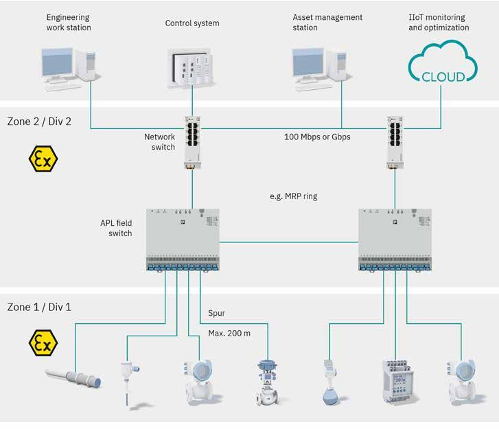
Phoenix Contact is developing infrastructure components required for an APL network, such as the APL field switch. The first device to be launched is a 24-port APL field switch for Zone 2 installation. This first APL field switch therefore comes with four uplink ports – two copper, and two SFP fiber. Each of the 24 ports is an Ex ia (the most stringent) APL port with 200-meter (656-foot) length capability and the Power Class A of 540 mW, with a little more power available if needed.
With an integrated web-based manager, the switch's 24 ports can support both APL and PROFIBUS PA field devices, and initial customer response has been extremely positive.
Since many of the APL device types are not yet available, initial projects will be based on a mix of APL and PROFIBUS PA devices. The PROFIBUS PA connection is only
possible with a PROFINET controller on the uplink side.
Phoenix Contact launched its first managed switch product line almost two decades ago, and the latest generation – the FL 2000 managed switch – was introduced in 2018. This experience led to the development of the first Ethernet-APL switch, which shares this heritage and joins an extensive range of products.
The managed switch portfolio also includes an SPE switch as the entrée into both IEEE 802.3cg versions.
What's next for Ethernet-APL?
ACHEMA, the world's largest process automation show, will showcase many certified Ethernet-APL products in June 2024. The number of manufacturers now developing APL products has also expanded beyond the original 12.
Users of the new technology should expect a portfolio of field devices (measurement and control), controllers, and infrastructure components such as power and field switches.
In addition, Ethernet-based process safety and cybersecurity will also be a part of the Ethernet-APL breadth of technologies moving forward.
For more information on the APL Project, a white paper is available at www. ethernet-apl.org.
For more information on the technology of Ethernet APL at Phoenix Contact, visit phoe. co/Ethernet-APL.
Arnold Offner, Strategic Marketing Manager –Automation Infrastructure, Phoenix Contact Development and Manufacturing, Inc.
Single-pair Ethernet can help the industry meet net zero goals while supporting AI-based automation in a secure and cost-effective manner. SPE enables long-reach connectivity to the edge for both greenfield and retrofit installations, making it a critical tool for seamless data transfer between IT and OT domains.
Converging systems allow data visualization through a single pane of glass, which enables energy savings when used alongside automation and AI/ML.
TO MEET NET ZERO CO2 EMISSION GOALS, the building sector needs to modernize its communication infrastructure. This article shows how single-pair Ethernet, specifically 10BASE-T1L, enables the easy retrofitting of buildings using legacy links like RS-485 to improve digitization, enable automation, improve security, and substantially lower energy consumption to achieve greater sustainability.
To address climate change and sustainability, over 90 countries are actively developing net zero CO2 emission policies. In short, net zero is achieved when human-based CO2 emissions are both reduced and counterbalanced through other activities.
A fundamental factor in reaching net zero is the reduction of CO2 emissions across all industries. However, according to the International Energy Association (IEA), the building sector is not on track to meet global 2050 net zero CO2 emission goals. Specifically, 2030 goals target 35% less energy consumption per square meter compared to 2021. As buildings account for 30% of global energy consumption today, there is concern that emission goals will
not be met unless the industry takes specific action to digitize systems and implement automation. Further complicating the challenge is that to implement effective automation, more real-time data capture is needed at a level that exceeds the current throughput capacity and responsiveness of legacy RS-485-based infrastructure. In addition, connecting devices and building systems to the network exposes them to cyberattacks, requiring advanced security beyond the current capabilities of these legacy networks.
The IEA 2030 Net Zero plan requires a ~15% reduction in emissions by reducing demand through techniques like behavioral changes and digitalization. While teaching people how to conserve energy can be effective, IEA case studies point to automation rather than behavior change as having the most potential for energy reduction.
Increasing digitalization of commercial buildings will enable operators to not only measure operational improvements but also provide the foundation for operational automation. With access to the right sensor
data and control capabilities, it is possible to optimize the operation of buildings to reduce energy consumption while best serving the people within.
For example, the need to improve indoor air quality places additional demands on building operations. New regulations such as ANSI/ASHRAE 62.1 require the intake of more outdoor air, and additional amounts may be required to ensure best practices for health and hygiene. These ventilation standards will result in increased energy consumption, meaning energy demand will need to be further reduced. To achieve optimal operation, the many HVAC systems within a building need to be able to work together to avoid having the systems work at cross purposes.
Converging operations of disparate HVAC, lighting, fire, and access control systems requires access to the right data and controls. These allow AI and machine learning (ML) optimization to determine the ideal use of light, heating, or cooling based on people’s current and planned activity. They also allow control of airflow to help ensure proper indoor air quality while balancing energy consumption.
However, it is hard to converge data from
multiple systems with separate vendors maintaining separate databases, leading to data siloes. According to the IEA group working on data sharing guidelines for buildings and HVAC systems, the challenge then is to bring diverse data sources together in a single pane of glass, so that trends can be compared, and analytics applied, to yield new insights.
Key to merging the many different data sources within a building is the measurement and connectivity infrastructure being used. Traditionally, sensors and controls in commercial buildings have been connected through wired serial communication links using RS-485 transceivers and protocols like BACnet™, Modbus, and LonWorks.
RS-485, however, is a legacy interface that is limited in both throughput and security. For example, the maximum baud rate for BACnet MS/ TP, a common building automation protocol, running on an RS-485 physical layer is 115.2 kbps.10 In addition, legacy communication protocols like BACnet and Modbus were designed for closed networks and lacked built-in encryption and authentication capabilities. This creates a large cybersecurity threat as these devices are connected to the internet through gateways to IT infrastructure.
Single-pair Ethernet, specifically 10BASET1L, is an exciting new communication method ratified on November 2019, IEEE 802.3cg, which is now being deployed in buildings.9 Wired serial link cable used for RS-485 runs can be reused with 10BASE-T1L Ethernet data running over it. Thus, existing infrastructure can be adapted to single-pair Ethernet. This has many benefits:
• Nodes can now support higher bandwidths of up to 10 Mbps.
• Nodes are IP addressable, simplifying the management of devices.
• Reach increases to 1 km, enough to support the maximum lengths used for existing RS-485 cabling runs. This is a marked improvement over standard 10 Mbps/100 Mbps Ethernet’s limit of just 100 m.
• IEEE 802.3cg specifies Class 15 and allows up to 52 W of power to be sent over single twisted pair cable along with 10BASE-T1L data. With the recently released LTC4296-1 power over Ethernet controller, systems can deliver power to a wide range of end devices. Note that due to variations in cable quality, power delivery is recommended for new installs only.
As a first step in the digitalization journey, building controllers using standard 10 Mbps/100 Mbps Ethernet have been deployed, communicating with Ethernet-based versions of these legacy protocols, called BACnet/IP and Modbus TCP/IP.6 BACnet/IP devices use the same data objects as BACnet MS/TP legacy devices, so it is easy to implement a system with both types
of devices. Ethernet-connected installs with IP-based protocols like BACnet/IP and Modbus TCP/IP that support modern cybersecurity measures are on the rise.12 BACnet has about 60% market share worldwide and about 80% of new installs are using wired RS-485-based serial communications. The Building Services Research and Information Association (BSRIA) estimated that in 2019, 5% of HVAC sensors were wireless with lower connection reliability and the need for batteries limiting where this can be adopted.
Heating and cooling systems have multiple components that need to exchange information to achieve the temperature set point, including thermostats, controllers, air handling units, and variable air volume units. Speeding up the frequency of communication from common serial baud rates of 9.6 kbps to 115.2 kbps to an Ethernet bandwidth of 10 Mbps means the data throughput of the system has increased substantially. There are several important benefits that come with such high speed IP-based communications.
Analytics, not samples: The slow data rates of legacy communication meant building managers had to prioritize what data they collected and sample the data they did collect. With singlepair Ethernet, managers can stop worrying about serial communication sampling rates and focus on developing the wide range of advanced analytics they can now perform with the additional data that can be collected from the system.
Energy savings: Additional data enables greater energy savings through faster control loops or computationally intensive energy optimizations using models and real-time sensor inputs.
Converged data/elimination of data siloes: Legacy-wired serial communications require a gateway to convert data from edge devices into Ethernet-based packets before passing them to the cloud. Upgrading wired serial communication links to single-pair Ethernet, 10BASE-T1L, allows these gateways to be eliminated while reusing the existing cabling. This avoids data siloes, reduces failure points, eliminates the cost of gateways, and drives down overall latency.
Real-time responsiveness: Communication protocols and software running on gateways slow down response time to the order of seconds, while building automation applications such as IO monitoring may require 100 millisecond or lower latency. The higher throughput of singlepair Ethernet combined with the elimination of gateways means faster throughput so systems can respond in real-time.
Memoori, a leader in smart buildings research, cites that the lack of effective cyber cover is rapidly becoming the leading barrier to smart building adoption moving forward.
One of the biggest challenges faced with
building digitalization is converging the IT and OT domains. It is possible to retrofit security into legacy RS-485-based field bus OT networks by upgrading to protocols like BACnet/SC, but this is costly, time-consuming, and can easily miss vulnerabilities in the existing system. Effective security is critical as building automation systems received the most cyberattacks among all industrial control systems, higher than oil and gas, energy, and automotive manufacturing in a 2020 study by Kaspersky.
To secure communications, the legacy wired serial communication protocol BACnet has been adapted to BACnet/SC12, which supports secure communications on a wired serial link allowing encryption. However, all BACnet devices on the network need to be upgraded simultaneously to take full advantage of these new capabilities. Existing equipment using legacy BACnet will need to be redesigned and serviced to add the additional cryptography functions required for BACnet/SC. Single-pair Ethernet, specifically 10BASE-T1L, allows an edge node that had been connected using wired, insecure serial communications like BACnet to be upgraded and connected using BACnet/IP protocol running Ethernet-based security. Importantly, this new and improved security posture is achieved without running new, costly Ethernet cables along existing signal paths.
By upgrading devices on OT networks to run secure Ethernet-based protocols, much of the risk associated with cyberattacks can be mitigated. Single-pair Ethernet, 10BASE-T1L, has the promise of enabling the transition from insecure legacy communication to secure Ethernet-based communications with one generation of hardware upgrades while reusing existing wiring infrastructure.
Single-pair Ethernet, 10BASE-T1L, is an important technology that brings IP connectivity to the edge, improving security, reusing wiring, converging IT and OT networks, and even delivering power. With significantly higher throughput, elimination of gateways, and advanced security, single-pair Ethernet will help the building industry achieve the IEA Net Zero 2030 goal of reducing emissions by 15%.
Modernizing the communication infrastructure of buildings will provide access to a tremendous amount of real-time data within a building while eliminating data siloes and enabling a single pane of glass approach to management.
In addition to allowing faster control loop closure for conventional control schemes and supporting artificial intelligence and ML optimizations, managers will be able to generate actionable insights that result in substantial energy savings.
Meghan Kaiserman, Strategic Marketing Director, Analog Devices
General purpose SPE continues the trend of using SPE to displace fieldbus, sensor, and device networks, along with enabling networking of hardwired devices and devices from point-point links. A complete portfolio of instruments is envisioned and desirable for both hazardous and non-hazardous locations.

ODVA HAS DEMONSTRATED INDUSTRY leadership in Single Pair Ethernet (SPE) solutions. External promotion included liaison with IEEE P802.3cg project, and active stakeholder position in the APL Project. Domain- specific specification EtherNet/ IP enhancements include an In-cabinet SPE solution (motor control components), and Ethernet-APL (process instruments for hazardous locations).
Further specification enhancements are underway in the EtherNet/IP Physical Layer Special Interest Group for “GPSPE” (general purpose SPE). One intent of GPSPE is to utilize 10BASE-T1L to extend SPE use cases - by reaching out from inside the cabinet and into non-hazardous field locations. Another intent of GPSPE is to reference existing/emerging SPE standards rather than invent new technology. GPSPE will be useful to expand the application space of EtherNet/IP for constrained devices across industrial domains (discrete, hybrid, and process automation) – reducing the end-device electronics and field cabling. This paper discusses use cases and benefits when utilizing GPSPE with new Process Instruments.
This article also discusses minor changes that allow – EtherNet/IP end-devices using Ethernet-APL to interoperate with other GPSPE devices.
Industrial Ethernet solutions emerged rapidly in the decade from 2000-2010. As shown in Figure 1, high growth led to the steady
displacement of many fieldbus and sensor networks, however, complete transition has been hindered by cost and features.
Pursuing higher performance, much of Industrial Ethernet is in transition from 10 and 100 Mb/s over two- pairs to 1 Gb/s over four-pairs. While the cabling cost increases, there are also substantial cost, size, and power increases in the magnetic coupling circuits,

EMC protection circuits, and PHY packaging.
Application to small devices (often hardwired) is then limited. Additionally, multipair Industrial Ethernet is limited in distance to 100 m, does not power the sensor, and is not directly compatible with hazardous environments. Therefore, multipair wiring is generally not accepted in the field networks and limited in its application to Process Automation use cases.
The multipair Industrial Ethernet limitations and direction make it increasingly difficult to displace some fieldbus and sensor networks, and to achieve the transition from hardwired devices to networked devices. The result is a network with non-homogenous communication, a variety of technologies that are not familiar to most graduates, limited data flow, and lack of end-to-end security. Therefore, engineering and operations face additional costs and efforts for commissioning and maintenance of this mix of technologies.
SPE has emerged as a potential response to displace the remaining fieldbuses, sensor networks, and some hardwired solutions at the edge of the network.
Automotive pioneered SPE when they realized that the wiring harness had become the third heaviest component in the car. They also realized that the number of types of networks in the car (overlapping cables in the wiring harness) was continuing to expand. A further realization was that useful information was trapped in these separate systems. (An example is that the wheel speed sensor could be used with the GPS system to track location in a dark tunnel and turn headlights on and off on entry and exit.) Secure networking has become another requirement.
The automotive industry began to aggressively pursue an all-Ethernet vehicle. SPE solutions were standardized within IEEE to cover a range of speeds from 100 Mb/s to greater than 10 Gb/s.
The automotive vision was compelling
and led industrial automation organizations to become engaged in IEEE to develop SPE that was suited to industrial scale and needs. The result was IEEE Std 802.3cg- 2019. There were two new SPE PHYs introduced in that standard. 10BASE-T1L is used in Ethernet-APL to meet requirements for long distances and for intrinsically safe implementation. 10BASE-T1S was driven by both automotive (primary) and industrial to achieve a lowest cost solution for Ethernet. Like with CAN in DeviceNet, industrial can leverage automotive SPE volumes.
Beyond the IEEE standard, there has been standardization of cables and connectors. There is also on- going standardization within industrial organizations – including ODVA. Multiple silicon vendors have introduced PHYs. Devices are in development and poised to emerge.
ODVA has demonstrated industry leadership in Single Pair Ethernet (SPE) solutions. External promotion included liaison with
IEEE P802.3cg project, and active stakeholder position in the APL Project.
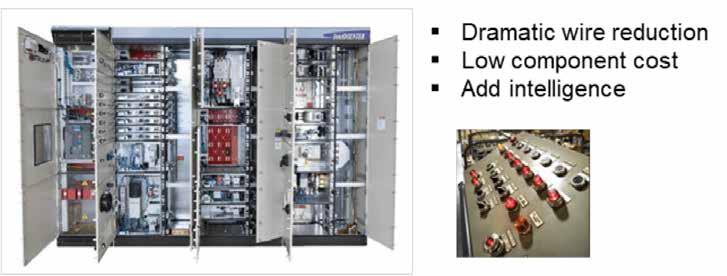
One ODVA domain-specific SPE solution is an EtherNet/IP specification for cabinets containing motor control components. This is depicted in Figure 2. The specification is included in Chapter 8-10 “Industrial EtherNet/ IP In-cabinet Bus Media and Physical Layer”.
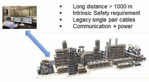
Another ODVA domain-specific SPE solution is an EtherNet/IP specification for process instruments for hazardous locations. This is depicted in Figure 3. The specification is included in Chapter 8-11 “EtherNet/IP Media and Physical Layer for Ethernet-APL (Ethernet Advanced Physical Layer)”
The EtherNet/IP Physical Layer Special Interest Group is developing EtherNet/IP Specification Enhancements (ESEs) for General Purpose SPE (GPSPE). One reason to call it “general purpose” is the intent of GPSPE to reference emerging standards, including IEEE Std 802.3-2022 (as amended by IEEE Std 802.3cg-2019), ISO/IEC 11801-3 AM1, ANSI/
TIA 568.7A, and IEC 63171 - rather than invent new technology. The current effort is to reference 10BASE-T1L.
One intent of GPSPE is to extend the SPE application space of EtherNet/IP for constrained devices across industrial domains (discrete, hybrid, and process automation) –reducing the end-device electronics and field cabling.
One GPSPE use case is to reach out from the control cabinet and into non-hazardous field locations. This is depicted in Figure 4 for discrete automation. Note that Ethernet-APL can reach out from a cabinet and into the field – for hazardous locations.
Since GPSPE is an on-going effort, many decisions have not been made or are subject to change.
EtherNet/IP for constrained devices includes both:
Reduced physical layer
• Reduced Cabling
• Connectors
• Coupling circuit
• EMC protection
• SPI MAC/PHY interface
Reduced protocol stack
• Less FLASH and RAM for smaller MCUs
• Transport (UDP-only)
• Security (DTLS-only)
GPSPE specifies a reduced physical layer. Devices can also implement the reduced protocol stack.

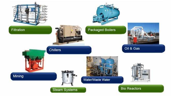
Non-hazardous instrument applications include many Process Skids (e.g., as shown in Figure 5). These skids are often specialty OEM modules that are shipped and placed at an end site. The skids may be interconnected via piping and supervisory communication to perform a series of production functions. The distances are short. These OEM applications are cost sensitive.
Other non-hazardous instrument applications are included in the plantwide automation for Life Sciences, Food and Beverage, and Water and Wastewater industries, as depicted in Figure 6 These industries may utilize skids as elements a larger plant. The distances are larger than on skids, but smaller than with large plants like in Oil and Gas.
The introduction of SPE (Ethernet-APL) is driving all instruments toward Ethernet connection in hazardous areas. Harmonization on a full suite (see Figure 7) of EtherNet/IP instruments has numerous advantages:
• Fast updates
• Reduction of gateways
• Reduction of cabling – single pair with power
• Increased information capability from some instruments
• Ability to have multiple measurements from the same instrument.
Non-hazardous locations do not yet have a full suite of SPE-based EtherNet/ IP instruments. A limited set of EtherNet/ IP instruments is sometimes utilized. These instruments are typically supplemented with HART instruments when no equivalent

EtherNet/IP instrument is available.
GPSPE could drive all instrument types toward Ethernet connection within non-hazardous areas.
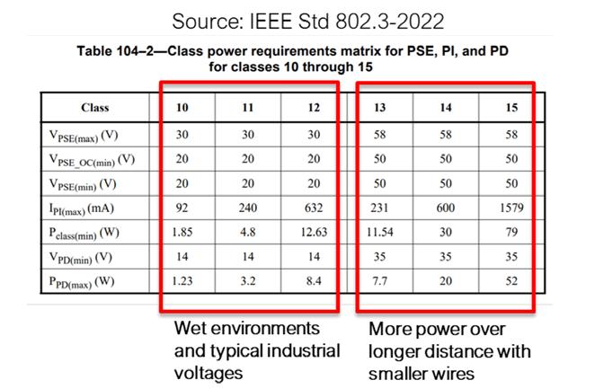
GPSPE will reference IEEE Std 802.3-2022 Clause 104 (PoDL) for power options. The PSE and PD are Type E, allowing longer distances. Classes 10-15 will be used (see Figure 8). These were added within IEEE for long reach (1000 m) and industrial usage. Classes 0-9 exist primarily for short reach (15 m) and automotive usage.
Both Plug and Play and Engineered power are being considered.
GPSPE shares basic Ethernet technology with Ethernet-APL, but each has optimizations for different industry segments. Table 1 compares multiple aspects of GPSPE and Ethernet-APL. Both support EtherNet/IP communication
over 10BASE-T1L. Differences primarily relate to the Ethernet-APL requirement to operate in hazardous locations. This leads to intrinsic safety requirements, which lead to a custom engineered power solution.
Safety Comparison of GPSPE with Ethernet-APL
Ethernet-APL devices and switches are specified for hazardous locations as found in Oil and Gas, and Chemical industries. The inclusion of intrinsic safety in Ethernet-APL devices requires a level of redundant hardware for protection against faults that can cause hazardous conditions. The amount of hardware increases with higher power levels. Switches supply power for multiple devices and have larger overhead.
GPSPE will be specified for non-hazardous locations. This reduces the redundant hardware and eliminates a major certification process. As a result, the GPSPE field device and switches are expected to be more cost efficient than the Ethernet-APL field devices
and switches.
Ethernet-APL power and voltage are quite limited due the intrinsic safety requirements. Power Class A (Ex ia IIC) provides 0.5 W @ 15 V to a device. Power Class C provides 1 W @ 15 V to a device, but only for less hazardous environments (Ex ic IIC).
While these power levels are sufficient for most of the sensor instruments in the field, there are still specific instruments, such as flow meters, that benefit from more power and therefore require secondary power supply. The secondary source would itself need to be compatible with the hazardous location. This could mean a second identical cable run (also

low wattage) that might be run for 200 m. As an alternative, the power cable may be run in an expensive explosion-proof conduit and extra measures taken in the device. Already Ethernet-APL is a large step up from 4-20 mA or HART, but the power budget is still below the optimal level.
On the other hand, GPSPE does not have these power restrictions, as no intrinsic safety requirements needs to be fulfilled. To power typical process sensors known in the non-hazardous industries, an 8 W power budget is desirable. In most cases this is sufficient even for demanding flow sensors.
GPSPE is expected to specify PoDL (Power over Data Line) Classes 10,11 and 12. An SPE switch implementing the PSE (Power Supply Equipment) function would source 30 Vdc and deliver up to 8.4 W to a PD (Powered Device). The switch itself may operate from and distribute power from a higher powered GPSPE link or from separate power.
While the ODVA GPSPE specification is still in development, the specification for EtherNet/IP for Ethernet-APL has already been published.
Vendors are currently preparing Ethernet-APL Field Devices (and switches) for the market.
There are advantages in enabling these Ethernet-APL devices to be able to attach to GPSPE:
• Hardware platform and firmware re-use
• Faster launch of GPSPE
Other devices might be specifically optimized (i.e., without Intrinsic Safety or utilizing more power) for GPSPE.
Ethernet-APL and GPSPE devices are potentially interoperable via switching (both are EtherNet/IP over 10BASE-T1L). However, the power systems are different (see Table 1). Subsequent sections discuss the differences.
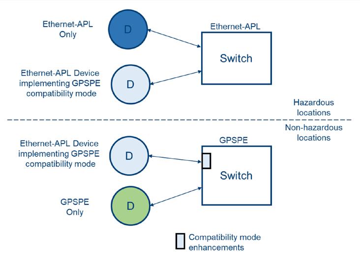
Figure 8 illustrates the concept of an optional “compatibility mode” between Ethernet-APL and GPSPE. An Ethernet-APL device that supports compatibility mode could operate with either switch.
Compatibility mode has the following attributes for Ethernet-APL field devices:
• Device is able to operate at a higher GPSPE voltage level
• Device is not damaged by the increased voltage
• Device follows GPSPE connector scheme
• Device labelled properly for non-IS locations
Compatibility mode has the following attributes for GPSPE switches:
• Can be configured to apply power directly to Ethernet-APL field devices
The GPSPE PSE would normally interact with the PD and not turn on full voltage unless a PD is present on the link. Various interaction methods are possible. The first method is Detection. A low voltage signal is placed on the link by the PSE and a PD will draw a specified current if present. The PSE must be pre- configured to supply a specific voltage and power (i.e., it is set to a specific Class). A second method is Classification, where information is exchanged between PSE and PD. This also allows PD detection – as well as the establishment of the Class without pre-configuration.
Unfortunately, unmodified Ethernet-APL devices do not support Detection or Classification. The Ethernet- APL Source (power supply to a link) is directly enabled to the Ethernet-APL Load (powered device on a link) – regardless of whether a device is present. The circuitry for PoDL was never
Physical Layer for EtherNet/IP
10BASE-T1L (initial PHY)
Non-hazardous locations
No extra IS hardware
Plus-and-play power (device detection, voltage/power negotiation)
Engineered power option
60 Vdc tolerance (from 10BASE-T1L)
Classes 10-12, 30 Vdc, up to 8.4 W
Classes 13-15, 30 Vdc, up to 52 W
Connectors and bulkheads
No IS certification or marking
specified for intrinsic safety. Additionally, the PoDL circuitry would potentially cut into the limited Ethernet-APL power budget.
One simple method for powering Ethernet-APL devices in a GPSPE system is known as PoDL-bypass. The PSE is pre-configured to provide a full voltage to the link without Detection or Classification.
The PSE Source utilizes PoDL coupling circuit and a subset of the state machines.
PoDL-bypass considerationsdamage
The pre-configured voltage in PoDL-bypass could be specified as 30 Vdc (Class 10-12) and/or 58 Vdc (Class 13-15). It is important to prevent damage.
GPSPE is expected to support both PoDL voltages and to retain the IEEE requirement for 10BASE-T1L is to tolerate up to 60 Vdc. GPSPE devices could never be damaged by direct application of 58 Vdc.
Ethernet-APL devices are not required to tolerate 60 Vdc. Ethernet-APL Field Switches Classes A and C only supply 15 Vdc to the Field Devices. This voltage and the matching current fit under the ignition curves (limits to not ignite an explosive atmosphere) and were found as optimal in power delivery. Some vendors have mentioned implementing non-replaceable fusing that would open before even reaching 30 Vdc. Other vendors may not have the fuse problem.
PoDL-bypass considerations –voltage selection
It is proposed that GPSPE only specify a PoDL-bypass option for Classes 10, 11 and 12
Physical Layer for EtherNet/IP
10BASE-T1L
Hazardous locations
Extra hardware for IS protection
Engineered power (directly applied)
60 Vdc requirement precluded, must operate up to 15 Vdc
9-15 Vdc, 0.5 W or 1 W
Terminal blocks and cable glands
IS certification and marking
(30 Vdc). An Ethernet-APL device could be powered in a GPSPE system - if it operates from and tolerates 30 Vdc. Limiting the pre-configuration voltage to 30 Vdc and designing the Ethernet-APL device to operate from and tolerate this voltage would preclude damage.
Pre-configuration of 58 Vdc may not have an advantage. 8 W is considered adequate. The non- hazardous applications do not require 1000 m distances. Likely 200 m is adequate. Class 12 voltage drop across a 200 m cable must meet the 9.5 Ω loop resistance. For a 400 m loop, we have 0.024 Ω/m (i.e.,18 AWG wires).
Design for operation/tolerance is considered more difficult. The component ratings are higher in comparison to the 15 Vdc usage, sizes are larger, and heat dissipation is likely a concern.
Additional qualification and installation restrictions may also apply when exceeding 50 V due to potential shock hazard. This is especially true for wet installations.
PoDL-bypass considerations –misapplication
A related issue concerns moving an Ethernet-APL instrument between hazardous and non-hazardous locations. When the device is placed in the non-hazardous location, there is no guarantee the device will not sustain hidden faults. When placed back in a hazardous environment, the device may not perform as intended.
It is required that for Ethernet-APL devices to be used with GPSPE, the devices are packaged and labelled without hazardous area approval
markings. It is also proposed that GPSPE avoid re-use of the Ethernet-APL specified M8 and M12 connectors. These measures reduce the possibility of misapplication and still allow the bulk of the hardware and firmware to be re-used.
GPSPE continues the trend of using SPE to displace fieldbus, sensor and device networks and to enable networking of hardwired devices and devices from point-point links. Non-hazardous process applications are prevalent.
A complete portfolio of EtherNet/IP instruments is desirable for:
• Hazardous locations (Ethernet-APL)
• Non-hazardous locations (GPSPE)
GPSPE is anticipated to bring advantages to Process Instruments in non-hazardous locations:
• Reduced wiring
• Lower cost by eliminating Intrinsic Safety
• Significant power
While there is advantage in allowing Ethernet-APL instruments to be interoperable with GPSPE, they must be designed appropriately.
David D. Brandt, Engineering Fellow, Rockwell Automation, Inc. and Michael Bückel, Head of Department | MTMP Platforms, Endress+Hauser Flowtec AG. Visit Website
Industry experts agree that the foundation of Industrial Ethernet solutions for factory automation remains laser-focused on smart connected machines, edge and cloud-based computing, the potential impact of AI technology and new products and tools that simplify the ongoing quest for IT-OT integration.

INDUSTRIAL ETHERNET FACTORY CONNECTIVITY solutions represent critical, foundational technology that provide a communications backbone for smart connected machines, improved convergence of IT-OT functions, cybersecurity and new capabilities based on industrial edge and cloud-based architectures.
For this Industrial Ethernet Connectivity update, the Industrial Ethernet Book reached out to industry experts to gain their perspectives on how technology is continuing to move ahead with a range of effective innovations targeting factory automation.
Focus on real-time capabilities
Deterministic data transmission that is crucial for time-critical applications.
Jens Geider, Portfolio Owner SCALANCE and Wolfgang Schwering, Portfolio Manager Industrial Networks, at Siemens provided input on how Industrial Ethernet connectivity is evolving to provide greater levels of performance.
Geider and Schwering told IEB that "Industrial Ethernet connectivity is advancing rapidly, driven by the need for higher performance, reliability, and real-time capabilities in industrial environments. Innovations such as Time-Sensitive Networking (TSN) are at the forefront, offering deterministic data transmission that is crucial for time-critical applications. This is achieved through standardized mechanisms for scheduling and traffic shaping, ensuring that
high-priority traffic reaches its destination within a guaranteed time frame.”
Additionally, the adoption of higher bandwidth capacities, reaching 10 Gbps and beyond, is accommodating the demand for increasing data volumes. Ethernet-based protocols are also evolving to become more robust and secure; incorporating advanced encryption and authentication methods to protect against cyber threats, ensuring that connectivity solutions not only meet the current demands for speed and efficiency but also anticipate trends towards virtualization, high-level security, and availability. To achieve the target level of availability, Parallel Redundancy Protocol (PRP) and High-availability Seamless Redundancy (HSR)
are making their way into industrial ethernet networks. These will need to operate in conjunction with proven technologies such as the Media Redundancy Protocol (MRP).
In the realm of Industrial Ethernet products, Geider and Schwering said that key technology trends are focusing on enhancing interoperability, security, and sustainability. One significant trend is the convergence of IT (Information Technology) and OT (Operational Technology) networks, facilitated by advanced Ethernet protocols that ensure seamless data exchange and communication across diverse systems and platforms. This convergence is supported by features like edge computing capabilities, where data processing occurs closer to the source of data generation, leading to reduced latency and more efficient decision-making processes.
Furthermore, there is a strong emphasis on cybersecurity features, with developments in intrusion detection systems, secure boot processes, and end-to-end encryption to safeguard industrial networks against growing cyber threats. Energy efficiency is also a focal point, with innovations aimed at reducing the power consumption of network devices, contributing to more sustainable industrial operations.
They said that the latest Industrial Ethernet
products are also bringing a host of technical benefits to the table, encompassing both hardware and software advancements. On the hardware front, there's a push towards more rugged designs that can withstand the harsh industrial conditions seen in the proliferation of industrial communication, including extreme temperatures, vibrations, and electromagnetic interference. These devices often feature advanced diagnostics and redundancy capabilities, enhancing network reliability and uptime. From a software perspective, a major benefit is the integration of sophisticated network management and monitoring tools. These tools provide real-time visibility into network performance, facilitating proactive maintenance and troubleshooting.
“Bridging these two worlds, the Industrial Edge brings capabilities directly into the network, offering options for dedicated apps to run directly where they are needed. Together, these hardware and software enhancements contribute to more resilient, adaptable, and efficient industrial networks providing higher performance and data throughput while still being easily manageable,” Geider and Schwering said.
The innovations in Industrial Ethernet are specifically designed to tackle a variety of
engineering challenges and pain points faced by customers in industrial settings. One major challenge is the need for real-time data transmission in automation and control systems, where any delay can lead to significant operational complications or worse, safety risks.
Geider and Schwering said that the introduction of deterministic networking through TSN technology addresses this by ensuring timely and predictable data delivery. Another pain point is the complexity and cost of integrating and managing disparate systems and technologies within an industrial plant. New Ethernet products are designed with improved interoperability and ease integration, reducing the engineering effort and cost associated with establishing and maintaining industrial networks.
Additionally, the growing threat of cyberattacks on industrial systems is a critical concern; thus, enhanced security features are being incorporated to protect sensitive data and ensure the integrity of industrial processes. Finally, the demand for scalable and flexible networking solutions that can adapt to changing operational needs and future expansions is being met with modular and intent based networking approaches, providing a future-proof investment for customers.
The EISW switch series provides the performance you need to expand Ethernet networks even in the most demanding environments.
• Plug-and-play simplicity
• 10/100 Mbps performance
• Supports Auto-Negotiation and Auto-MDIX
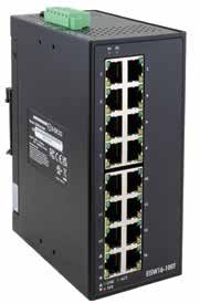


• Metal enclosure with DIN-rail or wall mounting
• Wide operating temperature range of − 40°C to +75°C
• UL/cUL Listed, CE/UKCA Mark and TAA Compliant
5 Year Warranty

Intelligence at the edge has become a standard practice.
According to Joel Albert, Vice President –Technical Services at Industrial Networking Solutions, “we are finally seeing fully managed networks with intelligence at the edge as standard practice. I can’t remember the last time we delivered an unmanaged switch with our services team. Most customers expect a properly segmented network, well defined IP schema, managed routes/ACLs, edge compute, OT network DMZs, and proper cabling standards. With these attributes in place for an OT network, customers are seeing more stability, expandability, security, information, and much better bandwidth performance. As a funny anecdote, I mentioned to one of our customers that their updated network reduced their transmitted data about 80%. His eyes opened wide, and he said, ‘No, I now have 80% more bandwidth for more data.’ It was a cool moment.”
Albert said that key Industrial Ethernet technology trends, and new networking software technologies are the focus of ongoing development of advanced networking solutions for factory automation applications.
“We are happy to see customers moving to MQTT and away from legacy polling protocols. The very nature of MQTT requires intelligence at the edge which opens a whole world of data collection possibilities,” Albert said.
“With these trends, most of our vendors are putting edge computing directly on their networking devices. We now have integrated cybersecurity, machine learning, data store-and-forward, direct integration to cloud services, and much more. So, once a customer puts in a properly managed network with intelligence at the edge, they now have a true industry 4.0 architecture, and the data model easily mirrors and supports their operations.”
As mentioned above, edge computing
with Linux operating systems allows for an Industry 4.0 model with better performance, security, data retention, dynamic data, unified UDTs, and seamless integration to cloud services.
Solutions are also being developed to deal with the engineering challenges and “pain points” that innovations are designed to address for customers.
“With modern day networking technology, it’s much easier to start with the data model and then back into the required network infrastructure,” Albert said.
“So, we’re seeing a much tighter alignment of traditional networking and software engineering. The mistakes we see are traditional SCADA engineers are not properly architecting the data model; inversely, we often see traditional network engineers not implementing a network with integrated intelligence. Software, data, and hardware are not mutually exclusive skillsets anymore.”

Ongoing push for networking innovations.
Pooyan Dehghani, Product Marketing Manager at Moxa Europe said that Industrial Ethernet connectivity plays a pivotal role in driving the transformation of industrial operations and the evolution of Industrial Ethernet encompasses the following aspects.
Higher Bandwidth: With a surge in the number of data-oriented industrial applications, the demand to support real-time control, monitoring, and data analysis arises. Industrial devices continue to advance, offering higher data speeds for system communications.
Minimal latency: Real-time communication across most industrial applications demands minimal latency. The Industrial Ethernet protocols have been developed to support low-latency communication.
Enhanced Cybersecurity Measures: Industrial Ethernet technologies are steadily moving toward greater cybersecurity aspects, with enhanced measures being implemented as
industrial systems become more interconnected.
Durability and Reliability: Manufacturers are increasingly prioritizing the durability and reliability of Industrial Ethernet equipment, with many providers focusing on creating even more ruggedized devices than those of the past.
Wireless Connectivity: While wired Ethernet is still commonly preferred for its reliability and performance, wireless options such as Wi-Fi, Bluetooth, and cellular are becoming more popular in situations that require mobility or flexibility.
Technology trends lead the way Dehghani said that key technology trends in new Industrial Ethernet products, and expanded feature sets are the focus of ongoing development efforts.
“The motivation toward Industry 4.0 is driven by increasing global competition, rapid technological advancement, demand for customization, reduced product delivery time, operational efficiency, and reliability. Achieving these goals is possible through digital transformation and automation trends,”
Dehghani said.
“Not surprisingly, many technology trends in Industrial Ethernet products align with the goals of Industry 4.0. Goals such as providing faster communication, reducing latency, increasing interoperability of devices, and enhancing cybersecurity.”
Dehghani cited the following areas as the focus of ongoing development of new Industrial Ethernet connectivity solutions.
Higher Data Transmission Rates with low latency: The increasing requirements for transferring large volumes of data push Industrial Ethernet products to increase their data transmission rates. This trend involves adopting technologies such as Gigabit Ethernet, 10 Gigabit Ethernet, and even higher speeds in some cases.
Emerging industrial technologies focus on enhancing data transmission speeds and reducing latency by leveraging new Ethernet hardware, protocols, and network architecture. For example, Quality of Service (QoS) is one such technology that optimizes network performance by prioritizing critical data packets according
to predefined parameters. This ensures optimal performance and responsiveness of applications and services.
5G and 6G Connectivity: The rollout of 5G networks and emerging of 6G connectivity is transforming industrial communications. 5G and emerging 6G connectivity offer higher bandwidth frequencies over larger distances and reduced latency, resulting in a more reliable network. Applications that exist in 4G will become 10 times faster in 5G and 100 times faster in 6G. Remote monitoring, autonomous mobile robots, and real-time tracking materials in logistic applications are some of the uses of these new technologies.
Ethernet APL and SPE: Ethernet APL (Advanced Physical Layer) and SPE (Single Pair Ethernet) are emerging Ethernet technologies designed for industrial networking applications. These technologies support high-speed data transfer over large distances. Ethernet APL is specifically developed for process automation applications in hazardous locations in which standard Ethernet solutions cannot be used. On the other hand, SPE employs a single twisted
pair of cables to reduce cabling complexity and cost compared to traditional Ethernet solutions.
Security Enhancements: Industrial networks are increasingly targeted by cyber threats, so ongoing development in Industrial Ethernet products includes robust security features. NIS2 (Network and Information Security Directive 2) as a European directive and IEC 62443 are two significant standards and directives aimed at enhancing cybersecurity, particularly in industrial and critical infrastructure sectors.
Various concepts and technologies, such as Zero Trust Architecture (ZTA), Network Segmentation using virtual LANs (VLANs) and firewalls, Network Traffic Analysis (NTA) solutions, and Access Management solutions, contribute to enhancing cybersecurity in industrial environments.
In addition to cybersecurity threats, reliability, and resilience in industrial environments, which have already been discussed, Industrial Ethernet products are designed to address several other engineering challenges and pain points that
customers commonly encounter in industrial automation and control systems. Some of the challenges that Dehghani summarized include:
Legacy System Integration: Many companies still use legacy equipment that may not be compatible with ethernet-based communication protocols. New technologies aim to assist customers in seamlessly integrating their legacy systems with modern ones, avoiding the need for expensive upgrades or replacements.
Complexity and Scalability: As the number of devices in industrial applications increases, managing the network will become complicated. One of the challenges in industrial setups is to ensure the scalability of the network. This can be achieved by offering easy-to-use user interfaces, centralized network management solutions, and scalable architectures.
Return on Investment (ROI): Achieving a favorable return on investment (ROI) is a constant challenge in industrial applications. There are different ways that industrial networking devices can contribute. The extended life cycle and innovative designs of these products can help in reducing energy
consumption and maintenance costs.
Moreover, the reduction of unscheduled downtime can significantly reduce production losses and operational interruptions.
Knowledge gap of users and decision-makers: One of the unique engineering challenges in industrial networking is the knowledge gap among users and decision-makers. This knowledge gap can impact the design, implementation, and maintenance of networks. Challenges include the complexity of industrial systems due to a variety of components and protocols, ensuring compatibility of legacy systems with modern networking standards, cybersecurity awareness, scalability, and future-proofing networks according to evolving technologies. Troubleshooting network issues is also a significant challenge. Addressing these challenges requires investment in the training and professional development of individuals working in this field.
Evolving to provide higher levels of performance, diagnostics and network monitoring.
According to Mike Willett, Network Engineer at Red Lion Controls, not only is Industrial Ethernet connectivity evolving to provide greater levels of performance, but it is also evolving to provide greater levels of diagnostic and passive monitoring which maximizes usability.
“We have tools to show visibility into our networks to make sure that we are maintaining a high level of performance,” Willett told IEB recently. “We also have advancements to remote access that is secure but also more intuitive for Industrial Ethernet users to deploy and benefit from. The aggregation of tools like these is what drives the evolution of performance within industrial networks. Also, network switches are evolving.”
The NT5000 switches from Red Lion are all gigabit to enforce faster bandwidth. Utilizing the industrial redundancy protocol, N-Ring creates an extremely fast redundant network which is very simple to configure. N-Ring only needs to be configured on one switch to make that switch the N-Ring manager then all the other switches in the ring will function as N-Ring Auto Members with no additional configuration steps.
“This is great especially in networks that have a large number of switches. The ease of use of this protocol and others contributes to a greater level of performance. Also, The NT5000 switches have a very fast bootup time which helps to limit downtime. This also contributes to a greater level of performance. So, overall, there are many contributing factors to provide greater
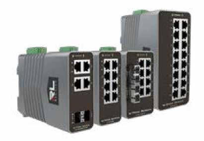
levels of performance in Industrial Ethernet connectivity,” Willett said.
Willett added that some key technology trends in Industrial Ethernet products currently are security focused. Maintaining a level of security to employ restrictions on user access with a feature like RADIUS with 802.1X. Also, restricting devices with features like Port Security and Access Lists.
“Adding segmentation to your network using VLANs is an essential tool. We are seeing more and more of a need for advanced IT type of security within Industrial Ethernet. So, to have a device that can support these advanced features but also be intuitive for Industrial Ethernet users to deploy is helping to move this trend further. The NT5000 switch series from Red Lion was designed with this exact concept in mind. It has a full feature set to develop and maintain an Industrial Ethernet network but also the ease-of-use factor when configuring these switches is essential,” Willett said.
Willett added that the key technical benefits from a software perspective would be things like having a full feature set of advanced managed features but also creating a technical advantage with the ease-of-use factor of those features. This will also enable Industrial Ethernet users to have more control over the configuration of the network and, utilizing additional software tools to monitor diagnostics, to provide greater visibility into the data flow of the network.
The N-View 2 platform from Red Lion is a tool to show status and port diagnostics from N-Tron Series switches. It is a tool that can be used during troubleshooting to diagnose potential network issues related to things like faulty cables, noise issues and
other things.
“Another great visual feature of the Red Lion NT5000 switches is that they have a relay contact on the power terminal that can be used for alarming based on certain configuration parameters such as a redundancy ring break, power fault and other things,’ Willett said. “For example, a user could connect a light to this alarm contact to show a visual alarm when it is triggered. This would be useful in a manufacturing network to show a visual fault on the plant floor and also in many other examples. Ease of use and passive monitoring are great ways to enhance the efficiency of the industrial network while giving the users valuable insight into the network performance.”
Willett said that deploying a device that is intuitive while maintaining the ease of use factor within its management absolutely provides relief to various engineering challenges and pain points.
As a user of an industrial network, deploying and maintaining a network device that accomplishes this can be a great advantage. This can empower the industrial network user to build out an efficient network and be confident with the setup. This can also save time and resources since involving the corporate IT network users will become less necessary.
The NT5000 switches from Red Lion are designed specifically for this use case. They can cater to both the IT network user as well as the industrial network user. But, they certainly provide a great advantage for the industrial network user. The modern visuals, the alarming capabilities, and the overall ease of use make this switch platform significant for alleviating a lot of the challenges and pain points that a user can be faced with.
Al Presher, Editor, Industrial Ethernet BookNew machine concept for the industrial production of brooms and brushes uses distributed servo drive technology and EtherCAT P to facilitate a production process overhaul.
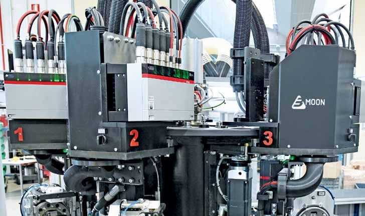
INDUSTRIAL PRODUCTION OF BROOMS AND brushes is not much different from the classic manual approach; the machines just work faster – but still not fast enough for Italian machine builder Borghi S.p.A. This is where the Moon project came in, allowing the company to make a significant leap in terms of productivity.
The project saw the development and implementation of a completely new production sequence using PC-based control and the AMP8000 distributed servo drive system based on EtherCAT P.
At first glance, they are just everyday objects – brooms and brushes in a wide variety of shapes, materials, and colors for both domestic and industrial use.
The range of materials and dimensions is just as broad, spanning from small brushes made of steel, polypropylene, horsehair, or Tampico fiber through to large rollers for street cleaning vehicles. Therefore,
state-of-the-art production technology is required to manufacture brooms, brushes, and mops the way Borghi does: economically, in high volumes, and with precision and quality.
Based in the Italian town of Castelfranco Emilia, Modena, Borghi’s roots date back to 1948, giving the company close to 75 years of expertise in this specific segment. Today, Borghi produces in several subsidiaries, including those in Brazil, China, India, Poland, and Spain. It also has sales offices in a number of strategically important regions, such as Asia, Europe, and the USA.
“Borghi is now an international group,” explains Chairman Paolo Roversi, “where more than 250 employees are involved not only in the production of machines, but also in the assembly of control cabinets, mold making, and much more besides. You will often find the work of one of our machines behind the products marketed by a host of
major brush and broom brands,” he goes on to point out.
Broom production with stringent requirements
When it comes to manufacturing a broom, the brush is the most important element. Brushes consist of several rows of fibers that are threaded into what is known as a ‘lath’. Not only can these have completely different geometries, but they can also be made of different materials. “For example, the ability to process synthetic, natural, and metallic fibers all in a single plant calls for extremely high flexibility,” notes Paolo Roversi.
The classic cycle of brush production starts with feeding in the base plates, which are sent to the drilling station once inserted. In the next phase, the tufts are inserted into the drilled plates before being cut to size. The final step is for the finished product to be set aside. This last machining step almost always coincides with the insertion of the next base
plate ready for a new cycle to begin. “During the transition between the various processing steps, the motion axes of the work stations constantly have to stop briefly and allow the semi-finished product to pass to the next station,” explains Paolo Roversi, pointing out a major productivity bottleneck. This brief stop typically lasts for 2 to 3 seconds, which might not sound like much, but still represents a productivity loss of around 20 percent for a complete cycle of about 15 seconds. At the same time, these forced breaks hold enormous potential for productivity gains.
Pause times eliminated via motion control
This is exactly where Borghi’s Moon project came into play to optimize the performance and efficiency of the machines. “With our new generation of machines, we wanted to break with the classic pattern of phase change cycles and develop a machine concept that can operate continuously,” Paolo Roversi notes, pointing out the optimized approach to brush production.
This requires a completely different machine design and an automation supplier who can handle this high level of complexity with a safe, reliable, and deterministic approach. After evaluating various automation concepts, the decision was made in favor of Beckhoff, whose automation solutions, which include the AMP8000 distributed servo drive system and EtherCAT P, made implementation of the concept possible in the first place, recalls Paolo Roversi.
The mechanics had to be extensively redeveloped to enable continuous operation of the machine, with the core element comprising four small, independent machining turrets that transfer the plates seamlessly
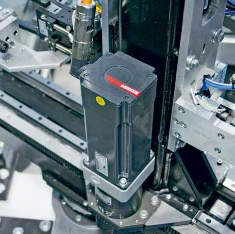
from one machining phase to the next. Each machining turret can be flexibly positioned via five servo drives to suit the formats of the plates being processed. This concept requires compact and powerful drive technology in the form of AMP8000 distributed servo drives

SOURCE: © BECKHOFF
with integrated power electronics. A single EtherCAT P line is used to connect power and communication, including safety, which not only saves space on the turrets, but also cuts down weight.
Optimized space requirements in the machine and control cabinet
The AMP8600 supply module plays a key role in the distributed power supply: one IP65-protected power supply per turret is sufficient to supply its five drives with power and communication via EtherCAT P. The small footprint of the AMP8000 servo drives, the small size and flexibility of the distributed supply module, and the minimal wiring work required for EtherCAT P were essential for meeting the requirements in terms of machine compactness, performance, and reliability.
“We were never on our own when it came to implementing this innovative automation concept,” recalls Paolo Roversi, “The on-site support from the Beckhoff experts made everything easier. What’s more, the fact that we were working with a single project partner to handle all the automation elements from the control panel to the drive meant the compatibility issues that used to occur with multiple suppliers were no longer a problem.”
The consistently distributed approach, with around 50% of the power electronics located


directly on the machine, also has a positive effect on the footprint: despite having a total of 45 axes, the machine control cabinet is highly compact and offers sufficient space for the CX2040, the EtherCAT Terminals, and additional servo drives from the AX8000 series. Paolo Roversi enthuses, “This concept has resulted in significant savings in terms of cost, materials, space, and installation effort.”
Today’s machines are now all developed with Industrie 4.0 in mind as standard, complete with the corresponding connectivity and sensor technology. According to Paolo Roversi, Beckhoff has also simplified programming in this respect, with TwinCAT 3 using the standardized architecture that is new to Borghi throughout: “At the same time, there is also plenty of space left for future expansions, for developing new models, and for OT/IT integration. PC-based control from Beckhoff offers maximum scalability for this and enables simple integration of multiple controllers and the HMI in a single standard hardware.”
Dirk Hansen, Senior Product Manager Drive Technology, Beckhoff Automation.
Industrial enterprises around the world are seeking new ways to increase the resiliency and security of their OT functions. A layered security approach strengthens the security posture of the organization, protects upstream and downstream partners, and enhances the security of the industrial sector overall.
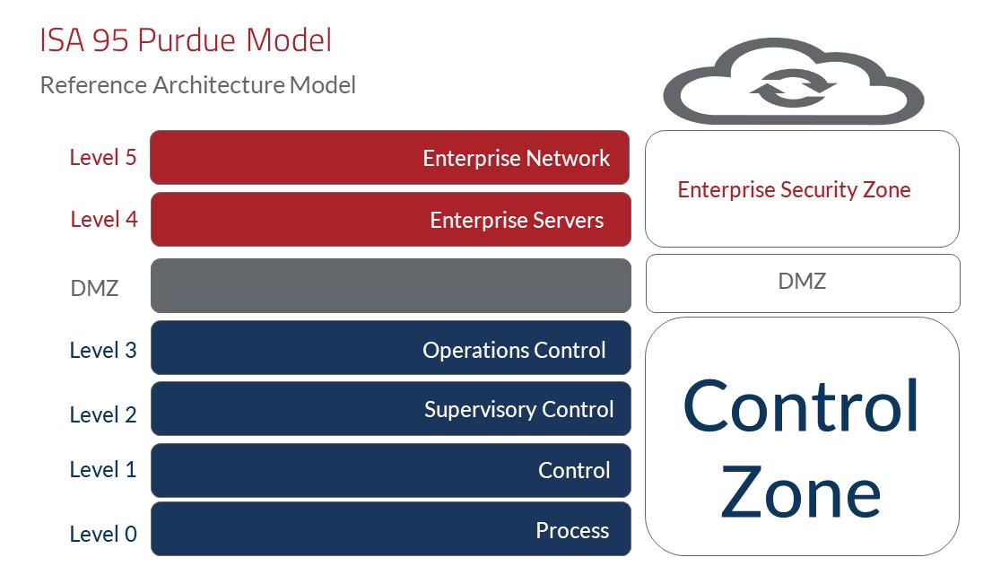
WHILE MODERN INDUSTRIAL ENTERPRISES work hard to prioritize security, the game has recently grown tougher. Industrial equipment and PLCs are now more frequent targets of cyberattacks, adding pressure and urgency to the task. At the same time, controls engineers are in the early stages of familiarizing themselves with cybersecurity risks and solutions, and how to address these quickly in the Operational Technology (OT) environment.
The good news is that as industrial automation control systems become smarter and digitized, they benefit from years of Information Technology (IT) experience in cybersecurity best practices.
The IEC 62443 standard is a consensusbased cybersecurity standard for industrial automation and control system (IACS) applications. It consolidates global IT cybersecurity best practices and translates it into security standards for industrial applications. The result is a solid roadmap for industrial enterprises and equipment owners seeking to shield data and systems from
breach or damage and to strengthen their overall security posture.
The standard defines how networks and connections should be configured and secured for the entire lifecycle of industrial applications – from design through to decommissioning. It drives a crucial point home, one learned and borrowed from IT: Security is not just implemented but needs to be continuously improved.
In industrial automation, that means adopting a layered security approach. At the level of network connectivity, the IEC 62443 standard establishes requirements for dividing systems into segments as a key security measure to fortify industrial systems.
Consider a factory automation facility with separate assembly lines (Lines A, B, C, D), each of which encompasses several processes and multiple input/output (I/O) devices, Programmable Logic Controllers (PLCs),
and Variable Frequency Drives (VFDs). Many organizations maintain flat networks with no divisions between different lines. The problem is that a device plugged in anywhere can access every other part of the system.
This ease of connectivity is a major security risk and can lead to intentional or unintentional compromise. An employee laptop infected with malware, for example, could damage the rest of the system. A hacker with malicious intent could infiltrate one network and gain easy access to the others.
A safer approach is to segment the factory floor into multiple smaller containers, called zones. Since each zone has its own network, any device plugged into that zone can only access the processes and devices in that area. Zones create a layered security boundary with process control and help maintain the same security level for all devices within that zone.
Zones aren’t isolated from one another, however. Communication between devices in different zones can be enabled through conduits that control and monitor traffic in

and out of individual segments.
For example, if our imaginary facility’s Line A had a PLC that needed to communicate to a PLC in Line C, a conduit would be set up to connect Line A to Line B, and a second conduit would connect Line B to Line C. Those conduits would block or allow traffic. Done right, they would also provide visibility into what’s happening at each boundary.
The challenge of traditional VLAN
A conventional approach to zone segmentation would use VLAN technology. For that, you need to configure multiple VLAN subnets – one for each zone – each with its own unique IP address, subnet mask, and default gateway. For devices to communicate properly within and between zones, every single device in those VLAN subnets – PLCs, VFDs, and I/O devices – would need to be updated with new parameters reflecting those new IP addresses. You’d have to set up routers for those subnets.
You’d also need firewalls to block traffic ingress and egress at transport and network layers and effectively allow or disallow communication through segment boundaries.
Getting VLAN, router, and firewall technology to work effectively together can be a challenging process. Every piece adds a layer of complexity, and a single change introduced to one part of the solution requires adjustments to every other device.
When an industrial process has been running reliably for 5 to 10 years or more, any change to that process is daunting. The concern with VLAN technology is that what begins with a little downtime could end up jeopardizing the
whole process.
Solving network segmentation using VLANs requires a significant time and labor investment. On top of the work involved, the number of configuration changes required introduces significant risk. IP addresses of hundreds or even thousands of devices may need updating. A simple typing error could bring operations to a halt and necessitate a lengthy troubleshooting process to identify the error and restore the system. Key Performance Indicators (KPIs) including Overall Equipment Effectiveness (OEE), productivity, and quality could decline during the ensuing shutdown.
While VLAN still suits many industrial contexts, industrial firewalls offer a simpler method. In this case, a firewall device is installed into the industrial control panel and serves as a conduit between two zones (e.g. Line A and Line B). With this approach, rather than having a single cable running between Lines A and B, cables from Line A and Line B both plug into the firewall in the panel. The firewall acts as the conduit and provides the necessary segmentation between zones.
Some firewall-enabled units provide firewall protection as well as traffic control and monitoring functionality. In this case, they eliminate the need for VLANs and routers, which can be beneficial for organizations seeking simplicity. In contrast to the VLAN approach, a firewall device can support zones and conduits capability and preserve network communication without requiring
SOURCE: RED LION CONTROLS
any time-consuming or risky changes to network devices. For organizations without a dedicated team of networking or IT security personnel, this solution can be advantageous. Some firewall devices do not expect or require special expertise and the installation runs through a self-guided process.
Some control panel-mounted firewall devices come with configuration software enabled designed to automatically create a host list of devices trying to communicate with it. With this auto-generated list, the user only needs to know which hosts (and which zones) should be connected to each other and which connections should be blocked. With some firewall devices, users can easily and securely view and manage those decisions using a graphical user interface.
Advanced industrial firewalls often provide a Syslog among their system controls. This feature logs and stores network events involving the device. In the case of a cyber incident or attack, those network events can be collected and used to alert the IT department that something has occurred.
Given the mounting threat of cyberattack on critical infrastructure and supply chains, industrial enterprises around the world are seeking new ways to increase the resiliency and security of their OT functions.
Experienced controls engineers sometimes feel wet behind the ears when it comes to cybersecurity. Fortunately, industrial cybersecurity standards, such as IEC 62443, have their best interests in mind: high uptime and compliance. The tools that deliver those priorities best are those that support IT cybersecurity principles by design.
When safer, stricter access control is a priority, large, flat networks are no longer viable options for automated industrial applications. A zones and conduits approach to network communication meets modern standards and provides more robust security and the necessary traffic control. Organizations have good options to choose from in both conventional VLAN and industrial firewall devices. Depending on the needs of the organization and the skillset of its operators, the latter can sometimes offer a simpler choice.
Adopting a layered security approach doesn’t just make engineers look good. It strengthens the security posture of the organization, protects upstream and downstream partners, and enhances the security of the industrial sector overall.
Barry Turner, Technical Business Development Manager, Red Lion Controls, Red Lion Controls.Learn More
Pharmaceutical production system scales up rapidly despite incompatible equipment, lockdown, logistics challenges, and remote teams. Software modules offer detailed visibility into production through seamless data exchange and will help optimize resources and plan for future demand.
DURING THE YEAR 2020, DOZENS OF COMPANIES worldwide worked to develop vaccines for the pandemic-causing virus SARS-CoV-2, known to the world as COVID-19. Four goals had to be met: vaccine efficiency, clinical trial completion, worldwide regulatory approval, and vaccine production.
Scaling up production to supply billions of doses per year would be a daunting task, and waiting for clinical trials to be completed first would take time. The one thing that the world did not have in 2020 was time.
So vaccine production needed to be started in parallel with clinical tests, with the risk that if the product was not authorized, all production would have to be dumped as unsellable.
The Galician company Biofabri, a subsidiary of Zendal, the Spanish international biopharmaceutical group, became responsible for industrial production of the antigen vaccine for most of Europe. Their task was daunting.
Zendal includes seven facilities focused on Human and Animal Health, including research, development, manufacturing, and marketing of vaccines and other biologics, pharmaceuticals, and probiotics. Based in O Porriño, in northwest Spain, the company employs over 650 professionals at five production sites across Spain and Portugal.
With more than 30 years of experience in the biopharmaceutical sector, Zendal is known for its flexibility in adapting existing installations for new animal and human vaccine products. But this flexibility would be tested beyond limits to produce the new Covid vaccine.
Zendal's challenge
Constructing and automating a new fill-andfinish facility would somehow have to be accomplished during a worldwide pandemic, in a country with one of the strictest lockdowns. From March 2020, apart from designated primary services, Spain’s population was not allowed out of their homes except for medical reasons or to buy food. For the following nine months, travel outside of their local state area without authorization was also prohibited. Logistics were soon in chaos. Orders for anything associated with sanitary or pharmaceutical use became impossible to fill as both stock and production dried up. Delivery


dates became meaningless. Sanitary certified stainless steel such as tanks, cabinets, and tubing were unavailable. Industrial supplies such as machinery, instrumentation, and valves were in short supply, and as global supply chains broke, control equipment such as PLCs, PCs, and even basic items like instrumentation wiring, cable ducting, and terminals became impossible to source.
For production control, many existing plant areas used single-loop controllers and several generations of PLCs from various suppliers. In addition, Zendal had no control over the make or model of PLCs that package suppliers would provide with new equipment. There was no time to substitute these or migrate to a centralized control system.
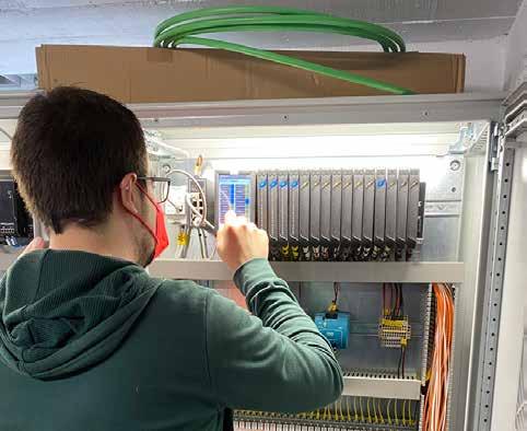
So they decided to add a new control system that could communicate with standalone equipment using nonstandard protocols, sending setpoints and control commands, reading their process inputs and outputs, and storing data in a SCADA system.
The new SCADA platform was essential to meet strict regulatory requirements. For example, the U.S. Food and Drug Administration (FDA) regulation on electronic records required that even the name of anyone who modifies a process setpoint must be traceable and explainable to FDA inspectors.
Zendal also required a flexible data
historian, integrating information not only from the SCADA and control systems, but also from many other data sources and databases.
Assuming the vaccine would pass clinical trials, centralized recording in the data historian would be vital in allowing the sale of the vaccines in production.
In addition, the new system would need to provide a common user interface to replace the incompatible individual HMIs throughout the plant and also be accessible by any authorized user on the IT network, or even off site though secure VPN connections. And perhaps most important was cybersecurity.
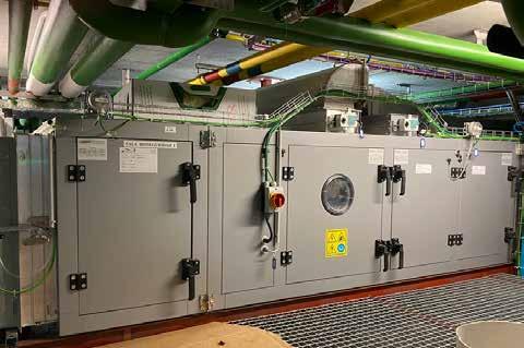
SOURCE: OPTO
Priority One: protect production control systems against cyberattack
Pharmaceutical companies involved with Covid-19 vaccine production became a target for cyberattacks. But remote connectivity to the system was required for staff working from home, for European suppliers who could not send specialists to Spain, for control system and SCADA access, and for software development by two separate teams, 575 kilometers (more than 350 miles) away.
While the advantages of connecting production networks with IT networks are indisputable, this integration also opens the possibility of organized cyberattacks, resulting in loss of production for hours, days, or weeks or even closing a company down.
At Zendal, production engineering, maintenance, and IT departments worked together to construct a more secure platform for production control based on five pillars:
• Eliminate any dependency on Microsoft Windows in the production environment. Windows attracts more interest from hackers than any other operating system and behaves badly after power outages.
• Use thin-client computers in the production process, connected to serverbased software and replaceable in less than 15 minutes. Install no additional software and do not use them for historical data storage, which would be lost in a hardware failure or an attack on the file storage system.
• Physically separate production networks (OT) from the corporate computer network (IT), using managed switches and gateways to create both vertical and horizontal network segmentation.
• Build a control system architecture that can continue without the network if a cyberattack occurs at the corporate level.
• Use only process controllers with an internal firewall to avoid cyberattacks if either IT or OT networks are compromised.
SOURCE:
With all these challenges—pandemic limitations, system integration with old and new equipment (especially specialized equipment lacking current security and communication technology), SCADA and HMI requirements, more than 20 suppliers, and cybersecurity demands—Zendal knew they needed to work with a versatile, quick, and flexible technology integrator.
They found the perfect partner in Optomation Systems, based in Madrid. With extensive control experience for other pharmaceutical companies, they are well known for their flexibility. Optomation took a close look at the requirements and recommended the Opto 22 groov EPIC system and Inductive Automation’s Ignition SCADA. Opto 22’s official representative for Spain and Portugal
since 1997, Optomation is also a certified Gold Level Integrator for Inductive Automation.
To meet committed start-up dates, Zendal formed a single integrated team that would meet only virtually. The team consisted of key staff from their own Engineering, Maintenance, and IT departments, and key staff from Optomation.
System hardware was installed, wired, and checked in suppliers’ workshops before being transported to the site where it was installed and connected to the company’s network, allowing specialist engineers to connect all the way from Madrid.
As Covid-19 continued to spread, key workers became infected and unavailable to work. It was the perfect storm of challenges for supplying a high-profile industrial automation project. For those involved, it would be the most difficult automation project of their careers.
The choice: groov EPIC and Ignition
Opto 22 hardware and software are developed and manufactured by Opto 22 in Temecula, California, in the U.S. The company’s flagship product groov EPIC combines an advanced
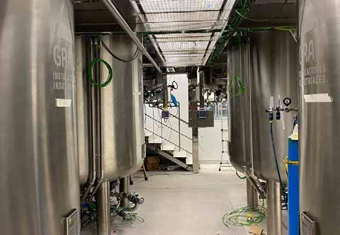
hardware platform, lifetime warranty on most I/O, security features, and embedded application software to handle any modern industrial automation or IIoT project.
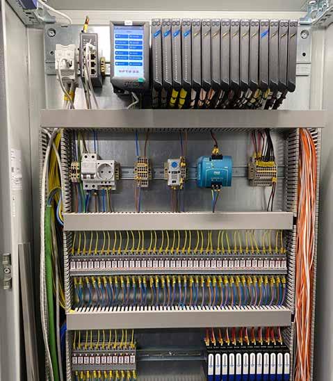
SOURCE: OPTO 22
The groov EPIC hardware price includes access to software with no hidden surcharges like number of tags, size of database, number of devices used, or annual license fees.
Opto 22 provides all software updates as new firmware without charge. Two main alternatives are included for programming real-time control applications: its own PAC Control and CODESYS, the IEC 61131-3 programming tool for more PLC-oriented applications.
Another reason for choosing Opto 22: the company was one of the few control suppliers still able to ship product during the pandemic. In its nearly 50 years of history, Opto 22 has never subcontracted production overseas to reduce costs. They continue to design, manufacture, and distribute from their factory headquarters in the U.S.
Due to the pandemic, Zendal was classified as a priority one customer, and batch shipments of required hardware were airfreighted to Spain in less than two weeks from order entry.
For Zendal, groov EPIC processors were supplied with 16-module chassis racks, allowing expansion up to 384 hardwired I/O, unlimited remote I/O, and data from externally connected PLCs or other intelligent devices. All processors can share data using peerto-peer communication over the Ethernet network.
Ignition software is developed and marketed by Inductive Automation in Folsom, California, in the U.S. It is regarded as the most complete and advanced distributed SCADA software in the market, used by over half of America’s Fortune 100 companies, in distributed manufacturing, industrial automation, process control, utilities, and transport infrastructures. Unlike competitors’ products, Ignition can
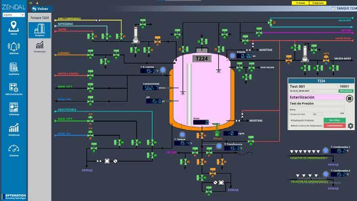
be scaled up without additional charges. The software runs on various operating systems and hardware platforms and includes drivers to connect virtually any industrial hardware or software. The company does not charge for connecting additional devices or tags to the servers.
Similarly, Ignition’s Visualization HMI module has no charge for added users. Zendal currently has between 30 and 60 clients connected simultaneously to the system, which in time will probably increase to over 150 simultaneous users.
Opto 22 provides both Ignition EDGE and Ignition Standard software products embedded in groov EPIC controller firmware for optional activation and licensing. Network problems are avoided because the SCADA data collector is fully integrated in the same controller hardware, simplifying communication and creating a secure connection between them in a single hybrid system. For the pharmaceutical industry, the importance of this combined solution cannot be overestimated.
When Optomation and Zendal chose Opto 22 and Inductive Automation for the system, they knew that the hybrid solution and guarantees offered by groov EPIC and Ignition ticked all the boxes they needed:
• Security
• Network efficiency
• Ease of upgrading
• Rapid system growth
• Remote development and testing
The groov EPIC process controllers use a crypto-signed industrial runtime version of Linux, supplied and maintained by Opto 22. A crypto-signed operating system cannot be modified or substituted by a third party, eliminating the possibility of obtaining system access through contaminated updates or patches.
Traditionally, integrating any process control system with a SCADA product requires protecting not only both systems, but also the network connections between them. But because groov EPIC runs control software and SCADA software in the same hardware platform, communication between them is internal and protection is built in. Both Opto 22 and Inductive Automation promptly address vulnerabilities, and Opto 22 provides a free groov EPIC firmware revision to resolve them.
Communication between any client and the groov EPIC server requires only a web browser on the client and is encrypted using a secure channel to protect sensitive transaction data. groov EPIC’s configurable internal firewall defines which applications can be externally accessed and which network hardware interface each application uses.
In typical SCADA architectures, the system constantly scans PLCs and control equipment for data, creating unnecessary traffic. Any network problem results in data loss.
For Zendal, the Ignition EDGE software in the groov EPIC processor remotely collects real-time industrial data from the controller, data marked for historical storage, operator actions, and process alarm data. The software then uses secure protocols and reporting by exception to send the data to real-time relational databases. Without scanning and unnecessarily repetitive data, network traffic is reduced to a minimum.
If a network problem occurs, all data is automatically buffered in the Ignition EDGE gateway for up to seven days or 1,000,000 data samples. Once normal network communications are restored, this buffered data is transferred and merged into the centralized Ignition database.
A corporate-level cyberattack could compromise communication with the centralized SCADA system. Zendal provides plant operators a local user interface through the optional EDGE Panel in production-area groov EPICs, so that a client computer can still connect locally for control and regulatory data.
“In the pharmaceutical industry, losing historical data is not an option, as without access to batch manufacturing data, the product is unsellable,” notes George Mitchell of Optomation. “The full value of Ignition EDGE in groov EPIC only becomes apparent when you have network problems.”
Scaling up: planning for system growth of 2000% in three years
The initial scope at Zendal was to monitor and register working temperatures and alarms
for 15 deep-storage freezers, where the early COVID-19 virus samples were stored at -80 °C. (-112 °F).
But Zendal knew they were not looking simply for a precision controller for batch recording and data logging. Instead, they needed a flexible control system that would cover all the company’s future requirements, not only for this installation, but for all the other production facilities on the same site, other production centers across Spain, and a new production center being built in Portugal.
“We knew this baby would grow, but we honestly had no idea how big it would get,” says David Vila, responsible for Installations in Zendal.
“We just knew we needed something that would have the capacity to scale up at the same speed as our business and would not need to be replaced with something bigger or better in a few years. We do not have the time or resources to start again from zero.”
So Zendal initially chose a single groov EPIC controller and chassis, with two 8-channel GRV-AIRTD analog input modules and an onboard Ignition Standard license.
The processor and its I/O met harsh industrial conditions and modern cybersecurity standards; the Ignition software complied with GMP and FDA guidelines for use in pharmaceutical installations, especially with respect to electronic records and electronic signatures.
A NAS drive was added to the controller to support Ignition’s Tag Historian module, and

the VISION module with a single user license allowed the temperatures to be monitored from anywhere on the IT network.
Three years later, 19 groov EPIC controllers are on site, each covering a distributed production area or process. Zendal continues to use the same Ignition Standard Gateway license purchased with the first controller. At the time of writing, the gateway receives and manages data from 28,6000 OPC UA tags
and a total of 186,900 atomic or derived tags, used to display, control, and store data for regulatory requirements from the entire company’s production systems, all without any additional surcharges for system expansion.
In 2022, Zendal inaugurated a new production facility in Portugal. They installed a new redundant Ignition Standard Server locally to handle the complete SCADA requirements of the production facility, communicate to
multiple control packages (some based on Siemens and Allen Bradley PLCs in addition to groov EPIC controllers), and provide a user interface and a tag historian package for the local plant.
The sites in Portugal and Spain are interconnected through secure VPN connections, and authorized users connected to the Ignition servers in Spain can switch to the Ignition servers in Portugal for a real-time connection to processes running in another country. The Ignition distributed architecture model provides this functionality without any extra programming or costs.
Each new groov EPIC controller added to a production facility adds another distributed co-processor to Ignition’s total computing power. Ignition EDGE gateways running on the groov EPIC controllers scan and update all data in real time, performing local processing at the edge of the network before transferring postprocessed data to the centralized Standard Servers.
The entire software team developed the project from Madrid, connecting to the servers on site through customer-provided
VPN connections. Due mainly to Covid restrictions, the team did not visit the site for commissioning and startup. File locking and Ignition’s web-based designer tool allow multiple users to simultaneously work on the same project without the risk of overwriting other team members’ work. The VPN client on groov EPIC offers remote connections for configuration, loading and updating software, and testing.
As Lead Engineer Fabio Alberini explains, “Both groov EPIC and Ignition software are designed from the ground up for remote connectivity, so once the equipment is connected to the customer’s IT network and switched on, you really do not have to be there locally. This saved us at least a day’s travel every week and onsite expenses. Whenever possible, I prefer to be at home with my family.”
As process design changed during the project, production and engineering staff needed to provide feedback to the programming team. For this reason, the team decided to use PAC Control, Opto 22’s own control programming environment. Based on visual flow diagrams, the program could be easily understood by everyone, software expert or not. The same flowcharts were later
used to train new production staff, explaining every operational step in the process. The flow diagram format also served as documentation for developing design qualification (DQ), installation qualification (IQ), and operational qualification (OQ) documentation, avoiding delays in control system validation.
For valve, motor, PID controller, and other objects basic to most industrial automation projects, the team developed library subroutines. Once tested and approved, these software building blocks could be signed off and reused with the confidence that all other instances would perform identically, saving time during the software testing phase.
One such building block was an F0 algorithm, associated with microbiology analysis, to provide an FDA-approved estimate of adequate production autoclave sterilization based on steam temperature of 121 °C (250 °F) and a reduction of microbial population by 90%. This algorithm, which calculates Minutes of Accumulated Lethality, avoids unnecessary time delays in sterilizing operations during sequential batch production.
A powerful feature of Ignition software that helps replicate equipment and problem-free scale-up for similar installations is the use of UDTs (User Defined Types). UDTs allow the development of object-oriented design models in Ignition, dramatically reducing the amount of work necessary to create robust software by creating parameterized “data templates.”
With features like these, time spent designing, implementing, and testing software was notably reduced, meeting the tight time restrictions of the project. For each phase of the project, the hardware and software were ready before the mechanical and piping installation were finished.
With the worst of the Covid 19 pandemic in the rearview mirror, Zendal is now immersed in other ground-breaking projects, in which groov EPIC and Ignition will be tested to new limits. The most exciting of these is the development of MTBVAC, a new and more efficient version of a tuberculosis vaccine.
Zendal also plans on adding additional standard Ignition modules, specifically for MES/ERP. Although different aspects of a manufacturing process, they are based on the common database created by Ignition’s SCADA model.
These software modules will offer detailed visibility into production through seamless data exchange, allowing for faster and more efficient execution, and will help optimize resources and plan for future demand.
Application case history article by Opto 22.
Choosing a suitable industrial unmanaged switch requires knowledge of your network, the type of devices in the network and the environment in which the switch will be used. A reliable switch can improve network performance, reduce downtime and address security needs.

ETHERNET SWITCHES ARE ESSENTIAL components of any network. They are used where additional ethernet ports are needed to connect devices.
When it comes to industrial usage and requirements, selecting the right products is even more critical. Industrial switches are intended to connect devices in harsh weather and environmental conditions. They must ensure a secure and reliable network during operation.
Usually, the customers are familiar with the speed, number, and type of ports that are required to use in their network. For this reason, we do not review these factors.
In this article, we will go over four critical criteria for selecting the right unmanaged switches that can be overlooked.
A reliable connection is a vital part of industrial networking and can justify the higher prices of these devices. It is better to take a long-term perspective when purchasing industrial ethernet switches for your network. These devices will be in place for years and will connect to sensitive equipment. Here are some criteria to select reliable devices that can save costs and bring value to your network.
Mean Time Between Failures (MTBF): MTBF is a statistical value and is often expressed in hours or years. It indicates the reliability of the device. The cost of downtime in an industrial environment due to equipment failure can be high. Usually, industrial-grade products have higher MTBF than normal
products and can operate for many years without any problems. In this case, it is beneficial to select switches from reputable brands with a higher MTBF.
Power supply: Switches with a wide input voltage range can accept power from a variety of sources. This enables them to be used in different environments and saves stocking costs. In addition, during power fluctuations, surges, or drops, the switch can continue working. It increases the uptime and reliability of the network.
If uptime is extremely important in your network, selecting switches with redundant power supplies is better. A redundant power supply allows you to connect the switch to two power sources. It is useful when one source goes down, the other will continue to
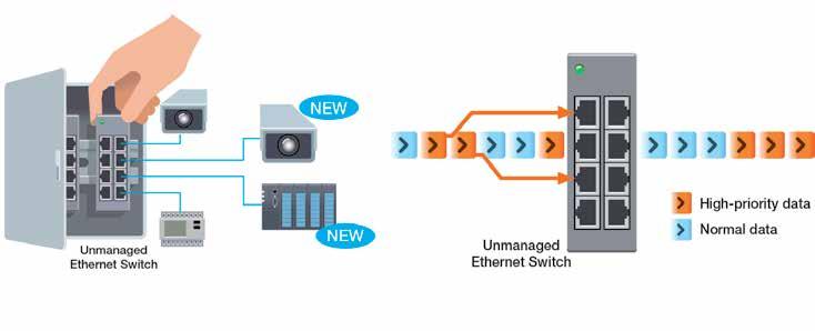
provide power to the device.
Warranty: The warranty offers assurance of quality. It also gives peace of mind in case a unit is defective. Always review the warranty terms and conditions before purchasing the product from any company. Make sure you can receive enough support when a product fails.
Lead time: The lead time for receiving the switch can easily be neglected. It is an important consideration depending on the project requirements. Delays in timesensitive projects are costly and can damage the reputation of the responsible person. Carefully evaluate the lead time and select a reliable vendor. This will help you meet your project deadlines.
Industrial switches, by design, are more sophisticated than commercial ones and are prepared to resist harsh conditions. Below are some points that you can consider when selecting your device.
Operating temperature range: It is important to consider the temperature range at which the switches are going to be used. The device’s temperature can be very low or very high in certain situations. The operating temperature of the switches should be wide enough to cover potentially extreme conditions.
Industrial grade housing: Choosing a switch with ruggedized housing to endure challenging environmental conditions is
vital for an industrial network. The IP code, or ingress protection code, is useful when choosing electrical devices for industrial settings. It can help ensure the protection of the device against the intrusion of objects, dust, or liquids.
It is also worth mentioning, plastic housing switches are good options if you want an affordable and light device. On the other hand, metal housing has better heat dissipation. They also have a better grounding effect when it comes to environments with high electromagnetic noise levels.
Certifications: For certain industries, such as transportation, maritime, railway, etc., additional certification may be required. You can inform yourself of your industry’s

mandatory certifications and ensure that the switches you select conform to those standards.
The performance of a switch can enhance your network’s quality a lot. There are several factors that you can keep in mind before choosing your device.
Broadcast Storm Protection (BSP): A broadcast storm is the accumulation of many broadcast packets in a short period. It can decrease the performance of the network significantly. Finding broadcast stormaffected ports can become very difficult, considering that unmanaged switches are not detectable in network software. Broadcast Storm Protection prevents network troubleshooting by blocking broadcast traffic when it reaches a certain level. This helps to avoid any difficult issues.
Quality of Service (QoS): In a congested network, you want to make sure that the critical packets are transferred on time. The QoS feature prioritizes network traffic so that important packets can pass first. It guarantees essential applications receive the necessary resources to function correctly.
MAC table size: The MAC table is a storage place for the MAC addresses of network devices. This helps the switch to transfer data quickly to the correct ports. When this table is full, the switch broadcasts traffic to all available ports in the network. This can be seen as a security threat. You can prevent this issue by calculating your network’s required MAC table size.
Switch buffer size: The switch buffer is the memory the device uses to store the data frames/packets it receives before forwarding them further. In some environments, having a bigger data buffer inside the switch will improve communications. Subject to intensive data exchange and an overloaded internal buffer, fewer frames will be dropped by the switch. If the switch drops the frame, it must be re-sent again, and it might cause delays in communication. In other words, the bigger buffer size is better.
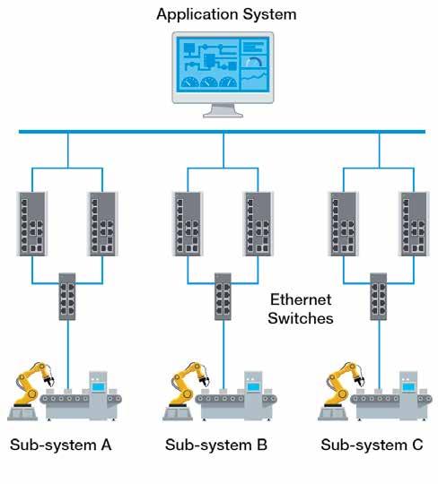
Installation and maintenance
Network installation, because of the large number of available devices, can be complex. There are some considerations in this regard that can save energy and time in installing the switches.
Size of the switch: Control panels or network cabinets are usually loaded with different devices. Fitting switches in control panels sometimes might be challenging or even impossible. In these circumstances, adopting small switches enables flexible

installation and can make room for future network expansion.
Ease of installation: Unmanaged switches are plug-and-play, so configuration is simple. The problem arises during mounting many switches in a network cabinet or control panel. By selecting switches with the appropriate mounting kits, you can make sure that they are easy to mount or unmount.
Overall, choosing a suitable industrial unmanaged switch requires knowledge of your network. This includes the type of devices in the network and the environment in which the switch will be used. A reliable switch can improve network performance and reduce downtime. You should also be aware unmanaged switches offer few security features. If security is your priority it is recommended to use managed switches. Considering above mentioned factors will help you to select an efficient unmanaged switch. So before ordering your next switch take your time and evaluate all of them.
A guide to fiber cable types and costs provides insights into the intricacies of using fiber optic cables in IIoT applications. These cables are now the fastest-growing transmission medium for both new network builds and expansions that require high bandwidth, long distances and immunity to electrical interference.
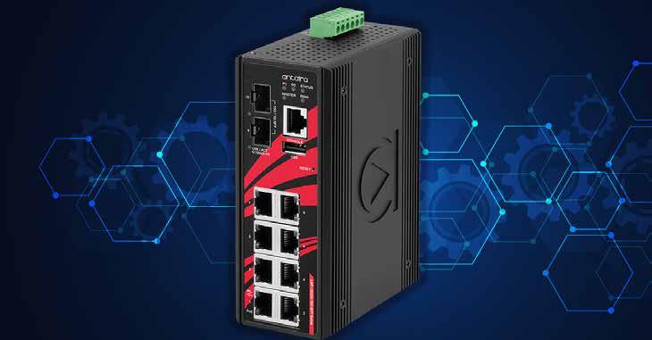
IN THE RAPIDLY EVOLVING LANDSCAPE OF industrial IoT networks, understanding the intricacies of fiber optic cables is essential for IT technicians and plant management alike.
Although fiber has been deployed for more than four decades, several misconceptions remain. At the top of the list is that installing fiber optics is more expensive than copper due to its networking devices, terminations, and cables. Another is that fiber is harder to install and terminate than copper. Last, there’s the fallacy that fiber cables are fragile since they're “made of glass”. We’ll dispel those lingering myths here.
Fiber optic cables are now the fastestgrowing transmission medium for both new network builds and expansions, especially in applications that require high bandwidth, long distances, and immunity to electrical interference. Network backbones transmitting huge amounts of bandwidth-consuming data files almost exclusively rely on fiber.
So, is fiber right for your industrial network?
As the name implies, fiber optic cables carry optical signals using fast-traveling pulses of
light instead of electricity over long distances. At the cable’s core are extremely pure glass fibers the same width as human hair that transmit light photons down the length of cable.
A 125µm layer of glass cladding surrounds the core to guarantee that light is reflected, rather than leaking out at the edges, therefore enabling the signal to travel longer distances without attenuation. Over the cladding is a buffer that keeps the cable's internal glass structure safe from damage and discourages excessive bending. An additional layer of reinforcing fibers shields the core, followed by a rugged plastic jacket.
Fiber is far from fragile. The strength members of fiber cables provide protection against crushing blows, bending forces and, of course, the pulling tension encountered during installation. Reinforcing around the core keeps the cable stiff to maintain the allowable cable-bend radius and prevent kinking when pulling around corners. Once installed, fiber optic cables are sturdier than copper with fewer parts. In fact, a fiber optic cable can last up to 50 years, withstanding
extreme temperatures, high shock, moisture and vibration without degrading.
All this doesn’t mean careless installation won’t damage fiber optic cables. Exceeding bending radius limits or kinking the cable will lead to micro-cracks that increase the potential for degradation. Poorly spliced cable will give rise to fiber movement if splice materials have different characteristics than the cable, such as different thermal expansion coefficients. Malfunctions in fiber optic networks are virtually always due to poor installation, misaligned fusions, or accidental cuts.
Despite the built-in mechanical protection in modern fiber optic cables, some industrial or outdoor plant installations require more protection. In these instances, armored cables are recommended.
Armored fiber optic cables are manufactured to handle abrasion, impact, UV damage and are designed for underground direct burial out of the box. Armored cables can be a cost-effective alternative to running the cable through protective conduit. Conduit installation costs are incurred twice: first, when installing the conduit and second, when installing the cables, hence doubling labor
and material costs. Armored cables cost more than standard fiber cables, but the labor to install them is considerably less.
Fiber optic cables are broken down into two main product categories — single-mode (SM) and multimode (MM).
Single-mode cable has a small diametral core of 9µm that permits only one mode of light to propagate. SM decreases the number of reflections created as light passes through its core, resulting in lowered attenuation and creating the ability for a signal to travel several miles before needing to be enhanced. SM is the preferred choice for long-haul networks, telcos, campus backbone and large enterprises spread over extended areas.
SM is available in two classifications:
OS1: for use in indoor locations over shorter distances and where electrical interference may be greater.
OS2: targeted at outdoor installations with a maximum range of 125 miles. OS2 cables support bandwidth speeds of up to 400 gigabits per second (Gbit/s) over distances up to 80km or further using off-the-shelf optical modules. OS2 is generally more tolerant to flexing and stretching than OS1. Not surprisingly, OS2 cables also tend to be more expensive than their OS1 counterparts.
Multimode (MM) fiber optic cables feature multiple strands, ranging in number from 2 to several hundred, resulting in a wider core (50µm to 62.5µm) that accommodates the transmission of numerous data streams over one cable. However, the larger core has its limitations.
Due to higher signal attenuation, MM cables are unable to handle the same long distances as SM fiber cables, typically 2km or less, so they are used to connect in short range applications. MM developed with a plastic core may be used in place of glass for certain industries, such as mining or sensing applications, while bigger core diameter fiber (called MM200) is necessary in other applications.
Like SM, MM cables are split into several classifications:
OM1: maximum bandwidth of 10 Gbit/s, 100 feet distance (obsolete in ISO/IEC 11801 and TIA 568 standards)
OM2: maximum bandwidth of 10 Gbit/s, 260 feet distance (obsolete in ISO/IEC 11801 and TIA 568 standards)
OM3: maximum bandwidth of 10 Gbit/s, 1000 feet distance
OM4: capable of reaching 1300 ft at 10 Gbit/s and 40 Gbit/s up to 500 feet
OM5: like OM4 but uses different colors of laser light to increase support for greater bandwidth up to 200 Gbit/s or even 400 Gbit/s.
MM should not be confused with “breakout” fiber optic cables. Breakout cables are essentially a group of SM or MM jacketed fibers bound together within an outer jacket. A single connector is shared at one end of the breakout cable with individual connectors on the other. Color-coded cables are "broken out” and therefore enable several connections between network devices with different speed ports, while fully utilizing port bandwidth. Consider, for instance, a switch with a 100G port connected to ten 10G ports. Ideal for patching, breakout cables simplify installation, reduce cable congestion, and improve overall cable management.
In the past, the general rule was MM for short indoor/same building applications while SM was for long distance links and just about everywhere else. That is changing.
Recently, there’s been a big decrease in cost-per-foot for SM cables. Also, the price of SM transceivers has come down considerably, while designs have become more resilient; in the past, an attenuator was required, or you’d risk burning out the receiver if the cable was too short for the laser used.
Both these factors have made SM more cost-efficient for indoor/ same building applications. With 40- and 100-Gbit/s connections becoming commonplace, SM increasingly makes business sense for new installations and network expansions. Single mode electronics are still about 30% more expensive than conventional electronics because they require more complex optical processors to create powerful light sources. However, when factoring in the lower costs of SM cables, the overall expense is similar — yet SM’s performance benefit is dramatically better. SM supports brighter, more powerful light sources with lower attenuation. Its bandwidth is unlimited, at least in theory. Although MM comes in five different cable grades, none of them can match SM’s limitless bandwidth over short or long distances.
In general, fiber remains more expensive than copper in the near term. However, fiber ends up costing less in the long run after factoring in copper’s overlooked costs, maintenance, interference, risk of tampering and replacement expense.
There is no question that installation prices for fiber are higher than those for copper due to the skill required for terminations. But as we said earlier, the cost of fiber cable, hardware, and components is declining. In addition, fiber usually requires less than half the networking hardware, has significantly less downtime, and is less expensive to scale and maintain.
Another big plus is that fiber optic cables are immune to electrical noise. Produced by motors, relays, welders, and other industrial equipment,
electrical noise can seriously interfere with copper cabling. The more distance that copper cabling travels between two points, the more noise it absorbs and the more the signal deteriorates. Data is also more secure with fiber since it does not radiate signals and is nearly impossible to tap, thwarting a potentially expensive cyber-attack. Importantly, fiber makes upgrading unnecessary as network speeds and requirements escalate.
Installed “first costs” have long been the driving force behind selecting a cabling medium. Frequently, these costs become the reason users choose to deploy copper instead of fiber. But with the price of industrial fiber networks rapidly dropping due to the factors described above, there are now both shortand long-term benefits that make fiber a more compelling choice.
Many technicians fear that installing fiber connectors on bulk fiber requires a high level of skill to be done correctly. Today it is not always the case. The old school way involved solvent glue, lots of small pieces, and hand polishing the tip. Besides being difficult and time-consuming, the precision required by this method led to unacceptable levels of light loss and back reflection when performed by a less experienced technician.
Today there are better ways to terminate bulk fiber like using pre-polished connectors, fusion or mechanical splicing, and fiber optic pigtails allowing successful implementation even for beginners. Network technicians can choose the best termination option for their needs by weighing the benefits of each technique. Of course, they can also order factory pre-terminated fiber optic cables in the lengths needed that have already been tested for plug-and-play deployment. That said, field termination or “on-site” termination requires a trained technician adhering to industry standards and using specialized tools. The same goes for splicing broken or severed fiber cables to maintain network integrity.
Like any network technology, fiber terminations are not immune to problems even when performed by a professional. Once a termination is complete, the optical signal must be tested to ensure proper connectivity. Routine troubleshooting will help identify any underlying issues without interrupting network service. Contamination of connector end-faces by dust, dirt and oil is one of the primary causes for signal loss and failure. Poor polishing or incorrect alignment of fibers can also result in signal loss, as can exposure to excessive humidity or caustic chemicals.
Henry Martel, Field Application Engineer, Antaira Technologies.
Learn More
A Centralized Network Controller (CNC) is the centerpiece of a software-defined network (SDN). This article focuses on the CNC's role in production systems, present architectures and key considerations to migrate to these new models and how SW-Defined networks may be applied to ODVA-based industrial automation systems.
A Centralized Network Controller (CNC) provides automated means to deploy, configure, maintain and monitor an industrial network.
DIGITIZATION IS DRIVING MANUFACTURING innovation. Manufacturers are integrating their own and partner-based digital services and capabilities, creating software defined factories to meet these needs. As well, manufacturers are looking to increase flexibility, improve security and reduce maintenance, separating hardware (HW) from software (SW) and virtualizing key industrial assets.
Applying the power of predictive maintenance, artificial intelligence and digital twins optimizes factory operations and improves product quality at an ever increasing pace, creating Software Defined Factories.
IT has already created an SW-Defined Networking (SDN) model. A software defined production network is needed to provide dynamic, resilient connectivity and security: a SW-defined network for the SW-defined factory.
A Centralized Network Controller (CNC) is the centerpiece of a SW-defined network. This article will focus on the CNC's role in production systems and present architectures and key considerations to migrate to these new models. We will discuss how SW-Defined networks may be applied to ODVA-based industrial automation systems.
A Centralized Network Controller (CNC) provides automated means to deploy, configure, maintain and monitor an industrial network. A CNC is a software application that uses a host of networking protocols to perform these functions, in other words it is the core platform for Software Defined Network.
The key benefits of using a CNC and moving to a Software Defined Networking model include:
• Simplify operations and improve operational effectiveness: the SW-based automation of the CNC can consistently, scaleably and efficiently deploy and maintain industrial networks.
• Deliver Consistent Experiences: A CNC offers a single-pane of glass to deploy, manage and monitor the industrial network usable by both IT and OT personnel.
• Deliver insight in network performance: by gathering telemetry data from the network infrastructure and applying machine learning and analytics, the CNC provides assurance that the network is functioning properly and helps reduce downtime by indicating where issues
are and how to resolve them.
• Improve Security and Compliance: A CNC can significantly improve security by automating security policy and provisioning. As well, a CNC can improve consistency and compliance by deploying and analyzing the network configurations on a continuous basis.
All the above are general to networking, specific benefits of an SDN for an industrial network system include:
• VLAN stretching: create extended VLANs to connect devices and applications across an L3- routed network to enable asset virtualization.
• Stretching VLANs also enables the creating of smaller Spanning Tree zones that limits the impact of topology change notifications.
• The SDN model essentially deploys a zones and conduit model specified by industrial security standards (e.g. IEC 62443).
An SDN architecture delivers a centralized, programmable network and consists of the following:
• A controller, the core element of an SDN
architecture, that enables centralized management and control, automation, and policy enforcement across physical and virtual network environments
• An Overlay network is a virtual representation of a network
• An Underlay network represents the actual physical devices and connections
An SDN enables the use of virtual networks (overlay networks) running on a physical network (underlay network); the switches, routers and connections, creating alternative topologies to connect and segment devices, such as industrial automation and control devices. Fabric is a term used to refer to the whole overlay/underlay.
This article will outline some of those key protocols that make up the north/southbound APIs, such as LISP, VXLAN, VRF and SGT.
The underlay network is defined by the physical switches, routers and connections that make up the SDN network. All network elements of the underlay must establish IP connectivity via the use of a routing protocol.
In SDN networks, the underlay switches (edge nodes) support the physical connectivity for users and endpoints. However, end-user subnets and endpoints are not part of the underlay network—they are part of the automated overlay network.
Overlay network
An overlay network is created on top of the underlay network through virtualization (virtual networks) described in the following sections. The data plane traffic and control plane signaling are contained within each virtualized network, maintaining isolation among the networks and an independence from the underlay network. Multiple overlay networks can run across the same underlay network through virtualization. In an SDN, the user-defined overlay networks are provisioned as virtual routing and forwarding (VRF) instances that provide separation of routing tables.
An SDN allows for the extension of Layer 2 and Layer 3 connectivity across the overlay through the services provided by LISP. Layer 2 overlay services emulate a LAN segment to transport Layer 2 frames by carrying a subnet over the Layer 3 underlay as shown in Figure 2.
Layer 3 overlays abstract the IP-based connectivity from the physical connectivity. This can allow multiple IP networks to be part of each virtual network. Each Layer 3 overlay, its routing tables, and its associated control planes are completely isolated from each other.
The following diagram shows an example of two subnets that are part of the overlay network. The subnets stretch across physically
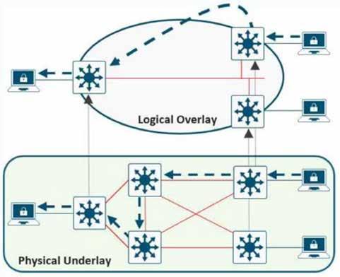
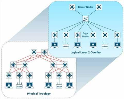
separated Layer 3 devices–two edge nodes. The RLOC interfaces are the only underlay routable address that are required to establish connectivity between endpoints of the same or different subnet within the same VN.
An SDN network consists of 4 key roles.
Any network infrastructure device may play multiple roles at any point in time. The four key roles include:
• Control Plane Nodes
• Edge Node
• Intermediary Node
• Border Node

The SDN fabric control plane node manages the tables used to determine where devices are in the network. In this example, the Control Plane node is the LISP Map-Server and Map-Resolver functionality combined on the same node. The control plane node’s database tracks all endpoints in the fabric site and associates the endpoints to fabric nodes, decoupling the endpoint IP address or MAC address from the location (closest router) in the network.
The control plane node enables the following functions:
Host tracking database: The host tracking database (HTDB) is a central repository of Endpoint ID to Routing Locator (EID-to-RLOC) bindings where the RLOC is simply the IP address of the Loopback 0 interface on a fabric node. The HTDB is equivalent to a LISP site, in traditional LISP, which includes what endpoint ID can be and have been registered.
Endpoint identifiers (EID): The endpoint identifier is an address used for numbering or identifying an endpoint device in the network. The SDN solution supports MAC Address, IPv4 Address, and IPv6 addresses as EIDs.
Map-Server: The LISP Map-Server (MS) receives endpoint registrations indicating the associated RLOC and uses this to populate the HTDB.
Map-resolver: The LISP Map-Resolver (MR) responds to queries from fabric devices requesting RLOC mapping information from the HTDB in the form of an EID-to-RLOC binding. This tells the requesting device to which fabric node an endpoint is connected and thus where to direct traffic.
The SDN fabric edge nodes are the equivalent of an access layer switch in a traditional LAN design. The edge node functionality is based on the Ingress and Egress Tunnel Routers (xTR) in LISP. The edge nodes must be implemented using a Layer 3 routed access design. The Edge nodes provide the following fabric functions:
Endpoint registration: Each edge node has a LISP control-plane session to all control plane nodes. After an endpoint is detected by the edge node, it is added to a local database called the EID-table. Once the host is added to this local database, the edge node also issues a LISP map-register message to inform the control plane node of the endpoint so the central HTDB is updated.
Anycast Layer 3 gateway: A common gateway (IP and MAC addresses) is used at every edge node that shares a common EID subnet providing optimal forwarding and mobility across different RLOCs. On edge nodes, the Anycast Layer 3 gateway is instantiated as a Switched Virtual Interface (SVI) with a hard-coded MAC address that is uniform across all edge nodes within a fabric site.
Mapping of user to virtual network: Endpoints are placed into virtual networks by assigning the endpoint to a VLAN associated to an SVI that is forwarding for a VRF. Together, these make up the Layer 2 and Layer 3 LISP VNIs, respectively, which maintain fabric segmentation even at the control plane communication level.
AAA Authenticator: The mapping of endpoints into VLANs can be done statically or dynamically using an Authentication Server. Operating as a Network Access Device (NAD), the edge node is an integral part of the IEEE 802.1X port-based authentication process by collecting authentication credentials from connected devices, relaying the to the Authentication Server, and enforcing the
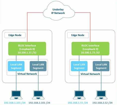
authorization result.
VXLAN encapsulation/de-encapsulation:
Packets and frames received from endpoint, either directly connected to an edge node or through it by way of an extended node or access point, are encapsulated in fabric VXLAN and forwarded across the overlay. Traffic is either sent to another edge node or to the border node, depending on the destination.
When fabric encapsulated traffic is received for the endpoint, such as from a border node or from another edge node, it is de-encapsulated and sent to that endpoint. This encapsulation and de-encapsulation of traffic enables the location of an endpoint to change, as the traffic can be encapsulated towards different edge nodes in the network, without the endpoint having to change its address.
Intermediate nodes are part of the Layer 3 network used for interconnections among the devices operating in a fabric role such as the interconnections between border nodes and edge nodes. These interconnections are created in the Global Routing Table on the devices and are also known as the underlay network. For example, if a three-tier deployment provisions the core switches as the border nodes and the access switches as the edge nodes, the distribution switches are the intermediate nodes.
The number of intermediate nodes is not limited to a single layer of devices. For example, borders nodes may be provisioned on an enterprise edge router resulting in the intermediate nodes being the core and distribution layers as shown in Figure 5.
Intermediate nodes do not have a requirement for VXLAN encapsulation/ de-encapsulation, LISP control plane messaging support, or SGT awareness. Their requirement is to provide IP reachability, physical connectivity, and to support the additional MTU requirement to accommodate the larger-sized IP packets encapsulated with fabric VXLAN information. Intermediate nodes simply route and transport IP traffic between the devices operating in fabric roles.
The fabric border nodes serve as the gateway between the SDN fabric site and the networks external to the fabric. The border node is responsible for network virtualization interworking and SGT propagation from the fabric to the rest of the network.
Border nodes implement the following functions:
Advertisement of EID subnets: BGP (Border Gateway Protocol) is the routing protocol provisioned to advertise the coarse-aggregate endpoint prefix space outside the fabric. This is also necessary so that traffic from outside of the fabric destined for endpoints in the fabric
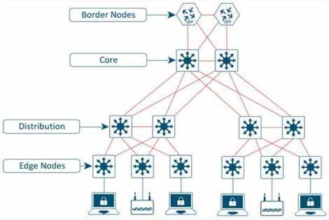
is attracted back to the border nodes.
Fabric site exit point: The external border node is the gateway of last resort for the fabric edge nodes. This is implemented using LISP Proxy Tunnel Router (PxTR) functionality. Also possible is the internal border node which registers known networks (IP subnets) with the fabric control plane node.
Network virtualization extension to the external world: The border node can extend network virtualization from inside the fabric to outside the fabric by using VRF-lite and VRF-aware routing protocols to preserve the segmentation.
Policy mapping: The border node maps SGT information from within the fabric to be appropriately maintained when exiting that fabric. Discussed further in the Microsegmentation section, when the fabric packet is de-encapsulated at border, SGT information can be propagated using SGT Exchange Protocol (SXP) or by directly mapping SGTs into the Cisco metadata field in a packet using inline tagging.
VXLAN encapsulation/de-encapsulation: Packets and frames received from outside the fabric and destined for an endpoint inside of the fabric are encapsulated in fabric VXLAN by the border node. Packets and frames sourced from inside the fabric and destined outside of the fabric are de-encapsulated by the border node. This is similar to the behavior used by an edge node except, rather than being connected to endpoints, the border node connects a fabric site to a non-fabric network.
There are four key technologies, that make up an SDN solution, each performing distinct activities in different network planes of operation: control plane, data plane, policy plane, and management plane.
• Control Plane: Messaging and communication protocol between infrastructure devices in the fabric.
• Data Plane: Encapsulation method used for the data packets.
• Policy Plane: Used for security and segmentation.
• Management Plane: Orchestration, assurance, visibility, and management.
In many networks, the IP address associated with an endpoint defines both its identity and its location in the network. In these networks, the IP address is used for both network layer identification (who the device is on the network) and as a network layer locator (where the device is at in the network or to which device it is connected). This is commonly referred to as addressing following topology. While an endpoint’s location in the network will change, who this device is and what it can access should not have to change.
The Locator/ID Separation Protocol (LISP) allows the separation of identity and location though a mapping relationship of these two namespaces: an endpoint’s identity (EID) in relationship to its routing locator (RLOC).
The LISP control plane messaging protocol is an architecture to communicate and exchange the relationship between these two namespaces. This relationship is called an EID-to-RLOC mapping. This EID and RLOC combination provide all the necessary information for traffic forwarding, even if an endpoint uses an unchanged IP address when appearing in a different network location (associated or mapped behind different RLOCs).
Simultaneously, the decoupling of the endpoint identity from its location allows addresses in the same IP subnetwork to be


available behind multiple Layer 3 gateways in disparate network locations (such as multiple wiring closets), versus the one-to-one coupling of IP subnetwork with network gateway in traditional networks. This provides the benefits of a Layer 3 Routed Access network, without the requirement of a subnetwork to only exist in a single part of the industrial network. Instead of a typical traditional routing-based decision, the SDN devices query the control plane node to determine the routing locator associated with the destination address (EID-toRLOC mapping) and use that RLOC information as the traffic destination. In case of a failure to resolve the destination routing locator, the traffic is sent to the default fabric border node. The response received from the control plane node is stored in the LISP map-cache, which is merged to the Cisco Express Forwarding (CEF) table and installed in hardware.
VXLAN is an encapsulation technique for data packets. When encapsulation is added to these data packets, a tunnel network is created. Tunneling encapsulates data packets from one protocol inside a different protocol and transports the original data packets, unchanged, across the network. A lower-layer or same-layer protocol (from the OSI model) can be carried through this tunnel creating an overlay. In an SDN, this overlay network is referred to as the fabric.
VXLAN is a MAC-in-IP encapsulation method. It provides a way to carry lower-layer data across the higher Layer 3 infrastructure. Unlike routing protocol tunneling methods, VXLAN preserves the original Ethernet header from the original frame sent from the endpoint. This allows for the creation of an overlay at Layer 2 and at Layer 3 depending on the needs of the original communication. For example, Wireless LAN communication (IEEE 802.11) uses Layer 2 datagram information (MAC Addresses) to
make bridging decisions without a direct need for Layer 3 forwarding logic.
SDN networks may also place additional information in the fabric VXLAN header including alternative forwarding attributes that can be used to make policy decisions by identifying each overlay network using a VXLAN network identifier (VNI). Layer 2 overlays are identified with a VLAN to VNI correlation (L2 VNI), and Layer 3 overlays are identified with a VRF to VNI correlation (L3 VNI).
Any encapsulation method is going to create additional MTU (maximum transmission unit) overhead on the original packet. As show in the figure below, VXLAN encapsulation uses a UDP transport. Along with the VXLAN and UDP headers used to encapsulate the original packet, an outer IP and Ethernet header are necessary to forward the packet across the wire. At minimum, these extra headers add 50 bytes of overhead to the original packet.
A policy plane operates by creating logical groupings using two key concepts: Virtual Networks with Virtual Routing/Forwarding (VRFs) and Forwarding and Scalable Groupt Tags (SGTs). The goal is to assign an VRFs and SGTs value to the packet at its ingress point into the SDN network. An access policy elsewhere in the network is then enforced based on this tag information deployed by the CNC or a security policy server.
An SGT is a form of metadata and is a 16-bit value assigned by the CNC or a security policy server in an authorization policy when user, device, or application connects to the network.
The fabric VXLAN encapsulation method is used by both the data plane and policy plane. In the policy plane, the alternative forwarding attributes (the SGT value and VRF values) are encoded into the header and carried across the overlay.
The Management plane’s role is to configure and monitor the SDN. The key protocols for managing an SDN include RESTCONF, NETCONF, SNMP and the YANG data models that represent the configuration and management settings for the concepts.
What does this mean for the ODVA ecosystem?
The technologies and concepts for much of this SDN were created for data center virtualization, which is a key aspect of most cloud models. These concepts enable seamless creation and distribution of workloads within the network. The benefits of an SDN include improved operational effectiveness, enhanced security, consistent experience and flexibility. Applied to industrial networks, these concepts may also accelerate the use and integration of cloud and virtualization technologies in production environments.
Key considerations for ODVA’s EtherNet/IP based devices and communication include:
• EtherNet/IP traffic can natively traverse SDN networks. Note that CIP-Sync (Precision Time Protocol) and CIP Motion may not effectively perform as PTP has not been integrated, tested and validated with many SDN deployments.
• Future enhancements for Layer-3 Time Sensitive Network concepts, such as the IETF’s DetNet initiative use aspects of SDN networks, such as VXLAN.
• Enable virtualization of key components in industrial automation networks.
• The SDN concepts allow for standard means to allow applications (such as an Industrial Automation and Control application) to configure the network for application specific requirements.
Paul Didier, Industrial IoT - Solution Architect. Cisco.
Integrating industrial-grade wireless connectivity enabled chocolate manufacturer, Ulmer Schokoladen, to increase productivity, enhance the agility of production lines and deliver a new level of flexibility. The end result is that they to continue offer customers the best quality products, even in higher-paced production.

GERMAN LEADING MANUFACTURER OF chocolate decorations and ingredients, Ulmer Schokoladen, and global industrial wireless automation technology provider CoreTigo, announce today their cooperation in enhancing the efficiency of chocolate manufacturing operations.
Looking for a way to upscale its production lines, Ulmer Schokoladen turned to CoreTigo, to utilize its IO-Link Wireless solution for automation of chocolate manufacturing processes. Ulmer’s flexible production lines use mobile machines for sealing cartons with finished goods. Moving these machines from one location to another within the manufacturing facility creates complexity, which includes rewiring them for communication with the main control unit in each location.
CoreTigo’s industrial wireless automation solutions enable a quick, simple, and scalable retrofit on Ulmer’s existing machines. By connecting an IO-Link optical proximity sensor on each machine to CoreTigo’s IO-Link Wireless Bridge, the TigoBridge, it enabled wireless real-time communication of product carton counts to the TigoMaster IO-Link Wireless Master unit, and from there to the PLC via PROFINET for
data processing.
This enabled full wireless automation of the process, implemented on several machines, located in different halls. The solution eliminated Ulmer’s dependency on manual counting as well as the complex communication wiring and machine relocations.
Additionally, Ulmer intelligently utilized CoreTigo’s IO-Link Wireless connectivity to wirelessly connect PLCs on the production line. This is done by connecting an IO-Link Wireless Hub (TigoHub) to collect the digital outputs from the secondary PLCs and pass the data back wirelessly to a TigoMaster unit, connected to the main PLC and the factory’s MES system.
By going wireless Ulmer gained several benefits, including:
Flexibility and agility: With the elimination of the cables between the PLC and the machine’s sensors, moving the sealing machines to new locations became quicker and easier, saving valuable time and effort.
Easy deployment: As CoreTigo’s IO-Link Wireless devices offer quick and easy retrofitting of existing machines, switching to wireless required a very low effort and minimal downtime until the machine was up and running again.
Reliability: Being an industrial-grade wireless communication protocol, IO-Link Wireless allows full and ongoing connectivity, even when there is no line of sight between the IO-Link Wireless Bridge and Master, thus contributing to the seamless operation of the machine.
“Integrating CoreTigo’s industrial-grade wireless connectivity enabled us to increase productivity and agility of Ulmer Schokoladen’s production lines by enabling us a new level of flexibility”, said Justus Ulmer, Ulmer Schokoladen CEO, “This enables us to continue offering our customers the best quality products, even in high-pace production.”
About IO-Link Wireless
IO-Link Wireless is a deterministic, low latency (5 msec) and low synchronization rates (10’s of micro seconds), highly-reliable and scalable universal wireless communication protocol. Based on the IO-Link IEC 61131-9 standard, it is designed specifically for factory automation, coexisting with other networks - both wired and wireless.
Application report by Core-Tigo. Visit Website
The future of factory automation lies in leveraging the power of data. By optimising data use and its management, along with embracing AI, manufacturing organisations can benefit from the opportunities to stay ahead in a digitally evolving industrial landscape and quickly adapt to the ever-changing needs of the market.
DATA ANALYSIS AND MANAGEMENT ARE vital for the entire manufacturing sector, doing more than just optimising production processes and identifying the root causes of quality issues. For instance, another example is the significant role they play in reducing energy costs, allowing for more efficient and sustainable operations. Looking beyond individual assets, data sharing between information technology (IT) and operation technology (OT), enable the creation of interconnected facilities that enhance productivity even more.
In the videocast episode “Digital Journey: with a map”, Hartmut Pütz, President of Factory Automation EMEA at Mitsubishi Electric Europe B.V., explores the changing landscape of digitalisation and its opportunities for manufacturing.
Artificial intelligence (AI) is reshaping the manufacturing industry. With the rise in data, AI-driven tools are becoming necessary. They have the power to decode complex situations, to facilitate decision-making processes and offer a complete overview of production processes.
Additionally, data-driven technologies can help manufacturers to optimise customised production. In particular, they can support

companies handle rapid shifts in demand by making forecasting methods more reliable. AI and ‘smarter’ operations allow a more efficient and cost-effective factory operations. Making elements within a factory ‘intelligent’ and focusing on bottleneck applications can greatly enhance productivity
SOURCE: MITSUBISHI ELECTRIC EUROPE
and efficiency. Furthermore, AI’s role in predictive maintenance is extremely valuable for operational cost savings. For example, it can help avoid costly unexpected equipment failure and emergency shutdowns.
While data-driven operations represent the future of the manufacturing industry, most data still isn’t used effectively enough. To address this, Hartmut Pütz suggests the Smart Manufacturing at Kaizen Level (SMKL) model. This uses small steps, like the Kaizen method, for manufacturing improvement and builds on the need for better data utilisation.
The future of factory automation lies in leveraging the power of data. By optimising data use and its management, by embracing AI, manufacturing organisations can benefit from the opportunities to stay ahead in a digitally evolving industrial landscape and quickly adapt to the ever-changing needs of the market.
Learn more by watching videocast episode, "Digital Journey: with a map" by clicking the link below.
Technology report by Mitsubishi.
View Video
Features include integration of AB controllers in edge applications, and connectivity with Siemens CNCs.
edgeConnector integrates AB controllers into edge applications
Softing has announced the expansion of its Docker-based edgeConnector product family with the introduction of edgeConnector AllenBradley PLC, providing access to data from ControlLogix and CompactLogix controllers.
With the new Docker-based software module edgeConnector Allen-Bradley PLC, users can easily connect to their ControlLogix and CompactLogix controllers. The data from the controllers is made available on edge devices or virtual environments via OPC Unified Architecture (OPC UA) and Message Queuing Telemetry Transport (MQTT). This enables flexible integration into on-premises or cloud environments without modifying the existing Programmable Logic Controller (PLC) configuration.
edgeConnector Allen-Bradley PLC is easy to configure locally via an integrated web interface. Alternatively, remote global mass configurations are possible via Representational State Transfer Application Programming Interface (REST API).
There are now five edgeConnector products available for the most common control systems. Besides the new edgeConnector Allen-Bradley PLC, these are edgeConnector Siemens, edgeConnector 840D, edgeConnector Fanuc CNC, and edgeConnector Modbus. All edgeConnector products can be deployed very quickly thanks to containerized technology. They are operated on standard hardware and can be easily managed centrally. The integrated MQTT publisher/subscriber functionality allows Industrial Internet of Things (IIoT) solutions to be set up flexibly. The edgeConnectors support state-ofthe-art security standards such as SSL/TLS, X.509 certificates, authentication, and data encryption. This gives users a simple and secure way to integrate data from production into innovative and flexible IIoT solutions.
dataFEED OPC Suite for access to SINUMERIC 840D CNC machines
The latest version V5.35 of dataFEED OPC Suite offers comprehensive support for SINUMERIK 840D CNC machines as well as the integration of web services.
The dataFEED OPC Suite combines software solutions for OPC Unified Architecture (OPC UA) and OPC Classic communication as well as IoT cloud connection in a single product. With the new SINUMERIC 840D support in the dataFEED OPC Suite V5.35, users can read out all process parameters from the Numerical Control (NC) part, the Programmable Logic Controller (PLC) part, and the drive data of
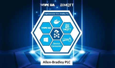
edgeConnector AB PLC provides access to data from ControlLogix and CompactLogix controllers.
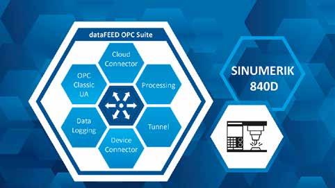
dataFEED OPC Suite V5.35 provides access to SINUMERIC 840D CNC machines.
the machines without having to interfere with the machine configuration.
Another new feature of version 5.35 is web services functionality, which enables direct access to production data via web client applications such as Web Browser, Postman, or Client for URL (cURL) and its integration into IT solutions.
The features of the new dataFEED OPC Suite V5.35 in detail:
• Full support for SINUMERIK 840D Computerized Numerical Control (CNC) machines: The dataFEED OPC Suite can be used to read axis, tool, and program data as well as alarms from the NC section. Status, program sections, and alarms can be read from the PLC section.
• Integration with SIMATIC Siemens S7-300: The suite offers a seamless connection to the integrated SIMATIC Siemens S7-300 for comprehensive control and monitoring.
• Versatile application possibilities of the dataFEED OPC Server CNC: The server can be used as an OPC Classic Server or OPC UA Server and enables the seamless integration of Siemens SINUMERIK CNC controllers into modern Industry 4.0 solutions.
• Provision of production data: The suite enables the provision of production data via the Message Queuing Telemetry Transport (MQTT) or Representational State Transfer (REST) protocols and their transfer to IoT Cloud or Big Data applications on platforms such as Microsoft Azure, Amazon AWS and Siemens MindSphere.
• Integration of production data in IT solutions via web services
Softing
Visit Website
Switches offer new security features and capabilities for use in harsh, industrial environments.
Managed switches support MX-NOS firmware version 4.0
MX-NOS firmware version 4.0 provides added security, diagnostics, and more powerful features for future-proofing industrial networks.
In keeping with its mission to futureproof industrial networks, Moxa announced that it has upgraded its flagship EDS-4000/ G4000 Series of controlled Ethernet switches with support for MX-NOS firmware version 4.0 (V4.0).
The new firmware brings enhanced diagnostics, hardened security measures, and more powerful capabilities to the world’s first IEC 62443-4-2 certified line of Ethernet switches. The EDS-4000/G4000 Series now numbers 68 switch models, all designed to accelerate digital transformation in industrial spaces such as power, transportation, maritime, and factory automation.
Adhering with IEC 62443-4-1, the MX-NOS firmware platform enables expandability in Moxa EDS-4000/G4000 Series switches, allowing for the addition of new functions and features throughout the device's lifetime. By ensuring the switches share a consistent functionality and intuitive interface, MX-NOS V4.0 also enhances the user experience. MX-NOS V4.0 works seamlessly with Moxa MXview network management software to simplify operations throughout industrial operations.
As industrial applications continue to evolve, OT architectures require enhanced network security. Recognizing this, MX-NOS V4.0 brings DHCP Snooping to EDS-4000/G4000 Series switches. A layer 2 security technology, DHCP Snooping filters and drops DHCP traffic determined to be unacceptable, preventing rogue DHCP servers from accessing the OT network using "man-in-the-middle" attacks.
Fast, resilient networks in harsh industrial environments
New ToughNet TN-5300A Series switches comply with mandatory parts of the EN 50155 standard, including temperature, power input, surge, ESD, and vibration.
Designed to extend IoT connectivity into rolling stock, factory robotics, mining and marine applications, ToughNet TN-5300A switches are hardened to withstand exposure to dust, moisture and other damaging elements.
All six models in the TN-5300A Series comply with mandatory test items of the EN 50155 standard including stringent
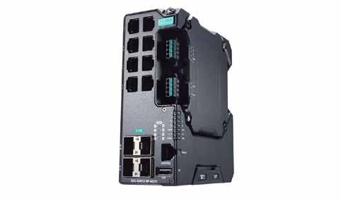
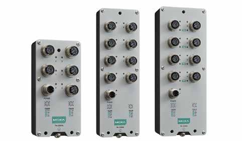
requirements for temperature, power input, surge protection, ESD and vibration, qualifying the switches for deployment on passenger and freight trains.
Available with 5 or 8 Fast Ethernet ports, ToughNet TN-5300A Series switches delivers advanced capabilities similar to other Moxa unmanaged switches yet in an IP54-rated die-cast metal housing.
Key to their reliability is the use of push-pull M12 connectors that ensure exceptionally tight, strong connections and the most dependable resistance against external disturbances like shock and vibration. They also support an extended operating temperature range of -40 to 70°C, plus feature an isolated power input range of 24 to 110 VDC, with overload, reverse polarity, and inrush current protection to achieve stable performance in noisy industrial environments.
To reduce infrastructure costs, the ToughNet TN-5308A Series features several models with up to 8 IEEE 802.3af/at PoE ports to power cameras, sensors, Access Points, VoIP phones and other network PDs (Power Devices).
Classified as Power Source Equipment (PSE), the TN-5308A PoE model, for instance, supplies up to 30 watts of power per port for a total PoE budget of 50.2 Watts.
PoE is critically important on modern trains requiring a high-speed, reliable communication backbone in support of on-board video surveillance, NVRs, Passenger Information Systems, and Wi-Fi access, as well as the demands of multiple trackside and train-to-ground applications.
Moxa
Edge-IO-Link-Masters offer computing power and centrally managed services for the field level.
HILSCHER HAS RELEASED TWO EDGE IO-LINK masters: sensorEDGE FIELD and sensorEDGE. These IP67-rated devices combine computing power and standardized IO-Link sensor connection in one housing. sensorEDGE FIELD and sensorEDGE can be connected directly to Ethernet-based IT infrastructures without the need to intervene in existing communication networks and their controllers - unlike conventional IO-Link master devices.
Hilscher additionally offers a centralized edge management platform via which the devices can be administered locally or via the Internet.
Hilscher’s IO-Link master devices are available in two different versions:
sensorEDGE FIELD: Open computing platform for your own software with optional centralized management sensorEDGE: Complete solution for remote transmission of sensor data via a central platform
Both devices are based on a Linux OS that fulfills aspects of IEC 62443. Their application software is installed and operated securely and encapsulated via container technology. The devices can be configured and managed locally via a web interface or centrally via a platform.
sensorEDGE FIELD
sensorEDGE FIELD is an open data processing platform that customers can customize according to their own requirements.
Advantage: Do-it-yourself for customized IIoT applications. sensorEDGE FIELD allows users extensive customization options based on their specific requirements. The device has two container engines: One for the local and manual deployment of container applications, and a second for interaction with a central management platform.
sensorEDGE FIELD comes with the preinstalled Linux operating system. The user decides which containerized software to run on the devices. A range of free basic containers offers features for IO-Link configuration and IO-Link on MQTT data provisioning. Centralized device management through a single platform is optional and available upon request.
Processing power at the edge: devices can run demanding container applications. In other words, data is not just collected. It is processed at the field level for a decisive advantage.
Containerized software: Using open but
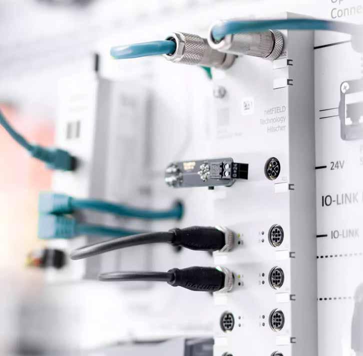
secure container technology, applications are encapsulated into individual containers.
Cloud agnostic: Users are free to choose whether they want the solution to communicate with a local cloud or to communicate with a public cloud over the Internet.
Operation without an Internet connection: sensorEDGE FIELD can be operated in local installations without the need for an Internet connection.
Optional centralized management: An additional option for users who choose solutions from Hilscher’s netFIELD IIoT platform.
sensorEDGE is the solution for the transmission of local IO-Link sensor data with a centralized edge management function.
Advantage: The ready-to-use solution enables instant connection of sensors in less than 5 minutes.
sensorEDGE transfers local IO-Link sensor data to remote MQTT clients. The solution
consists of the IP67-rated device, including IO-Link sockets. All you need is a power source and an Internet connection. No more time-consuming setup.
As soon as the sensors are connected and automatically configured via the IODD (from an Internet file database), the sensor box transmits data to the cloud in 1-second intervals.
Start instantly: As soon as sensorEDGE is powered, the device starts operating. It saves you time.
Cost efficiency: All you need is a power supply and Internet access to integrate the device into your IT infrastructure.
Focused application: Enables data to be analyzed in terms of condition monitoring. Access to data from anywhere: Data can be forwarded to any application where it can be processed to generate added value.
HilscherVisit Website
Balluff’s new asset data provider enables easy capture, preprocessing and provision of data to IIoT applications.
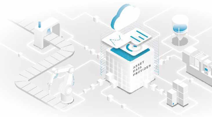
at edge computing level, and put them in the right context and
FROM OT TO IT USING ITS NEW ASSET DATA Provider (ADP), Balluff's goal is to enable the easy capture, preprocessing and provision of data to IIoT applications. Customers can accelerate digitalization projects with an intelligent software solution.
The importance of digitalization and automation is increasing in the industrial world - and with it the intelligent networking between machines, systems, sensors, systems and the cloud. This is where the Industrial Internet of Things (IIoT) comes into play. With its new Asset Data Provider (ADP), the sensor and automation specialist Balluff is now driving forward its customers' IIoT projects: The integrative software-as-a-service solution enables the collection, pre-processing and provision of data at the level of operational technology (OT). Thanks to edge computing, the data is prepared decentrally and reaches the relevant IT systems efficiently, securely and in a resource-saving manner.
“With the Asset Data Provider, our customers can extract, translate, bundle and make compatible different data in the corresponding IT, even in a heterogeneous machine landscape. This breaks down silos
and accelerates digitalization projects in the company – without any complex customer-specific development and manual preparation,” says Artur Nonnenmacher, Software Product Manager at Balluff. Dragand-drop functions, low-code development and a large selection of predefined modules offer uncomplicated and agile development and use, even for users without programming knowledge. Shortened project duration and lower total cost of ownership included.
Because the data is not stored and processed in the cloud, but in the distributed ADP edge nodes, maximum data security is guaranteed. Users also save time and costs: “The so-called one-click deployment enables proof-of-concepts to be rolled out, updated and adapted worldwide,” says Nonnenmacher, “the ADP Cloud significantly simplifies these work steps, which are often still carried out manually - and thus that Entire software lifecycle management.” Furthermore, the asset data provider enables manufacturer-independent and central commissioning, configuration and parameterization of IO-Link masters and devices.
As a smart software solution, the Asset Data
Provider is used for predictive maintenance. The integration of an Enterprise Resource Planning System (ERP) for planning, controlling and supporting business processes also improves the traceability of products in the packaging process.
“Customers from the packaging, food and beverage (PFB) and automotive industries in particular benefit from ADP,” explains Nonnenmacher, “regardless of whether they are still at the beginning of their digitalization journey or are already scaling globally.”
For Balluff, the step represents the next evolution within the industrial revolution. “Our company has been offering reliable data sources such as sensors or IO-Link for many decades. With the Asset Data Provider, we can now select these large amounts of data across manufacturers at edge computing level, put them in the right context and make them available to the IT level," says Nonnenmacher, "we enable our customers to close the gap between OT and IT.
Balluff
Future-ready switch enables simplified network connectivity for Industry 4.0.
Belden has announced its BEETLE Single Pair Ethernet (SPE) Lite Managed Switch from Lumberg Automation.
An extension of Belden’s Single Pair Ethernet portfolio of connectivity products, the new BEETLE switch empowers organizations to reduce network complexity by deploying thinner, lighter SPE cables that provide connectivity via a single pair of wires rather than the two or four pairs required by standard Ethernet.
The BEETLE Lite Managed Switch provides powerful benefits, such as:
Transmits Ethernet up to at least 1 kilometer. Meets the 10BASE-T1L standard for longdistance Ethernet.
Saves space. Supports Ethernet transmission via a single wire pair that is lighter and more compact than traditional Ethernet cables.
Reduces network complexity. Integrate sensors and actuators directly into the network without the need for an additional gateway.
Simplifies configuration and maintenance. Streamline installation and maintenance and reduce operating costs with fewer gateways and protocols in use.
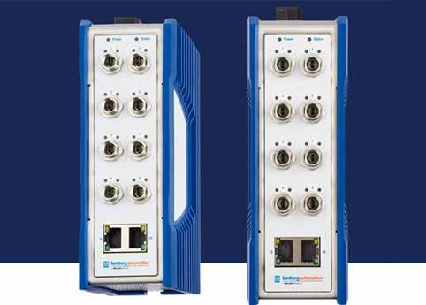
Delivers essential lite managed switch features like VLAN at an optimized priceperformance ratio and lower long-term total cost of ownership.
DFI debuts next-gen industrial motherboard with Qualcomm processor.
DFI has announced the launch of its latest innovation, the DFI QCS051 Industrial Motherboard. Crafted to address the intricate needs of modern industrial automation, the QCS051 integrates the Qualcomm® QCS6490 processor, offering versatility for advanced applications such as Autonomous Mobile Robotics (AMR), Automated Guided Vehicles (AGV), and Box PCs.
Market analysis forecasts the burgeoning potential of AGVs and AMRs to soar to around $20 billion by 2028, accompanied by an anticipated installation base of 2.7 million robots. This surge is chiefly propelled by the logistics and manufacturing domains.
The DFI QCS051 is a compact 2.5-inch Pico-ITX industrial motherboard designed to excel in space-constrained environments. Harnessing the power of the robust QCS6490 processor, the QCS051 delivers exceptional computing power, ensuring smooth operation even in demanding industrial settings. Whether deployed in smart logistics solutions or rugged industrial systems, users can rely on the QCS051 to deliver consistent, reliable performance. Equipped with two M.2 expansion slots,
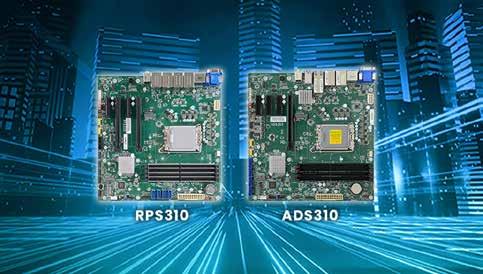
the QCS051 delivers flexibility for additional functionalities. LPDDR5x RAM ensures enhanced performance with increased power efficiency and reduced power consumption, and the HDMI interface provides seamless display connectivity. With CAN-Bus support, the QCS051 can communicate reliably with devices commonly used in industrial automation. Built to withstand
harsh industrial environments, it has a wide temperature range of -25°C to 75°C. The QCS051 features a fan-less design for silent operation and longevity for noise-sensitive environments.
SCADA-based Energy Management System VTScada and IIoT Solution for Industry 4.0.
THE VTSCADA ENERGY MANAGEMENT SOLUTION and the IIoT Solution for Industry 4.0 is a cutting-edge SCADA software that has been supporting the world´s largest missioncritical applications for over three decades. For instance, almost 40% of offshore vessels operating in the Gulf of Mexico are supported by VTScada.
Jose Salgado, Country Manager for Iberia at Delta's Industrial Automation Business Group, said, "In the Iberia market, we are observing a few critical trends, including the digitization and the adoption of smart manufacturing technologies, as well as the adoption of energy management systems for higher production efficiency. Delta´s solutions are designed to address these key market trends of enhanced connectivity and intelligent automation. By integrating our advanced IIoT solutions and automation technologies, we empower businesses to streamline their operations and achieve unprecedented levels of performance."
By integrating data through an Ethernet switch to the VTScada primary server, this solution offers unparalleled visibility and control. Visitors can witness the success of VTScada through real-time remote monitoring of Delta Americas Headquarters and Raleigh Office, showcasing system-wide redundancy, built-in data historian, and remote access capabilities.
Expanding its presence in the Industrial Internet of Things (IIoT) and Industry 4.0, Delta introduces three significant enhancements to its IIoT solutions. The DOP HMI acts as a gateway to DIACloud, facilitating OT data sharing and remote maintenance without the need for VPN routers.
DIAWeb Designer simplifies data visualization and decision-making with its user-friendly dashboard editor, while AS-FFTP01 Function Card offers cost-effective IIoT access for AS PLC users with support for OPC UA server, MQTT client connectivity, and Node-RED web-based dashboard. These innovations demonstrate Delta's commitment to bridging the gap between operational technology (OT) and information technology (IT) layers, enhancing connectivity and intelligence in industrial environments.
Pick-and-Place Articulated Robot: Showcasing Delta's expertise in robotics, this solution demonstrates the efficiency and adaptability of Delta's robotic arms for automating "pick & place" tasks. This solution features the AX-8 as the core motion controller, illustrating how it controls kinematic transformations for articulated robotic arms and manages

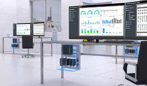
By integrating data through an Ethernet switch to the VTScada primary server, this solution offers unparalleled visibility and control.
various production line devices. With support for multiple communication protocols and cloud connectivity, this solution emphasizes the cost-saving and integration benefits of combining PLC, motion control, robotics, and HMI functions into one compact, efficient package.
AX-5 PLC-Based Motion Controllers: The Delta AX-5 Series represents the cutting edge in motion control, featuring the latest multi-core processor for rapid response and highperformance automation. With its ultra-slim design and support for a wide range of communication protocols, including EtherCAT, CANopen, Profinet, and MQTT, the AX-5 Series offers unmatched flexibility and space savings in automation cabinets.
The AX-5 Series enhances industrial automation with its powerful features and seamless integration capabilities, making it an ideal choice for a broad spectrum of applications.
VP3000 Drive for Fan, Pump, HVAC, Chiller, and Compressor: Highlighting Delta's innovation in drive technology, the VP3000 frequency drive showcases advancements in component lifetime and predictive maintenance. Its low harmonic and built-in EMC filter make it ideal for commercial HVAC and industrial applications.
Delta
New version of the Ixxat SafeT100 allows users to implement safe I/Os for FSoE.
HMS Networks has released a new version of the Ixxat SafeT100 allowing users to implement safe I/Os for FSoE – Functional Safety over EtherCAT. Previously available for PROFIsafe and CIP Safety, the new version supports FSoE according to ETG 5100 V1.2.0.
Ixxat® Safe T100 is an all-in-one safety solution which allows device manufacturers and machine builders to implement configurable, safe inputs and outputs in applications up to SIL 3 and PLe Cat.4.
The Safe T100 is designed to work hand in hand with Anybus® CompactCom. While Anybus CompactCom handles the standard non-safe communication with the EtherCAT network, the Safe T100 handles the safe communication, in this case over FSoE.
Thanks to the implementation of the safe protocol and application layer in Ixxat Safe T100, device manufacturers and machine builders can add functional safety capabilities to their equipment. A typical application for Ixxat Safe T100 is a safe emergency stop function for automation equipment
The Ixxat Safe T100 solution is pre-certified by TÜV Rheinland, and its conformity to the FSoE standard ETG 5100 V1.2.0 has been
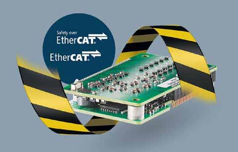
confirmed in the ETG test lab. This enables users to benefit from significantly reduced development time, cost, and risk when realizing safe devices and systems.
Since the Ixxat T100 works together with Anybus CompactCom, the end user will benefit
from a device or machine that provides uses just one communication interface.
New HMI panel display is protected to IP67, and offers maximum flexibility.
KEB Automation has launched a new range of HMI panel displays. The C6 X1 HMI panel can be flexibly attached anywhere on a machine with various mounting options. This eliminates the need for mounting in a control cabinet, allowing users to freely position the HMI near the machine. The IP67-protected HMI is available in four different sizes.
The Web HMI C6 X1 is equipped with capacitive multi-touch and can be installed anywhere in the environment of the machine according to the individual requirements of the machine builder or systems integrator. An advantage here is the particularly simple connectivity of the devices, as the panel supports Power-overEthernet (PoE). The costs for the normally more complex cabling can therefore be reduced. The possibility of installing the Web HMI outside of the control cabinet is made possible due to the high protection class rating of IP67, which enables use in an extended temperature range of -20°C to +55°C without requiring an additional housing. Users can choose between four different panel sizes: 7, 10.1, 15.6 or 21.5 inches.
The HMI systems have a Linux operating

system and are equipped with a Chromiumbased HTML5 browser. This makes them ideal for IIoT edge applications. Machine builders and systems integrators are therefore provided with all the basic requirements for the future of digital manufacturing and can benefit from the advantages of Industry 4.0.
In combination with tools such as HELIO,
the C6 X1 can be used to create an innovative visualisation system. HELIO is an HMI management system that allows users to create intuitive HMIs quickly and easily.
KEB Automation
HMS Networks expands range of next-generation gateways with Anybus Communicator Modbus TCP client. SOURCE:
HMS HAS LAUNCHED A NEW ANYBUS® Communicator™ Modbus TCP Client, offering a high-performance gateway that provides an easy and reliable way to connect Modbus TCP devices to different industrial networks and control systems.
The Modbus TCP market is expanding as customers are transitioning from Modbus RTU to Modbus TCP driven by reduced cabling costs and increased data transfer speeds. This shift has created a demand for a high-performance gateway that can seamlessly integrate Modbus TCP devices with other major industrial networks.
The Anybus Communicator Modbus TCP Client meets this need by providing a reliable solution for connecting Modbus TCP devices to EtherCAT, EtherNet/IP, PROFIBUS, or PROFINET control systems.
Like all Anybus next-generation gateways, the Anybus Communicator Modbus TCP Client provides reliable, secure, and userfriendly technology:
Proven and fast communication using Anybus NP40 technology: The Anybus NP40 industrial network processor ensures that the Communicators meet demanding requirements in terms of industrial performance, reliability, and security. Featuring new hardware and software, the gateways enable instant data transfer – up to 10 times faster than their predecessors. Users can also exchange significantly more data between the networks as the gateways transfer up to 1 500 bytes to and from connected PLCs.
Robust and secure communication: Built using carefully selected industrial components and verified against the CE and UL industry standards, the gateways are designed to handle harsh industrial environments.
To protect users from cyberattacks, the gateways have an onboard physical security switch that prevents unauthorized configuration changes and secure boot functionality to resist attacks and infections from malware.
Fast installation and intuitive configuration: Fast installation and smooth configuration procedures are guaranteed thanks to an optimized housing design, an intuitive GUI, and easy-to-understand documentation.
Installation is simplified thanks to the compact gateway design with forward-facing
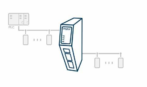

ports and DIN-rail mounting, which allows gateway installation close to connected devices, reducing the amount of required wiring. Users can configure the gateways using drag-and-drop functionality in the web-based GUI, which is accessible via a dedicated Ethernet port on the gateways. In the GUI, users can also monitor network traffic and diagnose issues before they become problems.
Hands-on assistance is also available, as a QR code in the GUI provides a step-bystep installation and configuration guide.
"We are delighted to add the Anybus Communicator Modbus TCP Client gateway to our family of next-generation gateways," said Fredrik Brynolf, Anybus Gateway Product Manager at HMS Networks. "Our customers have expressed a need for a modern gateway with high-speed data transfers to connect Modbus TCP devices
with various control systems. The Anybus Communicator Modbus TCP Client meets this need and, importantly, it’s also incredibly intuitive to use."
Anybus Communicators are available off the shelf as stand-alone ready-toinstall units. Users can personalize the Communicators to meet OEM and brand labeling requirements. The gateways can also be pre-configured to be used as tightly integrated communication components of an automation device or a machine.
The Anybus Communicator Modbus TCP Client is the easiest and most reliable way to connect Modbus TCP devices to control systems.
HMS Networks
Visit Website
Phoenix Contact is extending its industrial network portfolio with WLAN client modules in accordance with the Wi-Fi 6 (IEEE 802.11ax) technology standard. The new modules in the WLAN 1000 series support WLAN gross data rates up to 2,402 Mbps at 160 MHz bandwidth. High-performance and reliable wireless communication networks are a prerequisite for the increasing mobility and flexibility of production and material transport systems in the smart factory or in smart manufacturing. With the new generation of WLAN modules, Phoenix Contact provides suitable products that meet the growing demands placed on modern wireless data transmission. The WLAN client modules offer the latest Wi-Fi 6 technology, high performance, and a particularly high level of security and reliability. With its powerful hardware and modern industrial Wi-Fi 6 board (IEEE 802.11ax), the WLAN 1000 series has up to ten times more data throughput compared to the current modules in the WLAN 1000 product family based on Wi-Fi 4 (IEEE 802.11n). The devices provide WLAN data rates up to 2,402 Mbps gross (160 MHz channel). Despite the considerable performance gains, the compact and proven housing designs are retained. This
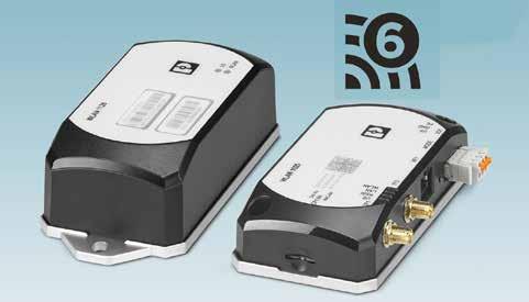
makes it easy to switch to the new generation of WLAN modules.
Compared to previous Wi-Fi generations, Wi-Fi 6 opens up significant improvements in terms of robustness, real-time capability, and efficiency – especially when creating larger networks with many devices, such as AGV or shuttle systems. In addition, the hardware of
the new WLAN modules is already equipped to support the Wi-Fi 6E standard, which will allow wireless communication in the new, largely unused 6 GHz band in the future.
New Siemens software automatically identifies vulnerable production assets.
The cloud-based SINEC Security Guard offers automated vulnerability mapping and security management optimized for industrial operators in OT environments. The software can automatically assign known cybersecurity vulnerabilities to the production assets of industrial companies.
This allows industrial operators and automation experts who don’t have dedicated cybersecurity expertise to identify cybersecurity risks among their OT assets on the shop floor and receive a risk- based threat analysis. The software then recommends and prioritizes mitigation measures. Defined mitigation measures can also be planned and tracked by the tool’s integrated task management. SINEC Security Guard is offered as-a-service (“SaaS”), is hosted by Siemens, and it will be available for purchase in July 2024 on the Siemens Xcelerator Marketplace and on the Siemens Digital Exchange.
Today, industrial operators are tasked with continuously safeguarding their production assets on the shop floor. They need to analyze vendor security advisories, manually match them to the asset inventory of their
factory and prioritize mitigation measures. Because this process is time-consuming and error-prone using the existing tools, factories are running the risk of missing critical vulnerabilities in their assets or producing false-positives.
This can lead to incorrectly configured plant components and inadequately allocated
resources. With the SINEC Security Guard, industrial operators can tackle these challenges without needing in-depth cybersecurity knowledge.
Siemens