14 minute read
Power generation in GPRS of compressor stations
from IGU Magazine October 2016
by IGU
By Behnam Mirzaei, Abdolrahim Najmi, Amir Asghari, Mohammad Reza Goodarzi.
In natural gas transmission systems, compressor stations increase natural gas flowing in pipelines. Wherever there is an end user for natural gas its pressure should be reduced to satisfy their needs. The traditional method for reducing natural gas pressure is to utilise expansion. But there is another newer and more modern method; to utilise turboexpanders. Through this method natural gas is not only expanded and its pressure regulated, but also mechanical power can be produced on the turboexpander’s output shaft which can be converted to electricity via a generator. This paper focuses on natural gas pressure reduction stations (GPRS) of compressor stations. The results show the amount of the fuel saving using turboexpanders.
Technical background
Pressure regulators are widely used in both commercial and residential applications to control the operational pressure of gas. Their task is to reduce a supply pressure to a lower outlet pressure and this reduction is their key characteristic. A pressure regulator is a valve that automatically cuts off the flow of a liquid or gas at a certain pressure. They are used to allow high-pressure fluid supply lines or tanks to be reduced to safe and/or usable pressures for various applications.
When choosing a pressure regulator many factors must be considered. Important considerations include: operating pressure ranges for the inlet and outlet, flow requirements, the fluid, expected operating temperature range, material selection for the regulator components including seals, as well as size and weight constraints.
This reduction of the inlet pressure to a lower outlet pressure leads to a significant reduction of the gas temperature. A water bath heater is used for heating the natural gas and regulating the temperature. It consists of furnace body, burner, smoke fire pipe, heating coiler, chimney, control system and fuel supply system, including an inlet stop valve and regulator. Also, it can be designed with a filter and heater to meet different site conditions. The basic working principle is that water is heated by fuel gas inside the furnace and then the hot water exchanges its heat with the natural gas via a heating coiler.
In natural gas transmission systems, there are compressor stations which their duty is to increase natural gas flowing in pipelines. This increase firstly compensates natural gas pressure loss and secondly provides the natural gas required mass flow at any specific point in the network. Wherever there is an end user for natural gas, its pressure should be reduced to satisfy their needs. This demand can be household, industry, power plant or a compressor station itself needing fuel gas for turbo compressors.
The traditional method for reducing natural gas pressure is to utilise expansion or JouleThomson valves or regulators as described above. But there is another newer and more modern method; to utilise turboexpanders. This way natural gas is not only expanded and its pressure regulated, but mechanical power can be produced on the turboexpander output shaft which can be converted to electricity via a generator.
This article focuses on natural gas pressure reduction stations in compressor stations. Regular compressor stations utilise turbocompressors driven by gas turbines. Each gas
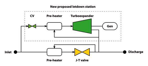
Schematic view of a natural gas pressure reduction station
turbine type has special requirements of fuel pressure and temperature specified by its vendor. To satisfy the fuel gas pressure requirement, there must be a pressure reduction station in each compressor station to regulate inlet gas pressure to that specified requirement.
A schematic view of a natural gas pressure reduction station is shown in Figure 1. The lower line shows the current situation. The pressure regulating device is an expansion valve or a regulator which only reduces gas pressure; no mechanical work is done and the pressure energy stored in the natural gas is lost. The upper line in Figure 1 shows that the expansion valve or the regulator can be replaced with a turboexpander. In this set up, not only is the gas pressure regulated to the required value, but also some shaft work can be produced which can in turn be transformed into electricity through a generator. The new plant has four major elements; a turboexpander, preheater, gearbox and generator.
Turboexpanders are turbines. The reason to designate a specific name for them and to distinguish them from steam turbines and gas turbines is their particular applications. Their operating concept is exactly similar to that of other turbines; they utilise pressure energy of a gas or vapour stream through expanding that
stream and converting the energy released into mechanical work, which in turn can be utilised for mechanical drive applications (as a pump or compressor driver) or power generation applications (connecting to a generator).
As the gas or vapour stream is highly chilled during the expansion process in a turboexpander, sometimes chilling a stream becomes the main reason to utilise a turboexpander and hence the mechanical work produced will be a byproduct in this situation.
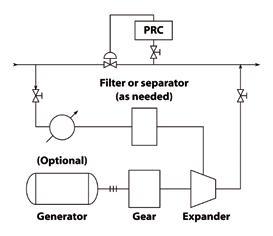
Turboexpanders have been widely used in cryogenic applications. This is mainly due to the characteristic chilling they provide. They are also becoming increasingly popular for power recovery from a hot gas or vapour stream. Our project focuses on another popular use, natural gas pressure reduction/letdown stations. A schematic view of this use is shown in Figure 2 overleaf.
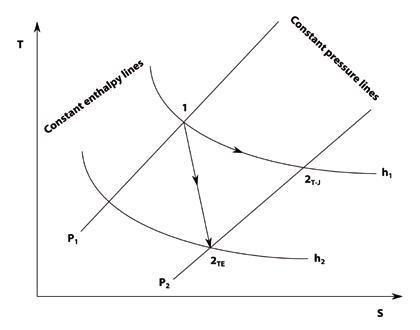
The difference between the operations of an expansion valve or a regulator and a turboexpander is the thermodynamic process that gas follows when the gas stream flows through them. These processes are presented in the temperature-enthalpy (T-s) diagram, Figure 3 overleaf. The thermodynamic process of an expansion valve is along the constant enthalpy line as it is assumed that in an expansion valve there is no change of enthalpy. On the other
c Figure 1.
v Figure 2.
v Figure 3.
Turboexpander in natural gas pressure letdown service (a power recovery cycle) 1
hand, the gas or vapour stream moves along a polytropic process and as there is an enthalpy change, mechanical work can be produced by the turboexpander.
It is concluded from the T-s diagram (Figure 3) that given the same inlet conditions, the temperature of the stream leaving the turboexpander is lower than that leaving an expansion valve. As a general rule of thumb it is proposed that for a 1 MPa reduction in gas stream pressure, its temperature will decrease 4-6°C when the gas is expanded in an expansion valve. The same reduction in pressure through a turboexpander will lead to a temperature decrease of 15-20°C. This feature is very important as a high chilling of the gas stream in the turboexpander can lead to very low temperatures not allowable for the specific gas (because of droplet formation, for example). As a result, there may be a requirement for pre-heating the gas stream before it enters the turboexpander.
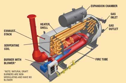
The most common type of heaters used in a natural gas pressure reduction station are water bath heaters. These are an excellent form of indirect heating, efficiently transferring energy to process media. Temperature ranges for the process media and bath fluid are typically lower than those used in other heaters.
The heat transfer media is usually a mixture of water and glycol. Water bath heaters can be utilised as natural draft or forced draft. Typical
Expansion in expansion valves and turboexpanders


A natural draft water bath heater
v Figure 4.
x Table 1.
xx Table 2. efficiency of water bath heaters is 70-75% for natural draft and 80-85% for forced draft.
A water bath heater’s principle of operation is as follows: the burner fires into a submerged fire-tube, located at the bottom of the bath heater shell. Energy is transferred through the fire-tube wall to the surrounding bath fluid (heat transfer media). The bath fluid transfers the required amount of energy into a series of process coils located at the top of the heater
Compressor station data Compressor station simulation results
Nominal capacity
Inlet pressure Exit pressure
91.7 Mm³/d 49 bar 73 bar Height
1519 m Gas turbine type
M5238C shell by means of natural convection.
Water bath heaters are typically atmospheric, with an expansion tank located on top to compensate for the change in bath fluid density with varying bath temperatures. Process bath heaters have few moving parts, require very little maintenance, and can achieve an efficiency of 80% without the use of an economiser. An example of a natural draft water bath
Arrangement
3+1 Gas turbine fuel gas pressure 19 bar Gas turbine fuel gas temperature
25°C
heater is shown in Figure 4.
Each gas turbine power generation
Each gas turbine load
23,000 kW 100% Each gas turbine efficiency
28.86% Each gas turbine fuel consumption
1.773 kg/s
Total fuel consumption / Turboexpander flow 5.319 kg/s
Compressor station simulation
Sample station data
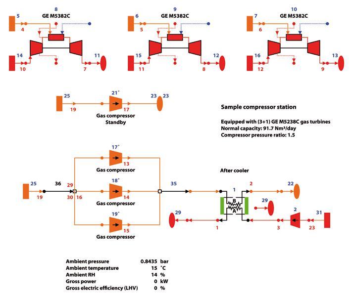
Data for a sample compressor station are presented in Table 1, the schematic view of this station as simulated is shown in Figure 5 and simulation results are included in Table 2.
Compressor station electrical network data
Generally ‘self-generation’ refers to distributed generation technologies (micro-turbines, small gas turbines, wind turbines, photovoltaic systems, fuel cells and internal combustion engines), installed on the customer’s side of the utility meter that provide electricity for either a portion or all of that customer’s electric load. In this regard, turboexpanders represent a ‘super clean’ resource of self-generation because there are no emissions resulting from the pressure drop that enables the technology to produce electrical power. However, in some references, as turboexpander generation relies on fossil fuel inputs, this technology does not qualify as super clean or renewable.
z Figure 5.
v Figure 6.
v Figure 7.
Turboexpander efficiency estimation procedure
The sample station is equipped with a 20 kV to 400 V substation to supply electricity to the station from the national electricity grid. It is fully compatible with the goals of this project since the voltage requirement of turboexpanders in the range we are discussing is also 400 V.
Turboexpander shaft speed selection
Power generation calculations
To gain a better understanding of turboexpander performance and design features a primary estimation of its speed and efficiency is made and presented 1 . This estimation has been performed based on procedures and diagrams provided by leading turboexpander vendors. The iterative procedure of efficiency estimation is shown in the flowchart Figure 6. The procedure should be continued until the difference between the new and old values for the efficiency becomes less than a specified tolerance.
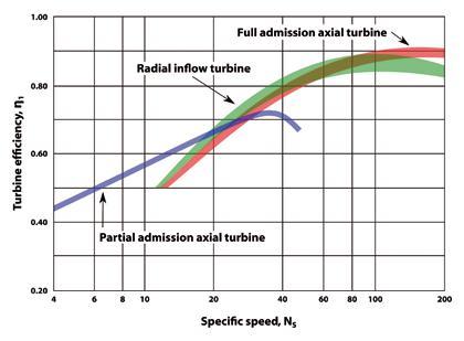
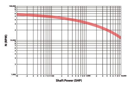
It should be noted that in determining the turboexpander type (Figure 7), for turboexpander specific speed values between 20 and 140, the radial inflow type is recommended from an economic point of view. Figure 8 overleaf determines the maximum allowable turboexpander speed. For higher values of specific speed it can be more economical to reduce the speed; this way the specific speed is also reduced and using a radial inflow turboexpander becomes feasible again.
The results of preceeding calculations are presented for the sample station as

Turboexpander type selection
v Figure 8.
v Table 3.
follows. Besides the values of power generation and heat consumption which are presented, a thermal efficiency is defined according to the first law of thermodynamics which is the ratio of generated electrical power to pre-heater input heat. The required process inputs of the sample station are also included.
Sample station input data and results
A summary of the sample station input data and results of calculations are presented in Table 3.
Estimation of total fuel saving potential
The power generated by turboexpanders means that some power is being added to the elec
tricity network without consuming fuel in
Parameter Station / Turboexpander Inlet Pressure Station / Pre-heater Inlet Temperature Pre-heater Exit / Turboexpander Inlet Temperature Gas Turbines Fuel / Turboexpander Flow Gas Turbines Fuel / Turboexpander Discharge Pressure Gas Turbines Fuel / Turboexpander Discharge Temperature Required Input Heat to Gas Input Heat Considering Pre-heater Efficiency Turboexpander Speed Turboexpander Specific Speed Turboexpander Efficiency Electrical Power Generation First-Law Thermal Efficiency Symbol
P1 T0
T1 mf
P2
T2 Q 0 Q N
NS
ηTE
W
ηth Unit bar °C °C kg/s bar °C kW kW rpm –% kW % Value 49 24 75.7 5.319 19 25 706 1008.6 32214 37.77 78.1 528.6 52.41
Summary of power generation and heat consumption in GPRS of compressor station
Turboexpander (New design) Power Heat 528.6 kW 706 kW Expansion valve or regulator (Current situation) Power Heat 0 kW 294.8 kW
c Table 4.
thermal power plants. Of course, some fuel is consumed to pre-heat the gas before it enters the turboexpander but it should be noted that the expansion of gas in an expansion valve or regulator (which is the current operating case) also reduces its temperature and so requires pre-heating, although the amount of preheating is different. The difference between the pre-heating fuel consumption for a turboexpander and an expansion valve or regulator (new and old cases) is the amount of fuel consumption that is added to a compressor station. If this amount is subtracted from the fuel needed for generating some power equal to the turboexpander power generation, then the total amount of reduction in fuel consumption can be determined. It should be noted that for the sample station, two alternatives of a water bath and electrical heater are considered for expansion valve or regulator (the current situation case). To determine the fuel consumption of electrical heaters the power consumed in the heater should be transformed to electricity in calculations as described below.
The equivalent fuel consumption of turboexpander-generated power (or electrical heater consumed power) is calculated considering an average efficiency of 36.9% for thermal power plants connected to the electricity grid 3 and an average power transmission efficiency of 84%. So the total efficiency would be 31%. To summarise, calculating the equivalent fuel consumption of power generated in a turboexpander: 1 Divide W by 0.31 2 Divide result of 1 by the lower heating value (LHV)
The fuel consumption of water bath preheaters is calculated based on minimum water bath heater efficiency (70%) as explained previously in the technical background above. For electrical heaters an efficiency of 90% is considered. In summary, to calculate the equivalent fuel consumption of heaters: ◆
For water bath heaters:
1
Divide Q0 by 0.7 2 Divide result of 1 by LHV ◆
For electrical heaters: 1 Divide Q0 by 0.9 2 Divide result of 1 by 0.31 3 Divide result of 2 by LHV
The amount of heat needed for gas pressure reduction in a turboexpander case or expansion valve/regulator case together with power generated in thhe turboexpander is summarised in Table 4. It should be noted that heater efficiency is not considered in this table and the calculations for fuel consumption are to be performed as described above.
The fuel consumption for generating equivalent turboexpander electrical power in power plants together with fuel consumption in its pre-heater is presented in Table 5. For the expansion valve or regulator case there
x Table 5.
Equivalent fuel saving and consumption of turboexpander (new design case)
Turboexpander Equivalent power fuel saving (kg/s) 0.034071199 Water bath heater Equivalent heat fuel consumption (kg/s) 0.020152485
v Table 6.
v Table 7.
v Table 8.
Equivalent fuel consumption of expansion valve case
Water bath heater Equivalent heat fuel consumption (kg/s) 0.008414947 Electrical heater Equivalent heat fuel consumption (kg/s) 0.02111277
Total fuel saving
Water bath heater for expansion valve or regulator case Fuel Saving (kg/s) 0.022333661 Fuel Saving (m³/d) 2488 Electrical heater for expansion valve or regulator case Fuel Saving (kg/s) 0.035031484 Fuel Saving (m³/d) 3903
is only fuel consumption in pre-heaters (two types considered) and the data is given in Table 6.
The reduction of fuel consumption is calculated for the sample station and presented in Table 7 according to the following formula:
Fuel saving = [Turboexpander fuel saving;
Table 5] - ([Turboexpander heater fuel consumption; Table 5] - [Expansion valve or regulator heater fuel consumption; Table 6])
Therefore, the total fuel saving in the sample station will be 2,488 standard cubic metres per day (SCMD) for the water bath heater case (in the current situation) and 3,903 SCMD for the electrical heater case (in the current situation). This suggests using water bath heaters instead of electrical heaters in new designs because of the greater fuel saving potential.
References
1 Bloch, Soares, 2001, Turboexpanders and Process Applications, Butterworth
Heinemann. 2 Poživil, 2004, Use of Expansion Turbines in Natural Gas Pressure Reduction Stations,
Acta Montanistica Slovaca Rocˇník 9 (2004), cˇíslo 3, 258-260. 3 Walsh, Fletcher, 2004, Gas Turbine
Performance, Blackwell Science Ltd.
Behnam Mirzaei is Head of Technical Inspection Affairs, Abdolrahim Najmi is Head of Research and Development, Amir Asghari is a Research and Development Engineer and Mohammad Reza Goodarzi is Head of Quality Control at the Iranian Gas Engineering and Development Company.
Cost estimation of gas conditioning systems in turboexpander mode
Investment cost ($)
1,251,125 Water bath heater for expansion valve or regulator case NG Saving (Mm³/y) 0.90812 Saved NG price ($/y) 272,436 Electrical heater for expansion valve or regulator case NG Saving (Mm³/y) 1.424595 Saved NG price ($/y) 427,379
