https://doi.org/10.22214/ijraset.2023.49920

11 III
2023
March
ISSN: 2321-9653; IC Value: 45.98; SJ Impact Factor: 7.538

Volume 11 Issue III Mar 2023- Available at www.ijraset.com

https://doi.org/10.22214/ijraset.2023.49920
ISSN: 2321-9653; IC Value: 45.98; SJ Impact Factor: 7.538
Volume 11 Issue III Mar 2023- Available at www.ijraset.com

Abstract: Six Phase Transmission System has the capacity to increase the transmission capacity by 1.732 times the existing Three Phase System. It is possible to convert existing Three Phase Double circuit transmission line into compact Six Phase transmission line within the existing Right-of-way. Forecasting the demand and supply of Electrical energy gives the alternative solution is Six Phase Transmission system in addition to its several advantages like reduced phase voltage, less corona, declined magnetic field etc. This paper presents the study and analysis of design of transformer for six phase system. Comparison by system count per unit use MATLAB and PSCAD/ EMTDC simulation implemented for both system. Analysis of data carried out for parameters as value phase difference, voltage, current and power in transmission line. Apart from that assessment choosing the best transformer design for six phase system also implemented. From the analysis data performed found line system six phase have successfully produced ascendant as many as 73% in the division transmission line over system double three phase circuit. Apart from obtain that the best connection six phase system to acquire stated ascendant is delta Star delta inverted Star connection and diametrical connection
The need for increasing power transmission capability and more efficient use of right-of ways and the constraints on the availability of land and planning permission for overhead transmission lines have renewed interest in increasing the power density of existing right-of ways. High Phase Order (HPO) technology, which is the use of more than the conventional three phase to transmission corridor is one such technology. The Transmission over the past few decades can be traced on an IEEE paper published by J.R Stewart and I.S Grant. Since that time, the concept of HPO transmission has been described in literature in several papers and report. Amongst the various HPO configurations, six phase configuration appears to be the most promising solution to the need to increase the capability of existing transmission lines and at the same time respond to the concerns related to electromagnetic fields. The main advantage of a six Phase system is that a six Phase line can carry up to 73% more electric power than a 3 phase double circuit line on the same transmission right-of-way. One of the important aspects in the planning of any power system is the design of a reliable and efficient protective scheme. This requires a detailed fault analysis to be carried out for that system. Venkata et al. did pioneering work in the analysis of six phase faulted power system. In an analysis of some fault types that occur in six phase system having presented using six balance sets of symmetrical components.
Beginning of the year 1973, high phase transmission concept been introduced. Further, in the year 1976, Allegheny Power Service Corporation (APS) collaboration with West Virginia University had conducted research analytically design on high phase delivery. This research received fund from National Science Foundation. This effort been seen as a successfully of an alternative to high phase transmission system. Nevertheless, this project finally found abandoned and APS endeavoured to carry out others research in the future. Then in the year 1982, Department of Energy (DOE), United States and New York State Energy Research and Development Authority (NYSERDA) had conducted that study of corona impact and magnetic field for line high transmission phase. To implement this study, high phase transmission line to Test System been build in NYSERDA MALTA, New York. At the end of September 1983, final result from the study showed the six phase transmission could supply poor capacity similar as three phase system with the reduction. At the end of September 1983, final result from the study showed the six phase transmission could supply poor capacity similar as three phase system with the reduction overhead line space to magnetic field and audio noise, reduce delivery structure and lower down the overall cost. Further, in early 1990, Empire State Electric Energy Research Corporation with New York State Electric & Gas (NYSEG) collaboration has implemented demonstration project of High Phase Transmission for research purpose and operations six phase system. This project have short transmission line from Goudey until Oakdale with configuration from double circuit three phase 115kV system to 93kV six phase system with the distance 1.5 miles and being resume to the 115Kv system through two three phase converter 161kV / 115kV with a connection shape Delta/Y(Earth) and connection Delta/Reverse Y(Earth).


ISSN: 2321-9653; IC Value: 45.98; SJ Impact Factor: 7.538
Volume 11 Issue III Mar 2023- Available at www.ijraset.com
In this paper we introduce some of the power systems’ control and operation problems. The management of the modern power system faces mainly optimization tasks. We show some single and multi objective optimization solutions, these are: Decision making; Optimization of the schedule of renewable sources; Energy storage problems; Optimization of the network structure; Definition of the right power mix in single and also multi objective case, Regional energy trade. A large variety of applied technologies is described. In the industry the fast and robust methods are favoured.
Optimal protection and switching device placement
Generation scheduling
Maintenance scheduling
Operative control
Constrained load flow
Power plant operation optimizer
FACTS (Flexible AC Transmission System) control
Dynamic load modelling
Short-Term load forecast
Network reconfiguration and load reduction etc.
Power optimized using six phase transmission:
High Phase Order Transmission requires the number of phase to be extended from the original 3, to 6,12 or above(these being multiples of three to accommodate integration into existing 3 phase network).
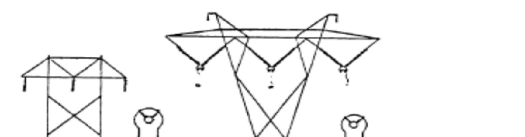
The benefits of an increasing phase order are thus readily apparent. The higher number of phases, the smaller is the phase-phase voltage(assuming constant phase-ground voltage), and thus the smaller is the phase-phase spacing. That means that it is possible to squeeze an ever increasing number of conductors into a servitude comparable to that of an existing 3 phase system, with a resultant dramatic increase in power density.
This is what precisely Barness and Batthold had in mind when they first suggested the use of HPO technologyin line compaction. In addition, by arranging the conductors in a circular array, they achieved the most natural and compact HPO configuration that would utilize corridor space optimally
ISSN: 2321-9653; IC Value: 45.98; SJ Impact Factor: 7.538
Volume 11 Issue III Mar 2023- Available at www.ijraset.com
Due to smaller, lighter structures of high phase order lines, the line cost itself is below that of a conventional 3-phase line, however the added phases require additional transformers and circuit breakers. Previous economic studies have attempted to balance these two effects in a given economic climate, and drive a breakeven distance for which 3 and 6-phase lines cost equal amounts.
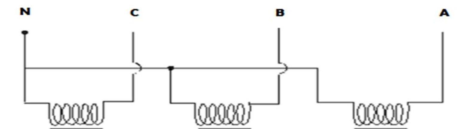
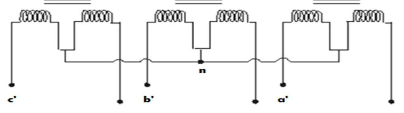
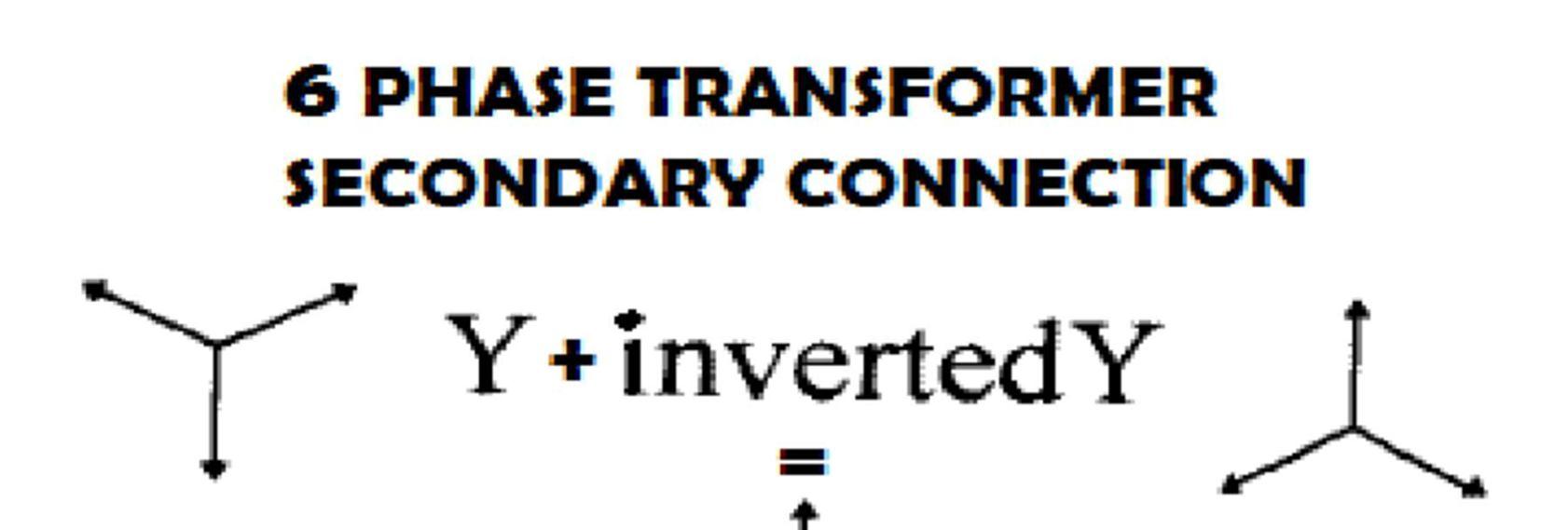
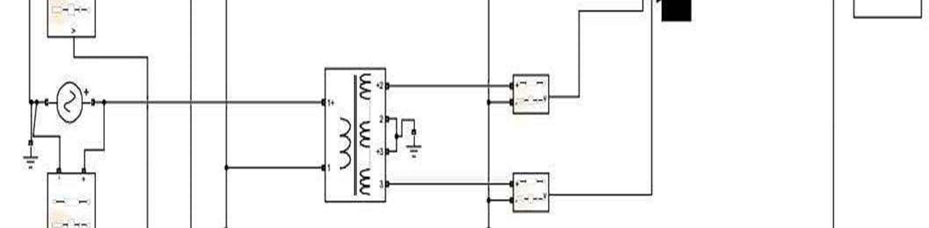
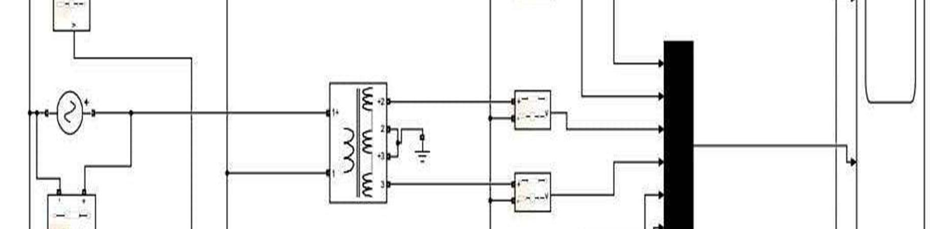
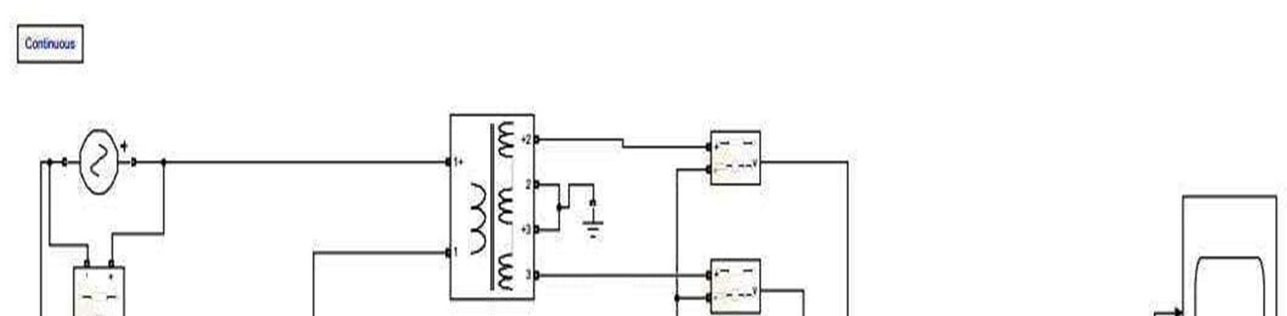
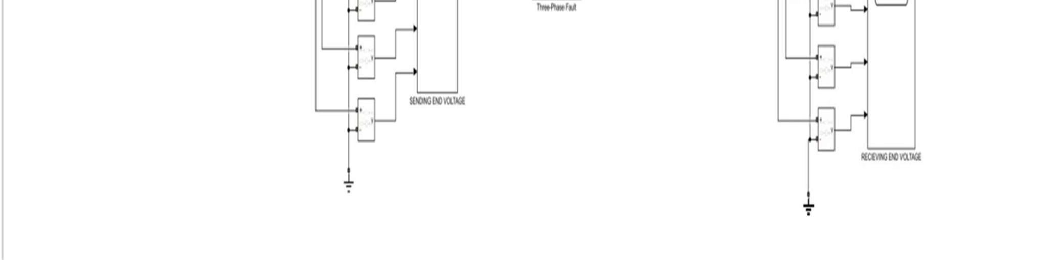
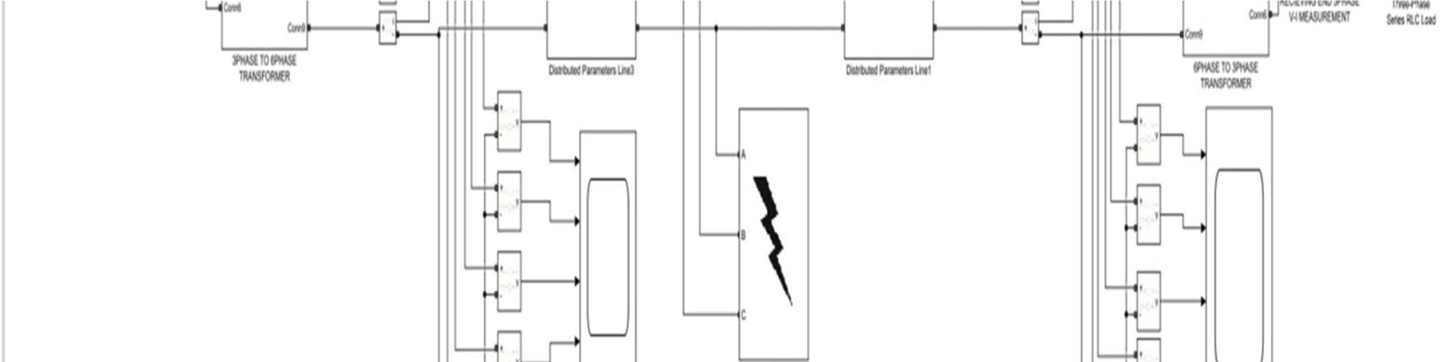
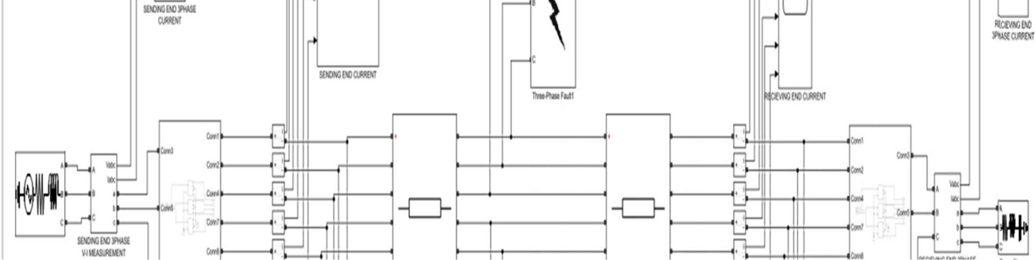
Six phase is generally obtained from existing three phases obtained at the alternator output. A common three phase to six phase conversion is mentioned below. Here the voltage phasor of six phase balanced voltage also explained and also shown the relation between the phase and line voltage of a six Phase transmission system.
The above figure is the circuit diagram of a three phase ‘star (wye)’ connected system converting to a six Phase system. The secondary is that of a six Phase transformer connected in ‘wye-inverted wye’ manner. The common point from the tapping of the secondary coils are connected to ground. The all two ends of each coil Behaves as one phase of the six Phase system.
ISSN: 2321-9653; IC Value: 45.98; SJ Impact Factor: 7.538
Volume 11 Issue III Mar 2023- Available at www.ijraset.com
VAN = VAN ∠0
VBN = VAN -60
VCN = VAN -120
VDN = VAN -180
VEN = VAN -240
VFN = VAN -300
VAB = VAN 0 – VBN -60 =VP 60
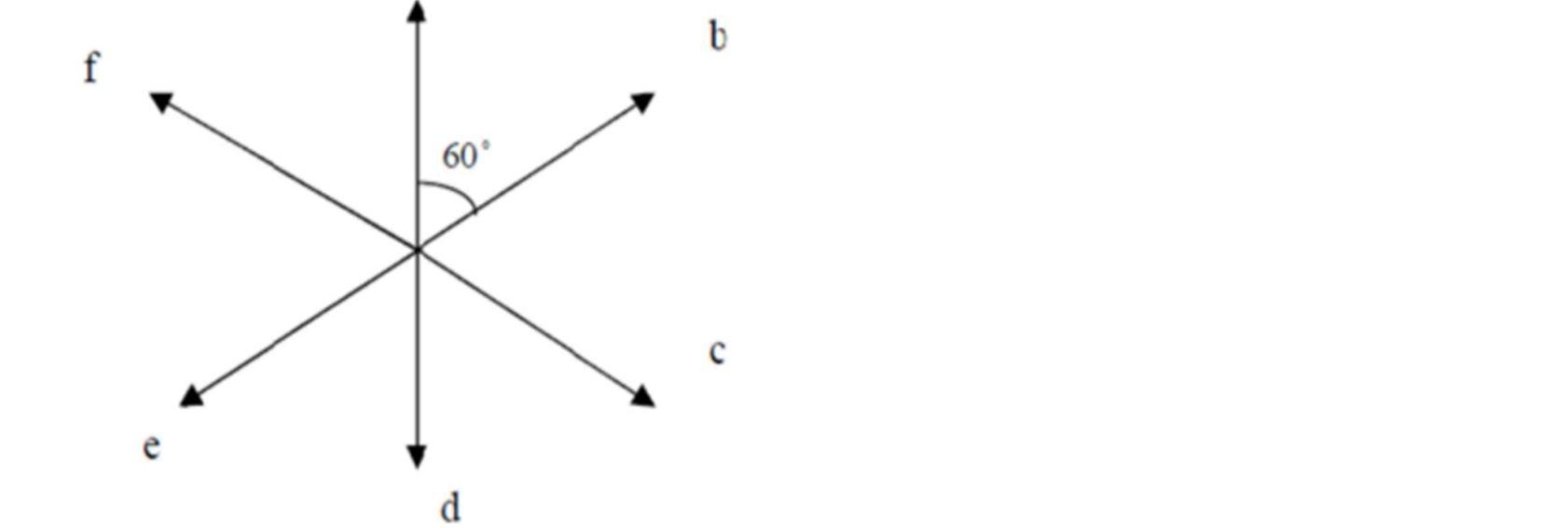

Hence it proved that Vphase = Vline
ISSN: 2321-9653; IC Value: 45.98; SJ Impact Factor: 7.538
Volume 11 Issue III Mar 2023- Available at www.ijraset.com
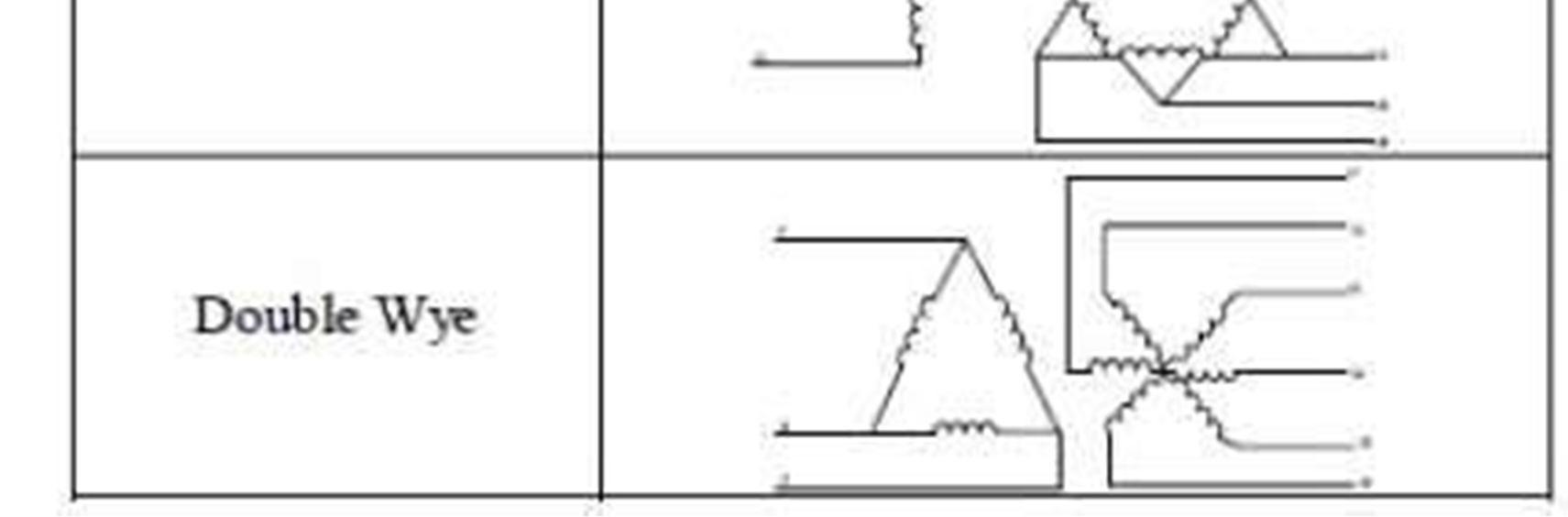
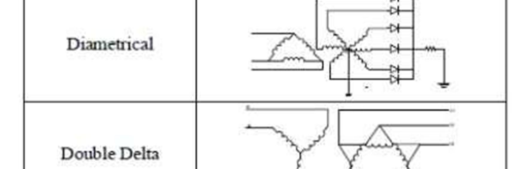
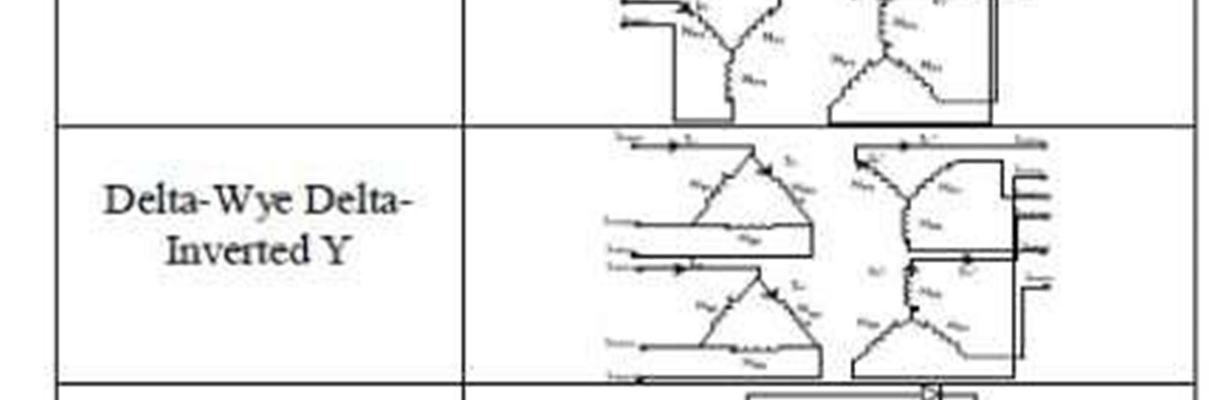
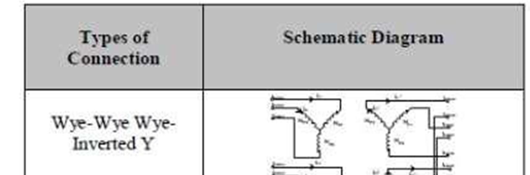
Now the different types of transformer connections of six phase system are shown in the figure below. The transformer connections are similar to that of the three phase transformer connections but with an extended connection form.
Table:-2
Types of 6-phase transformer connection with schematic diagram
ISSN: 2321-9653; IC Value: 45.98; SJ Impact Factor: 7.538
Volume 11 Issue III Mar 2023- Available at www.ijraset.com
Basic feasibility of interconnected 3 phase / 6 phase transmission system has been reported for normal steady state operation, over voltages, insulation requirements, power flow etc., in several studies. The studies reveal several interesting features of six phase transmission system and found to posses better characteristics than those of its 3-phase counter parts. The important findings of these studies are consolidated here for ready reference.
Consider 3 practical cases as follows:
: 138 KV, 3 phase double circuit line configuration
: 230 KV, 3ph transmission line configuration
: 138 KV, 6 phase transmission line configuration
ISSN: 2321-9653; IC Value: 45.98; SJ Impact Factor: 7.538
Volume 11 Issue III Mar 2023- Available at www.ijraset.com
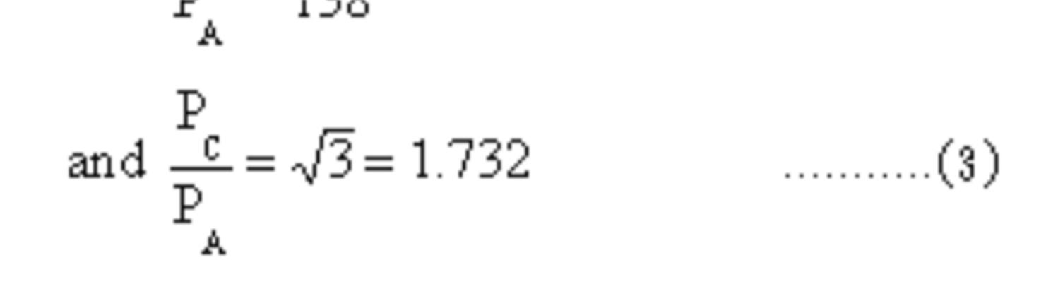
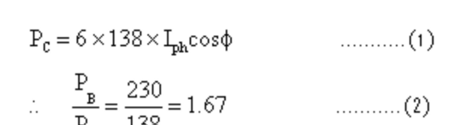
To convert the existing 3phase double circuit line to 6phase transmission line with little modification of the terminal equipment in the substations to provide 3phase / 6phase transformer etc., without changing the transmission towers, without additional rights of way etc,. Then power transferred is given by
Thus from the above equations (2) & (3) it is clear that 6 phase option not only includes less expenditure but also improves the power transfer capability to 1.732 times i.e., 73.2 % more power can be transferred. On the other hand 230KV, upgraded option not only involves more expenditure due to the change in tower design and increased conductor spacing, but also improves the power transfer capability by 1.67 times only from eq. (2). Thus 6 phase line will have more power transfer capability at reduced cost.
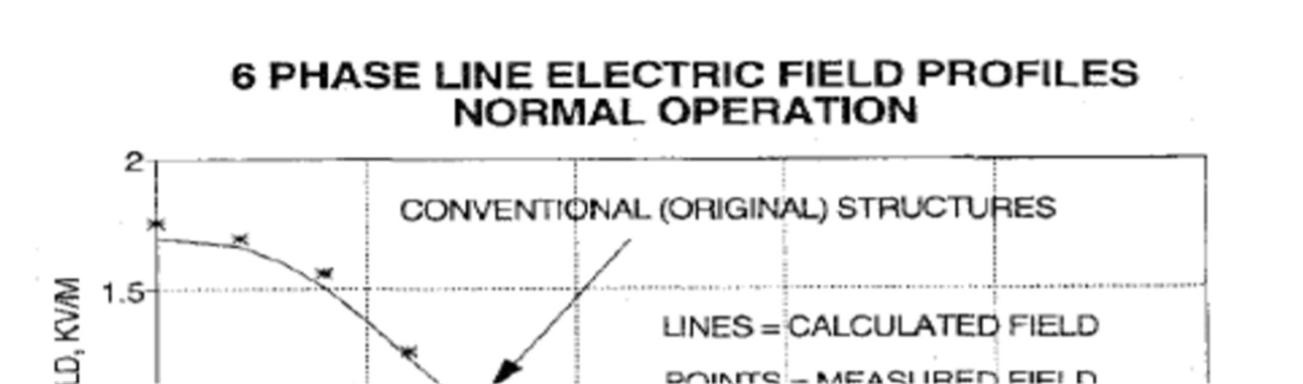
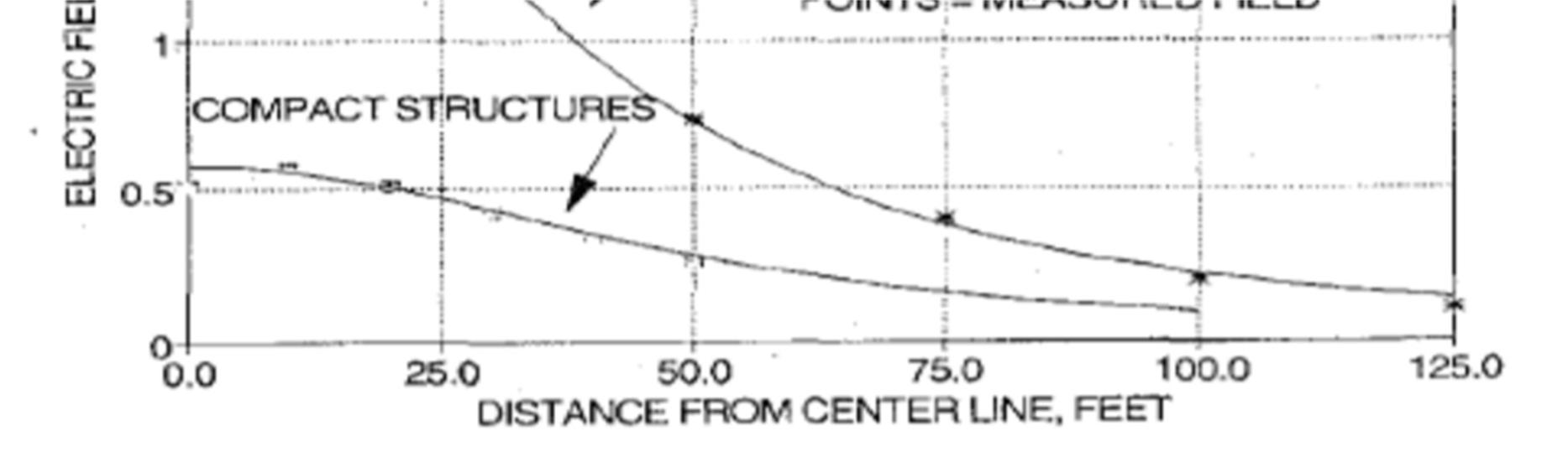
The electric field which is maximum at the conductor surface decreases with phase order whereas the ground electric field will be more since line voltage is equal to the phase voltage for enhanced power. For the same power transfer since the line voltage can be reduced the electric field between the two conductors will be less.


ISSN: 2321-9653; IC Value: 45.98; SJ Impact Factor: 7.538
Volume 11 Issue III Mar 2023- Available at www.ijraset.com
Owing to the reduced conductor spacing & reduced dimensions of 6 phase line the number of lightning strokes to the line are reduced by 20% when compared with the 3 phase counter parts for the same power transfer.
ISSN: 2321-9653; IC Value: 45.98; SJ Impact Factor: 7.538
Volume 11 Issue III Mar 2023- Available at www.ijraset.com
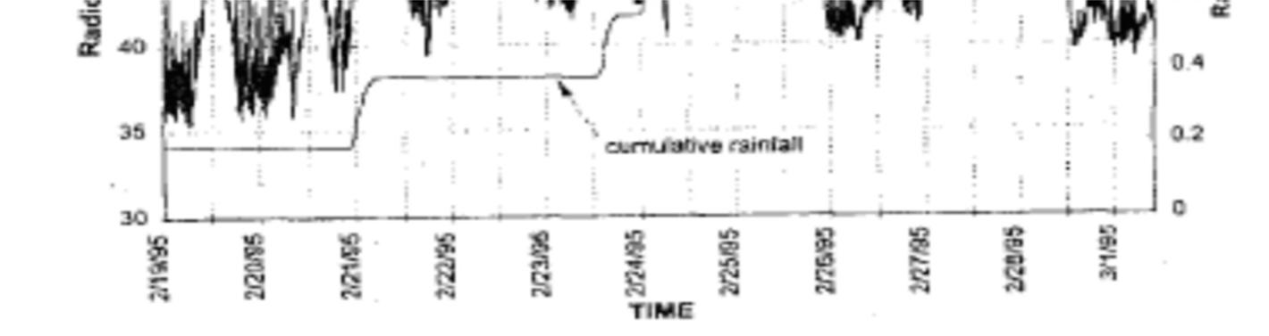
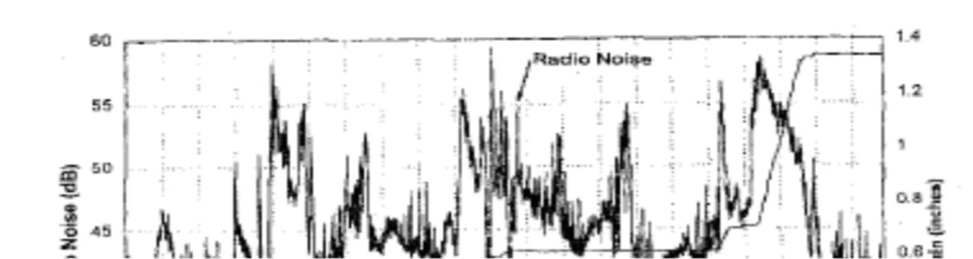
It is proved that 6 phase transmission system will have less radio & audible noise compared to the 3 Phase double circuit line. Radio noise decreases by 8.6 db for a six Phase system as compared to that of a here phase system
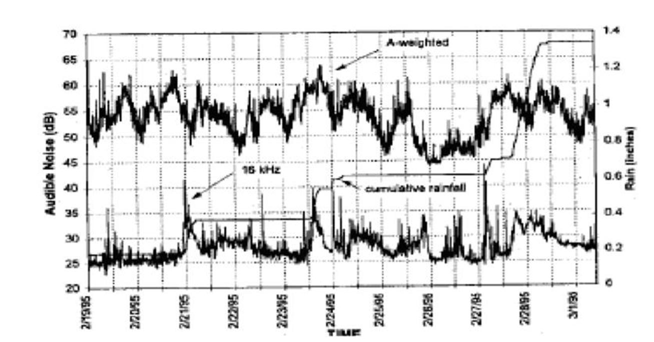
For a six phase system the Audible noise decreases by 12.1 db as compared to three phase system.
E.
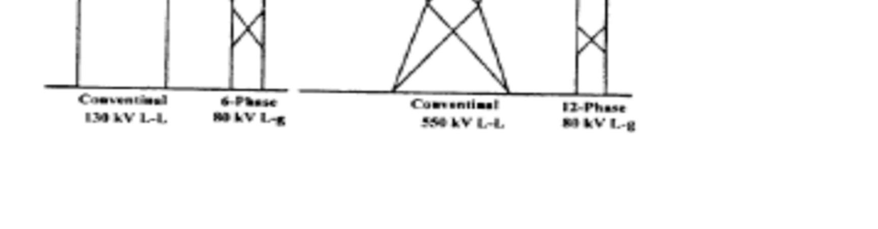
Perhaps the most dramatic effect of switching to a circular array, is the sharp decrease in surface electric field gradient, and related effects. An 80 KV circular was studied first for a 3, and then 6 phase energization without changing the physical structure. In changing from three to six phases, peak surface electric field gradient changed from 14.04 to 10.51KVrms/cm. A more meaningful comparison for HPO was to shrink the phase-phase spacing by a factor of root 3, and this again yielded improvement of 6.2 dB for radio noise, 4.8 dB for audible noise, and 11.7 KV/cm electric gradient. Another practical study shows that a change in energization for a 6 conductor array from a double circuit 3 phase, to a single 6 phase ,reduced the total corona loss on that line from 2046W to 338W per conductor.
The smaller more compact bundle is reported to be far more attractive in appearance, and posses far less of a visual intrusion than conventional lines.
High Phase Order lies are perfectly compatible with the existing 3 phase network. This has been not only theoretically predicted, but shown in practice at the test lines in Malta and Binghamton, NY.
The circular geometry of HPO lines promotes a large degree of field cancellation. This has been studied in numerous papers where 3 phase and HPO were designed to the small SIL capacity and electric field profiles are plotted using standard analytic software, to reveal significantly improved profiles from the HPO lines. Magnetic field profiles are also significantly reduced and are dealt with in a separate paper on the topic. This can be explained by the fact that as one increases the number of phases, the array begins to look more and more like a cylinder, with net zero current flow, and hence zero magnetic field.
It is the power delivered by a transmission line to a purely resistance load equal in value to the surge impedance (Zs) of the line.
ZS = √ /
Since the inductance of 6 phase line is about 90% of that of the 3 phase double circuit line Zs is reduced for 6 phase line.
SIL=√3. √| | . |Vr| *1000KW……………….(4)
where VR = Receiving end line voltage
From eq. (4) since Zs is less for 6 phase the surge impedance loading is more for 6 phase which is an advantage.
ISSN: 2321-9653; IC Value: 45.98; SJ Impact Factor: 7.538
Volume 11 Issue III Mar 2023- Available at www.ijraset.com
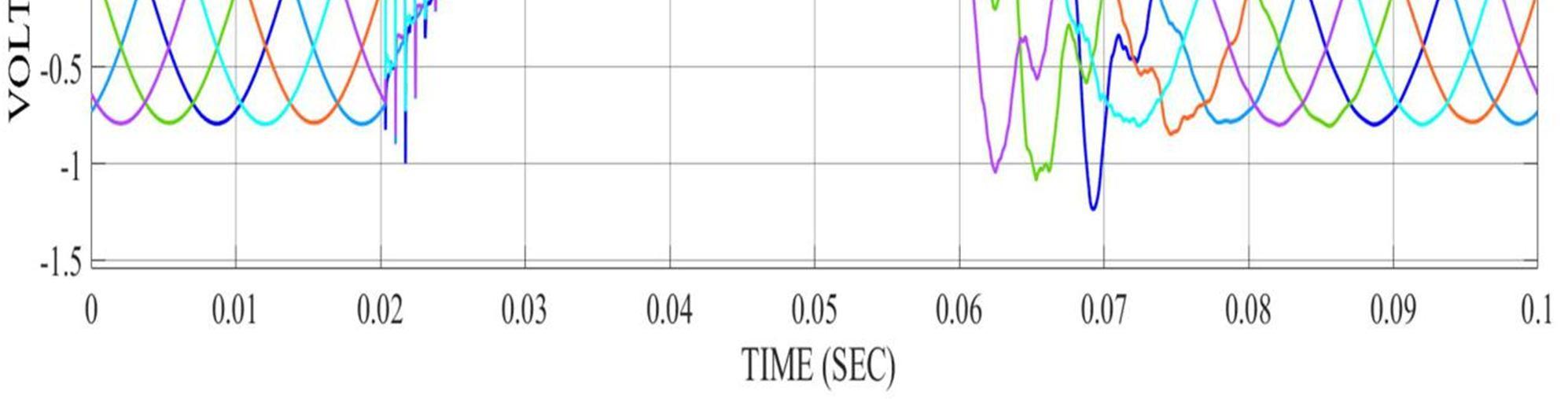
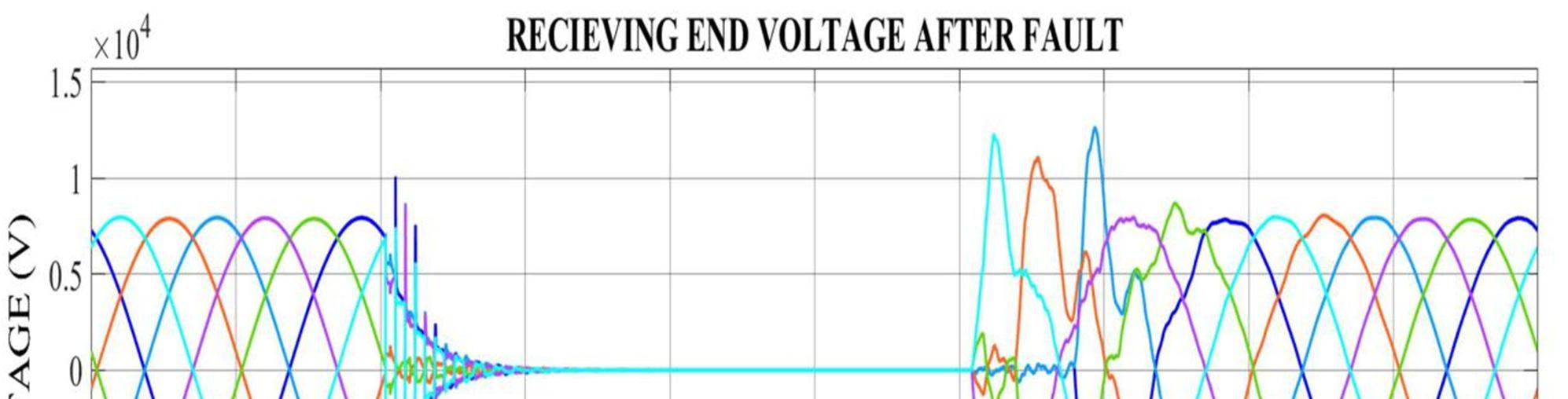
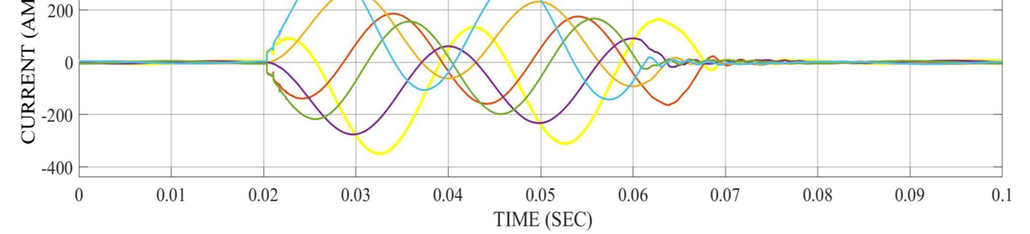
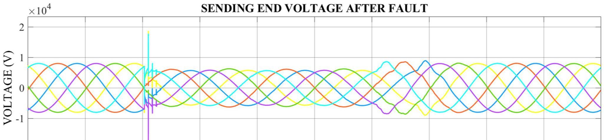
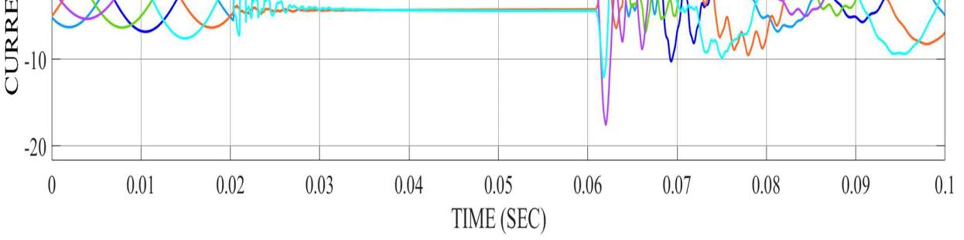
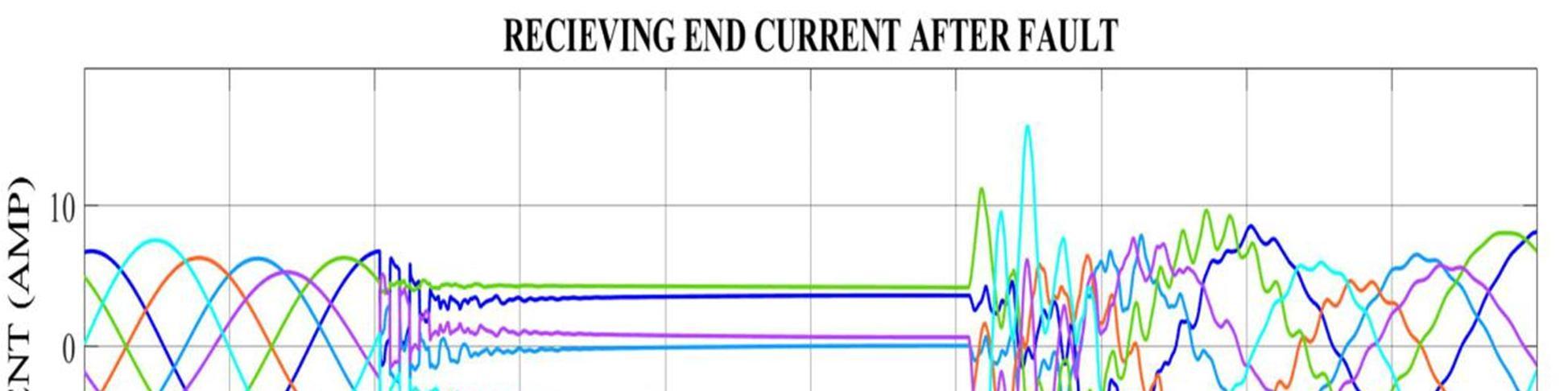
Phase line is said to have more reliability due to the following reasons. More power demand can be met at the load point since power transfer capability is more in 6 phase systems. Voltage regulation and efficiency are better due to less inductive reactance of the 6 phase line for the same power transfer. It is proved that six phase line is more stable for both symmetrical & unsymmetrical faults.
A simple system consisting of generator, transformers, 80 mile transmission line, and a load was studied to gain insight into the degree of current unbalance on the line, as well as negative sequence current occurring in the in the generator for both 3 and 6 phase system. It was found that for both 3 and 6 phase system, negligible generator negative sequence current were produced. The line current unbalance, however was nearly 4% when energized as 3 phase, but fell to below 0.5% for 6 phase. With 6 shield wires, the HPO array had a 0.02% unbalance. Without shield wires, the unbalance was still 0.05%, but with @ shield wires(representing the most unbalanced situation), the figure rose to 0.35%. With a full “roll transposition”, the unbalanced to 0.1% for the 2 shield wire case, and under 0.01% for the other 2 cases.
The phase to ground switching surges are approximately same when 3 phase double circuit line is converted into 6 phase line for the same power transfer. But rate of rise of recovery voltage across the breaker terminals during normal opening is found to be less for 6 phase due to less line voltage for the same power transfer.
There are several benefits which have not been included above, but nevertheless are noteworthy. The whole system is more stable, and gives a more damped response to transient events on the network as well as a greater angular margin to instability. Then , HPO lines operate at a lower voltage than its three phase counterparts, and give better matched ampacities to existing equipment. This is extremely beneficial in countries that do not have the technology to design and manufacture their own EHV equipments.
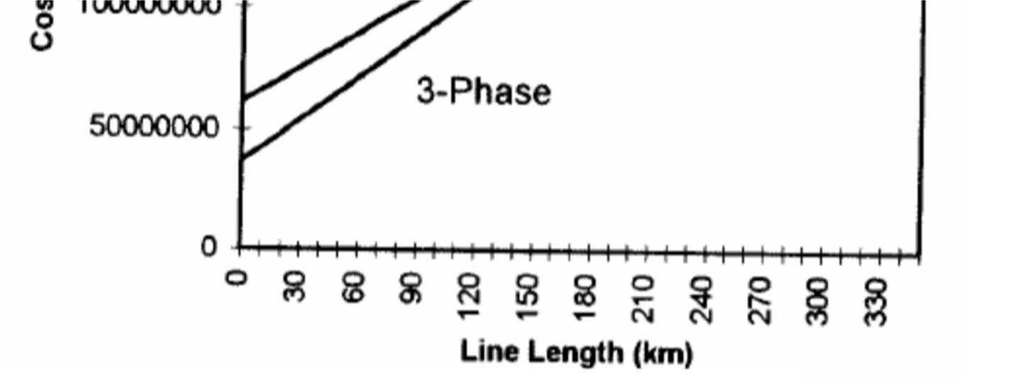
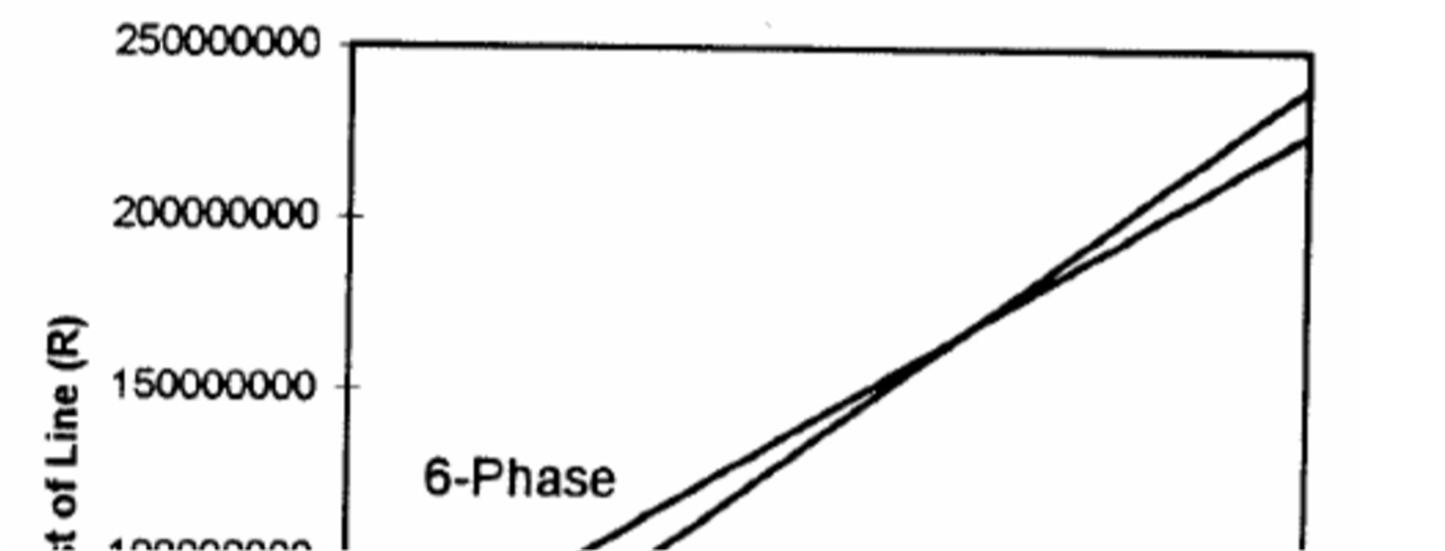
Economy is the most significant parameter to evaluate any project. For a six phase transmission system though the transmission cable cost is minimized or becomes equal with the existing 3-phase system, the end equipments required at the substations and the generating station are of high cost.
The switchgears, the transformers the circuit breakers are more in number as compared to the convenient 3-phase type system. Here will be some extracts from a case study of the first 6-phase system commissioned in South africa to determine the breakeven distance of an 6-phase transmission system
It is the point of distance at which the cost for 6-phase line equals the cost of 3-phase transmission system. This case dealt with an economic breakeven point between a 173KV, 6-phase line, and a 400KV, 3-phase line similar to the Camden-Duvha line but not restricted in length. To make the comparison more even, this line was assumed to connect two 132KV 3-phase systems, which would necessitate transformation for both systems, and associated terminal equipments. Since the substations are essentially similar except for the transformer bays, and line feeder bays, the other costs were assumed equal and only the above elements were taken into account when considering terminal costs. Performing the analysis showed a breakeven distance of 225.86Km and the question now must be asked that is is the distance feasible? To answer this, there is a well known “rule of thumb” which states that he system voltage increases approximately 100KV for every 100Km, and thus a 400KV line should be approximately 400Km long. In light f this fact, a breakeven distance of 225.86Km is well within the line length of a typical 400KV line, and would represent a saving of R19.17million(in south africa currency Rand, data is of year 1998). If one considers further that the cross-rope suspension towers used for the CamdenDuvha line are the cheapest ones used by ESKOM, and represent the state of the art in tower design. The fact is that the line was able to save almost R20 million over a typical stretch becomes a significant achievement.
ISSN: 2321-9653; IC Value: 45.98; SJ Impact Factor: 7.538
Volume 11 Issue III Mar 2023- Available at www.ijraset.com
R = South African Rand(The currency of South Africa)
The breakeven distance was found to be between 200-250 Km. However here Right of Way is not taken into consideration
Right of way is the permission or rights needed to have the transmission cables over the property of any individual, or government, private, public firm. It also includes the land for the towers. The varies from country to country. In INDIA “the electricity (supply) act, 1948” defines all the terms and the regulations for the transmission and distribution of electricity within the INDIAN limits. Here a brief section regarding The Right of Way has been noted to an insight.
THE ELECTRICITY (SUPPLY) ACT, 1948
THE WORKS AND TRADING PROCEDURE OF THE BOARD AND THE GENERATING COMPANY
Section 53: Provision of accommodation and right of way
Where the Board for the purposes of any arrangements which it has made with any licensee under this Act requires accommodation on, in, under or over the premises of the licensee for any works or apparatus to be provided by the Board, the licensee shall, if suitable and sufficient accommodation exists, grant such accommodation free of cost to the Board, or if such accommodation does not exist, it shall be provided upon such terms and conditions as may be agreed between the Board and the licensee.
The Board and any licensee shall each have a right of access at all times to his own property on, in, over and under the property of the other.
The subject of fault analysis on HPO network is very large, and forms topic for numerous papers and reports. It has the potential to quite to quite comfortably fill several MSc. Theses. To begin with, the number of fault combinations rise very quickly with the number of phases. Tables below compares the number of faults combinations for a six Phase system as opposed to a conventional three phase system.
ISSN: 2321-9653; IC Value: 45.98; SJ Impact Factor: 7.538
Volume 11 Issue III Mar 2023- Available at www.ijraset.com
Table : 4


FAULT
Types of faults of six phase transmission system
Types of faults of three phase transmission system
ISSN: 2321-9653; IC Value: 45.98; SJ Impact Factor: 7.538
Volume 11 Issue III Mar 2023- Available at www.ijraset.com
As can be seen, the table is differentiated into a “total number of combinations”, and “significant number of combinations”, This combination comes about due to the fact that faults fall neatly into several “types” based on phase angle between the faulted phases. Another level of complexity is added, though, when several faults occurs simultaneously on the network. This can take the shape of several phase-phase faults, in any combination with several phase-phase-ground faults. This requires a far greater amount of analysis, and is a topic which typically does not present itself as a serious problem in three phase networks. Although moving slightly beyond the scope of this work, it should just be said in passing that this problem has been extensively analyzed by Bhat and Sharma, who have devised a very elegant “method of attack”, involving only two matrix labelled the “phase fault coefficient matrix”, and the “ground fault coefficient matrix”.
ISSN: 2321-9653; IC Value: 45.98; SJ Impact Factor: 7.538
Volume 11 Issue III Mar 2023- Available at www.ijraset.com
ISSN: 2321-9653; IC Value: 45.98; SJ Impact Factor: 7.538
Volume 11 Issue III Mar 2023- Available at www.ijraset.com
It is fair to say that without discriminative protection it will be impossible to operate a mdern power system. The protection is needed to remove as speedily as possible any element of power system in which a faults has developed. So as the fault remains connected, the whole system may be in jeopardy from the tree main effects of the fault.
It is likely to cause the individual generators in the power system, or groups of generators in different stations to lose synchronism and fall out of step with consequent splitting of the system.
Risk of damage to the effected plant. Risk of damage to healthy plant.
So, it is exceedingly important that a proper and effective protective system is designed so that the system does not fall prey to the above abnormalities.
For a six phase transmission system, based on protection criterion which is laid out, three protective schemes are chosen:
Primary (pilot based current differential relay)
Secondary / back up( fiber optics based segregated phase comparison protection)
Tertiary (non communication based commonly known as distance protection)
Due to increased number of phases, the line can be tripped in one of the several ways.
Switching all six phases simultaneously
Switching as sets of three phase lines
Switching one phase at a time
The first option is the simplest and the easiest to achieve, but has the disadvantage of generating the largest magnitude surges, and is somewhat unfavourable since only one phase could be temporarily faulted there would not be any need to isolate the five remaining healthy phases.
The second option is also and economical and has the advantage of retaining symmetrical sets of three phasors. However, it too imposes relatively large stresses on insulation and is only cautiously considered.
Single phase tripping has the double disadvantage of necessitating processing and decision making for correct operation, as well as generating unbalance currents. It is the favoured system through because it allows the five remaining healthy phases to carry the load and imposes far less on insulation than previous method. Thus, even under faulty conditions, the system can carry nearly 84% of total power that is possible. It also adds a tremendous amount of flexibility for protection engineers which simply cannot be achieved in transmission lines.
ISSN: 2321-9653; IC Value: 45.98; SJ Impact Factor: 7.538
Volume 11 Issue III Mar 2023- Available at www.ijraset.com
Based on the progress made on the HPO project through phase 2 the following framework is suggested when undertaking projects to reconfigure existing double circuit lines for Six Phase Operation: Space for transformers and switching equipment including consideration for compact designs. Effect of increased capacity on terminal equipment
Upcoming substations & switchyards must be designed to cater the extra equipments required for three to six phase transmission. Research needs to be done in finding more economical ways for the transformation of existing 3φ system to 6φ system.
With the ever increasing demand of electricity power and difficulty in erecting new transmission lines(more so because of availability of space), high phase transmission system seems to be the inevitable option to cater for the power needs in the near future. Simulation studies of six phase systems have clearly indicated that commercially available relays could cater to the protection of six phase circuits. Hence, Six phase transmission, because of all the advantages which it provides us, can be implemented using the existing three phase double circuit lines and can result in the best possible up gradation that could be done. However research still need to be done in finding out more economical ways of transforming the existing three phase system to six phase system so that the economic constraints could be relaxed to a larger extent. Also, the upcoming substations and switchyards must be designed in such a way that they could cater the extra equipment required for the three phase to six phase transmission.
[1] T.L.Landers , R.J Richeda , E. Krizakas . “High Phase Order Economics: Constructing a New Transmission Line,” IEEE Transaction on Power Delivery, Vol.13, No. 4, 1998. T.F Dorazio . “High Phase Order Transmission”, IEEE 1990.
[2] James R.Stewart , Laurie J.Oppel , Gary C. Thomann , Thomas F..Dorazio , Matthew T.Brown , “Insulation Coordination, Environmental and System Analyisis Of Existing Double Circuit Line Reconfigured To Six Phase Operation”, IEEE Transaction on Power Delivery, Vol. 7, No. 3, 1993.
[3] R. V. Rebbapragada , M.T.Brown , T.F Dorazio , J.R Stewart, “Design Modification And Layout Of Utility Substations For Six Phase Transmission,” IEEE Transaction on Power Delivery, Vol. 8, No. 1.
[4] Alexander Apostolov , William George. “Protecting NYSEG’s sixphase Transmission Line,” New York State Electric & Gas Corporation, 1992.
[5] First A. Zakir Husain, Second B. Ravindra Kumar Singh, and Third C. Shri Niwas Tiwari , Multi-phase (6-Phase & 12-Phase) Transmission Lines performance characteristics, INTERNATIONAL JOURNAL of MATHEMATICS AND COMPUTERS IN SIMULATION, Issue 2, Vol 1, 2007
[6] Venkata , S.S.; Guyker, W.C.; Booth, W.H.; Kondragunta, J.; Saini, N.K.; Stanek,E.K.; Energy Systems Group Department of Electrical Engineering University of Washington, 138-kv, six phase Transmission System, IEEE Trans, Volume PAS-101 Issue 5, May 1982.
[7] Transmission Line Compaction Using High Phase Order Transmission , Jacob Bortnik , A dissertation submitted to the faculty of Engineering , University of Witwatersrand , Johannesburg for the fulfilment of Degree of M.Sc in Engineering.
[8] THE ELECTRICITY (SUPPLY) ACT, 1948, CHAPTER V:the works and trading procedure of the board and the generating company , SECTION 53 : provision of accommodation and right of way
[9] http://www.ukessays.com/essays/engineering/six-phase-converted-transmission-lineengineering-essay.php
[10] Suresh Chandra , Srivasta M. , JSPL , Angul , Power optimization using six phase transmission system , AICTE sponsored National Seminar on Power & Energy system for Future
26th & 27th april 2013,pages 8-10.