IJSRD - International Journal for Scientific Research & Development| Vol. 1, Issue 3, 2013 | ISSN (online): 2321-0613
Combined use of tap-changing transformer and static VAR compensator for enhancement of steady-state voltage stabilities Rutul R. Mehta1 1 P.G. Student, M.E.4th Sem., Faculty of Engineering, Pacific University Udaipur.
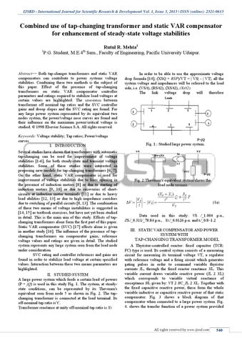
Abstract— Both tap-changer transformers and static VAR compensators can contribute to power systems voltage stabilities. Combining these two methods is the subject of this paper. Effect of the presence of tap-changing transformers on static VAR compensator controller parameters and ratings required to stabilize load voltages at certain values are highlighted. The interrelation between transformer off nominal tap ratios and the SVC controller gains and droop slopes and the SVC rating are found. For any large power system represented by its equivalent two nodes system, the power/voltage nose curves are found and their influence on the maximum power/critical voltage is studied. © 1998 Elsevier Science S.A. All rights reserved. Keywords: Voltage stability; Tap ratios; Power/voltage curves I. INTRODUCTION Several studies have shown that transformers with automatic tap-changing can be used for improvement of voltage stabilities [1-6], for both steady-state and transient voltage stabilities. Some of these studies were interested in proposing new models for tap-changing transformers [6, 7]. On the other hand, static VAR compensator is used for improvement of voltage stabilities due to lines opening in the presence of induction motors [8] or due to starting of induction motors [9, 10] or due to recoveries of shortcircuits at induction motor terminals [11] or due to heavy load abilities [12, 13] or due to high impedance corridors due to switching of parallel circuits [8, 13]. The combination of these two means of voltage instabilities is suggested in [14, 15] as textbook exercises, but have not yet been studied in detail. This is the main aim of this study. Effects of tapchanging transformers alone form the first part of this paper. Static VAR compensator (SVC) [17] effects alone is given in another study [16]. The influence of the presence of tapchanging transformers on compensator gains, reference voltage values and ratings are given in detail. The studied system represents any large system seen from the load node under consideration. SVC rating and controller references and gains are found in order to stabilize load voltage at certain specified values. Interaction between these two means parameters are highlighted. II. STUDIED SYSTEM A large power system which feeds a certain load of powers (P + jQ) is used in this study Fig. 1. The system, at steadystate conditions, can be represented by its Thevenen's equivalent seen from node 5 as shown in Fig. 2. The tapchanging transformer is connected at the load terminal. Its off-nominal tap ratio is’t’. Transformer reactance at unity off-nominal tap ratio is Xt.
In order to be able to use the approximate voltage drop formula [14]; (XSQ + RSP)/VT = | VS| - | VT|, all the system voltage and impedances will be referred to the load side, i.e. (VS/t), (RS/t2), (XS/t2), (Xt/t2). The link voltage drop will therefore
P+jQ
Fig. 1.: Studied large power system.
Fig. 2:Thevenen's equivalent system shows the load node terminals
Data used in this study: VS ⁄_1.004 p.u., ZS.⁄_0.311⁄_78.84 p.u., Xt.⁄_0.0126 p.u. and t.⁄_0.8–1.2 III. STATIC VAR COMPENSATOR AND POWER SYSTEM WITH
TAP-CHANGING TRANSFORMER MODEL
A Thyristor-controlled reactor: fixed capacitor (TCR: FC) type is used. Its control system consists of a measuring circuit for measuring its terminal voltage VT, a regulator with reference voltage and a firing circuit which generates gating pulses in order to command variable thyristor currents IL, through the fixed reactor reactance XL. This variable current draws variable reactive power (IL 2 XL) which corresponds to variable virtual reactance of susceptance BL given by: VT 2 BC_IL 2 XL. Together with the fixed capacitive reactive power, these form the whole variable inductive or capacitive reactive power of that static compensator. Fig. 3 shows a block diagram of that compensator when connected to a large power system. Fig. 4. shows the transfer function of a power system provided
All rights reserved by www.ijsrd.com
540