IJSRD - International Journal for Scientific Research & Development| Vol. 1, Issue 3, 2013 | ISSN (online): 2321-0613
3-Axis Motion Control of CNC Machine based on G-Code, M-Code using FPGA and also Apply Bezier Curve Rajendrasinh Navalsinh Bariya1 Chetanya Sharma2 Prof. Kausal Doshi3 1, 2, 3 Department of Electronics and Communication 1, 2, 3 Marwadi Education Foundation’s Group of Institutions (GTU), Rajkot, Gujarat, India
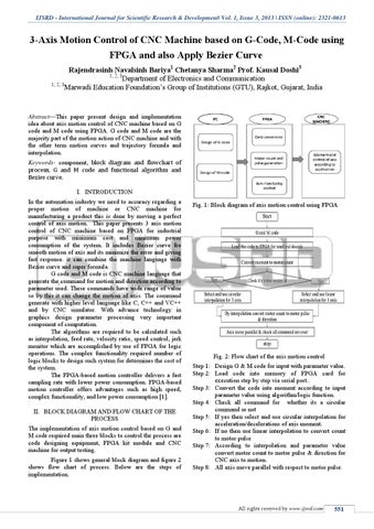
Abstract—This paper present design and implementation idea about axis motion control of CNC machine based on G code and M code using FPGA. G code and M code are the majority part of the motion action of CNC machine and with the other term motion curves and trajectory formula and interpolation. Keywords- component, block diagram and flowchart of process, G and M code and functional algorithm and Bezier curve. I. INTRODUCTION In the automation industry we need to accuracy regarding a proper motion of machine or CNC machine for manufacturing a product this is done by moving a perfect control of axis motion. This paper presents 3 axis motion control of CNC machine based on FPGA for industrial purpose with minimum cost and minimum power consumption of the system. It includes Bezier curve fro smooth motion of axis and its minimize the error and giving fast response. it can combine the machine language with Bezier curve and super formula. G code and M code is CNC machine language that generate the command for motion and direction according to parameter used. These commands have wide range of value so by this it can change the motion of axis. The command generate with higher level language like C, C++ and VC++ and by CNC simulator. With advance technology in graphics design parameter processing very important component of computation. The algorithms are required to be calculated such as interpolation, feed rate, velocity ratio, speed control, jerk monitor which are accomplished by use of FPGA for logic operations. The complex functionality required number of logic blocks to design such system for determines the cost of the system. The FPGA-based motion controller delivers a fast sampling rate with lower power consumption. FPGA-based motion controller offers advantages such as high speed, complex functionality, and low power consumption [1]. II. BLOCK DIAGRAM AND FLOW CHART OF THE PROCESS The implementation of axis motion control based on G and M code required main three blocks to control the process are code designing equipment, FPGA kit module and CNC machine for output testing. Figure 1 shows general block diagram and figure 2 shows flow chart of process. Below are the steps of implementation.
Fig. 1: Block diagram of axis motion control using FPGA
Fig. 2: Flow chart of the axis motion control Step 1: Design G & M code for input with parameter value. Step 2: Load code into memory of FPGA card for execution step by step via serial port.. Step 3: Convert the code into moment according to input parameter value using algorithm/logic function. Step 4: Check all command for whether its a circular command or not Step 5: If yes then select and use circular interpolation for acceleration/decelerations of axis moment. Step 6: If no then use linear interpolation to convert count to motor pulse Step 7: According to interpolation and parameter value convert motor count to motor pulse & direction for CNC axis to motion. Step 8: All axis move parallel with respect to motor pulse.
All rights reserved by www.ijsrd.com
551