
International Research Journal of Engineering and Technology (IRJET) e-ISSN: 2395-0056
Volume: 11 Issue: 12 | Dec 2024 www.irjet.net p-ISSN: 2395-0072

International Research Journal of Engineering and Technology (IRJET) e-ISSN: 2395-0056
Volume: 11 Issue: 12 | Dec 2024 www.irjet.net p-ISSN: 2395-0072
Sunny Patel, Shubham Jogani, Dip Chaklashiya, Dharmik Chodvadiya, Miten Naliyadhara,Vaibhav Monpara
Abstract - The split spoiler design represents a significant advancement in vehicle aerodynamics, improving downforce, stability, and handling at high speeds. By introducinga second, slotted wing positioned at a downward angle, the redesigned spoiler increased downforce from 1094.32 N to 1342.34 N at 300 km/h, while maintaining turbulence intensity at a manageable level, rising slightly from 0.1032% to 0.109903%. Simulations conducted in SolidWorks highlighted the design's ability to moderate turbulence, enhance airflowreattachment, and optimize the lift-to-drag ratio, improving traction and reducing wake instability. These aerodynamic gains lead to better cornering stability, shorter stopping distances, and enhanced safety in dynamic driving conditions. While the design increases drag slightly, its benefits in stability and performance outweigh this drawback. Future improvements could focus on reducing drag further and incorporating lightweight materials for greater efficiency. This research demonstrates the potential of advanced spoiler designs to improve the stability, safety, and overall performance of highspeed vehicles.
Key Words: Downforce, Split Spoiler, Aerodynamics, Turbulence Intensity, Computational Fluid Dynamics (CFD), Vehicle Stability
Aerodynamicsisacriticalfactorindeterminingavehicle’s performance,particularlyathighspeeds,whereforceslike dragandliftsignificantlyaffectstability,handling,andfuel efficiency.Spoilersareessentialaerodynamiccomponents that shape airflow around the vehicle to reduce lift and generate downforce. This downforce enhances grip by increasing the vertical load on the tires, which is vital for improvedtractionduringhigh-speedcorneringandbraking. However, achieving higher downforce often comes at the expense of increased drag and turbulence, necessitating a carefulbalanceforoptimalperformance.
This study focuses on designing and analysing a split spoilersystemthatimprovesdownforcewhileminimizing turbulence. A split spoiler consists of two separate aerodynamic surfaces, strategically placed to optimize airflowandmanagepressuredistribution.Byintroducinga slottedlowerwingatadifferentangletotheoriginaldesign, this configuration aims to reduce turbulence and enhance aerodynamicefficiency.
Using a BMW M4 Coupe as a case study, the original spoiler, which generates 1098.55 N of downforce at 300 km/h, was redesigned to incorporate a split-spoiler configuration.Theredesignedsystemincreaseddownforce to1342.34Nwithaminimalriseinturbulence.Thispaper examinesthetheoreticalprinciplesbehindthesplitspoiler, detailsthedesignandsimulationprocess,andevaluatesits impactonoverallvehicleperformance.
Inourinitialdesign,asimplerearcarspoilerwasmodelled usingSolidWorksandsubjectedtoairflowanalysis.
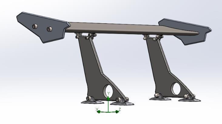
Fig.1 Baseline(conventional)designofrearspoiler
Theresultsindicatedaturbulenceintensityof0.1032% andadownforceof1094.32Natawindspeedof300km/h. Thisdesigneffectivelyutilizedbasicaerodynamicprinciples, generating downforce by creating a pressure difference aboveandbelowthespoiler.
Thedownforce(FL )isgovernedbytheequation
FL=1/2*ρv2/(CL*A) ,
Where: airdensity(ρ), velocity(v), liftcoefficient(CL ), andreferencearea(A)arekeyfactors.
International Research Journal of Engineering and Technology (IRJET) e-ISSN: 2395-0056
Volume: 11 Issue: 12 | Dec 2024 www.irjet.net p-ISSN: 2395-0072
Whilethespoilerprovidedimprovedtraction,stability,and braking performance by increasing vertical tire load, its effectivenesswaslimitedduetoturbulenceandinefficient airflowmanagementathigherspeeds.
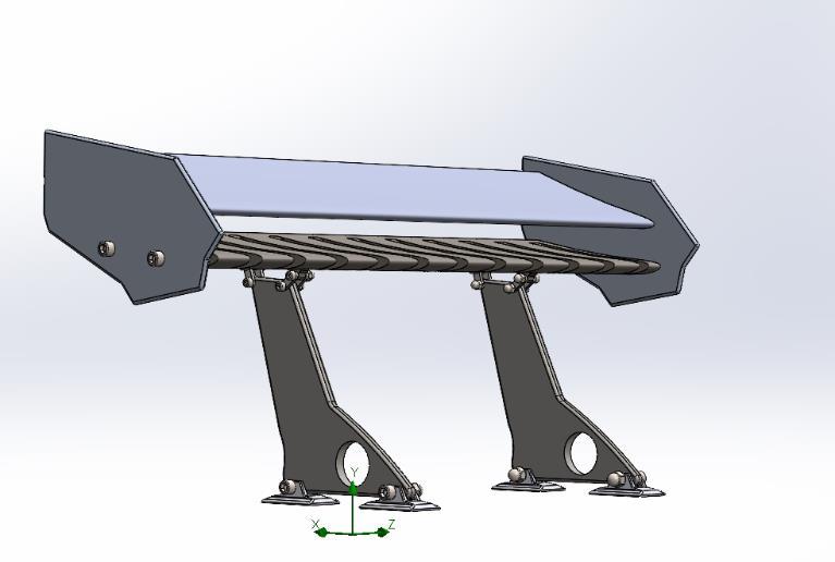
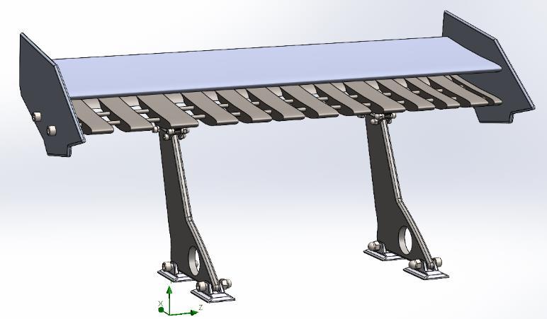
Toenhanceperformanceunderthesamewindspeed,asplit spoiler design is proposed. This improved configuration incorporatesasecondwingpositionedbeneaththeprimary aero foil, angled downward with slotted gaps to better manage airflow. The slotted design moderates turbulence and encourages airflow reattachment, reducing wake instability and increasing aerodynamic efficiency. By optimizing the lift-to-drag ratio, the split spoiler achieves higher downforce while maintaining acceptable levels of turbulenceanddrag.Thisadvanceddesignismoresuitable for high-speed conditions, as it offers enhanced traction, better cornering stability, and shorter stopping distances comparedtotheoriginalspoiler.Adoptingthesplitspoiler design would be a significant step forward in maximizing aerodynamicperformanceandoverallvehiclehandling.
To develop the new split spoiler design, SolidWorks CAD softwarewasusedtomodelandsimulateitsaerodynamic performance.Thebasespoilerwasinitiallydesignedusing standard aerofoil geometries with well-documented aerodynamicproperties,ensuringthattheshapeprovideda
reasonablestartingpointforairflowcontrol.Theredesigned split spoiler introduced a secondary wing positioned beneath the main wing. This secondary wing was angled downwardandincorporatedslottedgapstoenhanceairflow reattachment and reduce turbulence. The combination of these two elements allowed for improved pressure distribution and a more efficient generation of downforce withoutexcessivelyincreasingdrag.
Simulation Setup:
Afterthedesignwasfinalized,computationalfluiddynamics (CFD) simulations were conducted to analyse airflow behaviouraroundthespoiler.Keyboundaryconditionswere setforthesimulation,withairspeedspecifiedat300km/h, corresponding to an inlet velocity of 83.33 m/s. A highresolution mesh was generated around the spoiler to accuratelycapturethecomplexairflowpatterns,particularly inregionspronetoturbulenceandflowseparation.Thek-ε turbulence model, a widely used approach for resolving turbulent flows in aerodynamic studies, was selected to simulatetheinteractionofairwiththespoilersurfacesand thewakeregionbehindthecar.
International Research Journal of Engineering and Technology (IRJET) e-ISSN: 2395-0056
Volume: 11 Issue: 12 | Dec 2024 www.irjet.net p-ISSN: 2395-0072
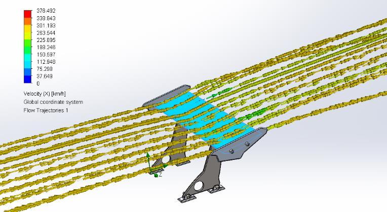
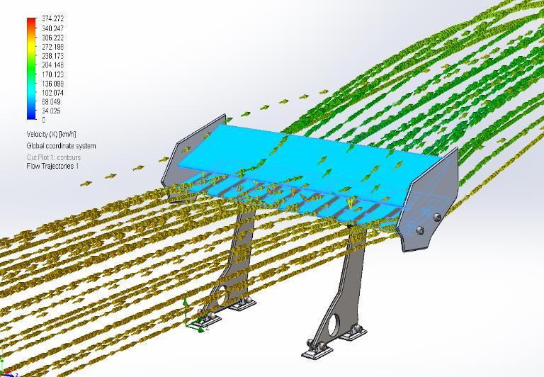
Airflow simulation insights for rear spoiler:
Therearspoilerplaysacrucialroleinmanagingtheairflow overthebackofthecar,whichisanareapronetoliftand turbulence. By incorporating the split spoiler design, the airflow was directed more effectively, reducing wake turbulence and improving pressure recovery behind the vehicle. This resulted in a stronger and more stable downforcegenerationwhileminimizingdragpenalties.The slotted lower wing helped reattach airflow that would otherwise separate, maintaining smooth flow lines and reducingthelikelihoodofchaoticvortices.
Outputs and Analysis
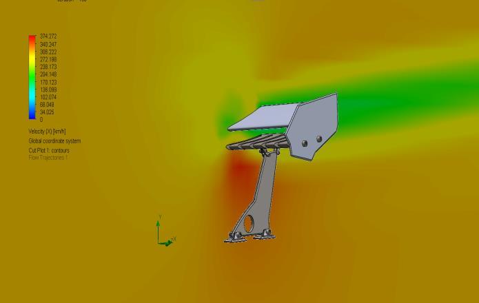
The simulation provided valuable insights into several aerodynamic factors. Pressure distribution maps revealed how the spoiler's shape managed high and low-pressure zones,contributingtothegenerationofdownforce.
The redesigned split spoiler showed a more uniform pressure distribution compared to the original design, indicating effective airflow management. Flow velocity
streamlinesvisualizedthebehaviorofairasitpassedover and beneath the spoiler. These streamlines demonstrated improved airflow reattachment in the split spoiler, particularlyduetotheslotteddesign,whichhelpedchannel andstabilizeairflowincriticalareas.Turbulenceintensity wasalsoevaluated,showingaslightincreasecomparedto thebaselinedesign,butthiswaswithinacceptablelimitsfor maintainingvehiclestability.
4. METHODOLOGY AND CALCULATIONS
Baseline Design Parameters:
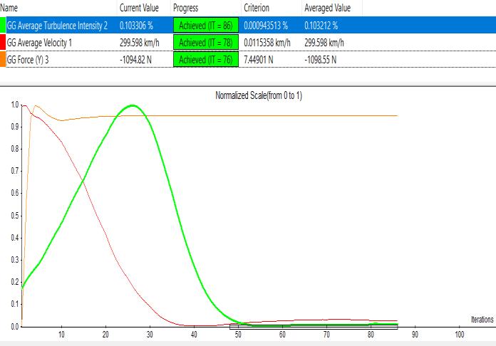
Downforce(FL ):1098.55N
Airspeed(v):300km/h(83.33m/s)
TurbulenceIntensity(TI):0.103212%
WingArea(A):0.5m²(assumed)
AirDensity(ρ):1.225kg/m³
Fromtheliftequation:
CLold=2FL/ρv2A
Substitutingvalues:
CLold=2(1098.55)/1.225(83.33)2(0.5)
=0.319
New Design Parameters:
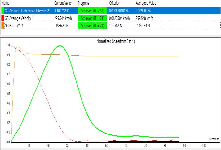
Downforce(FL ):1342.34N
TurbulenceIntensity(TI):0.109903%
Newliftcoefficient:
CLnew=2FL/ρv2A
CLnew =2(1342.34)/1.225(83.33)2(0.5)
International Research Journal of Engineering and Technology (IRJET) e-ISSN: 2395-0056
Volume: 11 Issue: 12 | Dec 2024 www.irjet.net p-ISSN: 2395-0072
=0.39
Lift-to-Drag Ratio
AdragcoefficientCD of0.034forthebaselineand0.036for thenewdesign:
L/Dold= CLold/CD
=0.319/0.034=9.38
L/Dnew= CLnew/CD
=0.390.036=10.83
Turbulence Analysis
ImpactofTurbulence
Turbulenceintensity(TI)quantifiesfluctuationsinairflow velocity,calculatedas:
TI= u′/U
Where:
u′Rootmeansquareofvelocityfluctuations
U:Meanflowvelocity
TI=Root Mean Square of Velocity Fluctuations/ Mean Flow Velocity×100
Lower turbulence intensity indicates smoother airflow, whilemoderateincreasesareacceptableifaccompaniedby significantaerodynamicbenefits.Theslotteddesignofthe split spoiler promotes flow reattachment, reducing separationzonesandwaketurbulence.Turbulenceintensity increasedmarginallyfrom0.103212%to0.109903%.This increaseiswithinacceptablelimitsformaintainingstability.
The implementation of the improved split spoiler design impacts several areas of vehicle performance beyond aerodynamics.Whiletheincreaseddownforceslightlyraises drag, leading to a minor reduction in fuel efficiency, it significantly enhances handling and stability during highspeedmaneuversbyimprovingtiretraction.Thisimproved grip allows the vehicle to maintain better control during cornering and braking, reducing stopping distances and ensuringmoreprecisehandling.Additionally,theincreased stability and braking performance contribute to overall safety, making the vehicle more responsive and reliable underdynamicdrivingconditions,particularlyincriticalor emergencyscenarios.
To evaluate the impact of the redesigned split spoiler, the BMWM4Coupewasselectedasthecasestudyvehicledueto
itsweightof1,680kganditsbaselinespoilerperformance, whichcloselyalignswiththeolderspoilerdesignusedinthis study. The original spoiler on the BMW M4 generates a downforce of 1098.55 N at a speed of 300 km/h, with a coefficientofdrag(CD)of0.34.Thesecharacteristicsmakeit asuitablecandidateforimplementingthenewsplitspoiler design,allowingforadirectcomparisonofaerodynamicand performanceimprovements.Theredesignaimstoenhance downforcewhilemaintainingmanageablelevelsofdragand turbulence, ensuring better stability and handling at high speeds.
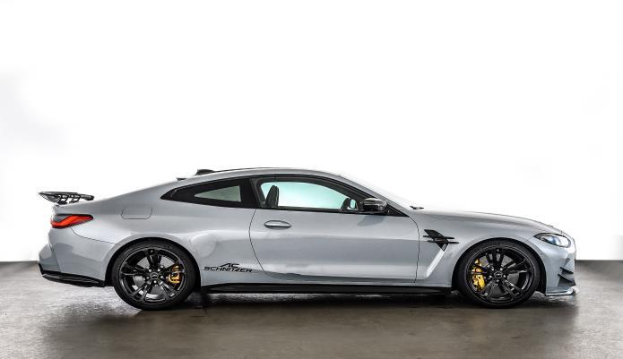
:- BMWM4coupe
(takenfrom:-https://www.acschnitzer-us.com)
Theadditionaldownforcetranslatestoimprovedtiregrip. This enhances cornering performance and braking efficiency:
Weight on Tires (New)=
Vehicle Weight+ Downforce
New Tire Load=(1680*9.81)+1342.34
=17510.34
Cornering Force:
Forcorneringfrictionforceplayvitalrole
International Research Journal of Engineering and Technology (IRJET) e-ISSN: 2395-0056
Volume: 11 Issue: 12 | Dec 2024 www.irjet.net p-ISSN: 2395-0072
Frictionalforceatthetires isproportionaltoverticalload:
Ffriction= μ*Tire Load
Assumingμ=0.9(frictioncoefficientforperformancetires):
Calculated Frictional force of BMW M4 coupe is nearly 15268N
Ffriction(new)=0.9*17510.34
=15759.3 N
Theincreaseincorneringforce(5.1%)improveshandling significantly.
Using the BMW M4 Coupe as an example, the redesigned split spoiler demonstrated significant performance improvementscomparedtoitsassumedolderspoiler.
Downforceincreasedby22.2%,risingfrom1098.55Nto 1342.34Nataspeedof300km/h,enhancingtiregripand stability.Althoughturbulenceintensitysawaslightriseof 6.5%(from0.103212%to0.109903%),itremainedwithin manageablelevels.
Additionally,thefrictionalforceonthetiresincreasedby 5.1%, from 15,268.1 N to 15,759.3 N, contributing to improvedbrakingandcorneringperformance.Theseresults highlighttheenhancedaerodynamicsandoverallhandling capabilitiesprovidedbythenewdesign.
Thesplitspoilerdesignofferssignificantimprovementsin aerodynamic performance, demonstrating an increase in downforcefrom1094.32Nintheoriginaldesignto1342.34 N at a wind speed of 300 km/h. This enhancement is achievedthroughtheintroductionofasecond,slottedwing positioned at a downward angle, which effectively moderates turbulence and ensures better airflow reattachment.
Theslightincreaseinturbulenceintensity,from0.1032% to0.109903%,isanacceptabletrade-off,asitisaccompanied by a substantial boost in vehicle stability, handling, and corneringperformance.Thisadvanceddesignhighlightshow innovative aerodynamic solutions can transform vehicle dynamicsunderhigh-speedconditions.
One of the key benefits of the split spoiler lies in its efficient airflow management. The slotted configuration reduceswaketurbulenceandenhancespressurerecovery, contributingtoabetterlift-to-dragratio.Byincreasingthelift coefficient (CL) without significantly affecting the drag coefficient(CD)thedesignprovidessuperiortractionandgrip during high-speed manoeuvres. The reduction in vortex generationaround the vehicle resultsinsmootherairflow, improving overall aerodynamic efficiency. These
improvements directly impact braking performance by shorteningstoppingdistancesandenablingmorepreciseand responsive handling, particularly in challenging driving scenarios.
Although the split spoiler delivers outstanding aerodynamicandsafetybenefits,futureresearchcanexplore furtherenhancements.Forexample,minimizingdragwhile maintaining or increasing downforce could improve fuel efficiency, making the design more practical for everyday vehicles.Refinementstotheslottedconfiguration,coupled withtheuseoflightweightmaterials,couldfurtheroptimize theperformanceandadaptabilityofthespoiler.Thisstudy emphasizesthecriticalroleofinnovativespoilerdesignsin advancingvehiclestability,safety,andefficiency,makingita valuablestepforwardinautomotiveaerodynamics.
1. Hucho,W.H.(2013).Aerodynamics of Road Vehicles (5thed.).SAEInternational.Chapter:“Fundamentals ofVehicleAerodynamics.”
2. Katz,J.(2016).Race Car Aerodynamics: Designing for Speed. BentleyPublishers. Chapter: “Spoiler and WingApplicationsinRaceCars.“
3. Anderson,J.D.(2010).FundamentalsofAerodynamics (5th ed.). McGraw-Hill Education. Chapter: “IncompressibleFlowOverAirfoils.”
4. Selig, M. S., Guglielmo, J. J., & McGranahan, B. D. (1997). "High-Lift Aerodynamics: Airfoil Design Methods." Journal of Aircraft
5. Al-Garni, A. Z., & Al-Mozaini, S. M. (2018). "Aerodynamic Analysis of a Rear Spoiler for PassengerCarsUsingCFD." Applied Sciences
6. Aghav, V., & Patil, R. (2020). "CFD Analysis of Automobile Spoiler and its Impact on Aerodynamics." International JournalofEngineering Research & Technology (IJERT).
7. Srivastava,S.,&Kumar,A.(2020)."CFDAnalysisof Rear Spoiler for Improved Vehicle Stability." International Journal of Mechanical and Production Engineering Research and Development (IJMPERD)
8. Spohrer,M.,&Gatzweiler,R.(2022)."TheImpactof DownforceonVehicleDynamics:AnAnalysisUsing AerodynamicSimulations." AutomotiveEngineering
9. Versteeg, H. K., & Malalasekera, W. (2007). An Introduction to Computational Fluid Dynamics: The Finite Volume Method.PearsonEducation.
International Research Journal of Engineering and Technology (IRJET) e-ISSN: 2395-0056
Volume: 11 Issue: 12 | Dec 2024 www.irjet.net p-ISSN: 2395-0072
10. Kim, J., & Kline, S. J. (1999). "Effects of Flow ReattachmentonAerodynamicEfficiency." Journalof Fluid Mechanics.
11. Versteeg, H. K., & Malalasekera, W. (2007). An Introduction to Computational Fluid Dynamics: The Finite Volume Method (2nded.).PearsonEducation. Chapter:“CFDApplicationsinAerodynamics.”
12. Bejan, A. (2013). Shape and Structure, from Engineering to Nature.CambridgeUniversityPress. Chapter: “Flow Optimization and Natural Aerodynamics.”
13. Kumar, R., & Kaushik, R. (2019)."Optimization of Lift-to-Drag Ratio for Automotive Aerodynamics." International Journal of Vehicle Design
14. Aghav, V., & Patil, R. (2020)."CFD Analysis of AutomobileSpoileranditsImpactonAerodynamics. “International Journal of Engineering Research & Technology (IJERT)
15. Pope, A., & Goin, K. L. (2001). High-Lift Aerodynamics.CambridgeUniversityPress.Chapter: “Airfoil and Wing Configurations for Automotive Applications.”
16. Wang, X., & Li, Z.(2019)."Numerical Simulation of FlowReattachmentinSplitSpoilerDesign." Journal of Fluid Mechanics