
International Research Journal of Engineering and Technology (IRJET) e-ISSN:2395-0056
Volume: 11 Issue: 12 | Dec 2024 www.irjet.net
p-ISSN:2395-0072

International Research Journal of Engineering and Technology (IRJET) e-ISSN:2395-0056
Volume: 11 Issue: 12 | Dec 2024 www.irjet.net
p-ISSN:2395-0072
Jilei DONG,Guanghong MIAO,Liang LI,Hongxue ZHANG
School of Mechanics and Optoelectronics Physics, Anhui University of Science and Technology, Anhui Huainan 232001,China
Abstract: The thin-walled circular tube bending and twisting combined deformation experiment is a typical representative of combined deformation experiments. Through this experiment, one can master the principles of strain gauge placement,
learn to analyze the strain components of corresponding strain gauges, and thus design bridge paths appropriately to measure the strain components generated by a certain internal force separately. This article first conducts stress analysis on the bending and twisting combined deformation of thin-walled circular pipes, in order to understand the stress state at any point on the surface of thin-walled circular pipes; Then analyze the magnitude and direction of the principal strain at the designated point of the thin-walled circular tube under three different strain flower pasting methods; Finally, the electrical measurement method is used to study the magnitude and direction of the principal stress at a specified point on the surface of a thin-walled cylinder, as well as the normal stress caused by the bending moment in the specified section, the shear stress caused by the torque, and the shear stress caused by the shear force. This technology can lay a solid practical foundation for students to engage in work related to engineering monitoring.
Keywords: Thinwalledcirculartube;Combinationdeformation;Stressanalysis;Electricalmeasurementmethod
Resistancestrainmeasurement(electricalmeasurement)technologyisanimportantandpracticaltechniqueinthefieldof mechanics.Theuseofresistancestraineffectcanconvertthemeasuredmechanicalquantitiesintoelectricalquantitiesfor testing. Mastering this technology can lay a solid practical foundation for students to engage in engineering monitoring work[1].
In engineering practice, components often undergo two or more basic deformations under load, namely combined deformation [2]. The experiment of thin-walled cylinder under combined bending and twisting deformation is a typical representative.Thedeterminationofinternalforcesduringthecombinedbendingandtwistingdeformationofthin-walled cylinders is one of the teaching experiments in the course of materials mechanics, and it also has practical value in engineering.Throughthisexperiment,onecanmastertheprincipleofarrangingstraingauges,learntoanalyzethestrain componentsofstraingauges,andbeabletodesignbridgesappropriatelytomeasurethestraincomponentsgeneratedby certaininternalforcesseparately[3].
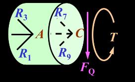
Theexperimentalapparatusforcombinedbendingandtwistingdeformationandthecross-sectionofthethin-walled circulartubeareshowninFigure1.Oneendofthecirculartubeisafixedend,andtheotherendisfixedlyconnectedtoa
steelcrankarmwithalengthof a .Thecirculartubeundergoesacombinationofbendingandtwistingdeformationunder theactionofconcentratedforce F ,andthedistancefromthetestedsectionI-ItothefreeendisL.Accordingtothestress statetheoryanalysis,allpointsonthesurfaceofthethin-walledcylinderareinaplanestressstate[4].
International Research Journal of Engineering and Technology (IRJET) e-ISSN:
Volume: 11 Issue: 12 | Dec 2024 www.irjet.net
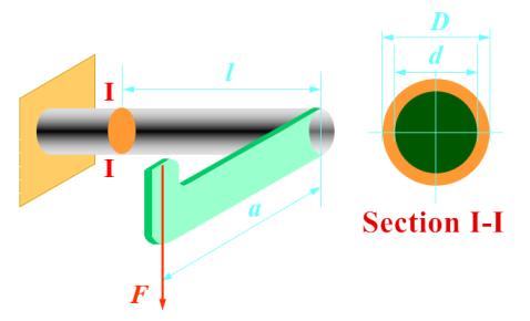
Fig.1: Experimentalapparatusandcross-sectionalschematicdiagramforcombinedbendingandtwistingdeformation
Takeanypointonthesurfaceofthethin-walledcirculartubeforstressanalysis,andtheplanestressstateofanypoint isshowninFigure2.FromFigure2,itcanbeseenthatthesurfaceofthecomponentisinaplanestressstate.Toobtainthe magnitude and direction of the principal stress of the unit cell in the plane stress state, it is necessary to know the magnitude and direction of the stress in the two perpendicular directions of the unit cell, as well as the magnitude and directionoftheshearstress[5].
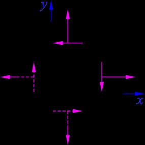
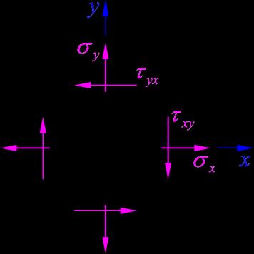
Fig.2: Stressanalysisunderplanestressstate
AccordingtoHooke'sLaw[6],itcanbeconcludedthat:
Amongthem: 1 isthemaximumprincipalstress, 2 istheminimumprincipalstress, 1 isthelinestraininthe direction of the maximum principal stress ( 1 ), 2 is the line strain in the direction of the minimum principal stress ( 2 ), E istheelasticmodulus,and isPoisson'sratio.
Themagnitudeoftheprincipalstressatanypointcanbeobtainedfromequation(1)asfollows:
International Research Journal of Engineering and Technology (IRJET) e-ISSN:2395-0056
Fortheconvenienceofexpressingstrainindifferentdirections,acoordinatesystemissetforthemeasuringpoint,and thestraincomponentsatthemeasuringpointaredefinedas x , y ,and xy .Theanglebetween the measuring point andtheX-axisisdefinedasthemaindirectioninthe direction,andtheangle isdefinedaspositivewhenrotated counterclockwise.Thereare[7]:
Aftertransformingthetrigonometricrelationship,weobtain:
From equation (4), a strain circle can be obtained as shown in Figure 3, with on the x-axis and /2 on the y-axis[8].Thisstraincirclecanrepresentthevariationofstrainindifferentdirectionsatapointunderplanestressstate.
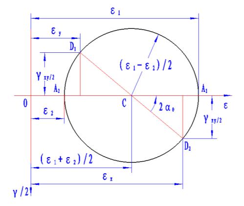
AccordingtothestraincircleundertheplanestressstateshowninFigure3,itcanbeconcludedthat: (
Volume: 11 Issue: 12 | Dec 2024 www.irjet.net p-ISSN:2395-0072 xy cannot be directly measured. The unique can be directly measured, but y and x
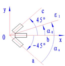
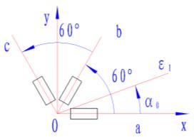
In actual measurement, circlecanbedeterminedbythreepoints,andaslongasthelinestraininanythreedirectionsisknown,theuniquestrain circlecanbedetermined.Inactualmeasurement,whenthedirectionoftheprincipalstressateachpointisunknown,itcan bedeterminedbyarrangingarightanglestrainflowerverticallypastedatthemeasuredpoint,arightanglestraininclined 45degreepastedmethod,oranequiangularstrainflowerpastedmethod[9].
According to equations (4) and (5), three strain flower pasting methods can be obtained, and the magnitude and directionoftheprincipalstrainareshowninTable1.
Table 1:Threetypesofstrainflowerpastingmethodsandthemagnitudeanddirectionoftheprincipalstrain
Paste method
Schematic diagram of strain flower pasting method Mainstrainmagnitudeanddirection
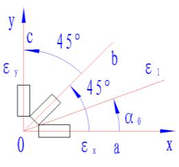
BysubstitutingtheprincipalstrainvaluesofthethreestraingaugesinTable1into equation(2),theprincipalstress valuescorrespondingtothethreestraingaugescanbeobtained.
The magnitude of the principal stress for the vertical pasting method of the right angle strain flower and the 45
inclinedpastingmethodoftherightanglestrainfloweris:
Theprincipalstressmagnitudeoftheadhesivemethodforequiangularstrainflowers
International Research Journal of Engineering and Technology (IRJET) e-ISSN:2395-0056
Volume: 11 Issue: 12 | Dec 2024 www.irjet.net p-ISSN:2395-0072
Taking the method of pasting strain gauges at a 45 degree angle with a right angle strain inclination as an example, this study investigates the magnitude and direction of the principal stress at a specified point on the surface of a thin-walled cylinder, as well as the normal stress caused by the bending moment within the specified section, the shear stresscausedbythetorque,andtheshearstresscausedbytheshearforce.
Selectfourpoints, ABCD 、 、 、 ,onthetop,bottom,front,andbackofthe I-I sectionofthethin-walledcylinder shown in Figure 1. The positions of the four points are shown in Figure 4, and a set of strain flowers with a right angle straininclinationof45degreesarepastedatthepoints ABCD 、 、 、 ,asshowninFigure5.
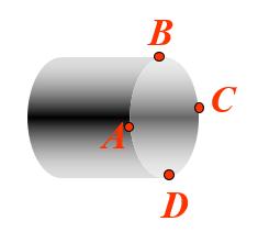
Fig.4: SurfacetestpointsonsectionI-I
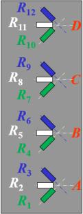
Fig.5:Schematicdiagramofpastingstrain gaugesattestpoints
4.1 Testing method for magnitude and direction of principal stresses at points ABCD 、 、 、
4.1.1Theoreticalanalysisofthemagnitudeanddirectionofprincipalstressesatpoints ABCD 、 、 、
Accordingtotheknowledgeofmaterial mechanics[10],therearethreetypesofinternalforces:bendingmomentM, torqueT,andshearforceQonsectionI-I.Therefore,thestressesoftheunitcellsatpointsa/b/c/donsectionI-Iarecaused bytheseinternalforces.
Points BD 、 :Point B experiencestensilestress,whilepoint D experiencescompressivestress.Theshearstress caused by bending is zero, and the normal stress caused by bending and the shear stress caused by torsion constitute a biaxialstressstate,asshowninFigure6.
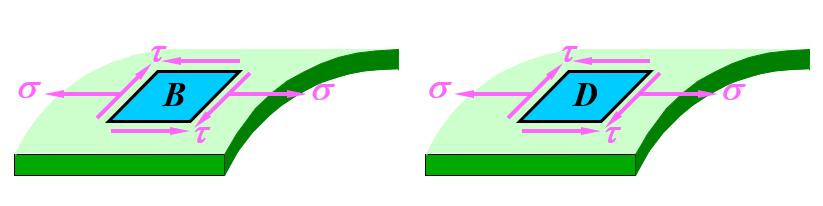
Fig.6:StressstateanalysisofpointsBandD
Accordingtotheknowledgeofmaterialmechanics,thenormalstresscausedbybendingmomentMatpointsBandD andtheshearstresscausedbytorsionTatpointsBandDarerespectively:
International Research Journal of Engineering and Technology (IRJET) e-ISSN:2395-0056
Volume: 11 Issue: 12 | Dec 2024 www.irjet.net
Among them, z W is the bending section modulus of the circular tube; tW is the torsional section modulus of the circulartube; = dD 。
AccordingtoFigure6,thestresscomponentsatpoints BD 、 areasfollows:
Themagnitudeandprincipaldirectionofthenormalstressatpoints BD 、 are:
Amongthem, istheanglebetweenthemainstressandtheaxisofthecirculartube.
TwopointsAandC:BothpointsAandCareinastateofpureshearstress,andbothpointsareontheneutrallayer,so theywillnotcauseprincipalstress.However,torqueandshearforcerespectivelycauseshearstress,asshowninFigure7.
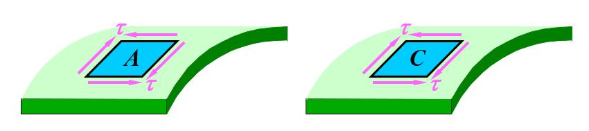
7:Stressstateanalysisofpoints AC 、
Accordingtotheknowledgeofmaterialmechanics,theshearstresscausedbytheshearforceQatpointsBandDis:
Amongthem,
AccordingtoFigure7,thestresscomponentatpointAis:
ThestresscomponentatpointCis:
Themagnitudeanddirectionoftheprincipalstressatpoints AC 、 are:
International Research Journal of Engineering and Technology (IRJET) e-ISSN:
Volume: 11 Issue: 12 | Dec 2024 www.irjet.net
4.1.2Testingmethodformagnitudeanddirectionofprincipalstressesatpoints ABCD 、 、 、
Connect strain gauges 112RR at four points ABCD 、 、 、 on section I-I using the half bridge common externalcompensationwiringmethodtothestraingauge,andmeasurethebridgeasshowninFigure8.
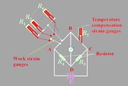
Fig 8: 112RR HalfBridgeCommonTemperatureCompensationWiringMethod
Afterloadingthelevels,the strainsof points ABCD 、 、 、 can bemeasured separately. Bysubstituting thestrain i of points ABCD 、 、 、 into the following formulas, the magnitude and direction of the principal stress at each pointcanbecalculated.
4.2 Testing method for normal stress caused by bending moment M
ThetheoreticalvalueofthenormalstresscausedbybendingMatpointsBandDisshowninequation(8).
Measure the normal stress caused by bending moment M by connecting strain gauges 5R and 11R at ° 0 on the topandbottom(BD 、 )ofthecylinderusingthehalfbridgeconnectionmethod,asshowninFigure9.
International Research Journal of Engineering and Technology (IRJET) e-ISSN:2395-0056
Volume: 11 Issue: 12 | Dec 2024 www.irjet.net p-ISSN:2395-0072
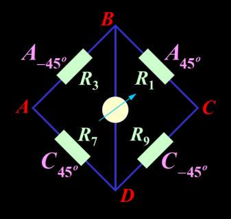
Fig.9: Wiringdiagramformeasuringnormalstresscausedbybendingmoment
According to the knowledge of electrical measurement method, the relationship between strain degree and positive straincausedbybendingmomentwhenwiringaccordingtoFigure9is: 2 ds M
(17)
Amongthem: ds isthemeasuredstrainreading; M isthepositivestrainvaluecausedbybendingmoment.
AccordingtoHooke'sLaw,thenormalstresscausedbybendingmomentis:
ds MM E E
18)
Amongthem, M isthenormalstresscausedbybendingmoment.
4.3 Testing method for shear stress caused by torque T
ThetheoreticalvalueofthenormalstresscausedbytorqueTatpointsBandDisshowninequation(9).
Measure the shear stress caused by torque T by connecting four strain gauges 1R , 3R , 7R , and 9R at two points -45°and45°infrontandbehindthecylinder(A,C)totheentirebridgeline,asshowninFigure10.
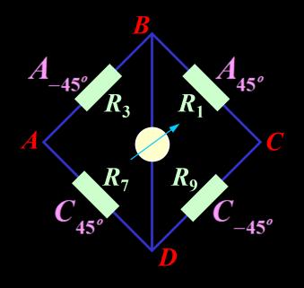
Fig.10:Wiringdiagramofshearstresscausedbytorquemeasurement
According to the knowledge of electrical measurement method, the relationship between strain degree and strain causedbytorquewhenwiringaccordingtoFigure10is:
4 dsT (19)
International Research Journal of Engineering and Technology (IRJET) e-ISSN:2395-0056 Volume: 11 Issue: 12 | Dec 2024 www.irjet.net p-ISSN:2395-0072
Amongthem, T isthestrainvaluecausedbytorque T
Theshearstraincausedbytorqueis: 2 2 ds TT
(20)
Amongthem, T istheshearstraincausedbytorque T .
AccordingtoHooke'slawofshear,theshearstresscausedbytorqueis:
(21)
Amongthem: T istheshearstresscausedbytorque T ; G istheshearelasticmodulusofathin-walledcylinder.
4.4 Testing method for shear stress caused by shear force Q
Thetheoreticalvalueofshearstresscausedbyshearforce Q atpointsBandDisshowninequation(12).
Theshearstresscausedbytheshear force Q ismeasuredbyconnectingfourstraingauges 1R , 3R , 7R ,and 9R at-45°and45°infrontandbehindthecylinder(A,C)totheentirebridgeline,asshowninFigure11.
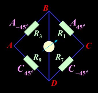
Fig.11: Wiringdiagramofshearstresscausedbyshearforcemeasurement
According to the knowledge of electrical measurement method, the relationship between the strain degree and the straincausedbyshearforcewhenwiringaccordingtoFigure11is: 4 dsQ
(22)
Amongthem, Q isthestrainvaluecausedbyshearforce.
Theshearstraincausedbyshearforceis: 2 2 ds
(23)
Amongthem, Q istheshearstraincausedbyshearforce.
AccordingtoHooke'slawofshear,theshearstresscausedbyshearforceis:
International Research Journal of Engineering and Technology (IRJET) e-ISSN:2395-0056
Volume: 11 Issue: 12 | Dec 2024 www.irjet.net p-ISSN:2395-0072
Amongthem, Q istheshearstresscausedbyshearforce.
This article first conducts stress analysis on the combined deformation of bending and twisting of thin-walled circular pipes to understand the stress state at any point on the surface of the thin-walled circular pipe; Then analyze the magnitude and direction of the principal strain at the designated point of the thin-walled circular tube under three different strain flower pasting methods; Finally, the electrical measurement method is used to study the magnitude and direction of the principal stress at a specified point on the surface of a thin-walled cylinder, as well as the normal stress caused by bending moment, shear stress caused by torque, and shear stress caused by shear force within a specified section when the thin-walled cylinder undergoes combined bending and twisting deformation. The above research not onlyprovidesameasurementmethodforseparatelymeasuringthestraincomponentgeneratedbyacertaininternalforce incompositedeformation,butalsolaysasolidpracticalfoundationforstudentstoengageinworkrelatedtoengineering monitoring.
[1] H Zheng, J Mo Extended teaching of strain electrical measurement technology based on scientific research achievements MechanicsandPractice,2016,38(3):324-327
[2] F Zhu, P Bai, Lei D, et al. Discussion on the measurement scheme of bending shear stress in bending torsion combinationexperiment ExperimentalTechnologyandManagement,2022,39(4):138-144
[3] H Li, Y Liu, M Wang, et al. Improvement of cylinder bending and twisting combination experiment Experimental TechnologyandManagement,2017,24(11):43-45
[4] J Wu, M Yang, L Zhao, et al. Teaching of Bending Twist Combination Experiment in Mechanics Experiment China MetallurgicalEducation,2019(6):65-68
[5]RZhang,YLu.Experimentalstressanalysis.MechanicalIndustryPress,1983.
[6]XSun,XFang,LGuan MechanicsofMaterials(I) HigherEducationPress,2002
[7] Y Kang, Y Cheng, P Xia, et al. Reform of Materials Mechanics Experimental Teaching under the Background of New Engineering EducationandTeachingForum2022(18):73-76
[8]LSun,JWang,MechanicsExperiment.Nanjing:HehaiUniversityPress,2019.
[9]JHuang,RTao,ZJiang,etal.Theinfluenceofselectingdifferentstraingaugesontheresultsofprincipalstresstesting Laboratoryresearchandexploration,2016,35(7):32-36.
[10]HLiu MechanicsofMaterials(I) HigherEducationPress,2004