
International Research Journal of Engineering and Technology (IRJET) e-ISSN: 2395-0056
Volume: 11 Issue: 12 | Dec 2024 www.irjet.net p-ISSN: 2395-0072

International Research Journal of Engineering and Technology (IRJET) e-ISSN: 2395-0056
Volume: 11 Issue: 12 | Dec 2024 www.irjet.net p-ISSN: 2395-0072
Desai Abhishek Annasaheb1 , Dr. Chethan K2
1P.G Student, Department of Civil Engineering, U.V.C.E, Bangalore University, Bengaluru
2Associate Professor, Department of Civil Engineering, U.V.C.E, Bangalore University, Bengaluru.
Abstract - Steel bracingsystems play a key role in ensuring the stability of high-rise buildings by effectively resisting lateral forces induced by wind, seismic activity and other dynamic loads. Various types ofsteel bracingsystemsareused in high-rise buildings focusing on their design considerations, performance under different loading conditions and the impact onoverallbuildingstability. The objectiveistoprovide a comprehensive understanding of bracing systems, highlighting their importance in modern high-rise constructionandofferinginsights into theselectionofoptimal bracing solutions to achieve a balance between safety, cost effectiveness and sustainability.
In this study, RC Frame of G+15 stories is considered with different steel braces along with hybridbracingsystemforthe Finite Element Analysis.Theperformanceofbuildingisstudied in terms of Modal, Equivalent Static and Response Spectrum analysis. Time Period, Base shear, Displacement and Storey Drift results are obtained, tabulated and conclusions are drawn
KeyWords: Cross-bracing,V-bracing,InvertedV-bracing, diagonal braces, Time Period, Base Shear, Storey DisplacementandStoreyDrift.
Steel bracings are a crucial component in the structural design of high-rise buildings, providing essential stability and resistance against lateral forces such as wind and earthquakes.Theseforcescancausesignificantdisplacement and deformation in a structure, and steel bracing systems aredesignedto minimize thisby enhancing the building's rigidityandstrength.Theuseofsteelbracingsinhigh-rise constructionoffersseveraladvantages,includingimproved load-bearing capacity, cost-effectiveness, and ease of installation.Steel’shighstrength-to-weightratiomakesitan idealmaterialforsupportinglargeloadswhilemaintaininga relativelylightstructure.Furthermore,steelbracingsystems can be tailored to meet the specific demands of different building designs, offering flexibility in layout and appearance. Bracing systems can take various forms, including diagonal braces, cross-bracing, and momentresistingframes, eachofferinguniquebenefitsinterms of performanceandaestheticintegration.Thechoiceofbracing typedependsonfactorssuchastheheightofthebuilding,its location,andthetypeofloadsitisexpectedto encounter.
Overall,incorporatingsteelbracingsinhigh-risebuildingsis vital forensuringsafety,stability,andstructural integrity, making it a fundamental consideration for engineers and architects involved in the design and construction of tall structures.
Thesteelbracesareusuallyplacedinverticallyaligned spans. This system allows to obtaining a great increase of stiffnesswithaminimaladdedweight.Concentricbracings increasethelateralstiffnessoftheframethusincreasesthe natural frequency and also usually decreases the lateral storey drift. Concentric bracing are designed to be in pure axialcompressionortensionwhenlateralloadsareapplied. Whenwindorseismicforcespushorpullonthebuilding,the braces either compress or stretch, transferring the load throughthediagonalbracestothecolumnsandbeams,which in turn transfer the forces to the foundation. This system operatesbasedontheconceptofaxialloadtransfer,which makesiteffectiveinresistinglateralforceswithoutinducing bendingorsignificantdeformationintheframe.
The eccentricity in the bracing system introduces a combinationofbothshearandbendingforces,allowingthe braces to resist larger lateral loads more efficiently. The bracesworktoabsorblateralforcesby"deforming"atthe connectionpoint,oftenthroughaplastichingemechanism where the braces or connections yield, dissipating energy from seismic forces. The eccentric nature of the bracing allowsforamoreflexiblesystem,whichcandissipateenergy moreeffectivelyduringseismicevents,reducingtheamount of force transmitted to the overall structure. The energy dissipationthroughtheyieldingofbracesorjointsmakesthe systemespeciallyusefulinearthquake-resistantdesigns.
1. ToevaluatetheDynamicResponseofaTypicalRC BareFramewithvariousbracingsystemssubjected toseismicloads.Bracingsystemusedinthisstudy areX,V,InvertedVandDiagonalBracings.
2. ToevaluatetheDynamicResponseofaTypicalRC BareFramewithcombinationofthebracingsystems calledas“HybridBracingSystem” .
International Research Journal of Engineering and Technology (IRJET) e-ISSN: 2395-0056
Volume: 11 Issue: 12 | Dec 2024 www.irjet.net p-ISSN: 2395-0072
3. FiniteElementSoftwareisusedfortheanalysisofFE modelsdevelopedusingdetailsfromliterature.
4. FE Analysis involving Modal Analysis, Equivalent StaticAnalysisandResponseSpectrumAnalysisto beperformedonallthemodels.
5. Results such as Base Shear, Time Period, Lateral DisplacementandStoreyDriftareobtained.
6. ToidentifythesuitableHybridbracingsystemfor resistingtheseismicloadefficiently.
1. Detailed literature review is carried out on the seismic response of reinforced concrete structure withdifferenttypesofbracingandcombinations.
2. A typical RC Frame G+15 storey structure is consideredforthestudy.
3. ThetypesofbracingsystemconsideredareX,V,IV and D the combinations of the bracings called as “HybridBracingSystem”
4. TheHybridbracingssystemconsideredforthestudy are as follows X,XV,XIV,XD,V,VX,VIV,VD,IV,IVX,IVV,IVD,D,DX,DVand DIV.
5. Eachbracingsystemareplacedinalternatestorey levelinatypicalRFstructure.
6. FE Analysis involves Modal, Equivalent Static and Response Spectrum analysis are performed on a TypicalRFG+15Storeystructurewithbracingand thecombinationsofbracingsystemtoobtainTime period,Baseshear,StoreydisplacementandStorey drift.
Adetailedsummaryofthevariousparametersdefiningthe Regular frame (RF) with conventional bracing system and hybridbracingsystemmodelsarepresented.
The methodology involved in computing some of these parametersisexplainedandimportantfeatureofthecurrent provisions relating to earthquake resisting design of reinforced concrete lateral forces resisting system are presented
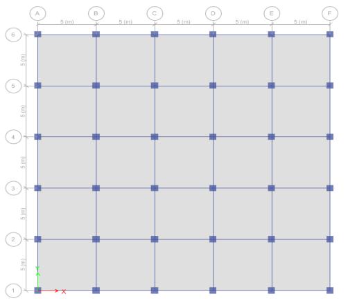
The present study adopts structural 3D models with conventional bracing system and hybrid bracing system models.Theseismicresponsesofthesebracedmodelshave been compared with that of the Regular frame building model.Thebaseplansizehasbeenkeptas25mx25m.
Table -1:DetailsforModelling
Description Data
Numberofstoreys G+15
SeismicZone V
SeismicZoneFactor(Z) 0.36
ImportanceFactor(I) 1.5
ResponseReductionFactor(R) 5.0
TypeofFrame
BuildingWithOrdinary BracedFrame(OBF) HavingConcentricBraces
DampingRatio 5%
SoilType
MediumSoil(TypeII)
BayWidth 5m
ColumnSize 600x600
BeamSize 300x450
ThicknessofSlab 150mm
FloorFinishLoad 1.5kN/m²
LiveLoad 3kN/m²
FloortoFloorHeight 3.0m
TotalHeightofStructure 48m
GradeofConcrete( ) M30
GradeofStructuralSteel( ) Fe250
GradeofReinforcingSteel( ) Fe500
LoadCombination
International Research Journal of Engineering and Technology (IRJET) e-ISSN: 2395-0056
Volume: 11 Issue: 12 | Dec 2024 www.irjet.net p-ISSN: 2395-0072
Table -2:Nomenclatureanddescriptionofthemodel G+15storey.
Details Nomenclature
RegularFrame RF
RF+X-Bracing X
RF+V-Bracing V
RF+InvertedV-Bracing IV
RF+DiagonalBracing D
RF+X-BracingandV-Bracing XV
RF+X-BracingandIV-Bracing XIV
RF+X-BracingandD-Bracing XD
RF+V-BracingandX-Bracing VX
RF+V-BracingandIV-Bracing VIV
RF+V-BracingandD-Bracing VD
RF+IV-BracingandX-Bracing IVX
RF+IV-BracingandV-Bracing IVV
RF+IV-BracingandD-Bracing IVD
RF+D-BracingandX-Bracing DX
RF+D-BracingandV-Bracing DV
RF+D-BracingandIV-Bracing DIV
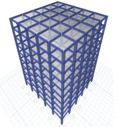
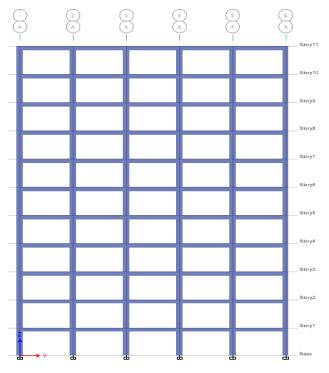
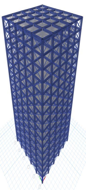
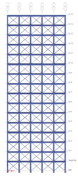
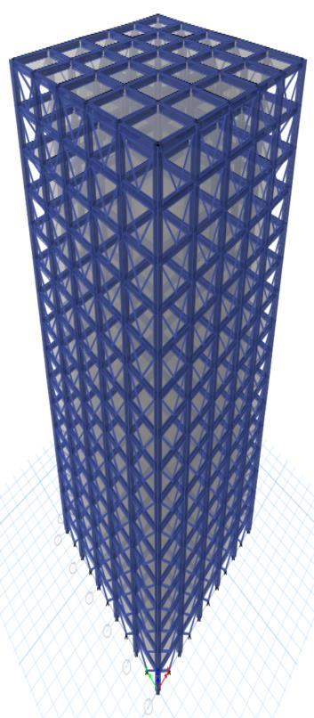
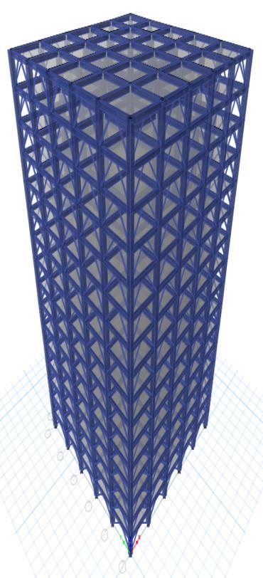
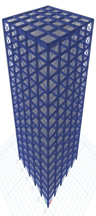
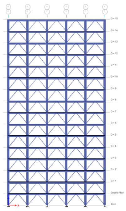
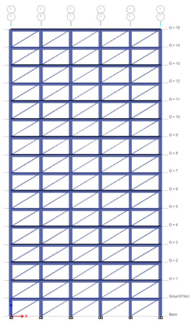
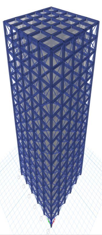
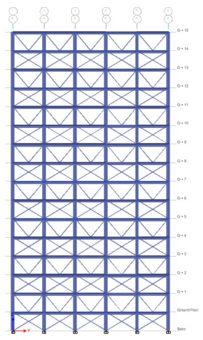
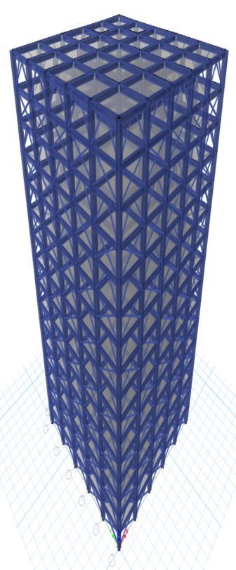
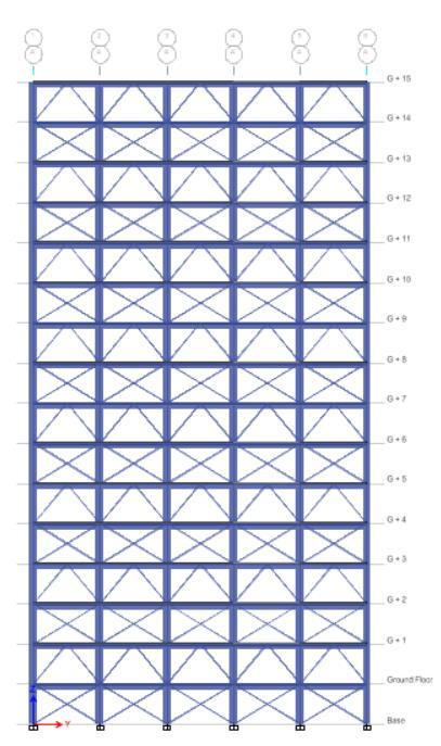
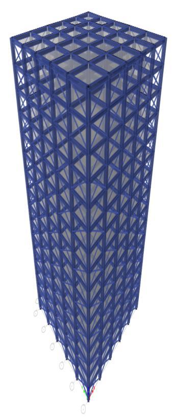
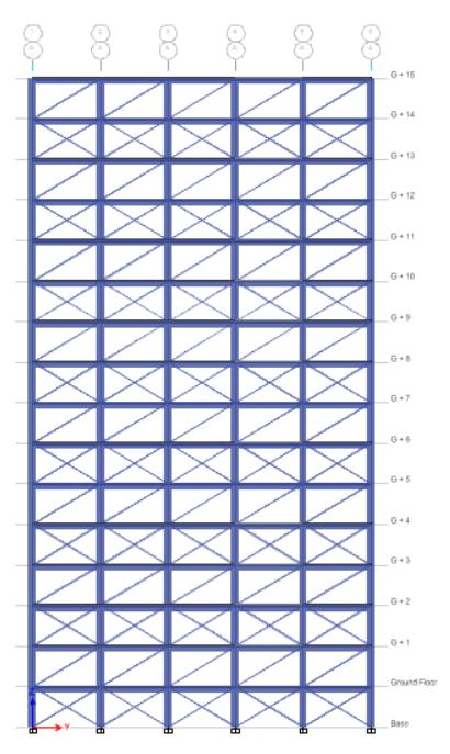
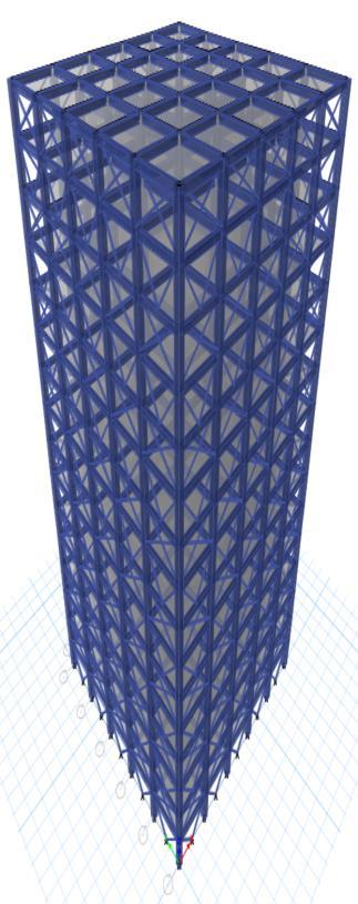
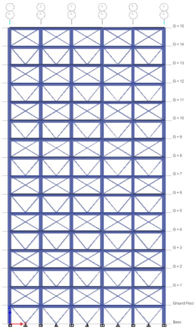
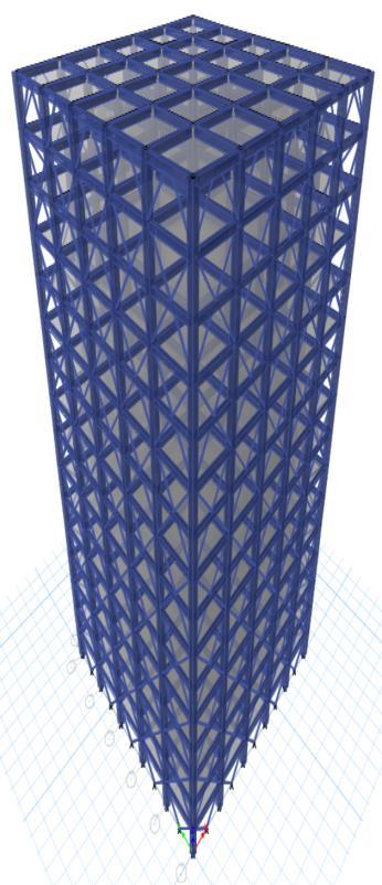
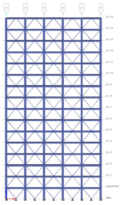
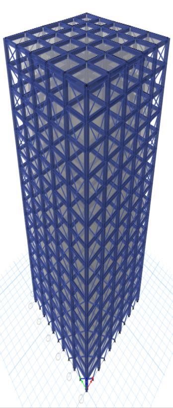
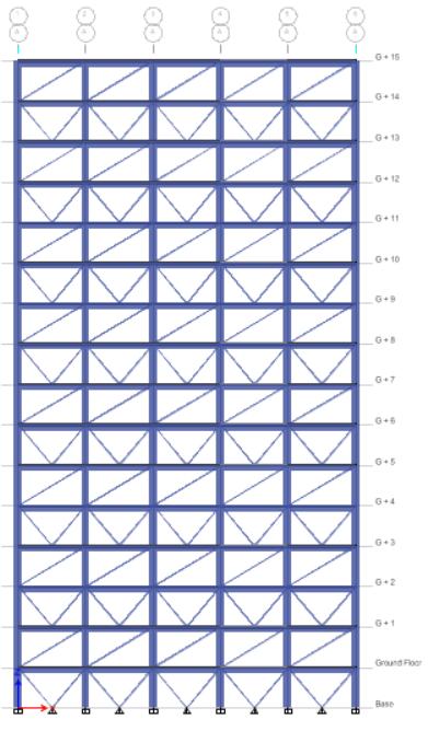
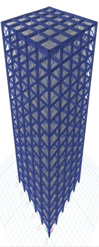
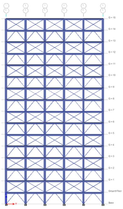
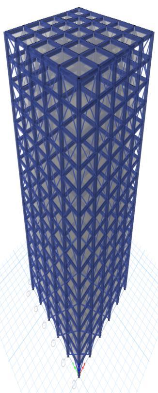
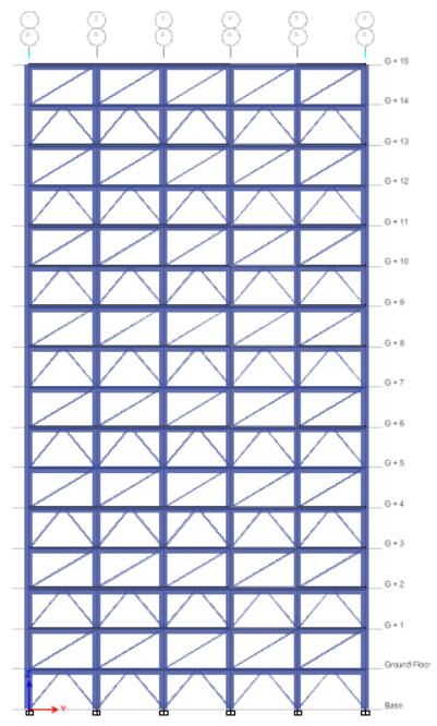
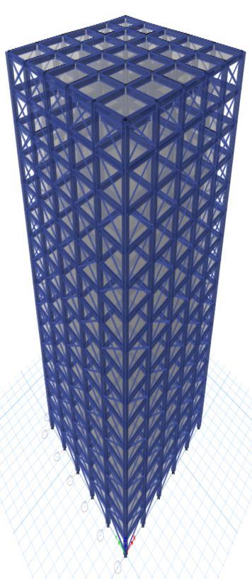
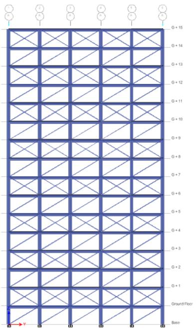
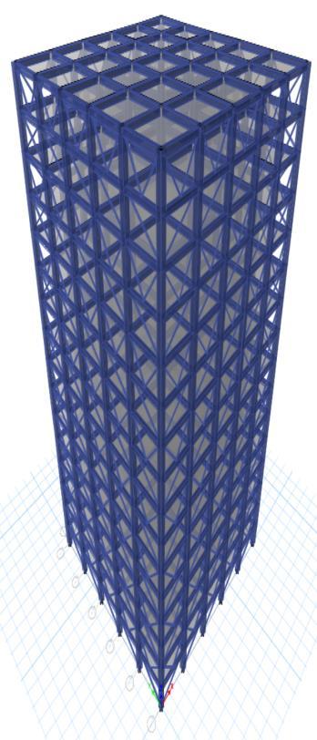
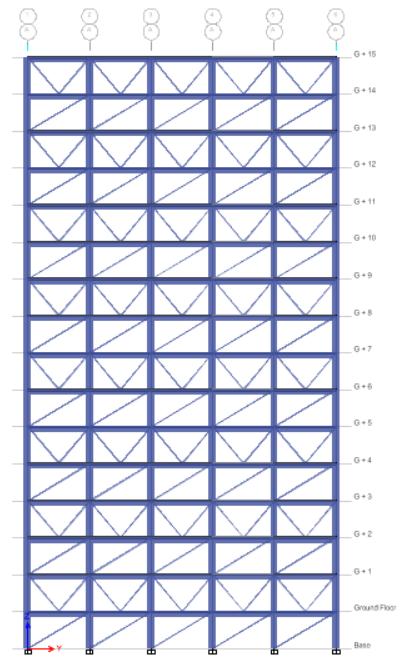
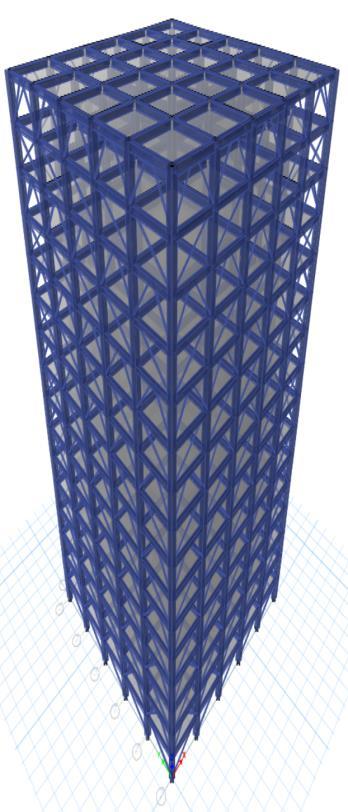
Plan, 3D and Elevation of Regular Bare Frame Structure modelcreatedinsoftwareasshowninfig1,2and3below.
International Research Journal of Engineering and Technology (IRJET) e-ISSN: 2395-0056
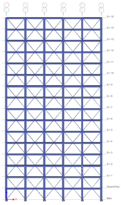
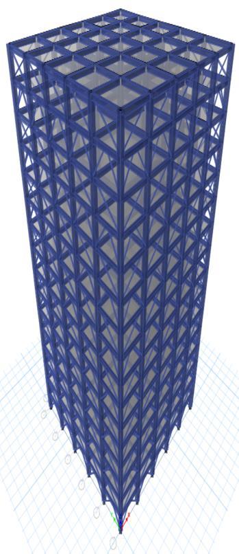
a) 3D & Elevation of RF with X Bracing
b) 3D & Elevation of RF with V Bracing
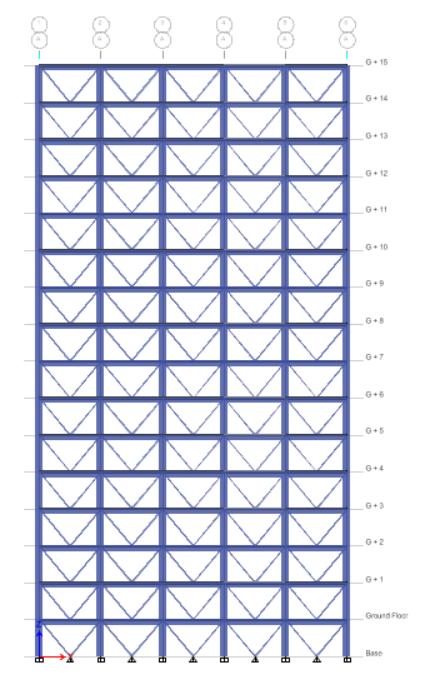
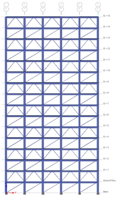
c) 3D & Elevation of RF with IV Bracing
d) 3D & Elevation of RF with D Bracing
Volume: 11 Issue: 12 | Dec 2024 www.irjet.net p-ISSN: 2395-0072 ©
International Research Journal of Engineering and Technology (IRJET) e-ISSN: 2395-0056
Volume: 11 Issue: 12 | Dec 2024 www.irjet.net p-ISSN: 2395-0072
e) 3D & Elevation of RF with XV Bracing
3D & Elevation of RF with XIV Bracing
g) 3D & Elevation of RF with XD Bracing
3D & Elevation of RF with VX Bracing
International Research Journal of Engineering and Technology (IRJET) e-ISSN: 2395-0056
Volume: 11 Issue: 12 | Dec 2024 www.irjet.net p-ISSN: 2395-0072
i) 3D & Elevation of RF with VIV Bracing
3D & Elevation of RF with VD Bracing
k) 3D & Elevation of RF with IVX Bracing
l) 3D & Elevation of RF with IVV Bracing
International Research Journal of Engineering and Technology (IRJET) e-ISSN: 2395-0056
Volume: 11 Issue: 12 | Dec 2024 www.irjet.net p-ISSN: 2395-0072
m) 3D & Elevation of RF with IVD Bracing
n) 3D & Elevation of RF with DX Bracing
o) 3D & Elevation of RF with DV Bracing
p) 3D & Elevation of RF with DIV Bracing
International Research Journal of Engineering and Technology (IRJET) e-ISSN: 2395-0056
Volume: 11 Issue: 12 | Dec 2024 www.irjet.net p-ISSN: 2395-0072
FiniteElementAnalysis(FEA)isacomputerizedmethodfor predicting how structures will behave under different conditions.Inthecontextofbuildingdesign,FEAcanbeused to simulate the structural behavior of a building, and to optimize its design to ensure it is safe, stable, and costeffective. FEA works by dividing a complex structure into smaller,simplerparts,calledfiniteelements.Bysimulating the behavior of each element individually. The process of dividingacontinuousdomain(likeastructureorobject)into smallersubdomains,or"elements".
FEA can be particularly useful in identifying potential weaknesses or failure points in a building design before construction begins. By simulating different loads and stressesonthebuilding,FEAcanpredicthowthestructure willbehaveunderdifferentconditions,andhelpengineers and architects make informed decisions about the design andmaterialsused.FEAisanumericalmethodusedtosolve complexengineeringproblems,particularlythoseinvolving structures,mechanicalcomponents,orsystems.Itiswidely used in fields like civil, mechanical, aerospace, and automotiveengineering,aswellasinmaterialscience.
Responsespectrumanalysisofstructureiscarriedoutfor theseismiczoneV,asperIS1893-2016,usingtheresponse spectrumgenerated.Baseshear,Displacement,Inter-storey drift are obtained for all the models are discussed in this section.
Aresponsespectrumisessentiallyarepresentationshowing thepeakorsteady-stateresponse(displacement,velocity,or acceleration) of a sequence of oscillators with varying natural frequencies that are all moved by the same base vibrationorshock.
CROSS SECTIONAL PROPERTIES AND MATERIAL CONSTANTS
The cross-sectional properties and material constants consideredforthestudyareshowninTable3.
Table -3:CrossSectionalPropertiesandMaterial Constants
Characteristicstrengthofsteel 250MPa
Modulusofelasticityofsteel 21000MPa
Densityofsteel 77kN/m3
Poisson’sratioforsteel 0.3
Characteristicstrengthofconcrete 30MPa
Modulusofelasticityofconcrete 27386.13MPa
Densityofconcrete 25kN/m3
Poisson’sratioforconcrete 0.2
Threetypesofloadsareasfollows.
1.Deadload
2.Liveload/Imposedload
3.Earthquakeload(inXandYdirection)
Table -4:SeismicCoefficients
Zone V
ZoneFactor 0.36(Table3ofIS:1893:2016)
ImportanceFactor(I) 1.5(Table8ofIS:1893:2016)
PercentageofLiveLoad Reduction 25%(Table8ofIS:1893:2016)
ResponseReduction Factor(R) 5.0(Table9ofIS:1893:2016)
SoilType TypeII(MediumorStiffsoil)
Zone V
ZoneFactor 0.36(Table3ofIS:1893:2016)
Timeperiod(T) Programcalculated
Thefundamentaltimeperiodforallmodelsisobtainedfrom themodalanalysis,whichcalculatesthetimeperiodonthe basisofmassandstiffnessofthestructure.IS1893(PartI): 2016givestheempiricalformulaforcalculatingthenatural timeperiodwithoutmasonryinfill.i.e,
Ta=0.075h0.75
Wherehisthetotalheightofthebuilding.
Fundamental time period calculated by modal analysis resultsaretabulatedinTable5andthegraphshowingtime periodversusmodelsareshowninFig4.
International Research Journal of Engineering and Technology (IRJET) e-ISSN: 2395-0056
Table 5: Timeperiod(sec)
Models IS 1893(PART 1)2016
(sec)
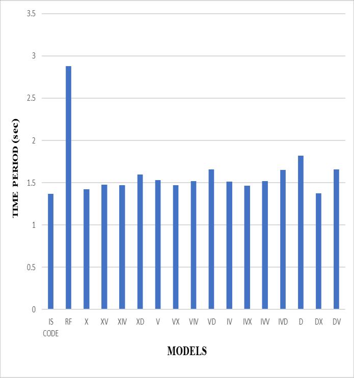
Fig 4. Time period (sec)
9.2 SCALE FACTOR
Scale factor is defined as the ratio of static base shear to dynamicbaseshear,theratiothisobtainedisusedinfurther
partofdynamicanalysisandshowninTable6and7andthe graph showing corrected base shear versus models are showninFig5.
ScaleFactor=

Volume: 11 Issue: 12 | Dec 2024 www.irjet.net p-ISSN: 2395-0072 © 2024, IRJET | Impact Factor value: 8.315 |
Were,g=Accelerationduetogravity(9810mm/ )
I=Importancefactor(1.5) R=Reductionfactor(5)


Table -6:ScaleFactor
Table -7:CorrectedDynamicBaseShear(kN)
International Research Journal of Engineering and Technology (IRJET) e-ISSN: 2395-0056
Volume: 11 Issue: 12 | Dec 2024 www.irjet.net
2395-0072
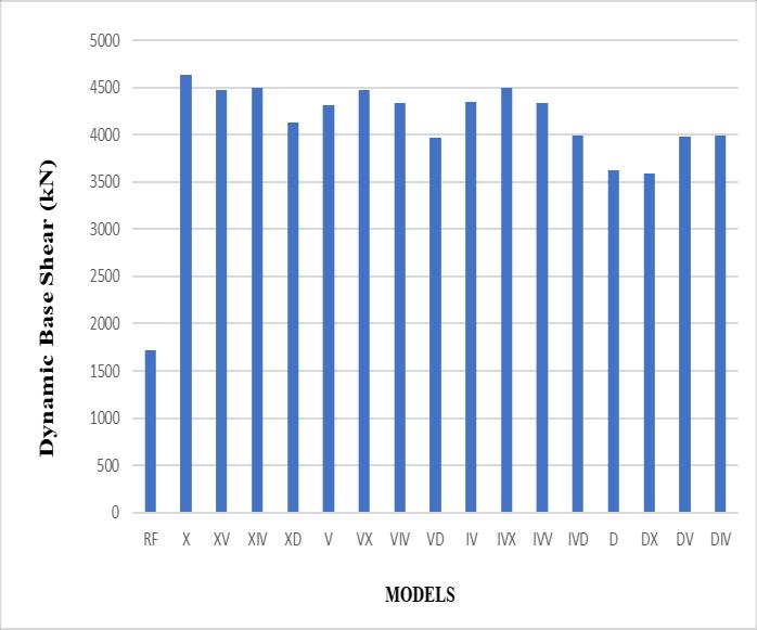
Fig 5 Corrected Dynamic Base Shear (kN)
9.3 STOREY DISPLACEMENT
ThestoreydisplacementresultsofG+15modelsareshown in Table 8, 9, 10 and 11. The plot of displacement versus storeyforRFandConventionalbracingsystemandHybrid bracingsystemmodelsareshowninFig6.
Table -8:StoreyDisplacement(mm)forHybridXBracings
Table -9:StoreyDisplacement(mm)forHybridVBracings
International Research Journal of Engineering and Technology (IRJET) e-ISSN: 2395-0056
Volume: 11 Issue: 12 | Dec 2024 www.irjet.net p-ISSN: 2395-0072
Table -10:StoreyDisplacement(mm)forHybridIVBracings Storey
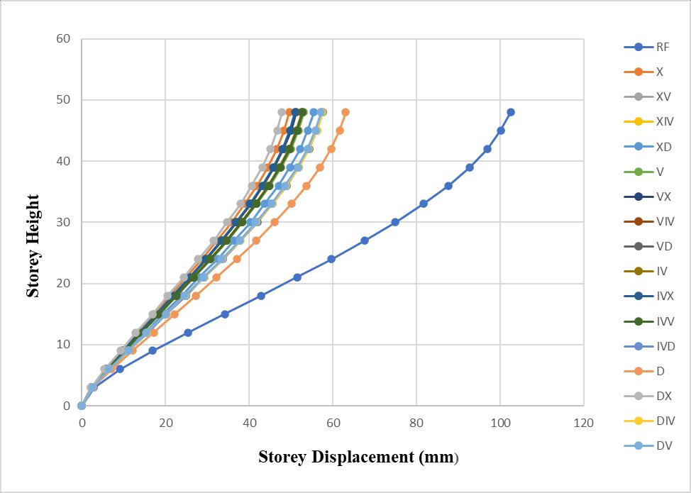
Fig 6 Maximum Storey Displacement (mm) for various Bracing Combinations
STOREY DRIFT
Table -11:StoreyDisplacement(mm)forHybridDBracings
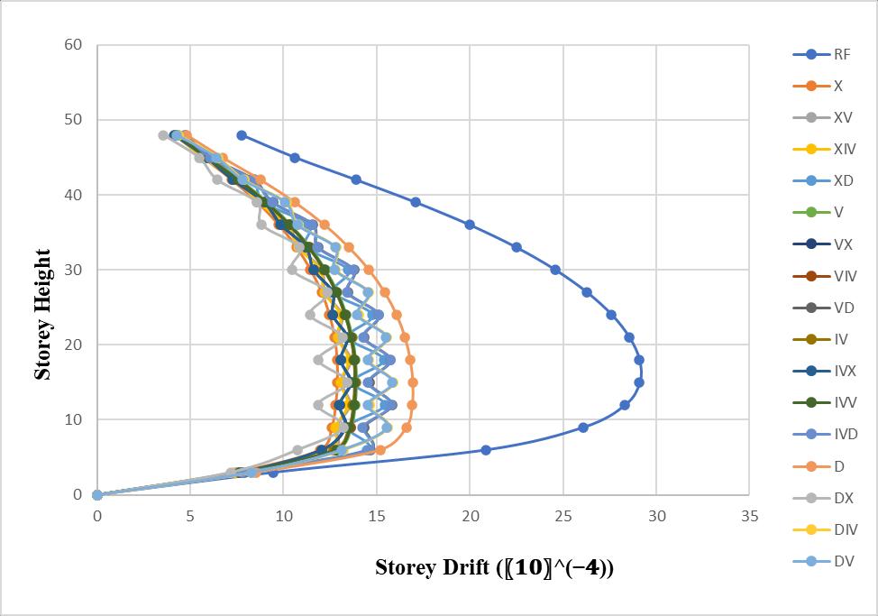
ThestoreydriftresultsofG+15modelsareshowninTable 12,13,14and15.TheplotofdriftversusstoreyforRFand Conventional bracing system and Hybrid bracing system modelsareshowninFig7
Table -12:StoreyDrift(10-4)forHybridXBracings
G+5
G+2
International Research Journal of Engineering and Technology (IRJET) e-ISSN: 2395-0056
Volume: 11 Issue: 12 | Dec 2024 www.irjet.net p-ISSN: 2395-0072
Table -13:StoreyDrift(10-4)forHybridVBracings Storey
Table -14:StoreyDrift(10-4)forHybridIVBracings
Table -15:StoreyDrift(10-4)forHybridDBracings
International Research Journal of Engineering and Technology (IRJET) e-ISSN: 2395-0056
Volume: 11 Issue: 12 | Dec 2024 www.irjet.net p-ISSN: 2395-0072
1. AccordingtoIS1893-2016,theTimePeriodissame for all models having same heights and the code doesnottakebracingsintoaccount.
2. The Time Period calculated according to IS 18932016(PartI)doesnotmatchwiththetimeperiod bymodalanalysisforbareframemodels,whereas tosomeextentitishighlightingtheinfluencewith Hybridbracingsystem.
3. TheTimePeriodinHybridbracingsystemisleastof DX-Bracings followed by IVX-Bracings and XIVBracingsforallthefloorheightduetotheincrease instiffnessbybracings.
4. TheTimePeriodinConventionalbracingsystemis least of X-Bracings followed by IV-Bracings, VBracingsandD-Bracingsforallthefloorheightdue totheincreaseinstiffnessbybracings.
5. FormallthemodelsBareframemodelsarehaving the highest time period due to less stiffness comparedtoallothermodels.
6. TheaverageTime Periodin Conventional bracing systemis15%morethanIS1893(Part1)-2016due toincreaseinstiffness.
7. TheaverageTimePeriodinHybridbracingsystem is 13% more than IS 1893 (Part 1)-2016 due to increaseinstiffness.
8. As the height of the structure increases there is decrease in Base Shear due to increase in Time Period.
9. TheBaseshearinHybridbracingsystemishighest ofIVX-BracingsfollowedbyXIV-BracingsandVXBracingsforallthefloorheight.
10. TheBaseshearinConventional bracingsystemis highest of X-Bracings followed by IV-Bracings, VBracingsandD-Bracingsforallthefloorheight.
11. ForallthefloorheightBareframemodelishaving the least Base Shear due to less self-weight the structurecomparedtoallotherbracedmodels.
12. The average Base shear of Conventional bracing systemis60%morethanBareframemodeldueto increaseinself-weightofthestructure.
13. TheaverageBaseshearofHybridbracingsystemis 59%morethanBareframemodelduetoincreasein self-weightofthestructure.
14. TheComparingofvariousXbracingscombinations, X-Bracing followed by XV, XIV and XD has a least storeydisplacement.
15. TheComparingofvariousVbracingscombinations, VX-Bracing followed by VIV, V and VD has a least storeydisplacement.
16. TheComparingofvariousIVbracingscombinations, IVX-BracingfollowedbyIV,IVVandIVDhasaleast storeydisplacement.
17. TheComparingofvariousDbracingscombinations, DX-Bracingfollowed byDV, DIVandDhasa least storeydisplacement.
18. TheStoreyDisplacementsinConventionalbracing systemisleastofX-BracingfollowedbyIV-Bracing, V-BracingandD-Bracingforallthefloorheight.
19. TheStoreyDisplacementsinHybridbracingsystem isleastofDX-BracingfollowedbyIVX-Bracingand XV-Bracingforallthefloorheight.
20. ForallthefloorheightBareframemodelsishaving thehighestdisplacementsduetolessstiffnessofthe structurecomparedtoallotherbracedmodels.
21. TheaverageStoreyDisplacementofConventional bracingsystemis53%lessthanBareframemodel duetoincreaseinstiffnessofthestructure.
22. TheaverageStoreyDisplacementofHybridbracing systemis49%morethanBareframemodeldueto increaseinstiffnessofthestructure.
23. TheDX-BracinghasleastStoreyDisplacementwhen compairedtoallothermodels.
24. TheComparingofvariousXbracingscombinations, X-Bracing followed by XIV, XV and XD has a least storeydrift.
25. The Comparing various V bracings combinations, VX-Bracing followed by VIV, V and VD has a least storeydrift.
26. TheComparingvariousIVbracingscombinations, IVX-BracingfollowedbyIV,IVVandIVDhasaleast storeydrift.
27. The Comparing various D bracings combinations, DX-Bracingfollowed byDV, DIVandDhasa least storeydrift.
28. TheStoreyDriftinConventionalbracingsystemis least of X-Bracing followed by IV-Bracing, IVBracingandD-Bracingforallthefloorheight.
International Research Journal of Engineering and Technology (IRJET) e-ISSN: 2395-0056
Volume: 11 Issue: 12 | Dec 2024 www.irjet.net p-ISSN: 2395-0072
29. TheStoreyDriftinHybridbracingsystemisleastof DX-BracingfollowedbyIVX-BracingandVX-Bracing forallthefloorheight.
30. ForallthefloorheightBareframemodelsishaving the highest storey drift due to decrease in lateral stability to the structure compared to all other bracedmodels.
31. The average Storey Drift of Conventional bracing systemis57%lessthanBareframemodel dueto increaseinlateralstabilityofthestructure.
32. TheaverageStoreyDriftofHybridbracingsystemis 52%morethanBareframemodelduetoincreasein lateralstabilityofthestructure.
33. Storey Drift of all the models are within the permissible limit i.e 0.004 times the height of the storeyasperIS1893-2016.
34. InHybridbracingsystemthereisirregularshapeof graphinstoreydriftitisduetoalternativebracing ateachfloorofthebuilding.
35. The DX-Bracing has least Storey Drift when compairedtoallothermodels.
36. DX-HybridBracingSystemperformswellinStorey DisplacementandStoreyDriftwhencompairedto all other Conventional braced models as well as Hybridbracedmodels.
1. Dasare Shivani Balaji and Prof. Mrs. Kariappa M.S. (2022), “Analysis and Comparative Study of Steel Bracing in Reinforced Concrete Building Under Seismic and Wind Load”, International Research JournalofModernizationinEngineeringTechnology andScience,e-ISSN:2582-5208Volume:04,Issue:07, PageNumber:1621-1626.
2. BhavikRSuthar,Dr.IndrajitN.Patel,Prof.VimleshV. AgrawalandProf.VishalPatel(2021),“StudyofG+ 20StoreyRCFramedStructurewithStructuralSteel Braces”,InternationalJournalofAdvancedResearch in Science, Communication and Technology (IJARSCT) Volume 7, Issue 2, ISSN (Online) 25819429,PageNumber:211-223.
3. Prof. Shashikant Manekari, Mr.Sagar Dhotre, Miss.Aparana Sathe, Mr. Ganesh Havile, Mr.Aniket RathodandMr.NavinGajul(2021),“AnalysisofMulti Storey Building by using Steel”, International Research Journal of Engineering and Technology (IRJET)Volume:08,Issue:07,e-ISSN:2395-0056,pISSN:2395-0072,PageNumber:2004-2009.
4. Vishal B. Mondal, G.D. Dhawale and Rutuja K. Kakpure(2020),“BehaviourstudyofRCCBuilding withandwithoutbracingUsingSTAAD.Pro”,Journal ofEmergingTechnologiesandInnovativeResearch (JETIR) September 2020, Volume 7, Issue 9 ISSN2349-5162,PageNumber:271-276.
5. Javed Ul Islam, Mayank Mehandiratta and Rohit Yadav (2019), “Earthquake Resistant Design-A
comparativeanalysisofvariousbracingsystemwith RC-frame”, International Journal of Engineering DevelopmentandResearch,Volume7,Issue3|ISSN: 2321-9939,PageNumber:79–85.
6. Nikhil A. Sherje and Manish Chudare (2018), “Analytical Study on Seismic Response Control Of MultistoreyRCBuildingFrameUsingVariousTypes Of Bracing Systems”, International Journal of CreativeResearchThoughts(IJCRT),Volume6,Issue 2April2018|ISSN:2320-2882,PageNumber:950962.
7. RakshithKLandSmitha(2017),“EffectofBracings onMultistoriedRCCFrameStructureunderDynamic Loading”,InternationalJournalofAdvanceResearch, Ideas and Innovations in Technology, ISSN: 2454132X(Volume3,Issue4),PageNumber:696-705.
8. NitinBhojkarandMaheshBagade(2015),“Seismic Evaluation of High-rise Structure by Using Steel BracingSystem”,InternationalJournalofInnovative Science, Engineering & Technology, Vol. 2 Issue 3, March2015,ISSN2348–7968,PageNumber:264269.
9. Umesh.R.Biradar and Shivaraj Mangalgi (2014), “SeismicResponseOfReinforcedConcreteStructure By Using Different Bracing Systems”, International JournalofResearchinEngineeringandTechnology eISSN:2319-1163|pISSN:2321-7308,Volume:03 Issue:09,PageNumber:422-426.
10. JagadishJ.SandTejasD.Doshi(2013),“AStudyon Bracing Systems on High Rise Steel Structures”, International Journal of Engineering Research & Technology(IJERT),ISSN:2278-0181Vol.2Issue7, PageNumber:1672-1676.
11. ViswanathK.G,PrakashK.B,andAnantDesai(2010), “SeismicAnalysis of SteelBracedReinforcedConcreteFrames”, InternationalJournalof Civiland StructuralEngineeringVolume1,No1,ISSN0976–4399,PageNumber:114-122.
12. MarcBadoux andJames O. Jirsa (1990),“Steel Bracingof RC Frames for SeismicRetrofitting”, JournalofStructuralEngineering, Vol. 116, No. 1, PageNumber:55-74.