
International Research Journal of Engineering and Technology (IRJET) e-ISSN: 2395-0056
Volume: 11 Issue: 12 | Dec 2024 www.irjet.net p-ISSN: 2395-0072

International Research Journal of Engineering and Technology (IRJET) e-ISSN: 2395-0056
Volume: 11 Issue: 12 | Dec 2024 www.irjet.net p-ISSN: 2395-0072
Kareddy Sai Nikhitha1 and Dr. K. Bhaskar2
1M.tech, Student, Dept. of Electrical and Electronics Engineering, JNTUHUCEST, Hyderabad, India. 2Professor of Electrical and Electronics Engineering, JNTUHUCEST, Hyderabad, India.
Abstract - Electric vehicles (EVs) offer a sustainable solution to fossil fuel depletion and environmental degradation. With zero emissions, EVs are more efficient than traditional fuel-powered vehicles and play a key role in reducing greenhouse gases and air pollution, supporting climate goals. Despite these benefits, EV adoption is limited by battery-related challenges, particularly in charging efficiency. To address this, it is crucial to explore effective battery charging methods. Lithium-ion batteries, widely used due to their superior performance, require optimized charging techniques for efficiency and longevity. This project explores different methods for charging lithium-ion batteries, including constant voltage charging, constant current charging, a combination of constant current and constant voltage charging, as well as multistep constant current charging. MATLAB/Simulink software is used to simulate and analyze these methods, providing insights into their charging characteristics. Furthermore, electricity may move both ways between the EV battery and the grid thanks to the combination of bi-directional AC-DC and DC-DC converters, which improves grid stability and facilitates effectiveenergytransfer.
Key Words: EVC Systems, CC, CV, CC-CV, MSCC, DC-DC Converter, AC-DC Converter
The electrification of transportation is a critical step toward a sustainable future, with electric vehicles (EVs) leading the charge to reduce carbon emissions and dependence on fossil fuels. As environmental initiatives gainglobalmomentum,theimportanceofEVscontinuesto grow,spurringadvancementsinvehicletechnologyandthe infrastructure that supports them. At the core of this infrastructure is the EV charging system, a vital element thatdeliversenergyfromthegridtopowertheEVbattery. The efficiency, speed, and reliability of charging systems directly impact the practicality and attractiveness of owninganEV,especiallyasthenumberofEVsontheroad increases
Fast and efficient charging systems are essential for multiple reasons. First, minimizing charging times is vital to increasing EV appeal, as long waits can deter adoption when compared to the quick refuelling of internal combustion engine vehicles. A robust, rapid charging system can ease these concerns and make EVs more
appealingtoawidermarket.Second,efficiencyduringthe grid-to-battery power transfer must be maximized to reduce energy loss. Inefficient systems not only waste energy but also produce excess heat, which can reduce battery lifespan and raise safety concerns. Enhancing energy efficiency in charging systems is essential to meet thegrowingdemandforEVssustainably.
Reliability and safety are equally crucial for EV charging systems. These systems must function consistently across diverse conditions, guarding against electrical hazards, preventing overcharging, and ensuring stable voltage and currentdelivery.Reliablechargingsystemsalsocontribute to battery longevity, reducing degradation and enhancing overall vehicle performance. Additionally, as EVs connect with smart grids, charging systems must manage energy flows intelligently, potentially supporting bidirectional energy transfer (vehicle-to-grid technology) to balance griddemand.ThiscapabilityallowsEVstoserveasmobile energy storageunits,improvinggridstabilityduring peak demand. In response to these needs, various charging strategies have been developed, each addressing key aspects such as battery health, energy efficiency, and charging speed. Manufacturers continue to innovate, aiming to create systems that meet the diverse requirements of EVs, from compact passenger cars to largercommercialvehicles.
The paper is structured as follows: Section II outlines the primary block diagram of the proposed model along with the circuit design. Section III describes the charging methods and control strategies used. Section IV contains the simulation model, whereas section V has the simulationresultsanddiscussion.SectionVIdescribesthe proposedsystem'sconclusion.
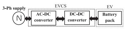
Figure 1 illustrates the structure of a typical Electric Vehicle Charging System (EVCS). The three-phase AC source that powers the system is first transformed via an AC-DC converter. In order to prepare the AC input for additionalprocessing,thisfirststepconvertsittoDC.After that, the DC-DC converter modifies the voltage to satisfy the needs of the battery pack in the electric car. This configuration ensures efficient energy transfer from the power grid to the EV battery, facilitating reliable and controlledchargingforoptimalbatteryperformance.
International Research Journal of Engineering and Technology (IRJET) e-ISSN: 2395-0056
Volume: 11 Issue: 12 | Dec 2024 www.irjet.net p-ISSN: 2395-0072
2.1 Design of the Bi-directional AC–DC Converter
Through filter inductance, the bidirectional three-phase AC-DCconverterisconnectedtothedistributiongrid.The DC output voltage of the converter can be stated as follows.
Here, representsthevoltageofthelinethree-phase AC sources (in volts), and ‘m’ denotes the modulation index.TheDC-linkcapacitanceisdeterminedbasedonthe followingcriteria.
Here ,f representsthe source's frequency (in hertz), Δ is the ripple voltage (in volts), and as maximum DCpower(inwatts).
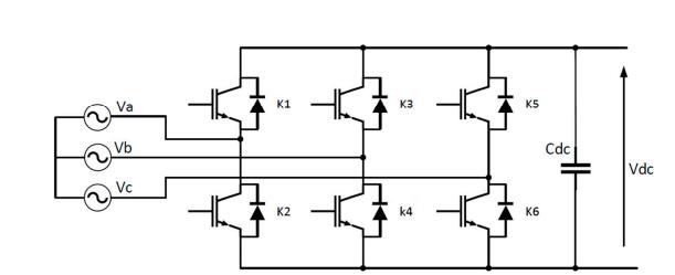
Figure2.DesignofaBidirectionalACtoDCConverter Model
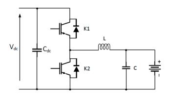
2.2 Design of a Bidirectional DC-DC Converter
The bi-directional DC-DC converter, which is placed between the AC-DC converter and the EV battery pack, operates in buck mode while charging and boost mode whendischarging.Becauseofthis,thebatterysideinductor isintendedtooperateinbothmodes.
Both the buck and boost modes inductor values are determinedusingthefollowingformulas.
Here, istheDC-linkvoltage(involts), isthe batteryvoltage(involts), istheswitchingfrequency(in Hertz)and isthefilterinductoronthebatteryside(in Henrys).
Forbatterycharging,thedc-dcconverter'soutputfilter capacitor( ))iscomputedusing
Here represents the ripple voltage at the output (in volts).
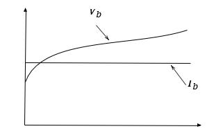
3.1 Constant Voltage Charge Method
Thechargingcharacteristicsofthisapproacharedepicted inFig.4.Asthenameimplies,thebatteryvoltageremains relatively constant. After reaching the predetermined value during the charging process. It is essential to adjust thechargingvoltageinlinewiththerecommendedcharge and temperature parameters. Setting an incorrect voltage can lead to either overcharging or undercharging the battery.
Onthe otherhand,the charging current graduallydrops. It reaches its maximum at the start of the charging cycle, whenitmustbecontrolledtoprotectthedevices,andthen progressively decreases to its lowest point at the end of the charging time. In other words, the current that the battery draws from the power source decreases as its state of charge grows. The charging speed of this method isoftenslowerthanthatof otherchargingmethods.Basic controltechniques,however,makeiteasytomanage.
International Research Journal of Engineering and Technology (IRJET) e-ISSN: 2395-0056
Volume: 11 Issue: 12 | Dec 2024 www.irjet.net p-ISSN: 2395-0072
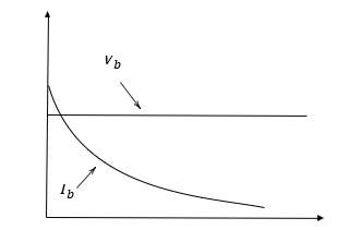
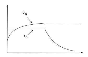
Fig. 5 shows the charging properties of this technique. Another basic charging method that employs a steady stream is this one. The current in a string of cells connected in series stays consistent during the charging processandisuniformacrosseachindividualcell.Whilea larger charging current may result in dangerously high battery temperatures, a lower charging current will increase the total charging time. Therefore, selecting an appropriate charging current is crucial for battery safety. Overcharging with a constant current method can also reduce the battery's lifespan. As charging progresses, the battery's voltage increases due to the accumulation of charge. Because the current is constant and doesn't drop overtime,thisapproachallowsforquickercharging.
3.3 Constant Current-Constant Voltage Charging
Fig.6showsthechargingcharacteristicsofthis approach. This hybrid method raises the voltage gradually after starting with a steady current. The voltage is kept steady while the current drops in accordance with the battery's state of charge (SOC) until it achieves its assigned value, whichisusuallyclosetofullcharge.Whenthecurrentfalls to a minimal value set by the manufacturer, the charging process ends. This popular charging algorithm combines the advantages of constant voltage and constant current techniques.. It is particularly suited for smaller batteries, where voltage is more evenly distributed across the cells. However, in high-voltage batteries, where multiple cells are connected in series, voltage may not be as evenly
distributed. In general, this technique is quicker than conventional constant voltage charging and helps avoid overcharging.
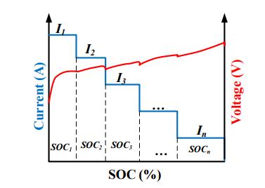
Multi-Stage Constant Current (MSCC) charging is an advanced method that breaks the charging process into several stages, each utilizing a specific constant current. Thistechniqueisdesignedtooptimizechargingefficiency, enhance safety, and increase the lifespan of batteries, particularly lithium-ion batteries, which are frequently usedinenergystorageandelectriccarapplications.
The MSCC charging technique modifies the charging procedure based on the state of charge (SOC) of the battery. Initially, a higher current is used to quickly raise the SOC, enabling faster charging when the battery is capableofhandlingincreasedcurrentwithoutrisk.Asthe SOC rises and the battery approaches its full capacity, the chargingcurrentisgraduallyreducedinstages.Thisstepdown in current helps to limit heat generation, prevent overcharging, and reduce stress on the battery, thus helping to minimize wear and extend its lifespan. This multi-phase approach is especially beneficial in applications where battery health, charging speed, and efficiency are critical considerations. By controlling currentflowthrougheachstage,MSCCchargingensuresa more balanced and stable charging cycle, making it ideal for
devices and systems that demand reliable, long-lasting batteryperformance
Volume: 11 Issue: 12 | Dec 2024 www.irjet.net p-ISSN: 2395-0072
Fig.8showsthecontrollercircuit,whichismadetosatisfy the particular requirements of the charging method. Consistent voltage charging maintains a consistent voltage, whereas Constant Current (CC) charging keeps the current at a constant level. The battery voltage hits a predeterminedthresholdintheCC-CVchargingtechnique, at which point the current progressively drops while the voltagestayssteady.TheDC-DCconverteradjuststheduty cycle of the IGBT switches using voltage and current feedback to ensure these charging requirements are met. Asa result,the dutycycleis not fixed butvaries based on the battery's voltage and current needs. The carrier frequency of the Pulse Width Modulation (PWM) signal is 10 kHz. The maximum and lowest duty cycles of the switches are constrained by a saturation limiter. The controllercircuitseeninthepictureintegratesvoltageand currentcontroloperationsandisparticularlymadeforthe CC-CVchargingtechnique.
ThereferencecurrentfortheDC-DCconverterisproduced using a novel MSCC control technique. Fig. 9 displays the block diagram that demonstrates this MSCC control approach. This method uses the charging/discharging (Ch/Dch) mode selection signal and the battery's state of charge(SOC)tocalculatethereferencecurrent. When the SOCislessthan80%duringthechargingphase(Ch/Dch= HIGH),thereferencecurrentisinitiallysetat33.5A.Upon reaching 80% SOC, the reference current is lowered to 23.5 A. The reference current drops to 13.5 A if the SOC hits or is above 90%.Once the SOC hits 100%, the referencecurrentissettozero.Thereferencecurrent
is kept at 33.5 A during the discharging phase (Ch/Dch = LOW), while the SOC is between 20% and 100%. Zero reference current is used if the SOC falls below 20%. Faster battery charging, fewer transients during current changes, and improved control over battery voltage by reducing the charging current particularly during the switchfromCCtoCVmode arejustafewbenefitsofthe suggestedMSCCtechnique.
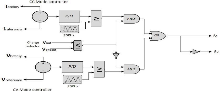
Figure.8 ThecontrolsystemforConstantVoltage(CV), ConstantCurrent(CC),andConstantCurrent-Constant Voltage(CC-CV)charging.

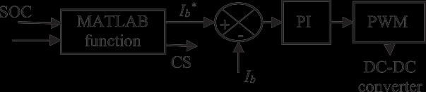
Figure9ProposedMSCCcontrolmethodfortheDC-DC converter.
The Simulink models shown in Figures 10, 11, 12 and 13 were created and run using the MATLAB/Simulink environment. Figure 10 presents the simulation model of the grid-connected Electric Vehicle Charging Station (EVCS) system, which illustrates how the charging infrastructure integrates with the grid to manage energy flow.ThebidirectionalAC-DCcontrollersimulationmodel, whichisinchargeofconvertingandcontrollingelectricity betweentheACgridandtheDCsideoftheEVCS,isshown in Figure 11. This facilitates energy exchanges between vehiclesandthegrid(V2GandG2V).Figure12showcases the DC-DC controller simulation model, which supports various charging methods such as CC, CV, and CC-CV, to assesstheireffectsonbatteryperformance.Finally,Figure 13 illustrates the simulation model of the MSCC (MultiStage Constant Current) controller, which is designed to enhance charging efficiency by adjusting current in multiplestagesaccordingtotheSOCofthebattery.
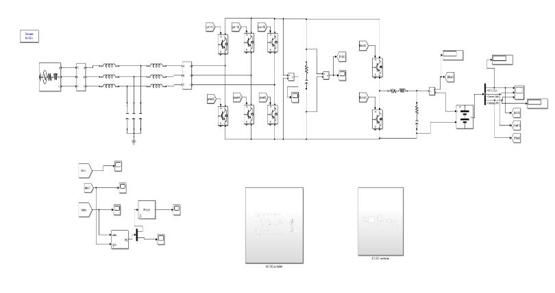
10.SimulinkmodelofEVCSconnectedtogrid
International Research Journal of Engineering and Technology (IRJET) e-ISSN: 2395-0056
Volume: 11 Issue: 12 | Dec 2024 www.irjet.net p-ISSN: 2395-0072
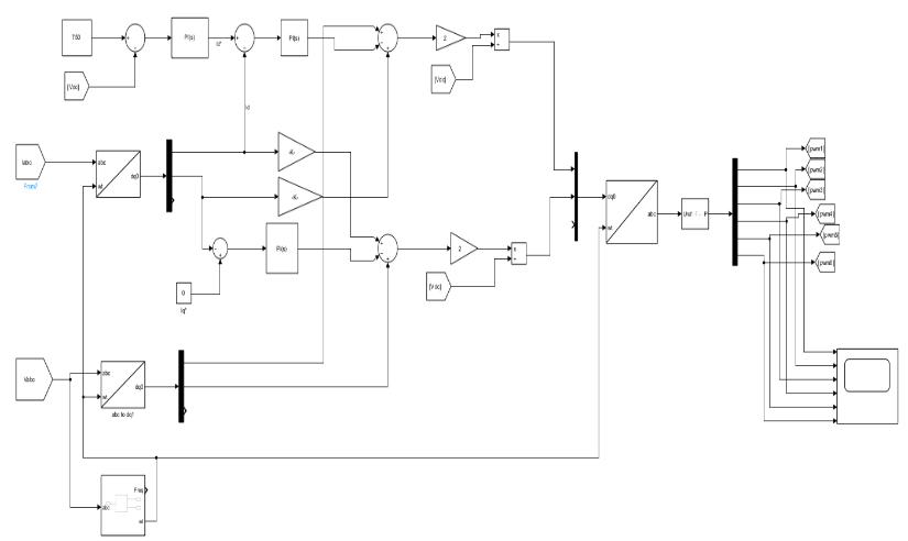
Figure11.SimulinkmodelofAC-DCcontroller
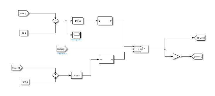
Figure12.SimulinkmodelforcontrollingaDC-DC converterinConstantCurrent(CC),ConstantVoltage(CV), andcombinedCC-CVchargingmodes.
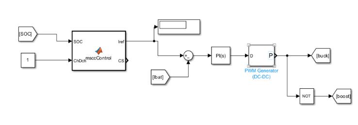
Figure13.SimulinkmodelforDC-DCcontrollerdesigned forMulti-StageConstantCurrent(MSCC)charging.
SIMULATION PARAMETERS
S.no
1
2
3
4
5
6
7 Switchingfrequency
This section presents the simulation results of the proposed system employing different charging methods: CC, CV, CC-CV, and MSCC. Figures 14, 15, 16, and 17 illustrate the battery voltage, current, and State of Charge (SOC)foreachofthesechargingapproaches.
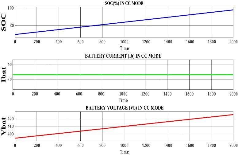
Figure14.WaveformsforStateofCharge(SOC),voltage (Vb),andcurrent(Ib)inCCchargingmode
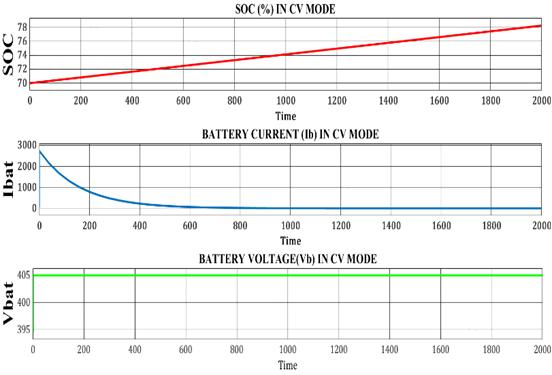
Figure15. WaveformsforStateofCharge(SOC),voltage (Vb),andcurrent(Ib)inCVchargingmode.
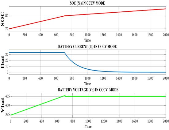
Figure16WaveformsforStateofCharge(SOC),voltage (Vb),andcurrent(Ib)inCC-CVchargingmode
International Research Journal of Engineering and Technology (IRJET) e-ISSN: 2395-0056
Volume: 11 Issue: 12 | Dec 2024 www.irjet.net p-ISSN: 2395-0072
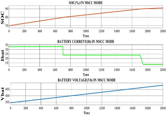
Figure17.WaveformsforStateofCharge(SOC),voltage (Vb),andcurrent(Ib)inMSCCchargingmode
The active power on the grid side is measured at 16.49 kW, while the battery side receives 13.22 kW. This indicates a power loss of 3.27 kW during the energy transfer process. These losses account for approximately 19.82% of the total power supplied by the grid. Such losses can be attributed to various factors, including line resistance, switching losses in power converters, and thermal dissipation in system components. Despite these losses, the system demonstrates a reasonable level of efficiency for practical applications, ensuring reliable energy transfer tothe battery.Enhancing the efficiency of inverters and reducing resistive losses in power lines could significantly minimize energy dissipation. Additionally,betterthermalmanagementstrategieswithin the battery and power electronics could further optimize performance.Thenegligiblereactivepoweronthebattery side emphasizes the effectiveness of the system in transferring energy predominantly through active power, reflectingitssuitabilityforhigh-performanceapplications.
Charging
CV charging 2000 s 70-78 404-405 volts Low
CC charging 2000 s 70-98 395-427 volts High
CC-CV charging 2000 s 70-85 395-405 volts Moderate
MSCC charging 2000 s 70-92 395-409 volts Moderate
The table compares four EV battery charging methods CV, CC, CC-CV, and MSCC based on their effects on State of Charge (SOC), voltage rise, and temperature rise over
2000seconds.CVcharging,whichshowsthesmallestSOC increase (70% to 78%) and minimal voltage rise (404.8V to 405.6V), is the safest, though less efficient. CC charging achieves the highest SOC increase (70% to 98%) but also causes significant voltage (395V to 427V) and temperature rises, which may stress the battery. The hybridCC-CVmethodbalancessafetyandefficiencywitha moderate SOC increase (70% to 85%), a safer voltage range (395V to 405V), and moderate thermal impact. MSCC offers a promising alternative with a high SOC increase (92%), moderate voltage rise (395V to 409V), and balanced thermal management, making it a safer option compared to CC. Each method involves trade-offs, withCCprioritizingspeedandtheothersbalancingsafety, efficiency,andthermalcontrol.
The variations in temperature across different charging methods result from how energy is delivered to the battery. A set voltage is applied to the battery durithe Constant Voltage (CV) charging procedure. As the battery approaches full charge, its internal resistance increases. To maintain the constant voltage, the charging current automaticallydecreases.Thisgradualreductionincurrent minimizes the rate of energy input, leading to reduced heatgenerationandasaferchargingprocess.
Conversely, Constant Current (CC) charging involves a steady high current input, which can increase internal resistance within the battery cells. This higher resistance results in more heat dissipation, leading to a significant temperature rise. To mitigate the temperature rise associatedwithCCcharging,CC-CVchargingcombinesthe initial rapid charging phase of CC with the controlled finishing phase of CV. This approach balances charging speed and thermal management. Modified Constant Current (MSCC) charging further refines this process by dynamicallyadjustingthecurrentthroughoutthecharging cycle. By intelligently controlling the current flow, MSCC minimizes heat generation, ensuring faster charging withoutcompromisingbatteryhealth.
The comparison of the CV, CC, CC-CV, and MSCC charging techniques emphasizes how important it is to strike a balance between battery safety, charging efficiency, and heat control. Because it causes less thermal and electrical stress,ConstantVoltage(CV)chargingisthesafestchoice, even though it results in slower charging. It is characterized by the smallest State of Charge (SOC) increase (70% to 78%) and the least amount of voltage rise (404.8V to 405.6V). Constant Current (CC) charging, ontheotherhand,increasesSOCthefastest(70%to98%) butatthecostofconsiderablevoltage(395Vto427V)and temperature increases, which could hasten battery deterioration.
International Research Journal of Engineering and Technology (IRJET) e-ISSN: 2395-0056
Volume: 11 Issue: 12 | Dec 2024 www.irjet.net p-ISSN: 2395-0072
In comparison to CC, the CC-CV approach offers a moderate SOC rise (70–85%), preserves an acceptable voltagerange(395–405),andlowersthermal stress.With a notable 92% SOC gain, a moderate voltage increase (395V to 409V), and balanced thermal performance, the Modified Constant Current (MSCC) approach is a viable substitute for reaching both effectiveness and security. Theseresultshighlighthowcrucialitistochoosethebest charging approach depending on the intended trade-off between battery longevity, charging speed, and temperature control. Improving the charging technique cangreatlyextendthelife,safety,andoverallperformance ofEVbatteries.
[1] S. A. El-Bataway and W. G. Morsi, “Distribution transformer’s loss of life considering residential prosumers owning solar shingles, high-power fast chargers and second-generation battery energy storage,” IEEE Trans. Ind. Informat., vol. 15, no. 3, pp. 1287–1297, Mar.2019
[2]S.Kewat,B.Singh,andI.Hussain,“Powermanagement in PV-battery- hydro based standalone microgrid,” IET RenewablePowerGener.,vol.12,no.4,pp.391–398,2017
[3] S. Habib, M. M. Khan, F. Abbas, L. Sang, M. U. Shahid, and H. Tang, “A comprehensive study of implemented international standards, technical challenges, impacts and prospects for electric vehicles,” IEEE Access, vol. 6, pp. 13866–13890,2018.
[4]N.Zhou,J. Wang,Q. Wang,andN.Wei, “Measurementbased harmonic modeling of an electric vehicle charging station using a three-phase un- controlled rectifier,” IEEE Trans.SmartGrid,vol.6,no.3,pp.1332–1340,May2014.
[5] J. Gallardo-Lozano, M. I. Milanés-Montero, M. A. Guerrero-Martinez,andE.Romero-Cadaval.,“Three-phase bidirectional battery charger for smart electric vehicles,” in Proc. IEEE 7th Int. Conf.-Workshop Compat. Power Electron.,2011,pp.371–376.
[6]A.N.Devi,S.KakkarandN.ImamYusuf,"Analysisand Simulation of Charging/Discharging of Lithium-Ion Battery in Electric Vehicles," 2024 IEEE Third InternationalConferenceonPowerElectronics,Intelligent Control and Energy Systems (ICPEICES), Delhi, India, pp. 37-41,2024.
[7] A. Rachid, H. E. Fadil and F. Giri, "Dual-stage CC-CV charge method for controlling DC-DC power converter in BEV charger," 2018 19th IEEE Mediterranean Electrotechnical Conference (MELECON), Marrakech, Morocco,pp.74-79,2018.
[8] K. R. Ahmad, P. J. Grbović, G. De Falco and R. Petrella, "Li-Ion Battery Fast Charging Methods: Review and Comparison," 2024 IEEE 10th International Power Electronics and Motion Control Conference (IPEMC2024ECCEAsia),Chengdu,China,pp.5131-5137,2024
[9] A. Sharma and M. Veerachary, "A DC-DC Bidirectional Converter with Improved Mode Transition Technique," 2018IEEEInternationalConferenceonPowerElectronics, DrivesandEnergySystems(PEDES),Chennai,India,pp.16,2018.
[10] A. Ramelan et al., "Design and Simulation of The Multistage Constant-Current Charging System with Passive Balancing BMS for Lithium-Ion Batteries," 2022 International Conferenceon ICTforSmartSociety(ICISS), Bandung,Indonesia,pp.1-7,2022.
[11] W. Chen, J. Chen, Z. Chen and H. Lin, "A SOC-Based FastChargingOptimizationStrategywithCoupledElectroThermal-Aging Model for Lithium-ion Batteries," 2022 12th International Conference on Power and Energy Systems(ICPES),Guangzhou,China,pp.725-730,2022.
[12] U. Sharma and B. Singh, "A Bidirectional Onboard Charger With Multistep Constant Current Charging Capability," in IEEE Transactions on Transportation Electrification,vol.9,no.1,pp.1227-1237,March2023.
[13] R. Tailor, K. Chopra, M. K. Shah and K. R. Niazi, "A Comprehensive Study on Impact of EVs on Distribution System and Allocation of EVCS," 2024 1st International Conference on Innovative Sustainable Technologies for Energy, Mechatronics, and Smart Systems (ISTEMS), Dehradun,India,pp.1-5,2024.
[14] B. Geng, J. K. Mills and D. Sun, "Two-Stage Energy Management Control of Fuel Cell Plug-In Hybrid Electric Vehicles Considering Fuel Cell Longevity," in IEEE Transactions on Vehicular Technology, vol. 61, no. 2, pp. 498-508,Feb.2012.