
HOP[E]
PROMOTING SUSTAINABLE BREWING THROUGH A CIRCULAR MODEL
James Goodwin ( a R30022)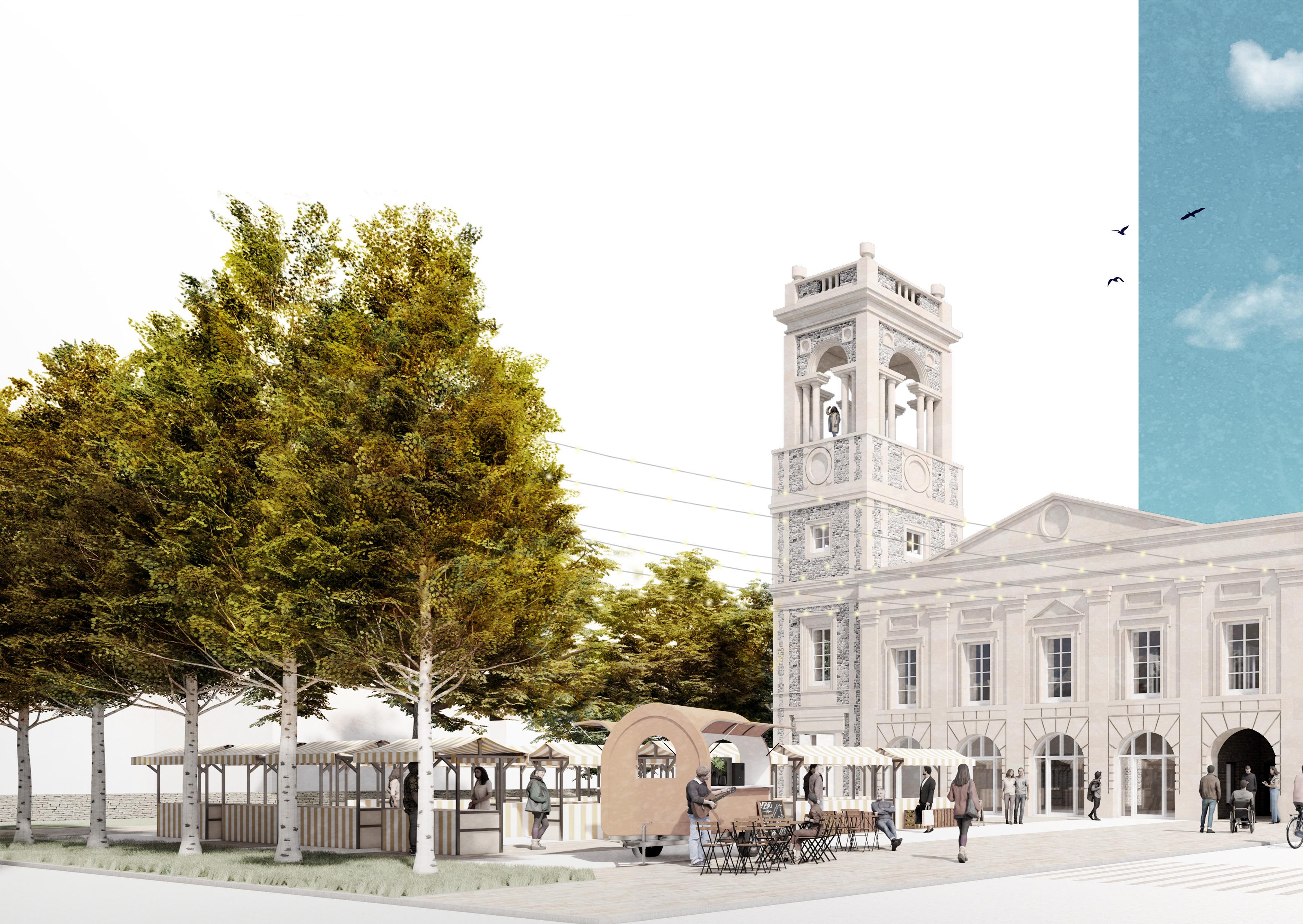
Acknowledgements:
I would like to thank all of the tutors, consultants and visiting critics for their support and expertise, which has been invaluable through the course of this project.
Julia Kashdan-Brown | Architectural Tutor
Matthew Wickens | Studio Co-ordinator and Head of Year
Andy Jarvis | Environmental Tutor
Marc Dix | Landscape Tutor
Tim Mander | Structural Tutor
John Griffiths | Tectonics Tutor
Craig Sheach | Visiting Critic
James Gallie | Visiting Critic
Steve Fitzwilliam | Visiting Critic
Produced for assessment for Unit AR30022 Design Studio 4.2 as part of BSc (Hons) Architecture at the University of Bath.
A Brief History of Brewing
A Possible Solution
The Cyclical Process
Client, Stakeholders and Aims
Schedule of Accommodation
The Site
Environmental Analysis
Active Frontages
The Historic Context
Design Drivers
Massing Strategy
Proposed Demolitions
Healing the Fractured Fabric
The Users
Arrival
Landscaping
Ground Floor Plan
The Taproom
First Floor Plan
A Patchwork of Materials
Deliveries and Goods Circulation
Structure and Tectonics
Integrated Tectonic Principles
Scales of Intervention
Structural Grids
Differentiating New and Old
Materiality
Resource Flows
Embodied Carbon
Typical Buildups
The Butterfly Truss
Typical Connection Assembly Sequence
The Roof
The Brewing Hall
A Language of Reuse
Environmental Strategies
Integrated Environmental Principles
A Zone Based Approach
Servicing Strategy
Retrofit Strategy
The Taproom
Brewing Hall
Pretreatment Labs and Power Generation
Hydroponics Hall
Optimising the Basement
Acoustics
Lighting
Fabric Efficiency
The Tower
Enhancing Biodiversity
The Responsible Use of Water
A Holistic Closed Loop System
Quantifying Further Carbon Savings
The Future
Approved Document B
Approved Document M
Document L
] BRIEF
A Brief History of Brewing
“The History of Beer, quite literally, is the history of Human Civilisation”[1]
Brewing can be traced back over 5000 years to ancient Babylonia, to a drink known as ‘Kas’ - the earliest form of beer. Archaeologists have discovered shards of pottery from the later Sumerian era studded with calcium oxalate, a grain deposit known as ‘beer stone’.
It is first recorded in Europe in the 4th and 5th centuries, where monasteries set up breweries to generate income, their beer sustaining travellers and pilgrims[2]. From these early days until relatively recently, beer was safer to drink than ‘fresh’ water, and was the ‘drink of choice’ for entire populations.
Historically, beer was the safer option to water, as ‘fresh’ water sources were often contaminated with sewage, disease or bacteria. It was also nutrient and calorie dense[3]. To this day, consuming beer still has several social benefits and helps to bring people together. In small amounts, beer can help to decrease the risk of diseases such as heart disease, neuro-degenerative diseases, and type 2 diabetes[4], although has several negative effects if drunk to excess.
A Wasteful Process
In 2020, the global annual beer production was estimated at 1.82 billion hL (1hL=100L)[10]. Of all waste produced during this process, wet BSG (Brewers Spent Grain) accounts for 85%[5]. Annually, 39 million tons of BSG are produced worldwide[6]
For every 100 litres of beer produced, 20kg of spent grains are created as a waste product[7]. These currently have little opportunity for further use outside of feedstocks or compost, and around 20% is sent to landfill. For every ton of BSG sent to landfill, 513kg CO2 is released[8] .
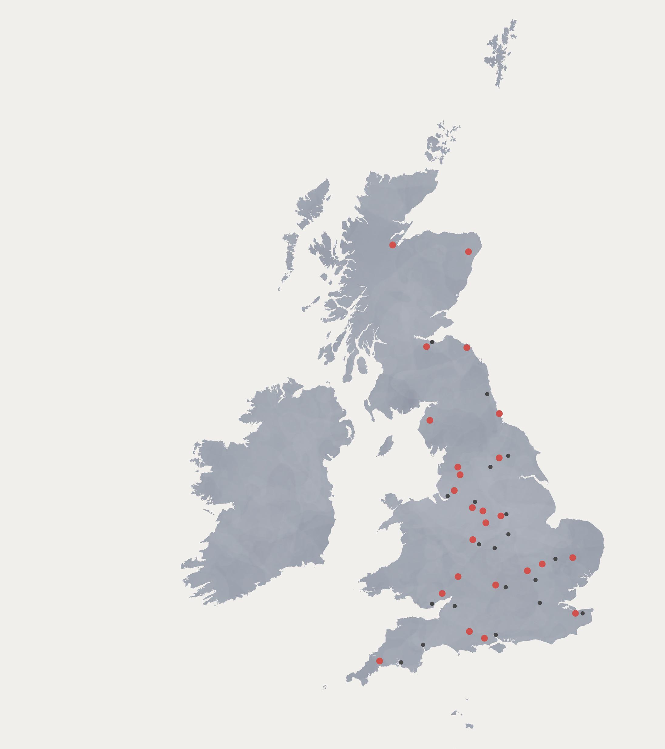
Today, there are over 2,400
major breweries across the UK...[9]
Producing 750,000 tons of BSG annually...
Equating to 384,750 tons CO2.
[That’s equivalent to over 1780 full flights between London and New York]
A Possible Solution GROW
PRODUCE ON SITE
USING OVERLOOKED OR UNWANTED INGREDIENTS
GENERATED FROM WASTE PRODUCTS

Ton BSG

In 2022, the UK produced 37.5 million hL of beer, ranked 4th in the EU[10]. Using the ratios discussed previously, it can be estimated that the approximate annual UK production of brewers spent grains is 750,000 tons.
Anaerobic digestion processes can turn these grains into hydrogen; a clean fuel which can be turned into electricity using a fuel cell[11]. The only waste emission is water; the ‘left over’ BSG can be used for compost. A circular model is critical to generate maximum potential from this otherwise waste product.
Tons BSG
TWh Power
This would allow us to power 1.1 million homes for an entire year.

The Cyclical Process
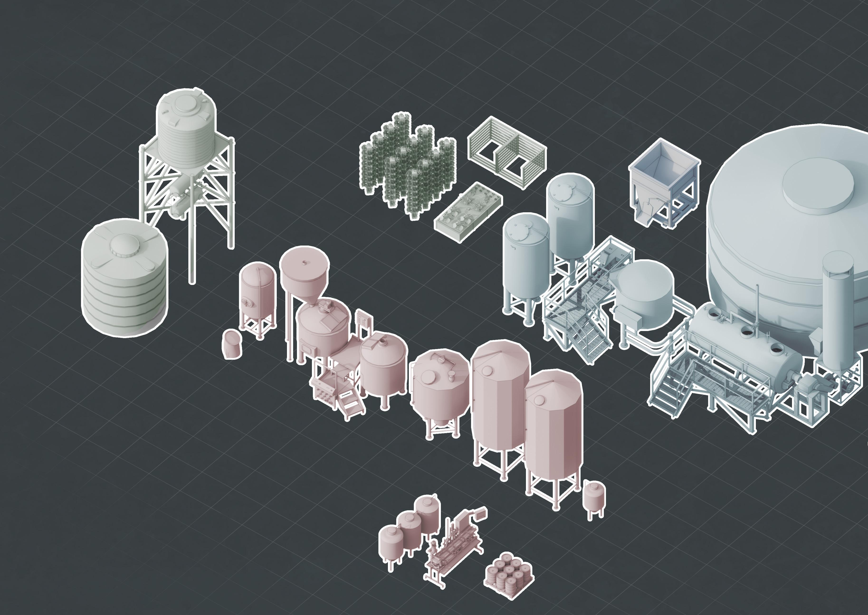
The building is constructed around a cyclical brewing process, blending a historic craft with cutting edge modern science to propose a system where waste products from the brewing process are converted into power. This utilises an anaerobic digestion process to convert spent barley and other grains into bio-hydrogen, which is then turned into power using a fuel cell. The only waste product is water.
To maximise the power generation of each grain, it is necessary to ‘pre-treat’ the waste BSG using both chemicals and heat; breaking down the cell walls of the grains to better expose them to the digestion process. Each digestion cycle takes approximately 40 days, in which solid and liquid BSG solutions are passed through GBR (solid) and AD (liquid) vessels. Waste BSG can be constantly added to the cycle, with the solid wastes removed at infrequent intervals. Bio-hydrogen is collected at all stages of this process.
Bringing together these processes at a scale not before seen will require collaboration between industry, research partners and universities, which is proposed as part of the project and within this document. Swindon is a prime location for this to occur, being almost equidistant between the project’s industry research partners and also the University of Bath and the University of Oxford - both of whom have keen scientific research programmes and who would be invited to contribute to the overall development of the project.
Historically, Swindon also has a rich history of innovation, from the train factories of the Industrial Revolution, the blueprint for the NHS, to more recent innovations revolving around computer circuits and low carbon concrete. So why shouldn’t we add another achievement to Swindon’s storied history?
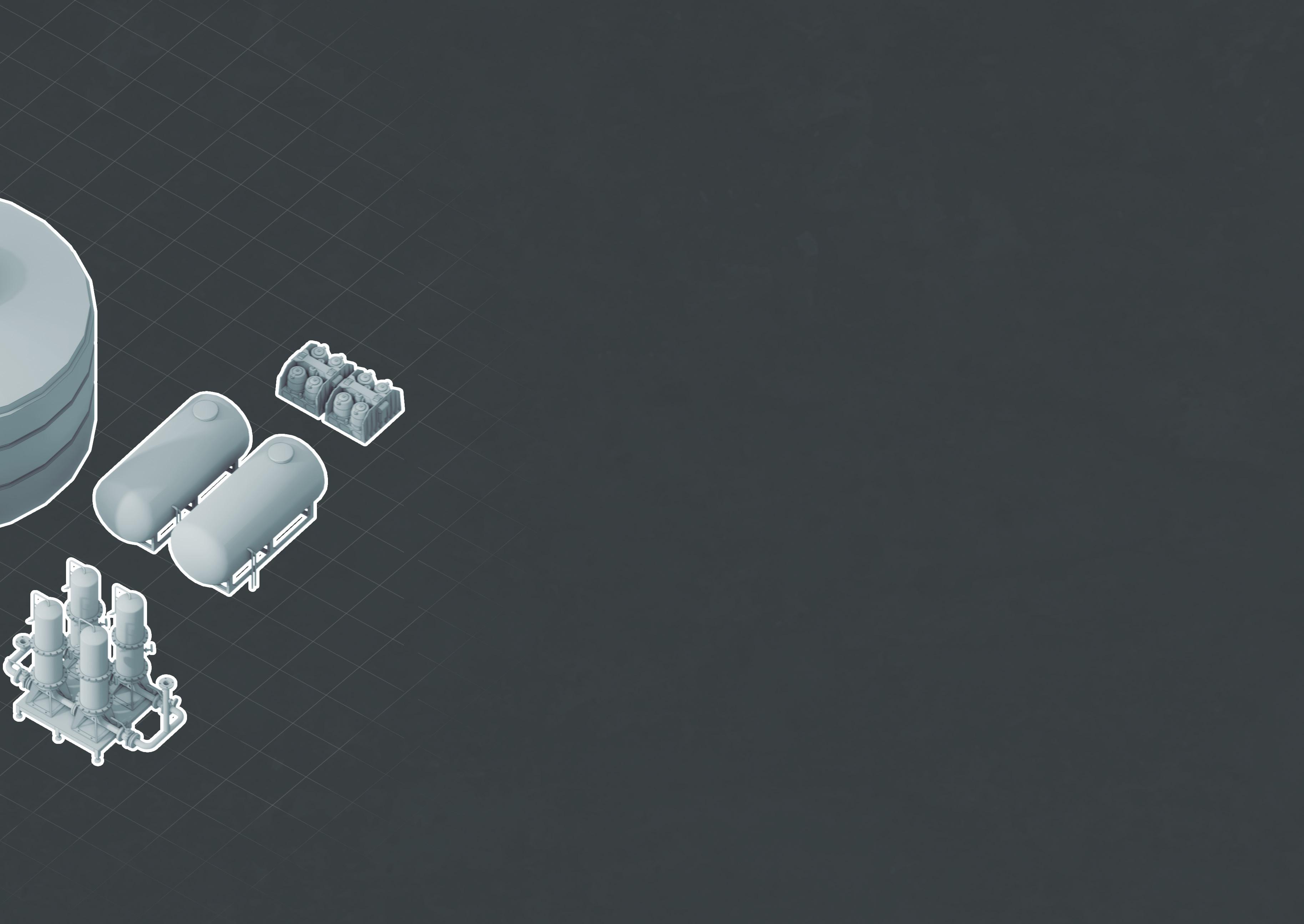
Fermentation Tank
Serving Tanks, Canning & Kegs
Pre-treatment Tank
Separator Tanks
Granular Biomass Reactor
Anaerobic Digester
Exhaust
Lauter Tun
Client & Stakeholders
Client Aims
Client Statement of Intent
Brewing Unplugged: A microbrewery looking to expand their business and audience with a new facility to brew and sell beer[12]

Research Partners
Rothamstead Research: A research centre located in Harpenden, Hertforshire, specialising in Agritech and Bioscience. They have close ties with the BBSRC, one of the funding partners for the project[13]

Ekonoke: A start-up company pioneering sustainable hop production, through indoor vertical farming and a technology driven approach to environmental monitoring and control[14]
Funding Sources
BBSRC: Biotechnology and Biological Sciences Research Council, a subsidiary section of the ‘UK Research Institute’, providing grant funding for scientific projects relating to sustainable crop production and fuel generation[15]

Swindon Council: Providing potential grant funding through innovation grants[16].

The building should act as a manifesto project which promotes a circular brewing process; providing spaces for developing this emerging technology with the intention of exposing these methods to larger brewers in the UK. The building has the opportunity to play a pivotal role in strengthening the local community, enhancing civic pride in the wider redevelopment of Swindon.
Physical Aims
Establish a New Base in Swindon: Create a new facility for Brewing Unplugged, opening their products to a new target market. Beer will be sold on-site in a dedicated taproom and also exported to resellers.
Biohydrogen Technology: Create a suitable facility for developing relevant technologies relating to biohydrogen production, focusing on extraction of clean energy from brewery waste products.
Environmental Aims
100% Energy Generation: The building should produce all of its required power on site, through either Biohydrogen or Solar PV, with associated battery storage. The building should achieve an operational energy demand of <75 kWh/m2.yr in accordance with LETI design targets[17]
Enhancing Biodiversity: The building should enhance local biodiversity as much as possible, alongside its utilisation of hydroponic technologies. Biodiversity net gain must be at maximised across the site.
Social Aims
A Hub for the Community: The building should act as a hub for the community, providing a new public venue for the Old Town community to rebuild around.
Schedule of Accommodation
The Site
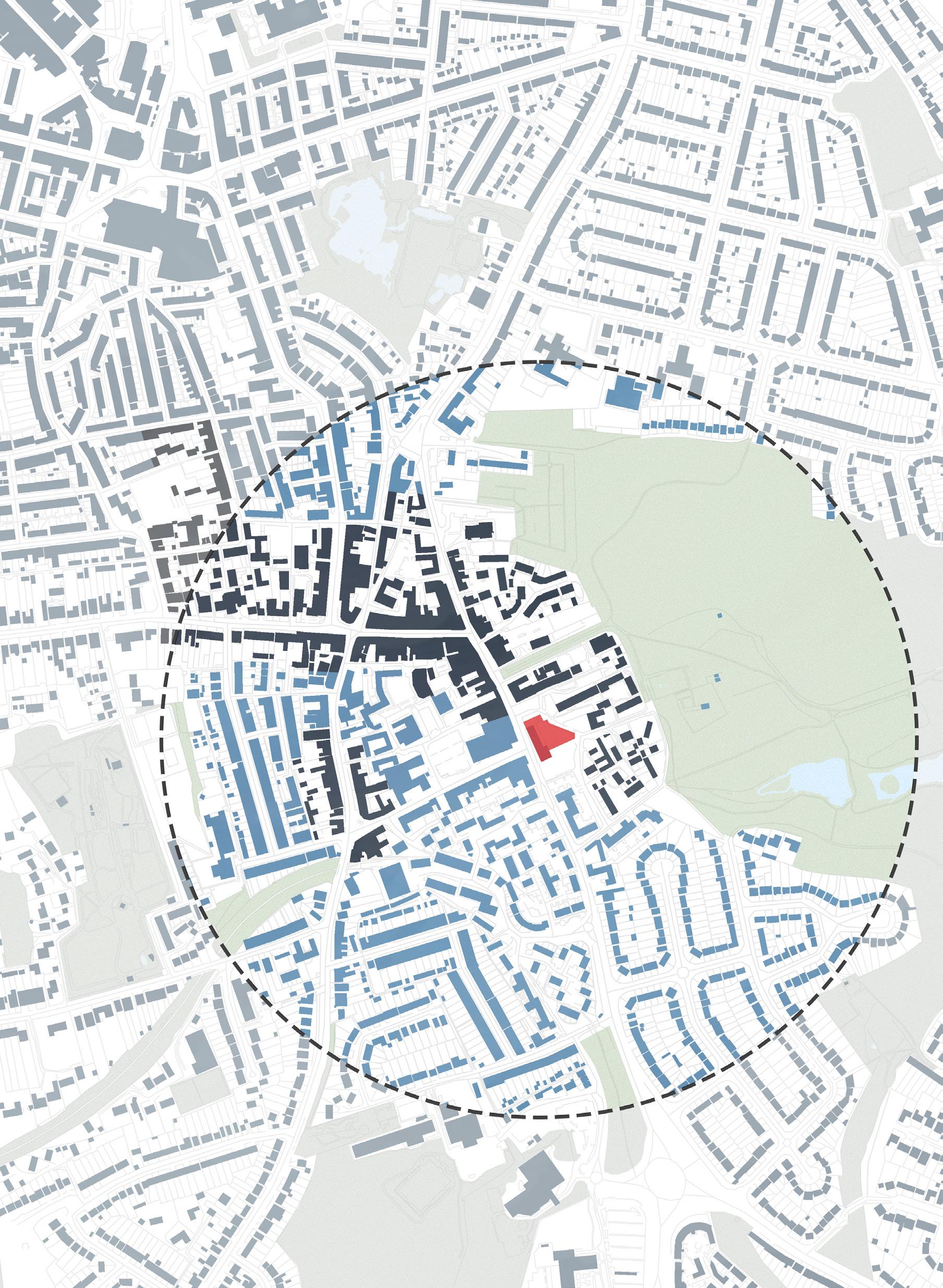
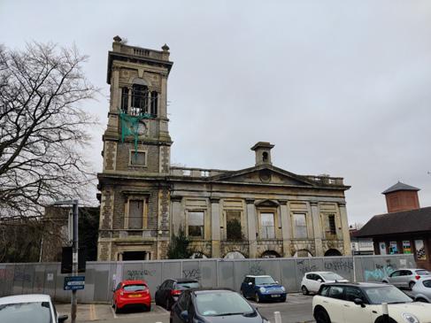
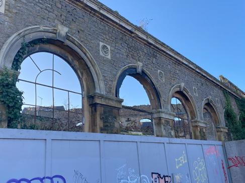
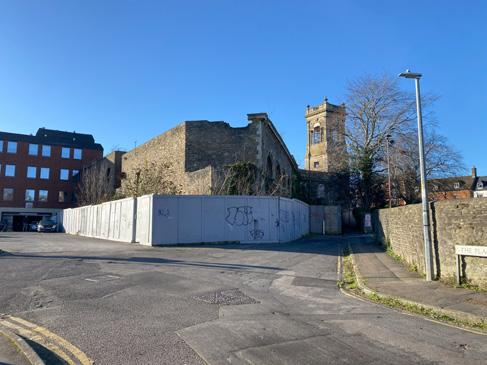
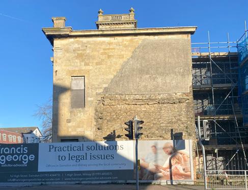
The chosen site is Swindon’s Old Town Hall, a derelict building situated in the middle of Swindon’s Old Town. Built in 1852, the building has a rich history - being used as a town hall, corn exchange, dance hall and later for commercial use[18]. Built from ashlar stone in a Neoclassical style, it is an attractive building which has the potential to act as a centrepiece within the Old Town quarter - a building of architectural quality that reignites Swindon’s civic pride and provides a basis for the regeneration of the wider area.
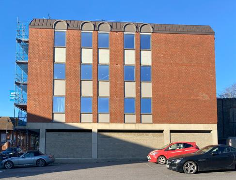
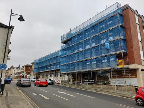
The extent of the site also includes an adjacent concrete framed office block (known as ‘The Forum’), a 4 storey building constructed in the 1980’s with a concrete frame and brick facade. The building is of little architectural merit and detracts from the quality of the adjacent Town Hall. It is built on the site of an older building (built at a similar time to the Town Hall) that was later demolished to allow for road widening works.
Buildings within the Old Town Conservation Area
Buildings outside the Old Town Conservation Area
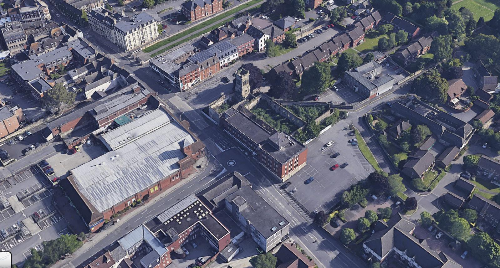
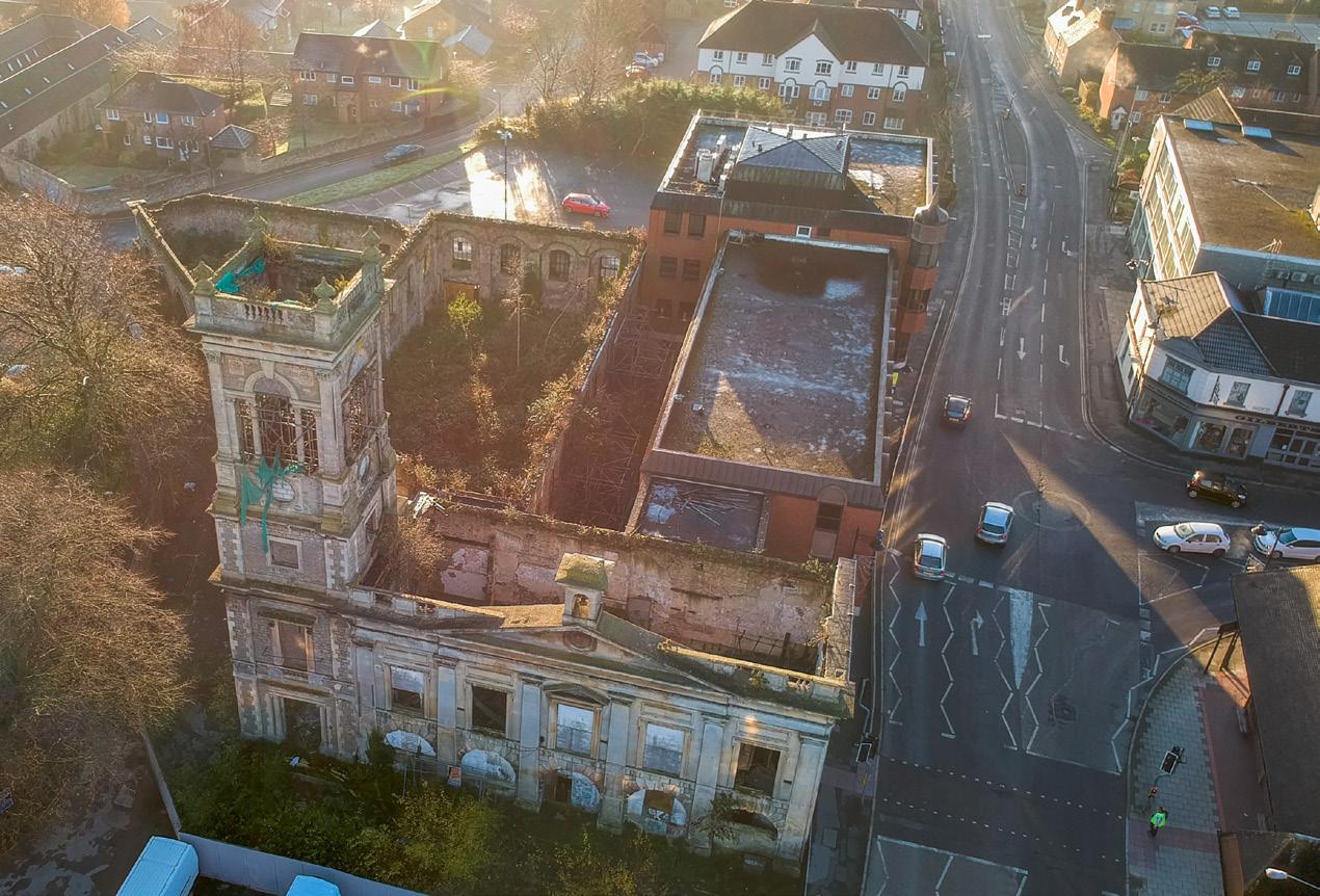 Figure 4: Aerial view of the Old Town Hall
The Lawns
15 minute walk from site
Regents Circus
Old Town Hall
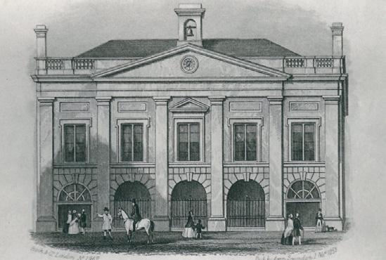
Town Hall built in 1852, serves as a public room with space for 600 people; used for public meetings, balls, lectures and meetings. It was also designed to provide accommodation for the County Court[19]
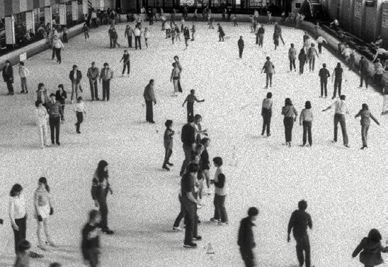
Swindon’s new town hall was constructed in 1891, with the Old Town Hall becoming briefly redundant at this time. Following this, it was renovated into a 1000 seat theatre, an ice rink, and later a cinema[21]
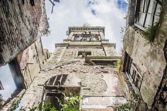
The now Locarno Hall was subject to two fires (in 2002 and 2004) which left the building gutted, without a roof and in a poor state of repair. It is currently vacant[22]

In 1865 the building was extended to the South and East to form a corn exchange; works which included an 80ft tower and a triangular market hall covered by a glass dome[20]

The building was refurbished in 1949 to become the Locarno Dance Hall, hosting music concerts and wrestling events[35] The adjacent road facing building (which contained a pub and commercial units) was demolished in the 1970’s to make way for road widening works, with the new ‘Forum’ building constructed in its place.
Environmental Analysis
Sunpath
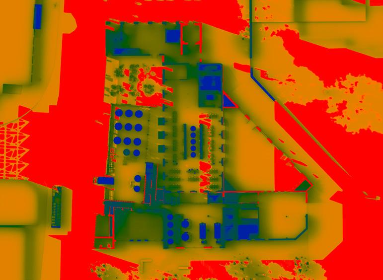
With the empty car park to the South and low lying buildings to the East and West, the site benefits from good sun with little overshadowing. Solar gains will need to be managed.
The main prevailing wind is from the South West, although given the built up context this is not always consistent. The strong prevailing wind will facilitate good passive ventilation.

Noise & Pollution
The main road to the West is the main source of noise and pollution across the site, with little present elsewhere due to low levels of activity.

Pedestrian & Vehicular Routes Levels
The main vehicular routes run to the West of the site, with pavements adjacent. The ‘cut through’ along Dammas Lane to the East is the only dedicated pedestrian route.

Building Heights
Typically low lying one and two storey buildings, with 3 stories maximum to the North and West of the site.

The site falls away to the South, resulting in a consistent level change of approximately 1m.

Active Frontages
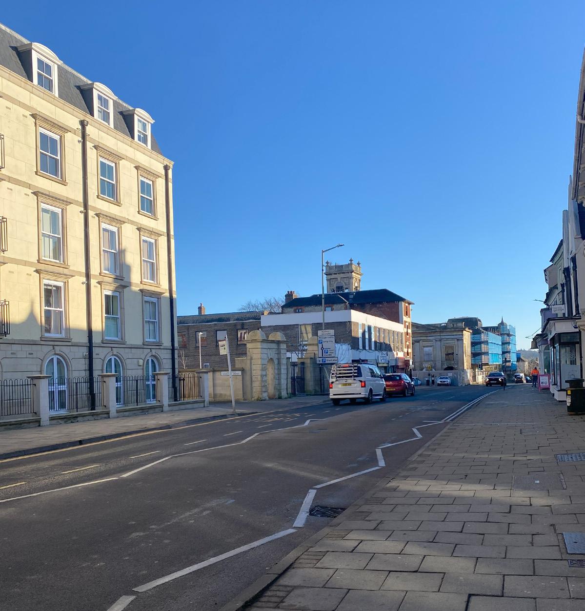
Surrounded on all sides by urban fabric and pedestrian routes, it is key that the proposal responds to the varying activity levels present on each of the existing façades, which will ensure a contextual response is achieved. The diagram to the right grades each facade relatively in terms of existing activity, highlighting a gradient from West to East. Facing onto the main road, the West facade is the most active and forms a bookend to the East end of Newport Street. On the other end of the site, the facades furthest East - most notably the South East facing facade facing onto The Planks - has extremely low activity; the only movement being a few locals who use the car park.
It is worth remembering that whilst not all these facades are considered ‘active’, they do all play prominently in the view cones on approach to the site - especially the North facade and the existing bell tower.

MEDIUM
The Historic Context
The Old Town Hall has a rich history; built in 1852 and having a range of uses until present. It was gutted by two fires in 2002 and 2004 which left the building as a vacant shell with no roof, and it has been abandoned since[23]. The square in front of the Town Hall (to the North) was previously used as a both market square and as a terminus point for Swindon’s historic tram network[24]
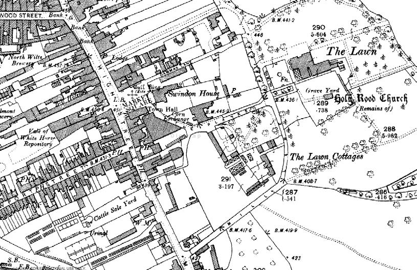
In terms of the wider context of Old Town, over the past ~170 years the urban environment has both changed drastically but also not changed all that much at all. The sequence of maps below help to detail these degrees of change.

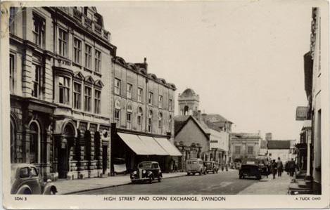
1880’s
The fabric of Old Town to the North is somewhat resemblant of that today, however in all other directions the context is mainly unrecognisable. The Planks is a much more active route, and leads to Holy Rood Church set in the Lawns. Swindon House sits adjacent to the Corn Exchange to the East, and a collection of buildings sprawl around the Old Town Hall to the West. Note the established route running East to West, cutting through to the South of the Corn Exchange.
1970’s
The urban grain of Old Town remains similar until the 1970’s, where historic maps show a host of demolitions to the West and South of the Old Town Hall, as well as the demolition of Swindon House and the buildings to the West (which are replaced by what is now a supermarket).
The Old Town hall sits much more on an isolated island than before, with little context in the immediate vicinity.
Ground Conditions

0.00m - 1.75m Made Ground
Principally brick fragments, ash and other old demolition waste
1.75m - 8.10m Kimmerage Clay
Sedimentary deposits of fossilferous marine type clay & mudstones.
8.10m - 18.3m Portland Sand Bed
Lithified deposits of finely crystalline sandstones and siltstones.
18.3m - 19.8m Limestone
Thin limestone bed
19.8m -> Kimmerage Clay
Sedimentary deposits of fossilferous marine type clay & mudstones.
Design Drivers
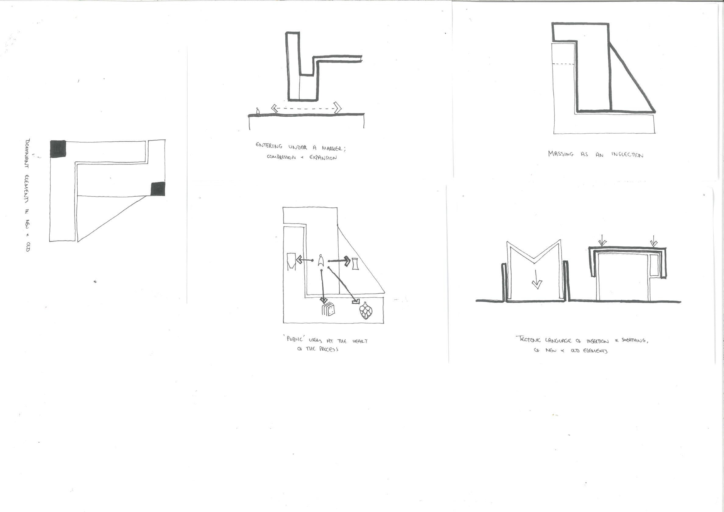
Placing the Public at the Heart of the Process
In line with the wider aspirations of the building, the industrial and manufacturing processes are exposed to the public elements of the building; blurring the boundaries between served and service.
A Nexus for the Community
The building is a permeable entity, with active frontages to all sides and several entrances. With the myriad of pedestrian routes that pass around the site, the proposal responds to the various approaches around the site.
A Clear Distinction between New and Old
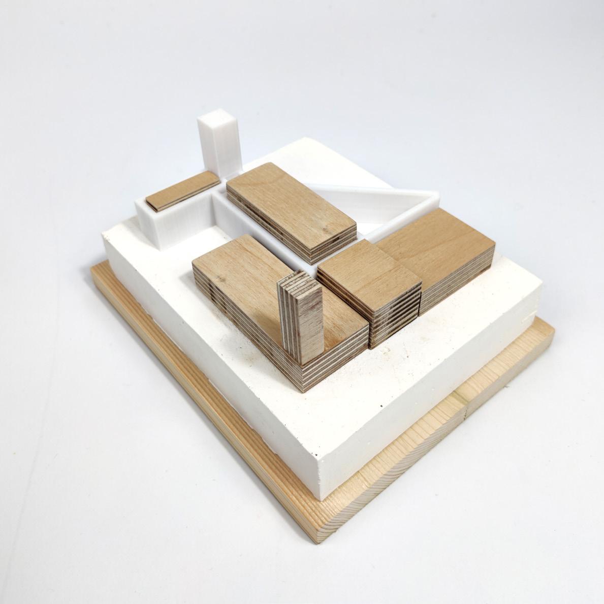
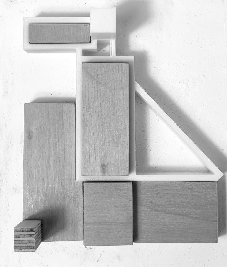
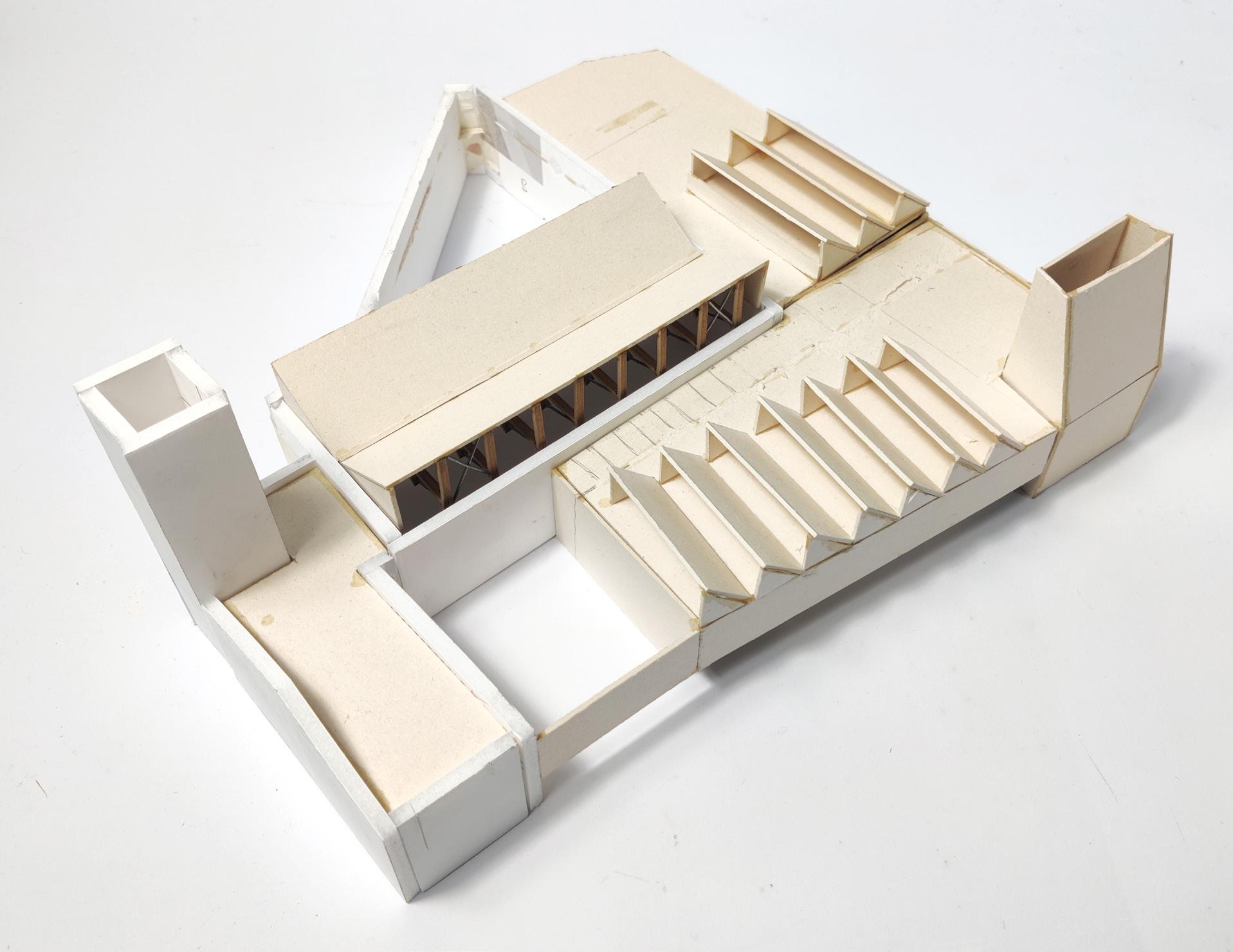
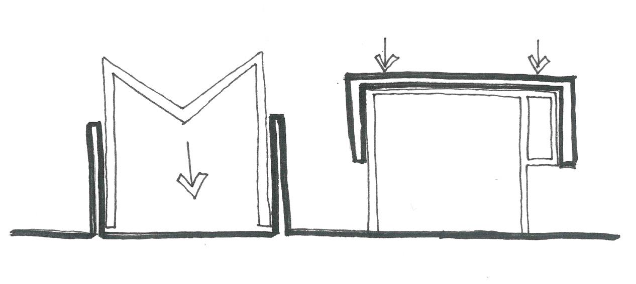
The layout, massing and materiality of the proposal respects the existing building, with a clear distinction between new and existing elements. The overarching concept of ‘massing an an inflection’ has been integrated, with the new elements referencing back to the existing building.
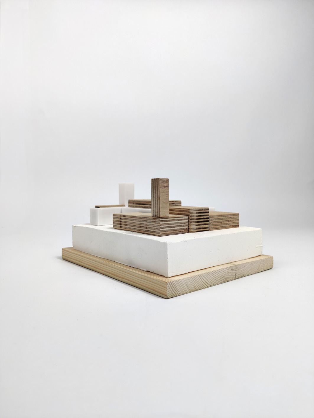
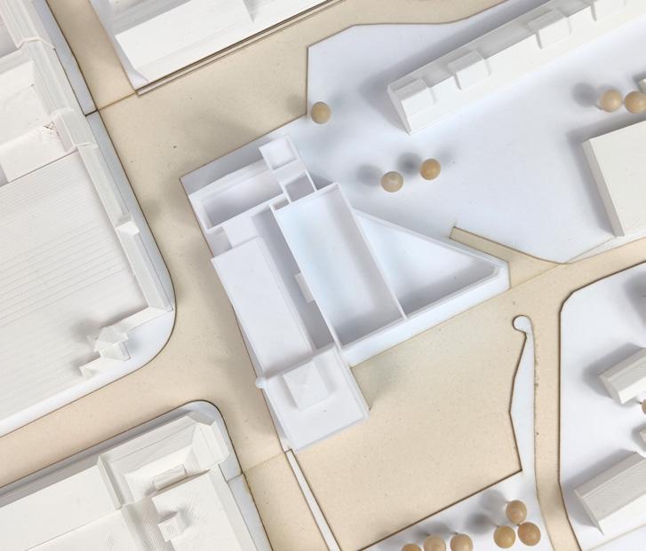
Concept model exploring the idea of massing as an inflection
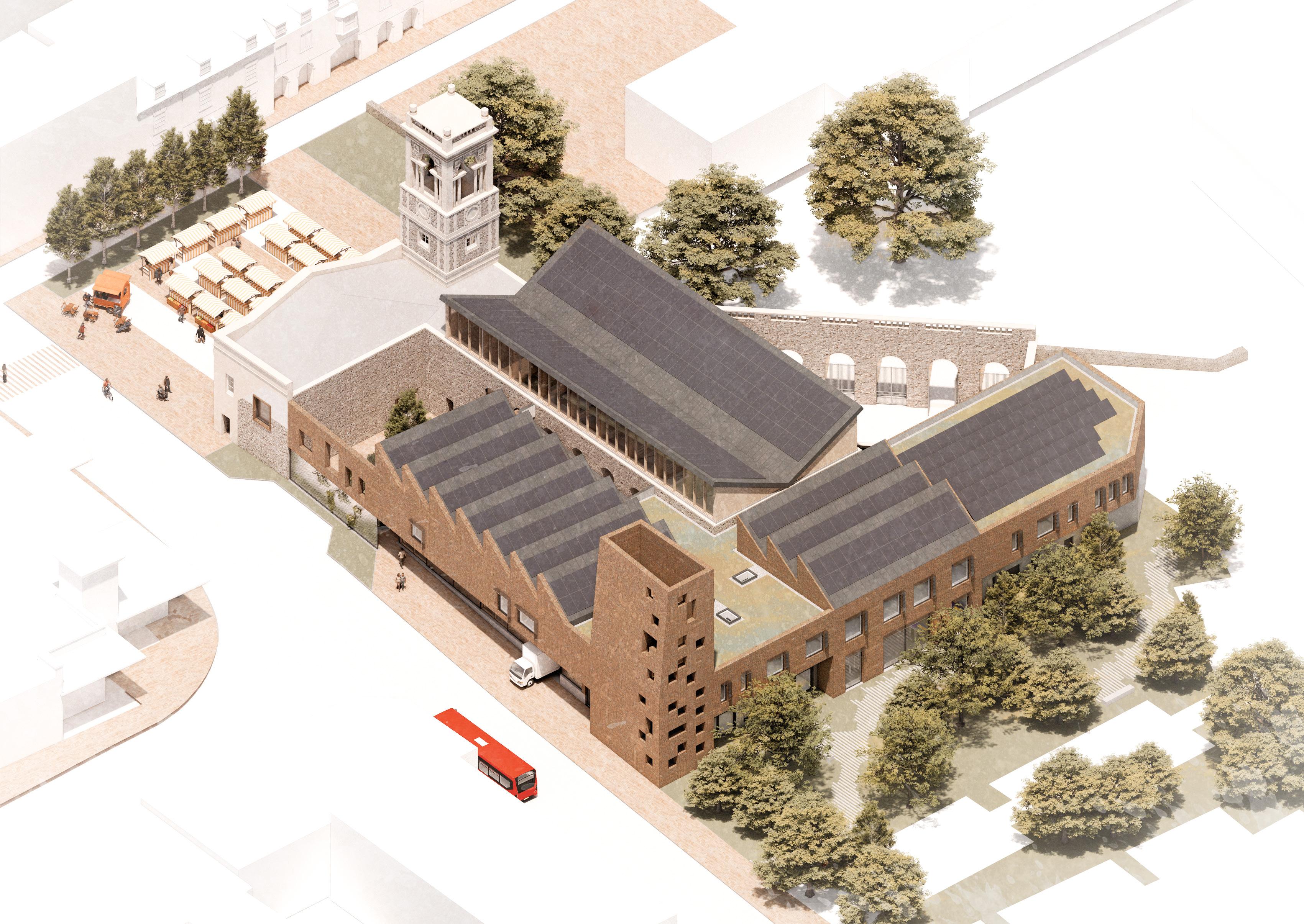
Massing Strategy

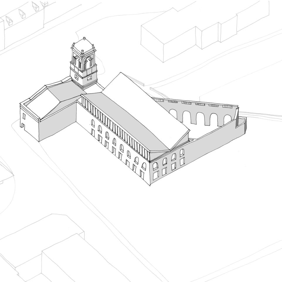
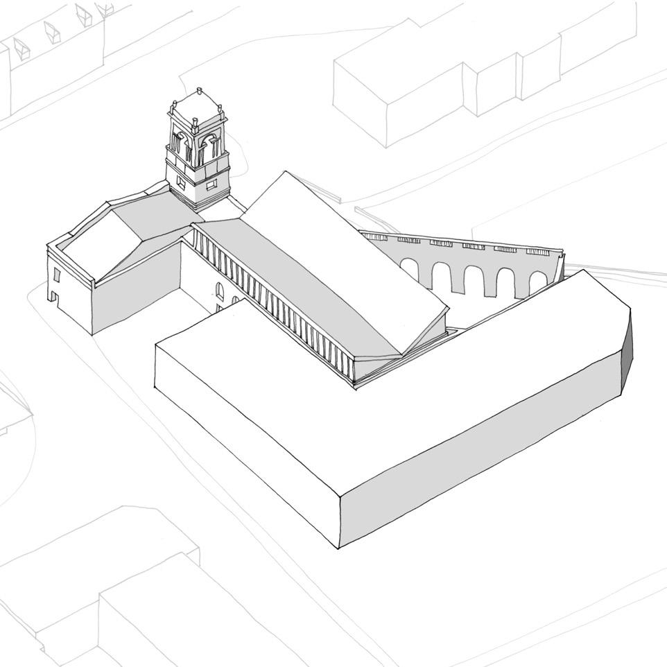
Existing 1970’s office block (‘The Forum’) demolished. Materials salvaged and retained to be reused within the new proposal.
New trussed butterfly roof structure and mezzanine inserted into existing Corn Exchange. Continuous clerestory added to East and West elevations between the underside of the new roof, and top of existing wall.
New massing proposed to South and West of existing building, with the extent of massing to the South informed by historic plot boundaries. Massing stopped short of the existing Town Hall to form a courtyard and allow the existing building to breathe.

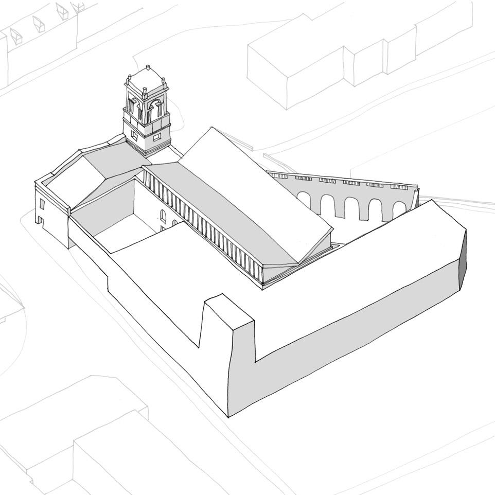
The elevation to the West is skewed to align with adjacent road edge, maximising the active frontage and meshing the building with the public realm.
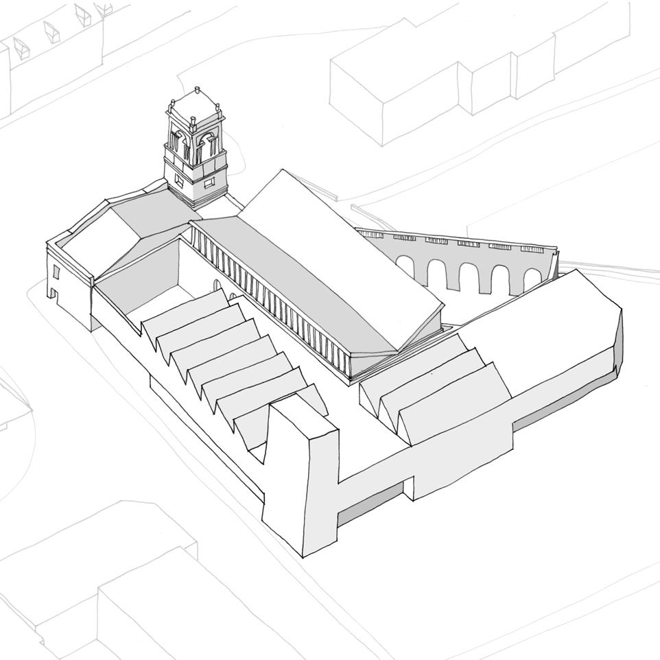
New tower added to South West corner to anchor the new massing, acting as an inflection of the existing bell tower to the North. The new West facade at first floor level is extruded to abut the existing Town Hall building, providing enclosure to the new courtyard.
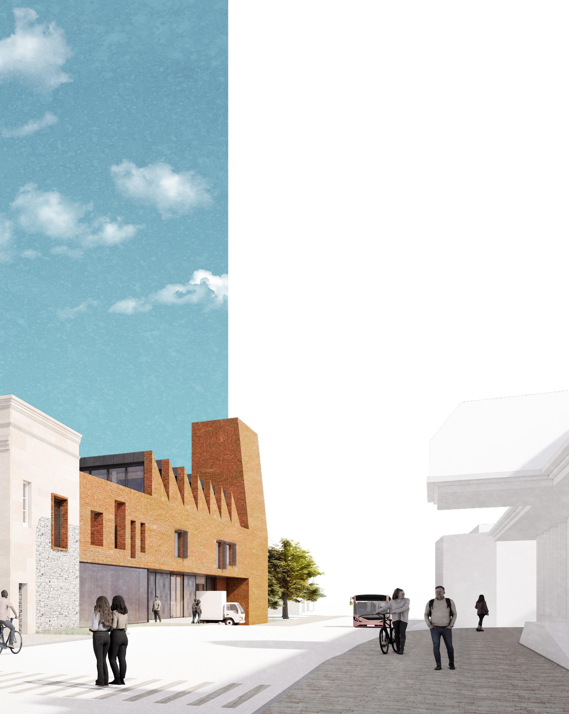
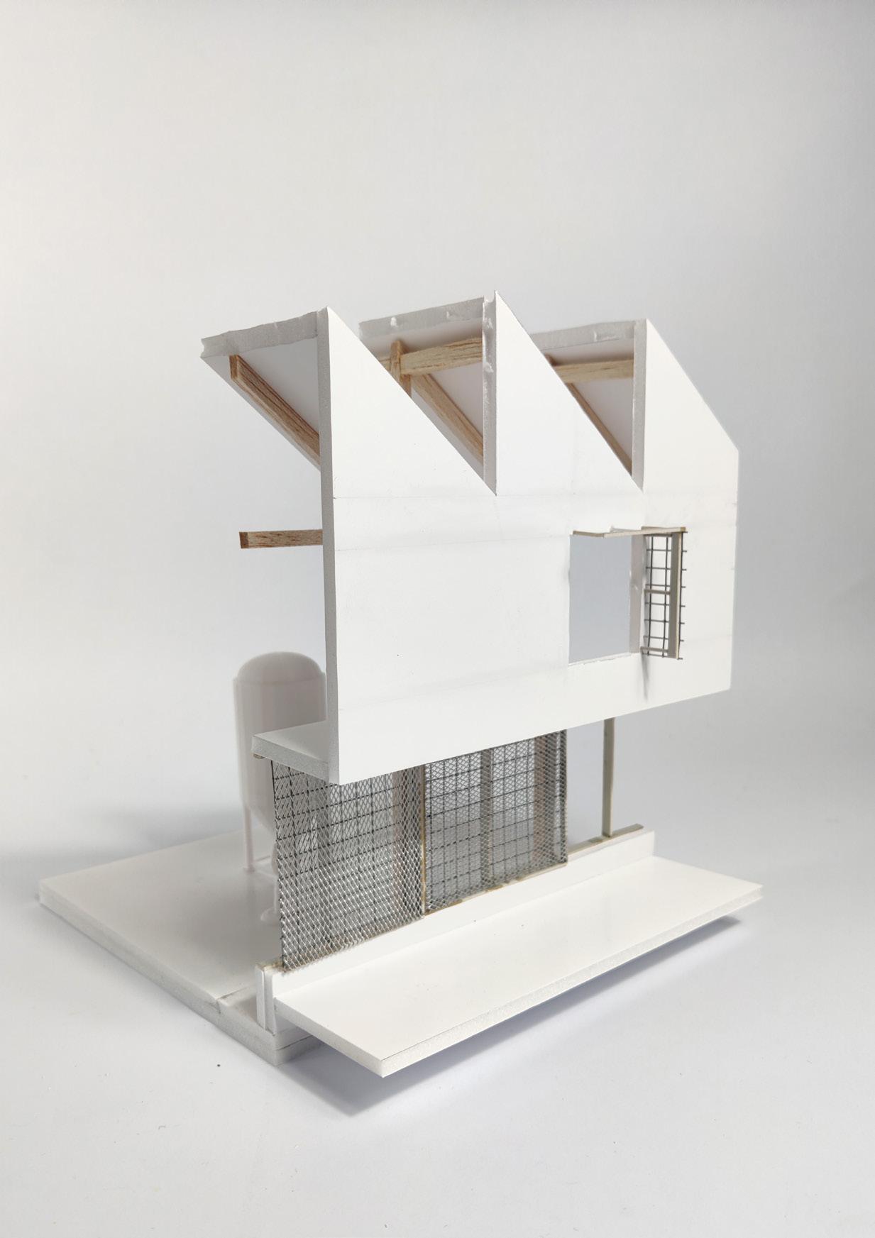
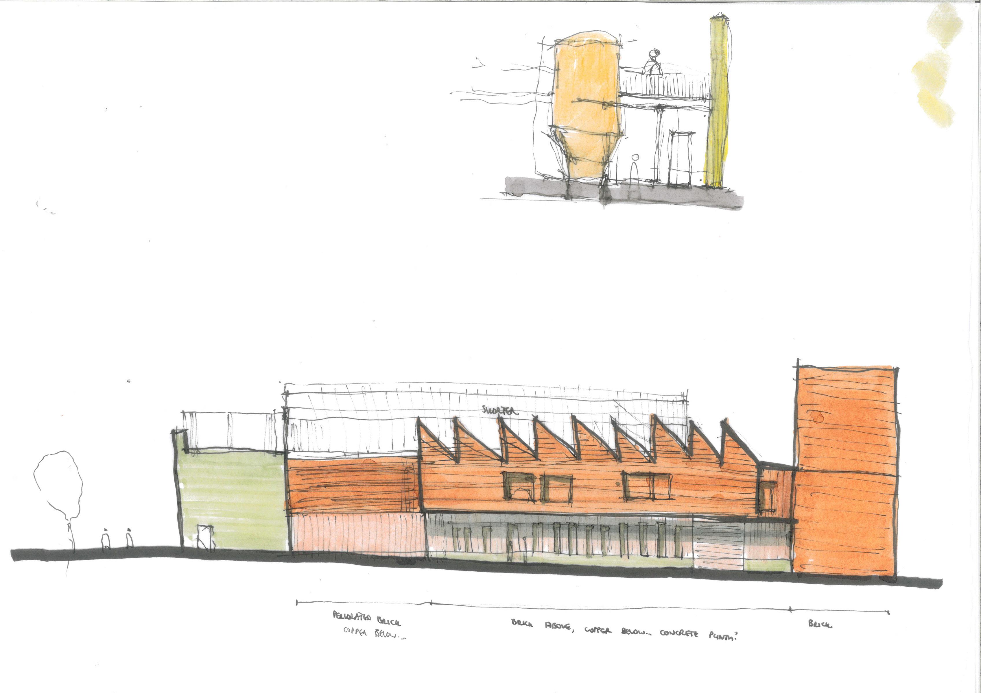
Sections of the Ground Floor are recessed to add vertical emphasis to the new elevations and further reinforce the solidity of the new tower. Sawtooth roof planes are added over key spaces (the brewing hall and labs) to provide North light and break up the flat roof plane.
Proposed Demolitions
A Necessary Evil
With embodied carbon a crucial discussion point in the current climate crisis, demolition is something which should typically be avoided - it is naturally wasteful, with little opportunity given to old materials for a new lease of life. In the present climate situation, adaptive reuse should be prioritised; making the most of existing buildings and extending the lifespan of existing structures and materials.
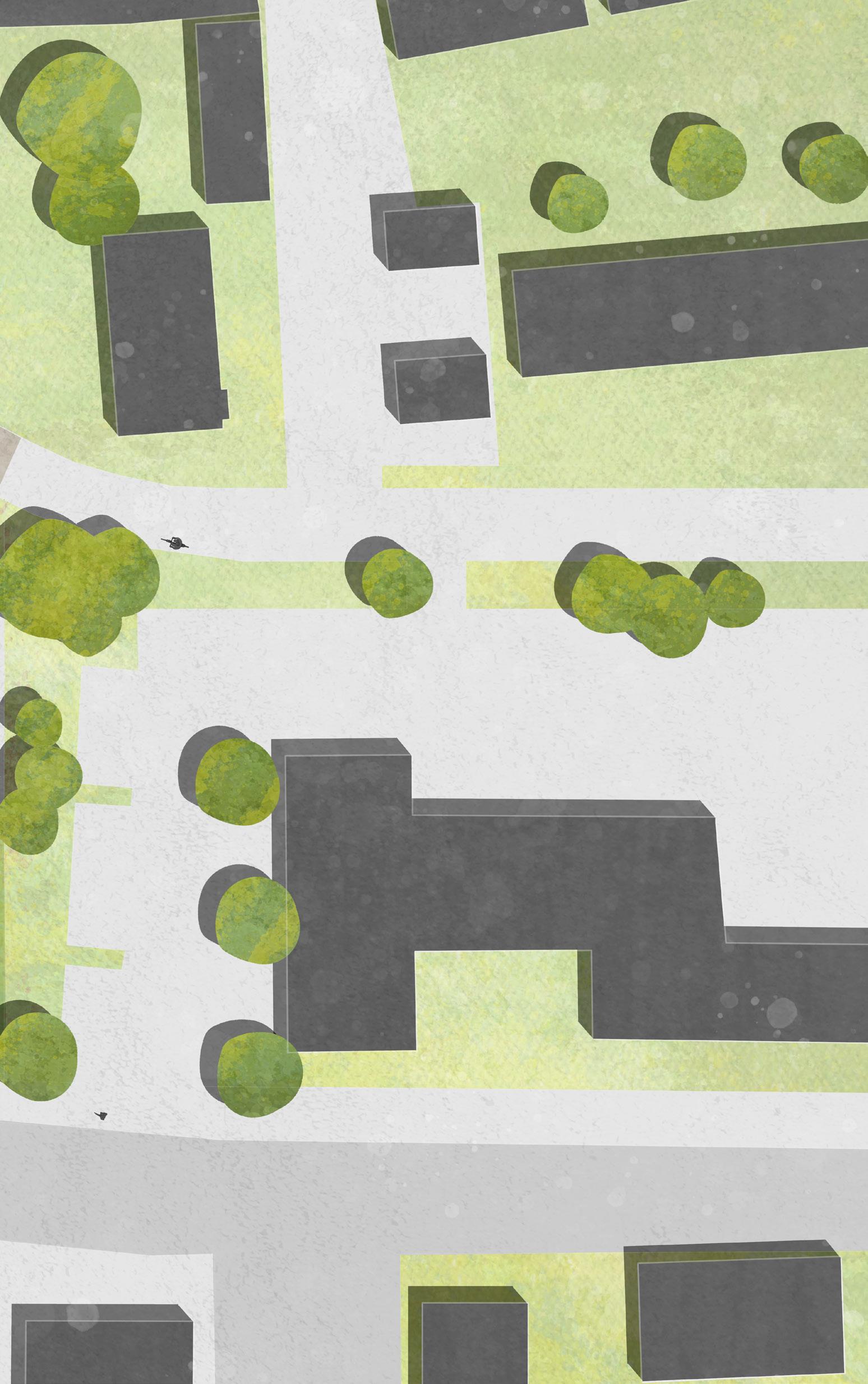
Given the above, it may be ironic that demolition is proposed as part of this project; the removal of an existing 1970’s concrete framed office block which sits in the direct context of the Old Town Hall. At approximately 55 years old and currently vacant, the building is likely coming to the end of its design life. And, frankly, as an ugly example of 1970’s architecture, it has a detrimental impact on the Listed Old Town Hall; its massing poorly considered and its façades leaving a lot to be desired.
A Dialogue of Reuse
With demolition necessary to maximise the potential of the project and more effectively begin the regeneration of the wider area, the discussion now turns to how best to deal with the materials generated from the existing building. Rather than taking the (sadly) all too typical approach of carting away to landfill, the project sees the existing building as an opportunity - a kit of parts which can be repurposed in this new project. This creates a very visible dialogue of reuse; pushing the history of the site to the forefront in the language of the new proposal. And by repurposing old materials in new ways, the building hopes to act as an exemplar project to push the potential of material reuse across the wider construction sector.
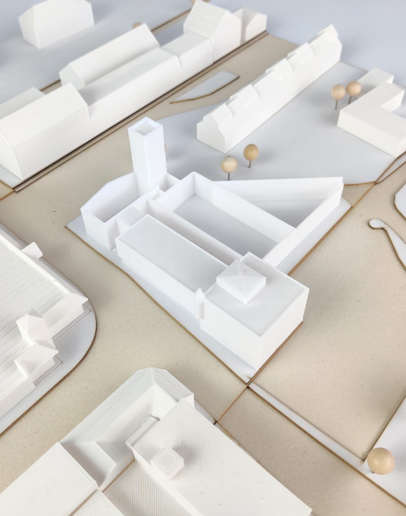
1:500 existing context model showing extent of demolition
The Kit of Parts
Materials gained from demolitions - All values are approximate.
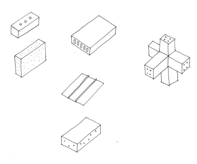

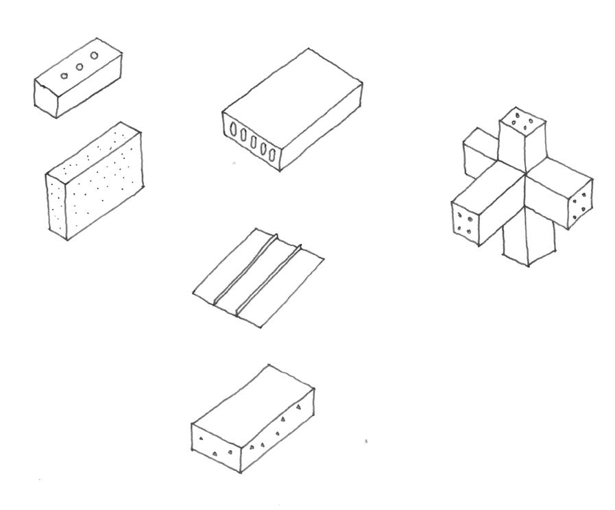
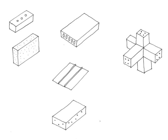
There are also miscellaneous floor finishes, fittings etc. which could be salvaged and reused but cannot be quantified, and so are not shown.
Healing the Fractured Fabric
Old Town is currently a fractured community, where multiple urban grains, architectural languages and masterplanning typologies clash. There is little identity or civic pride for the people living here; no large scale public interventions where regeneration efforts can take shape.
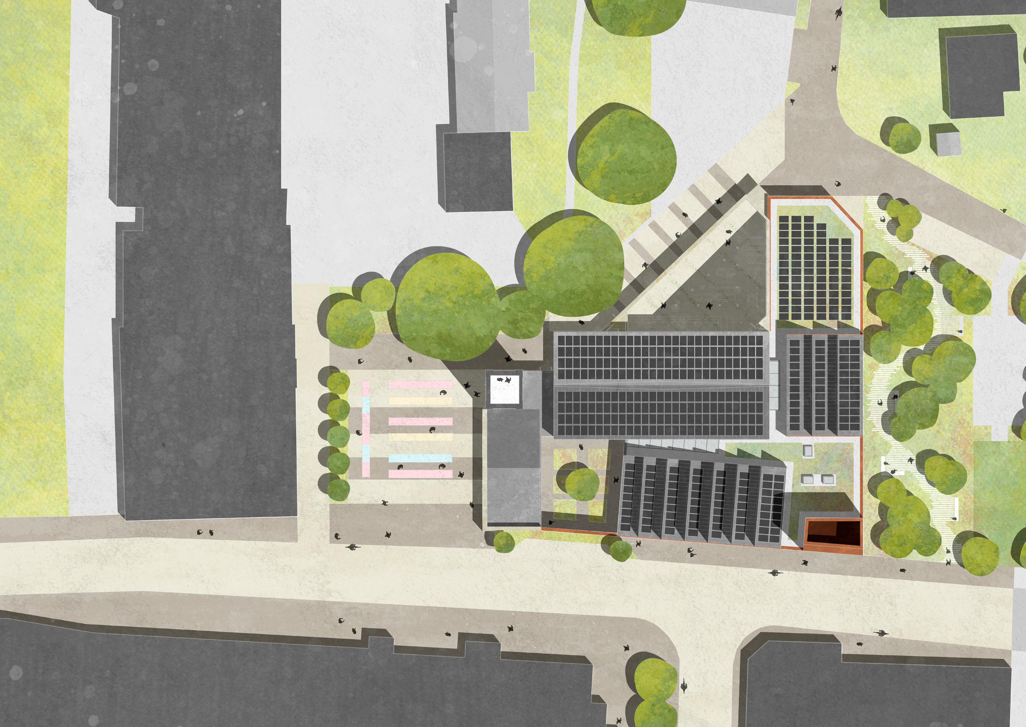
The proposal aims to provide just that - a new public building which the community can rally around and from which they can draw new civic pride. In a masterplan context, the building achieves this focus by:
Providing a key public building within Old Town, which acts as a focal point for the community to draw people together.
Reinstating a connection to The Lawns, the public space to the East of the site, by focussing efforts on activating Dammas Lane and The Planks.
Providing a ‘bookend’ to Newport Street, which is currently a long and boring street with little architectural interest and which gives people little reason to walk along it.

1:500 context model showing the proposed scheme

The Users
Public
Jamie
A tourist visiting Swindon with his wife on a long weekend. They came across the building on social media and planned to visit.
They explore the exhibition after wandering through the street food market outside.
Sit in the lively taproom with some drinks.
Watch a fermentation tank being filled with recently mashed & boiled liquor from the observation deck adjacent to the taproom.
Toby
A student studying biomedical sciences at Swindon’s newly opened university institute. He is meeting a date for dinner.
After exchanging an awkward hug, they head upstairs to the restaurant via the bell tower.
They enjoy a meal in the restaurant, located on a mezzanine overlooking the taproom below.
After dinner, they head down to the beer garden.

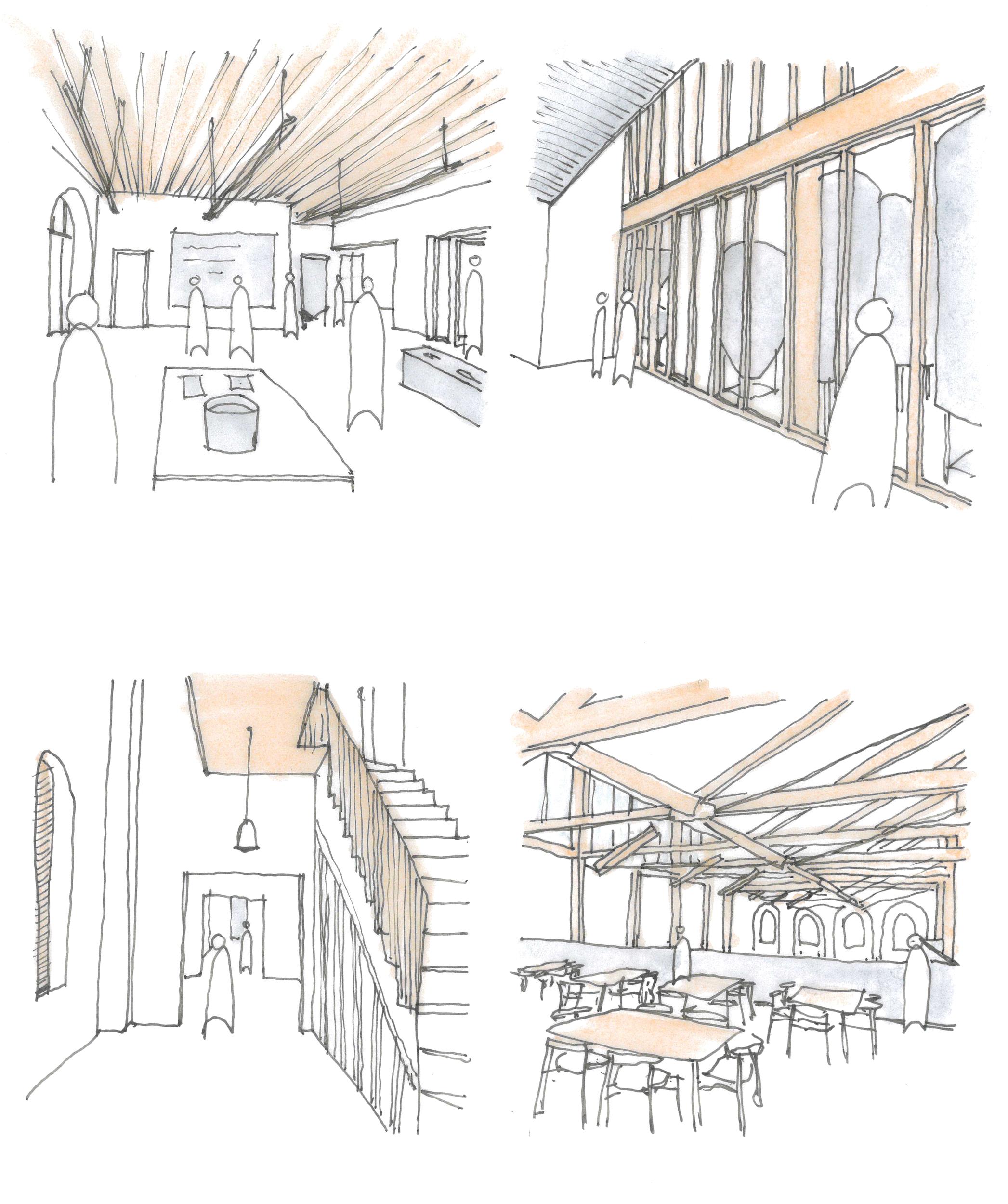


A local Swindon resident and beer lover, he is the co-founder of the brew club which occupies the top floor of the Old Town Hall.
He arrives early to the weekly group meet and heads upstairs via the bell tower.
After setting up and waiting for the group to arrive, he begins brewing an experimental beer using site grown hops and waste products from the restaurant.
As part of their meet, they sit in on a seminar from Hoplex, a brewing equipment supplier.

A recently graduated arts student who enjoys photography. She has spent her afternoon at The Lawns and passes the building on the way home.
Walking back into Old Town via Dammas Lane, she sees a friend in the beer garden and stops to say hi.
She heads inside to the taproom to grab a drink and order some food to her table outside.

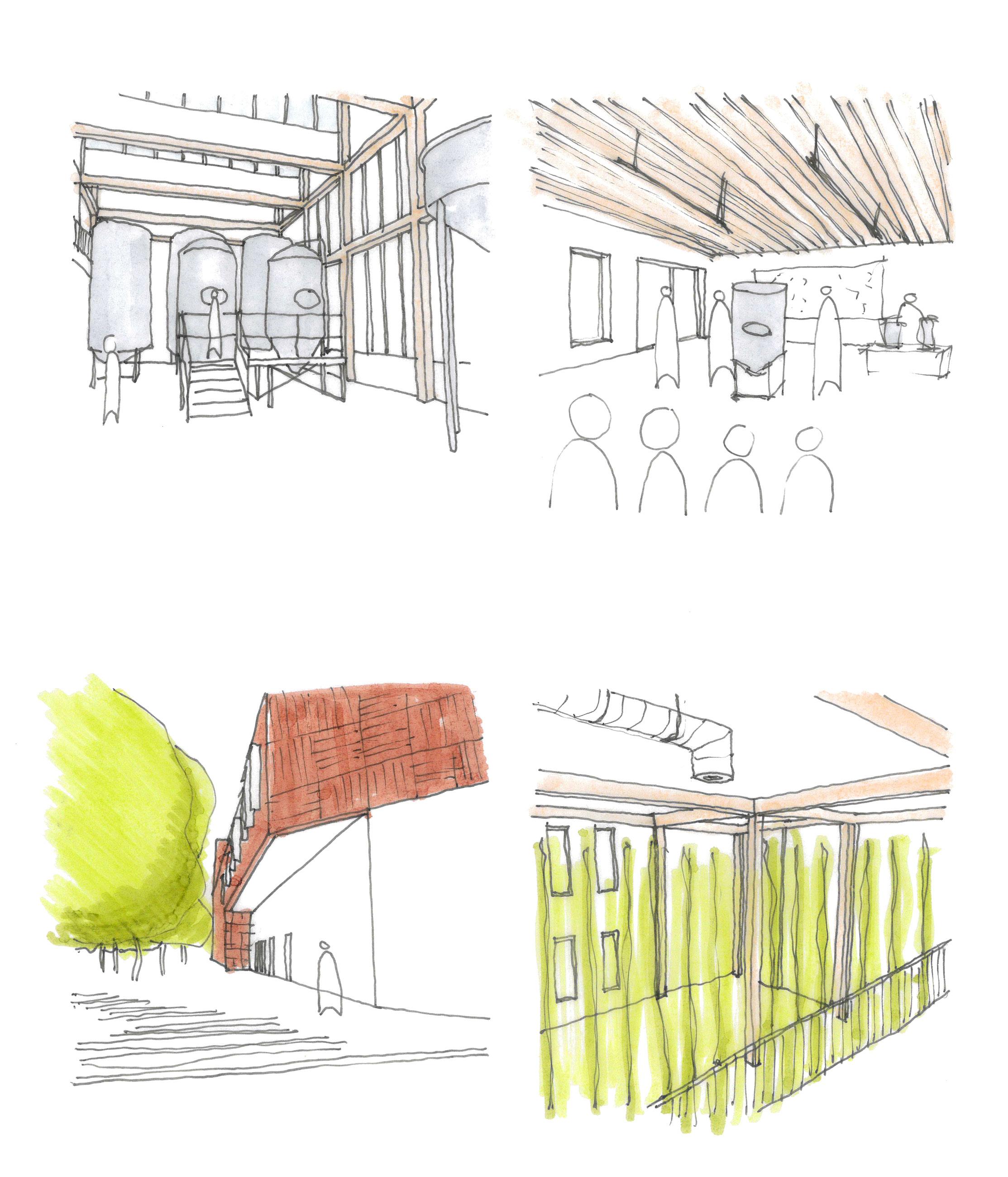


The Users
The managing director of Hop[e] Brewing, he is a keen beer lover and computer science graduate.
He checks general stock levels in the storeroom after receiving a new delivery.
Starts on a new batch of gluten free grapefruit IPA to sell at a nearby beer festival.
Attends a seminar from Hoplex, a brewing equipment supplier, where he bumps into Tom.
Heads upstairs to complete some admin tasks, then shower and change before heading home.

A hydroponics technician with a keen interest in growing climate resilient crops.
She arrives and greets her colleagues before changing into her PPE.
Tends to the rows of hydroponically grown hops and monitors environmental conditions using special probes trained on a bespoke machine learning algorithm.
Packages a new harvest of hops and sends them down to the storeroom


Holly
A biologist studying at the University of Bath who joined Hop[e] on a work placement, and works in the labs developing low carbon pre-treatment solutions for spent grain waste.
She arrives and changes into her PPE, asking Liv about a concert she visited last night.
Continues compiling her current research paper on the use of CRM treatment and starts a series of samples in a stability chamber.
Helps troubleshoot a fault in one of the three anaerobic digesters.
Kieran
He arrives for his evening shift and changes into his uniform before heading to the kitchen.
Completes his prep for the coming shift and runs an inventory check in the storeroom.
Works in the finishing kitchen to plate and serve orders sent up from the main kitchen below.


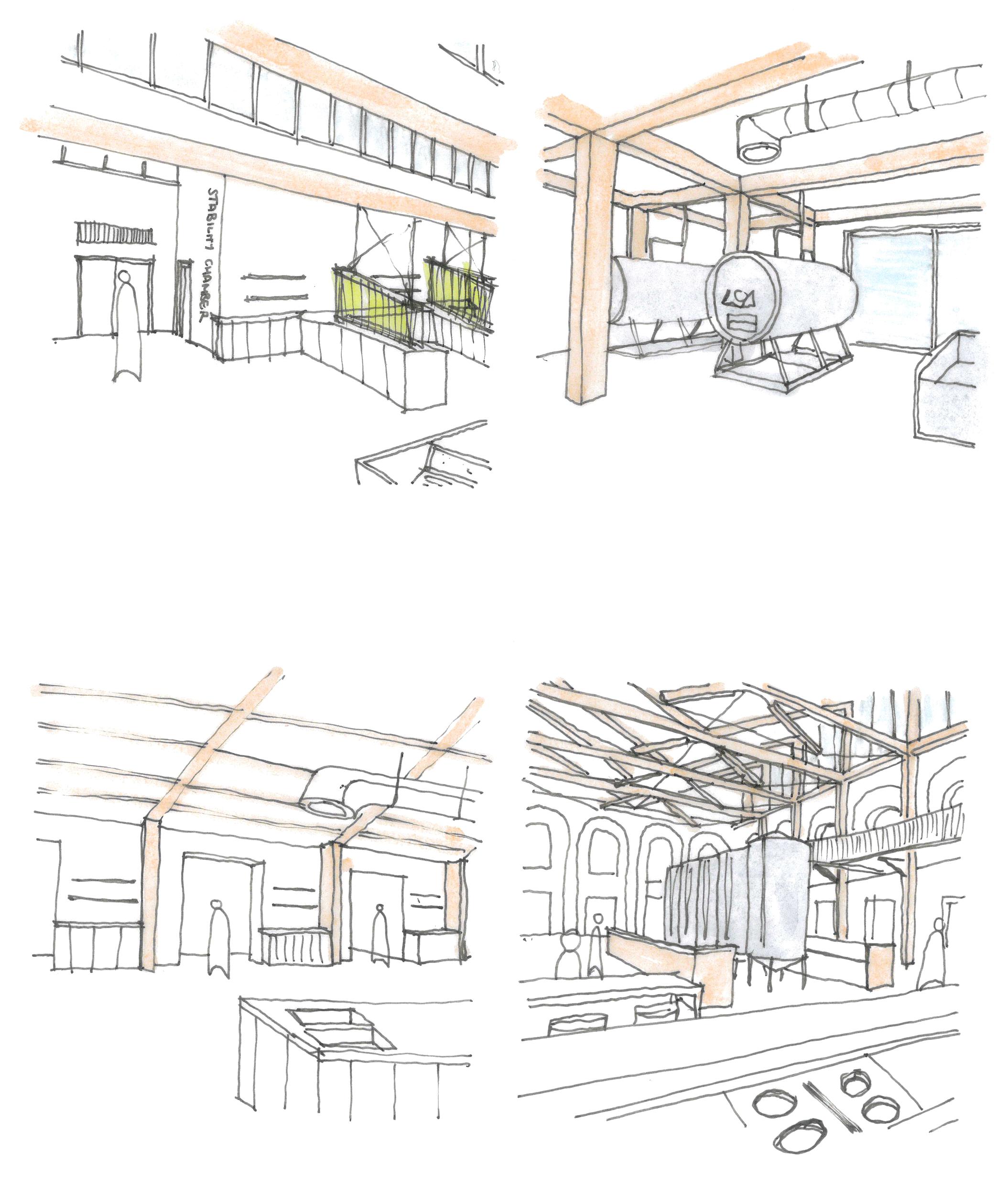


Arrival
With the building sat on an ‘island’ surrounded by both urban fabric and pedestrian routes, there are several ways in which the proposal can be both approached and experienced. Each is curated and unique, with users discovering new hubs of activity or spots of calm as they move through the site.
From the standpoint of a public user, the building and surrounding public realm can be approached, explored and entered from one of three ways:
The North: Approaching from Old Town via the High Street; experiencing the Northern square and entering through the existing bell tower.
The East: Approaching via The Planks and heading up Dammas Lane; the building reveals itself over the tall existing wall enclosing a lively beer garden.
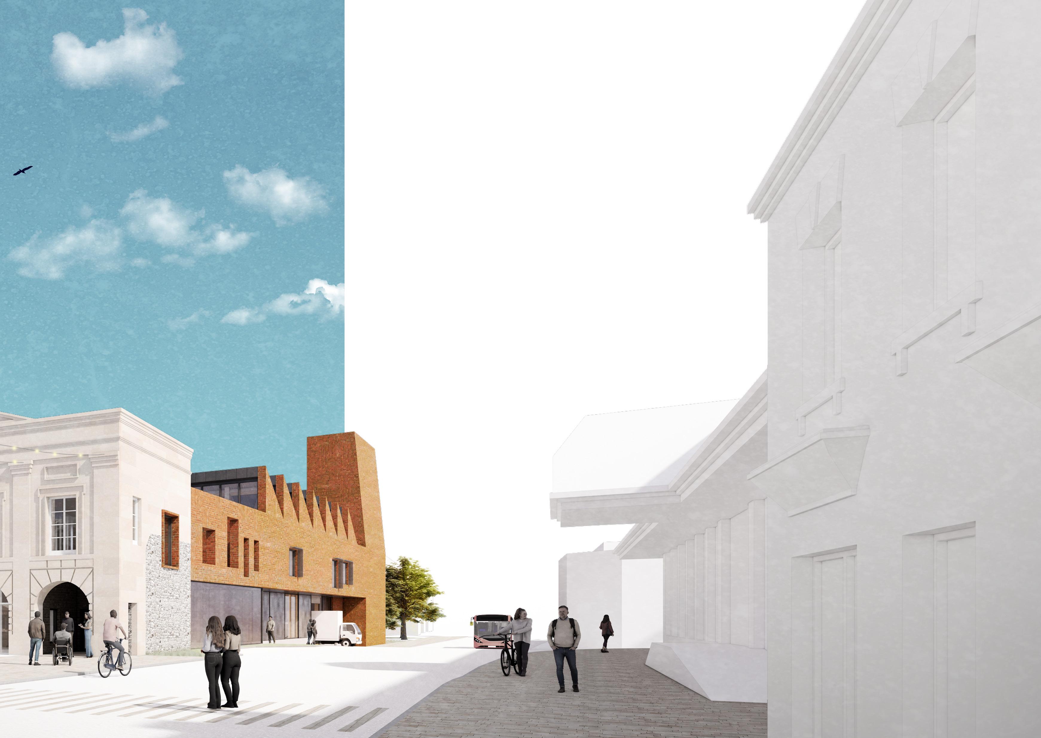
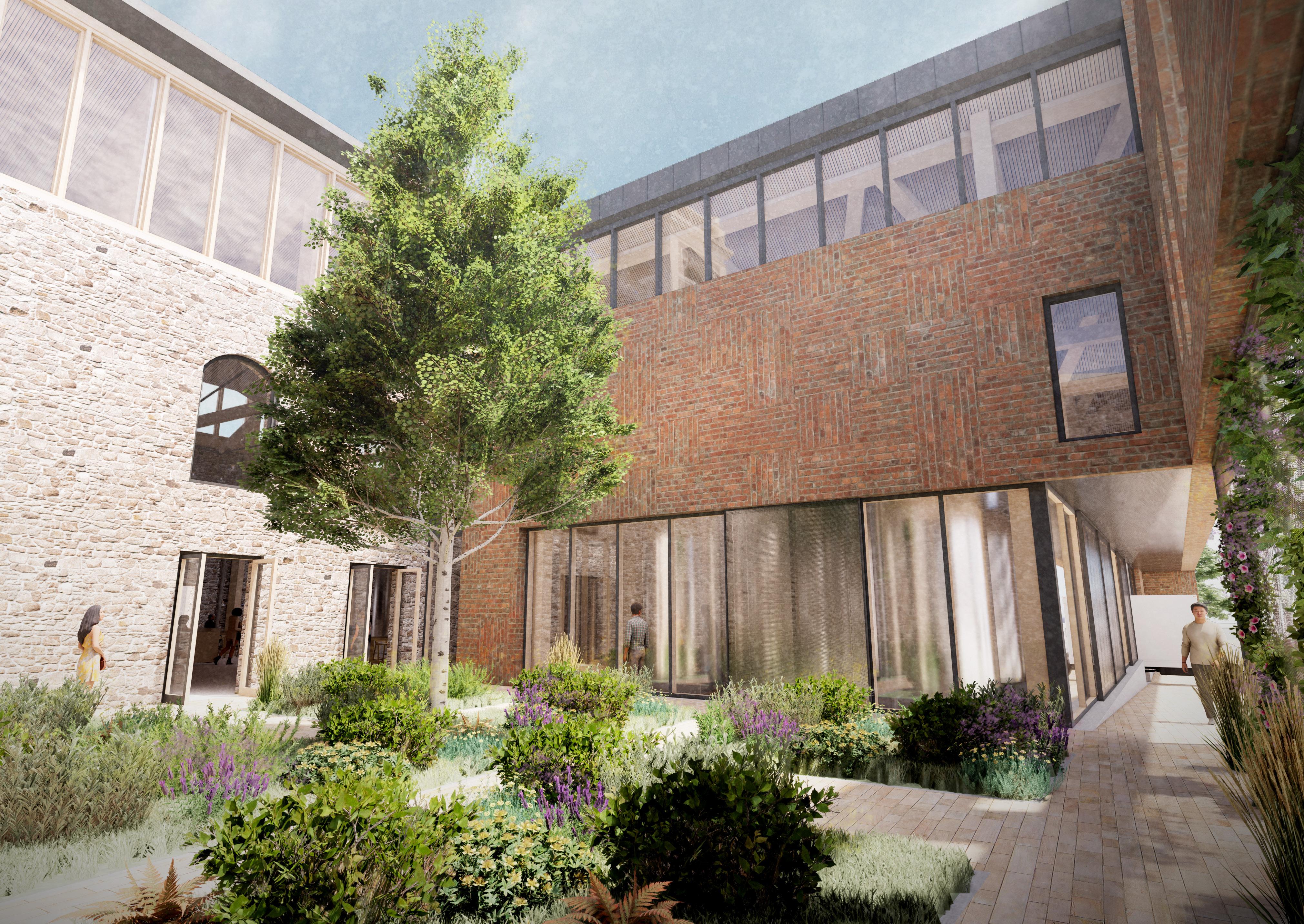
The South West: Approaching along the widened pavement and looking into the double height brewing hall, users are guided into a peaceful courtyard screened from the busy road.
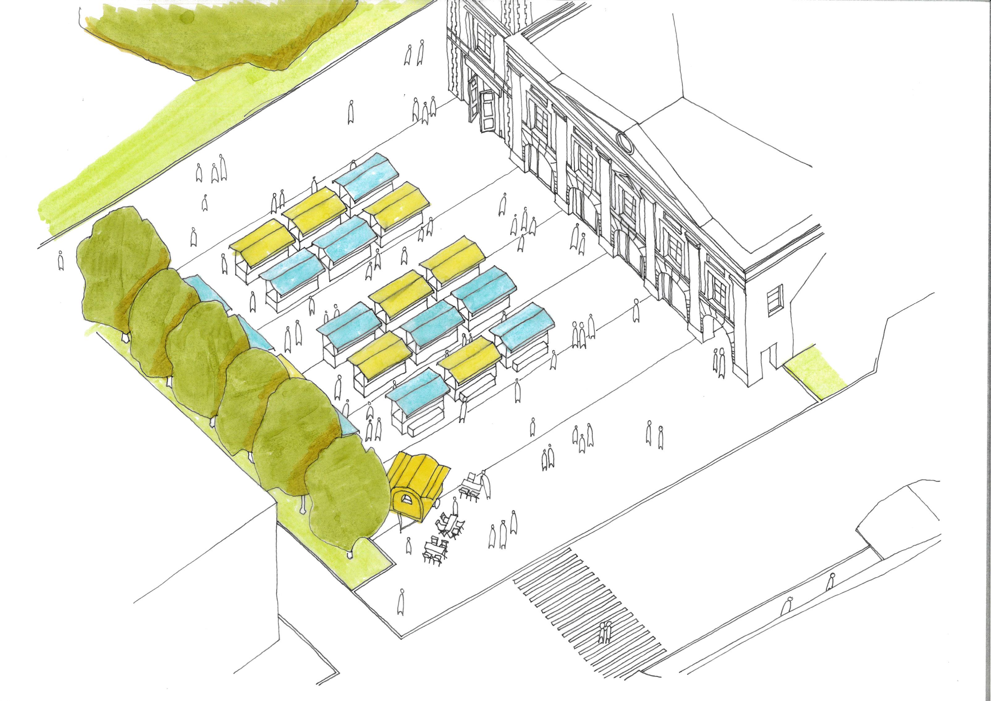
The North Square is the principal public space of the scheme, breathing new life into the old market square which was first used in the 1850’s. The space will have a diverse range of activities throughout the year, creating a varied and constantly active space which can be used throughout the year.
Key to achieving this level of flexibility is the introduction of a ‘technical deck’ below the square - an approach first noted by Pablo Sendra and Richard Sennett in their book “Designing for Disorder”. This would see a network of electricity & data cables along with water & drainage pipework installed below the square, with pop-up outlets positioned across the space at key intervals. This allows “a diversity of planned and spontaneous activities in
Recurring Weekend Market Special Events


Landscaping
Interwoven Threads
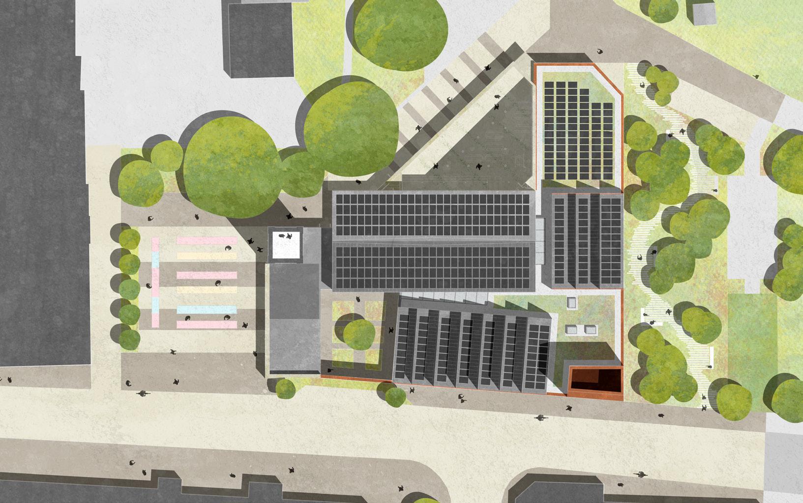
The wider landscape strategy looks at the surroundings as a number of threads, with the site acting as a nexus point to weave these individual strands together. Public realm interventions extend beyond the ‘red line’, encompassing the various streets and squares which connect the site to the wider context of Old Town.
A key tool is the use of surface materials, utilising a consistent language of two key materials which form all hard landscaping interventions in the area. These have been specified as a hard wearing Yorkstone setts - a hard wearing alternative to the local limestone, in complimentary red and cream hues to reference the ashlar stone and brick palette of the proposed building. Public realm surface finishes are ‘toothed’ into those internally and those within courtyards; the continuous language blending inside and outside spaces.


Ground Floor Plan
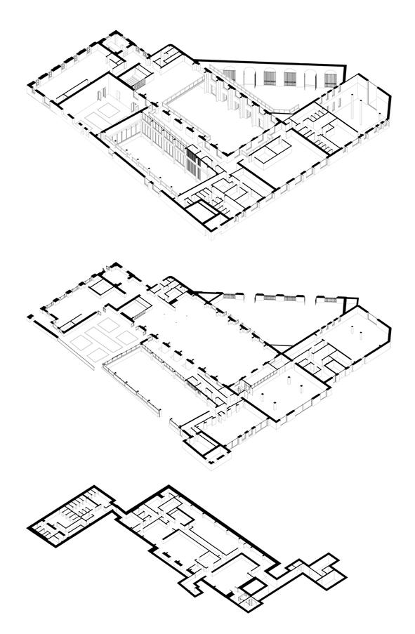
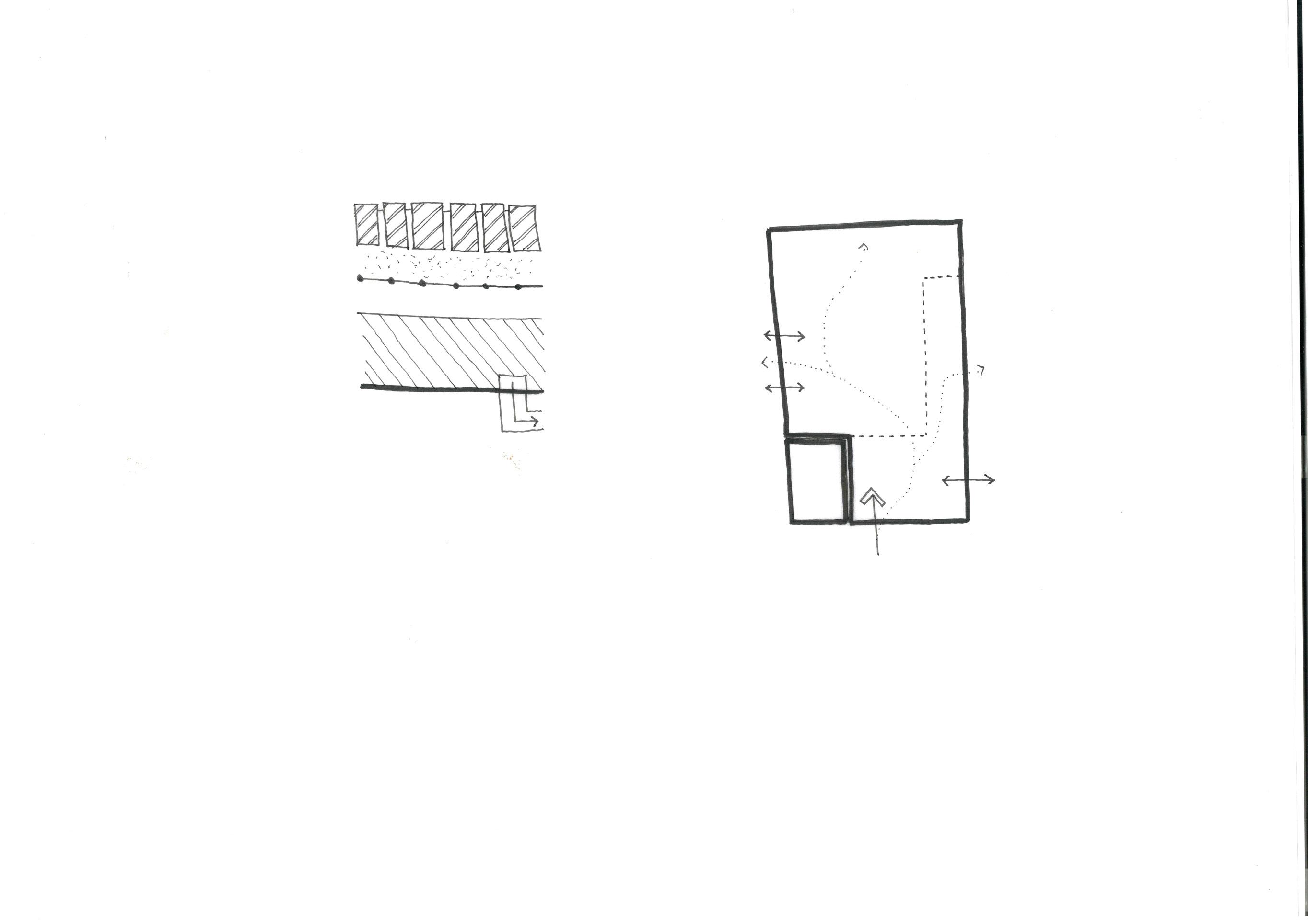
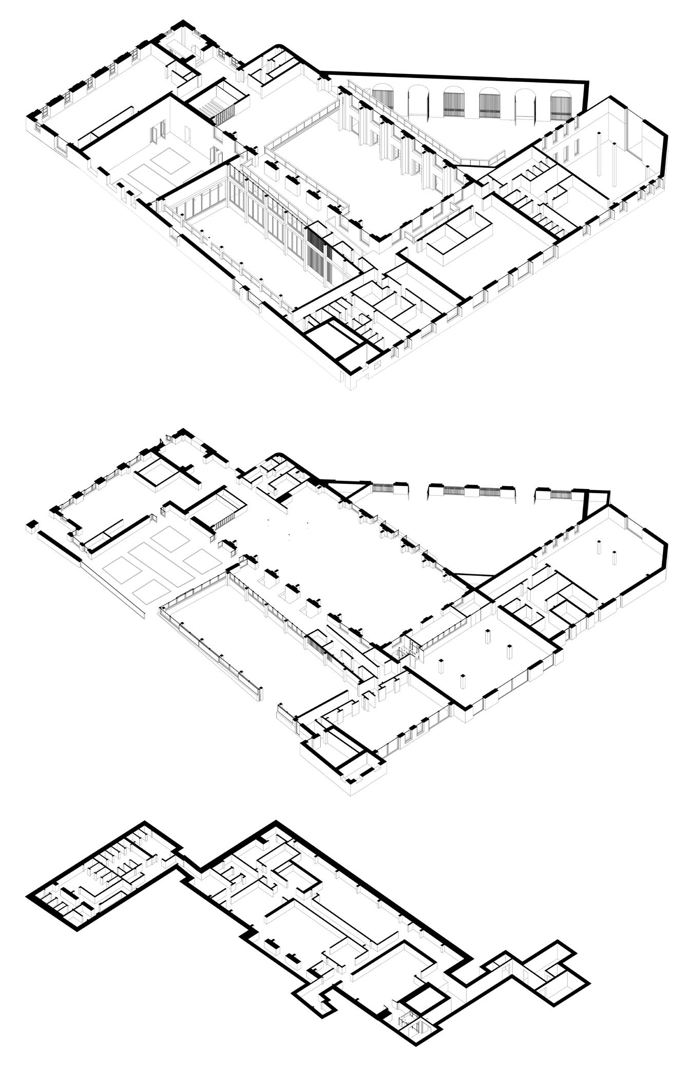
The proposal is planned around an inflection of public and manufacturing zones, reflecting the historic and new elements of the scheme. Interfaces at the boundaries provide opportunities for the public to observe and understand the roles the various spaces play in the continued operation of the building.
As explored previously, the building is a permeable entity, able to be entered and explored from several angles. This naturally draws the users into the heart of the proposal; the taproom. From here, each distinct aspect of the building are visible, and the served/ service boundaries typical to food & drinking establishments are blurred.
Packaging & Storage
Hydroponics Growing Hall Observation Space Brewing Hall
Seminar Room
Changing Places W.C
The Taproom
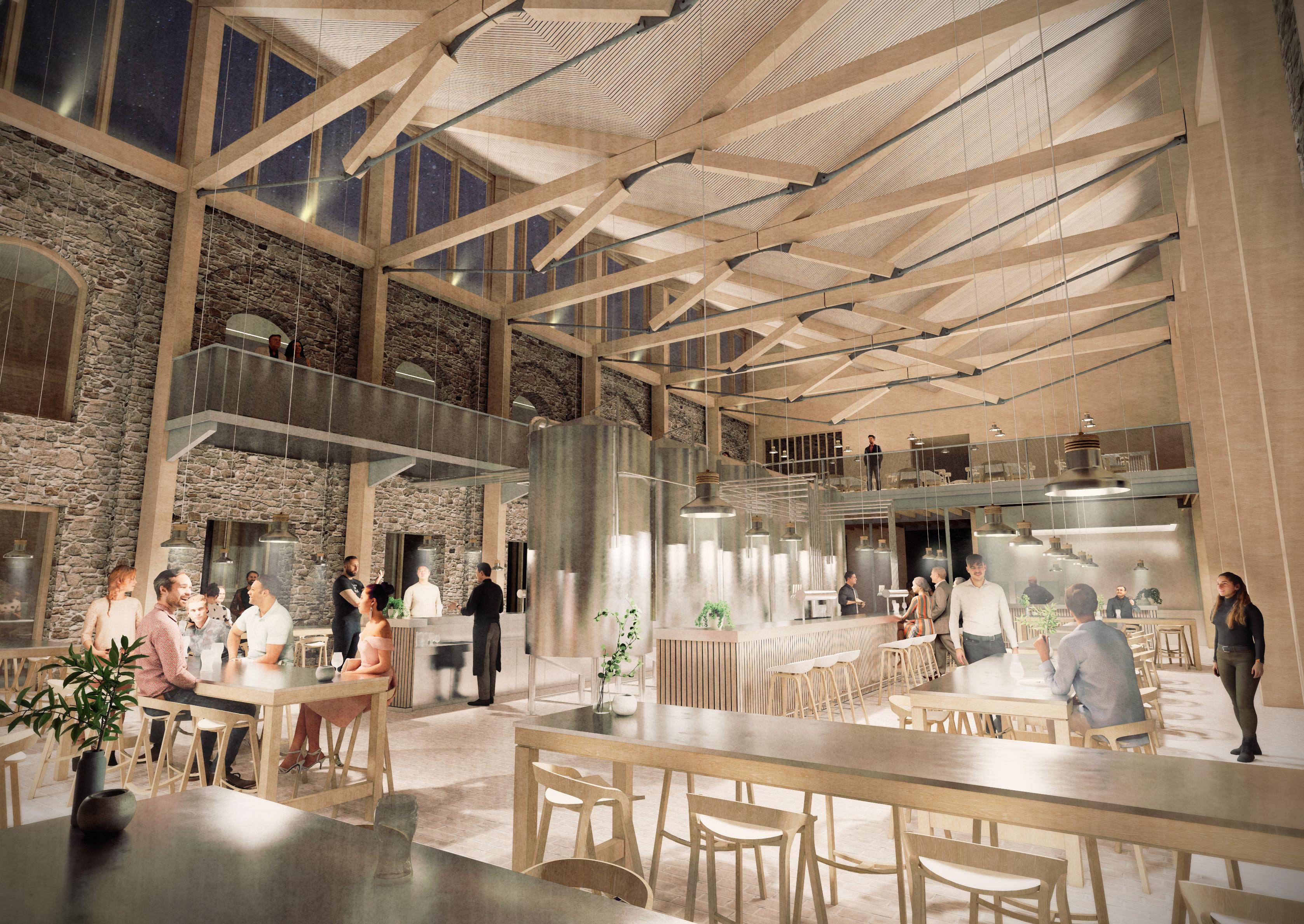
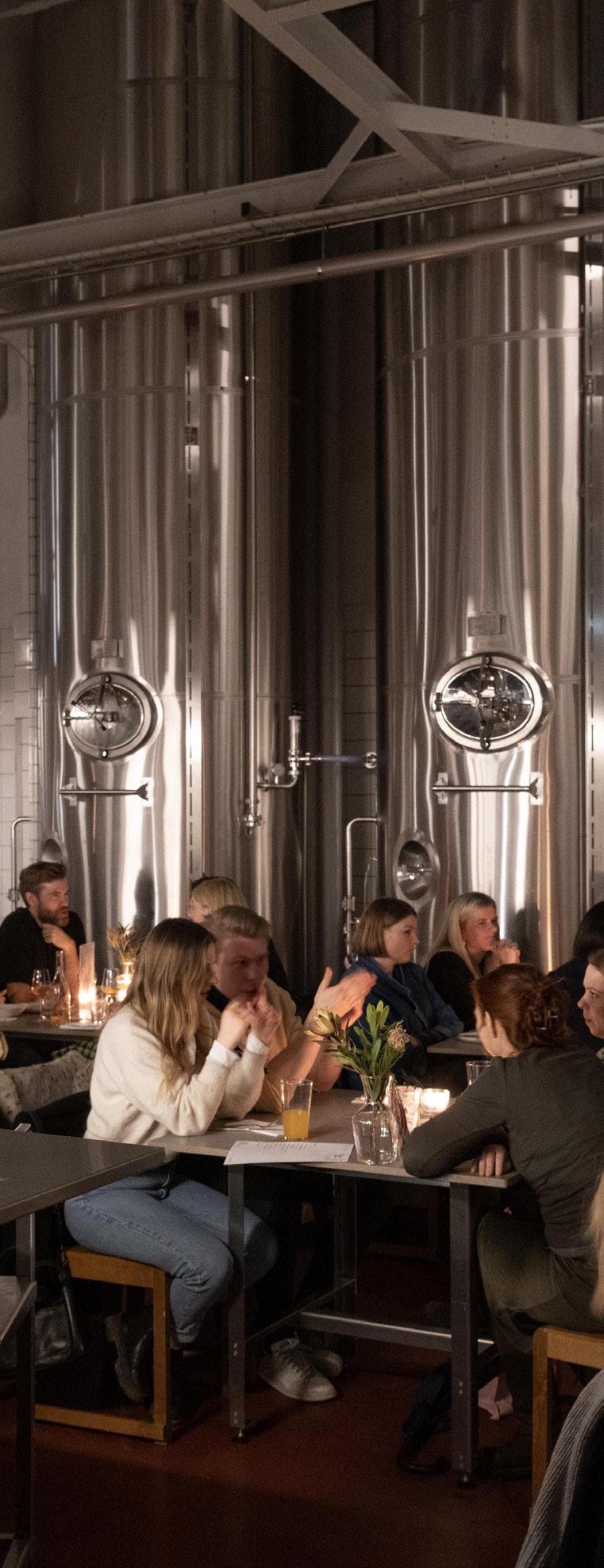
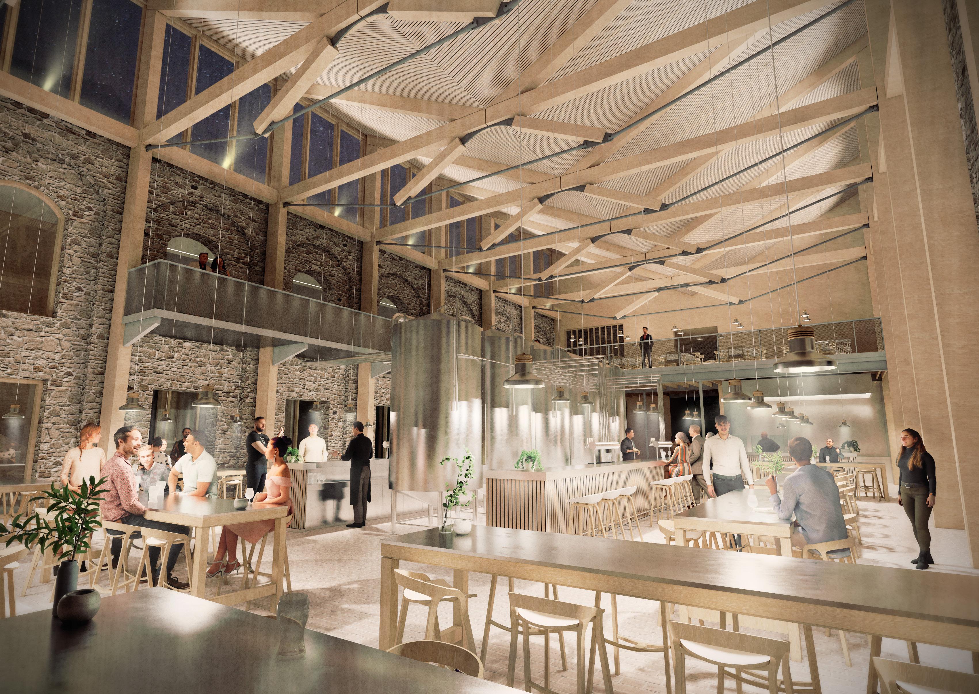
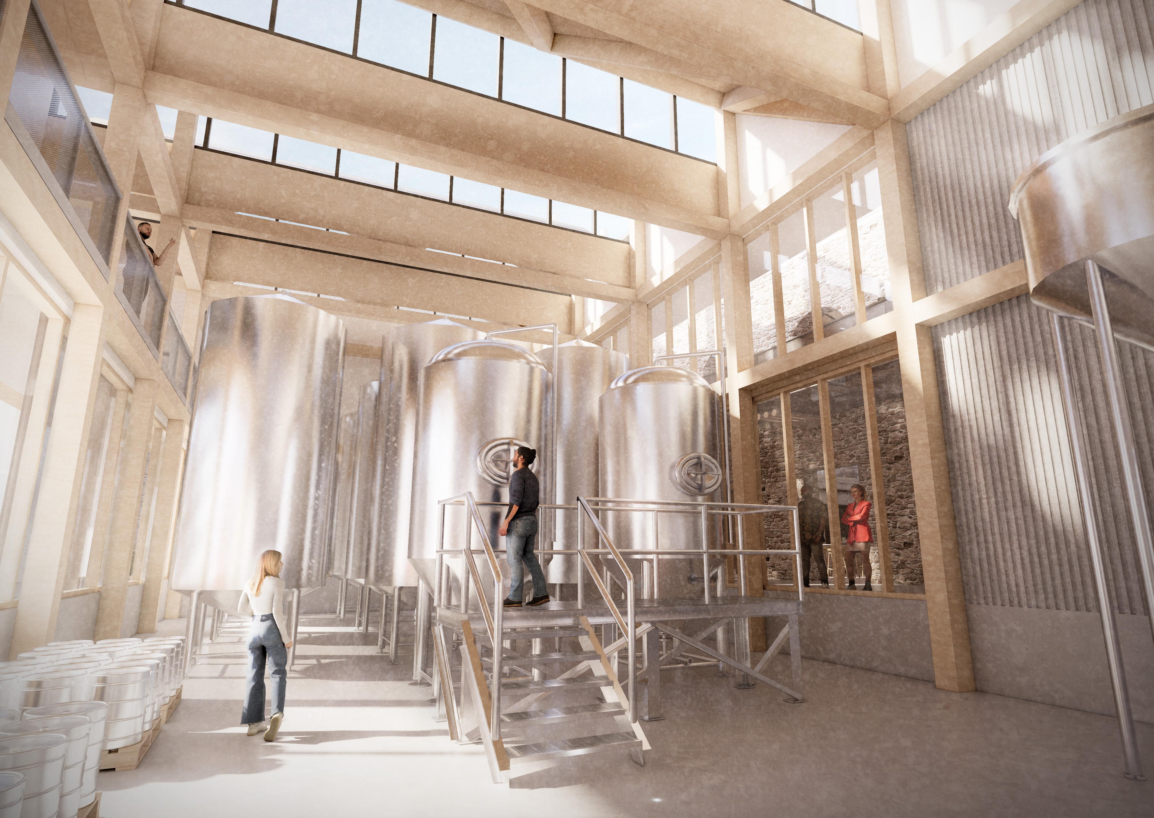
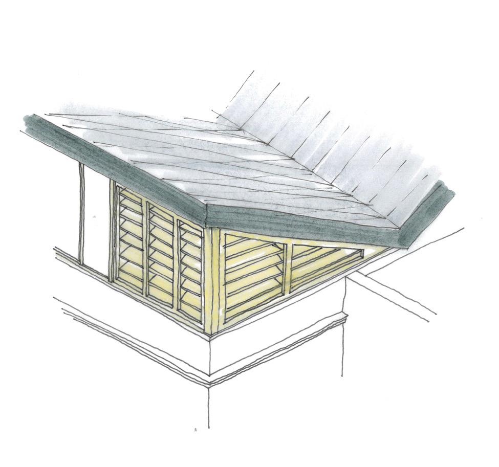
Sitting centrally in the scheme and flanked by a beer garden and the brewing hall, the taproom is a dramatic space occupying the historic Corn Exchange. Glulam trusses provide a rhythm to the hall, and supports a butterfly roof which provides natural light through generous clerestory glazing.
The taproom places the public at the heart of the brewing process, with visual links established to all key aspects of the system.
A Sequence of Compression and Expansion
The movement into and through the taproom space has been curated in a way to provide a sequence of compression and expansion, creating a dramatic experience as patrons move through the space. This sequence occurs in both the horizontal and vertical planes, resulting in a multifaceted user experience in a dynamic centrepiece space.

First Floor Plan
Whilst the manufacturing spaces occupy the Ground Floor, the First Floor is dedicated to research (containing the pretreatment labs and experimental members brewing club) and to facilitating the operational spaces below. Organised around the voids punched through the slab by the double height manufacturing zones below, the approach of this floor plate is more to do with efficiency than drama; many spaces are both visibly and physically closed off to the served public zones.
The building incorporates a number of different design tools to create a varied roofscape which directly relates to the First Floor below. Key spaces are denoted by folded sawtooth roofs, with North facing lights providing diffused illumination to the spaces beneath. Long structural glass rooflights join the new building to the existing Corn Exchange, with slender double height voids beneath to bounce light deep into the plan.

Key for Section
Observation Tower (Multiple Levels)
Taproom & Bar
Restaurant
Kitchen
Corridor
Storeroom
Observation Space
Bio-hydrogen Generation & Pretreatment
Stability Chambers
Pretreatment Labs
Key for Section
Hydroponics Growing Hall
Stair Core
Plant Room
Pretreatment Labs
Bio-hydrogen Generation & Pretreatment
Corridor
Staff Break Room
Staff Offices
Staff Toilets
Seminar Room
A Patchwork of Materials
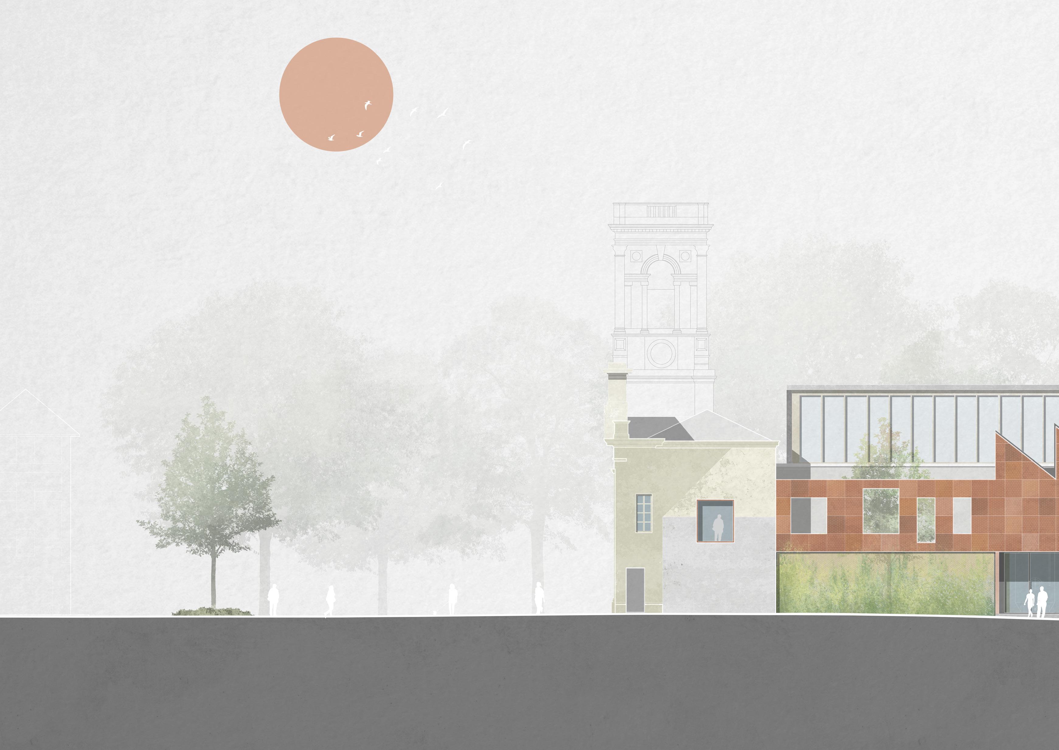
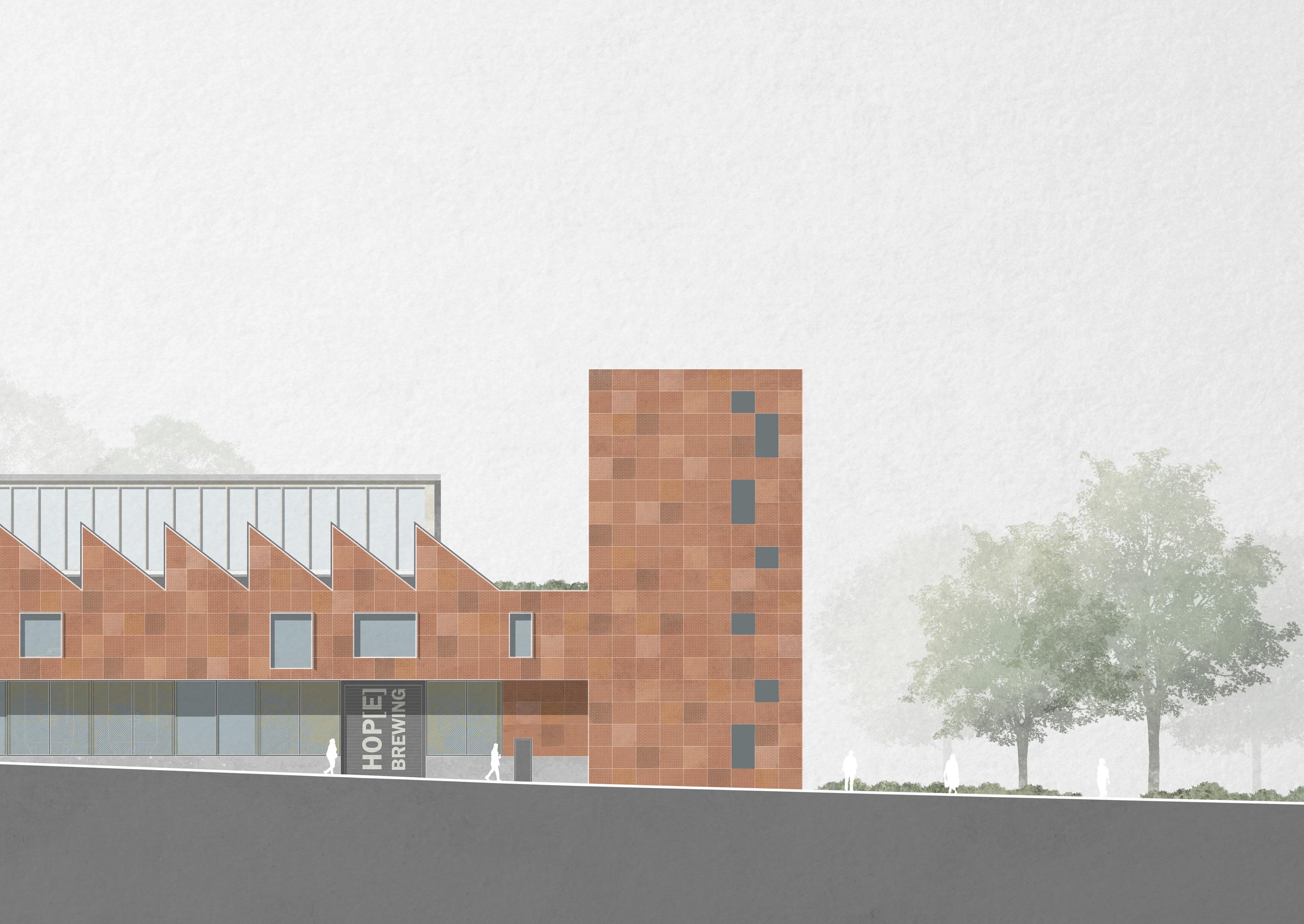
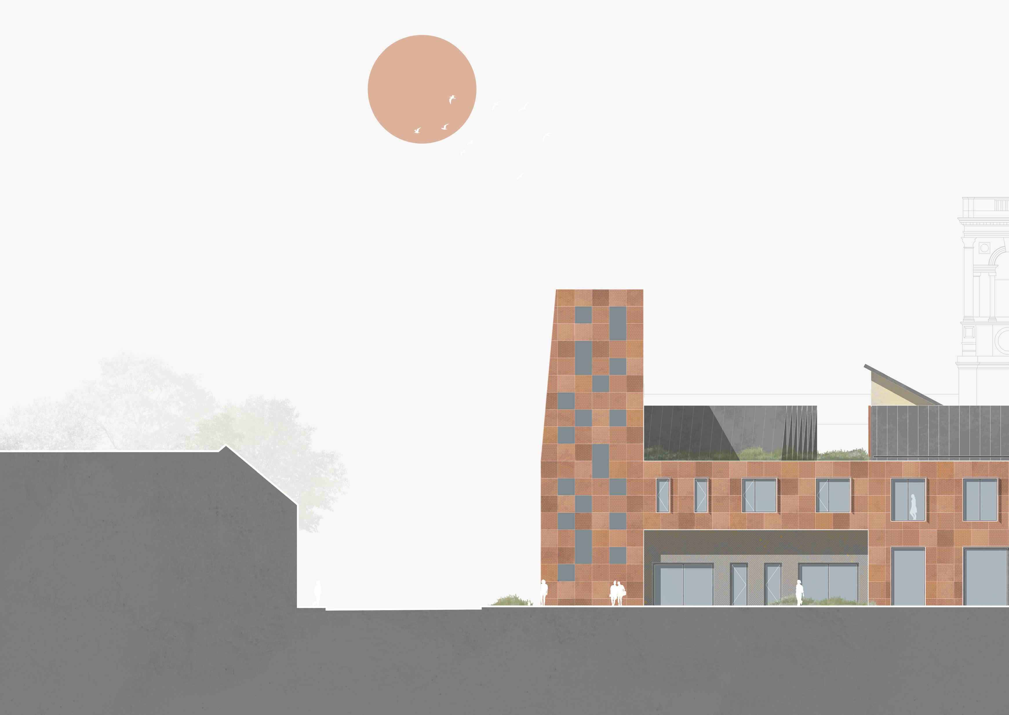
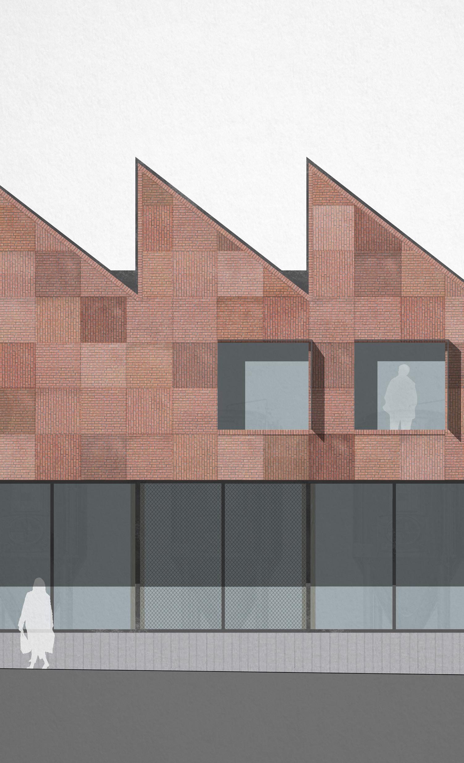
The patchwork of brick panels which characterises the new elevations can be seen as an extension of the existing West Elevation of the Old Town Hall. Years of adaptations and adjustments have left a mix of materials on this elevation; referencing the ghosts of old buildings previously demolished. Smooth ashlar gives way to painted render, which in turn gives way to rough hewn stone rubble.
This patchwork language is continued over onto the new elevations - the jump in materiality bridged by a new picture window in the upper floor of the Old Town Hall, edged in brick. The window proportions (more square than rectangular) further reference the punched openings to the new building. This slowly blurs the distinction between the existing and new elements, stitching the two elevations together into a cohesive whole.

Deliveries and Goods Circulation
The final layout consideration comes in the form of the operation of the building, and how to efficiently service each distinct zone which in turn has its own requirements for deliveries, storage and access. And as a building designed around a few manufacturing processes, the success in its operation determines the success of the building as a whole.
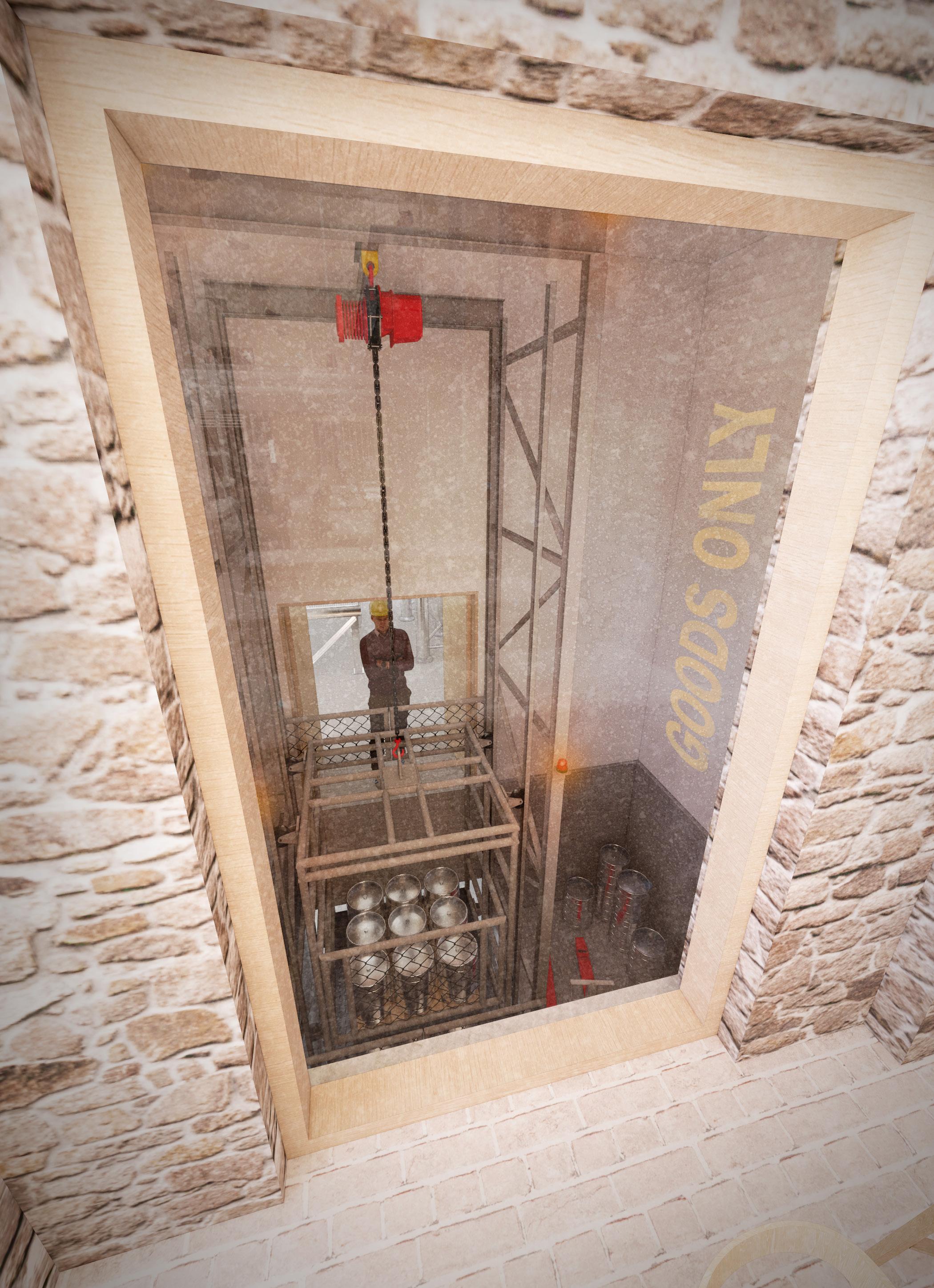
The existing basement becomes a useful tool for optimising the servicing aspects of the building. It is seen as the operational hub, the metaphorical palm of a hand with delivery ‘fingers’ poking through the ground to link key zones. A small extent of basement has been constructed to the South, extending beneath the new build elements of the scheme and providing deliveries access to the building from the South.
In line with the overarching concept of placing the public at the heart of the process, the operational aspects are put on display with one key goods lift exposed to the taproom. This creates a

Primary deliveries parking to the South East, away from the main road. Turning head provides suitable area for a fixed wheelbase lorry to turn.
Secondary deliveries parking via a pull in bay on the main road, which provides deliveries access to the brewing hall via a roller shutter door on the West elevation.
STRUCTURE & TECTONICS
Integrated Tectonic Principles
Respecting the Historic Fabric
All new interventions in and around the Listed Town Hall and Corn Exchange respect the existing fabric; designed sympathetically and with disassembly in mind.
A Clear Distinction between New and Old
The use of light and heavy materiality are used to create a dialogue between new, old and reused, ensuring the various parts of the building are easily legible.
A Language of Reuse
Material reuse has been prioritised wherever possible, and used as a driver for decision making. New materials are low carbon in their specification.
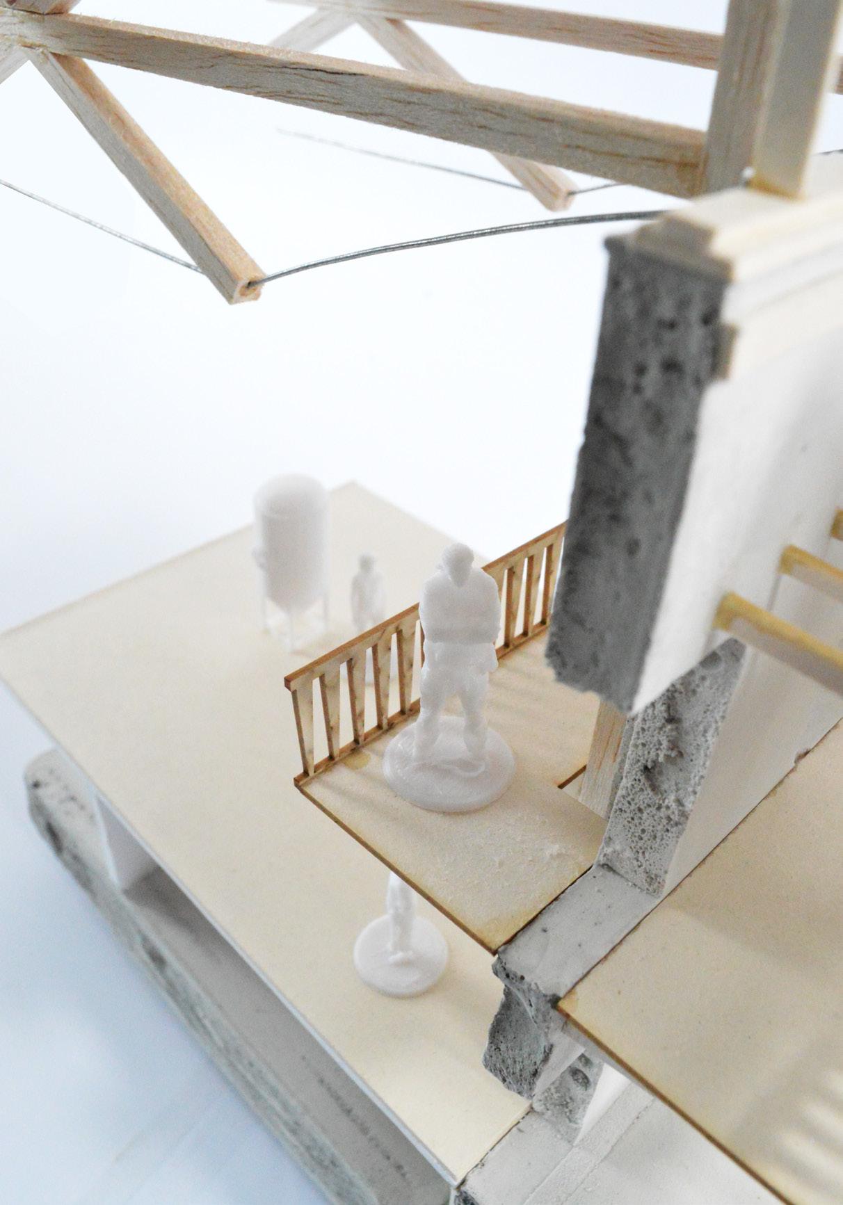
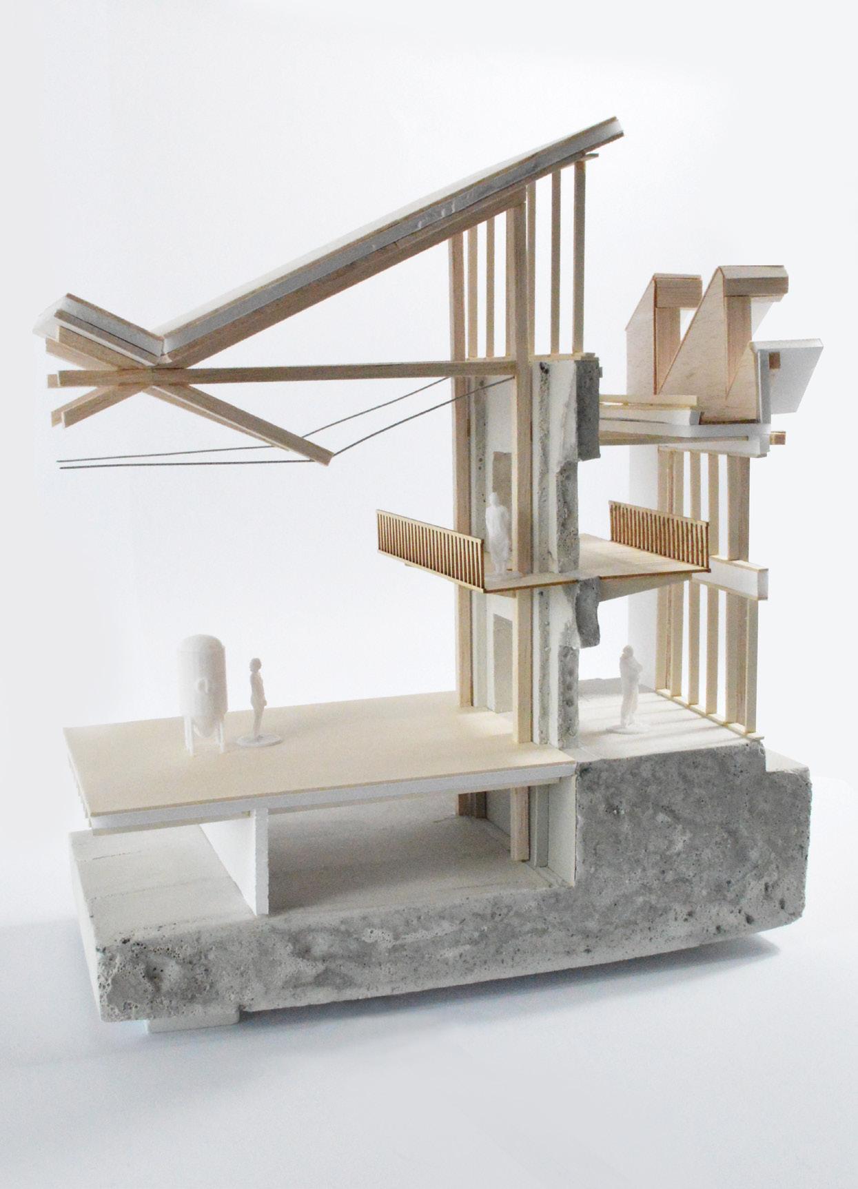
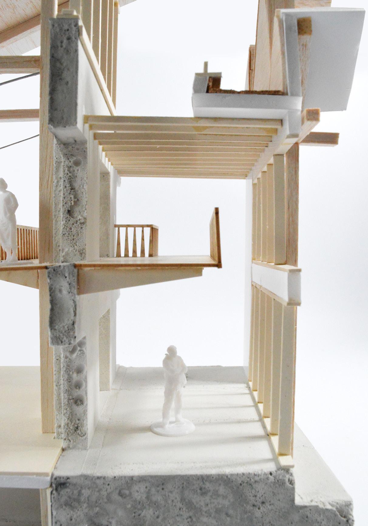
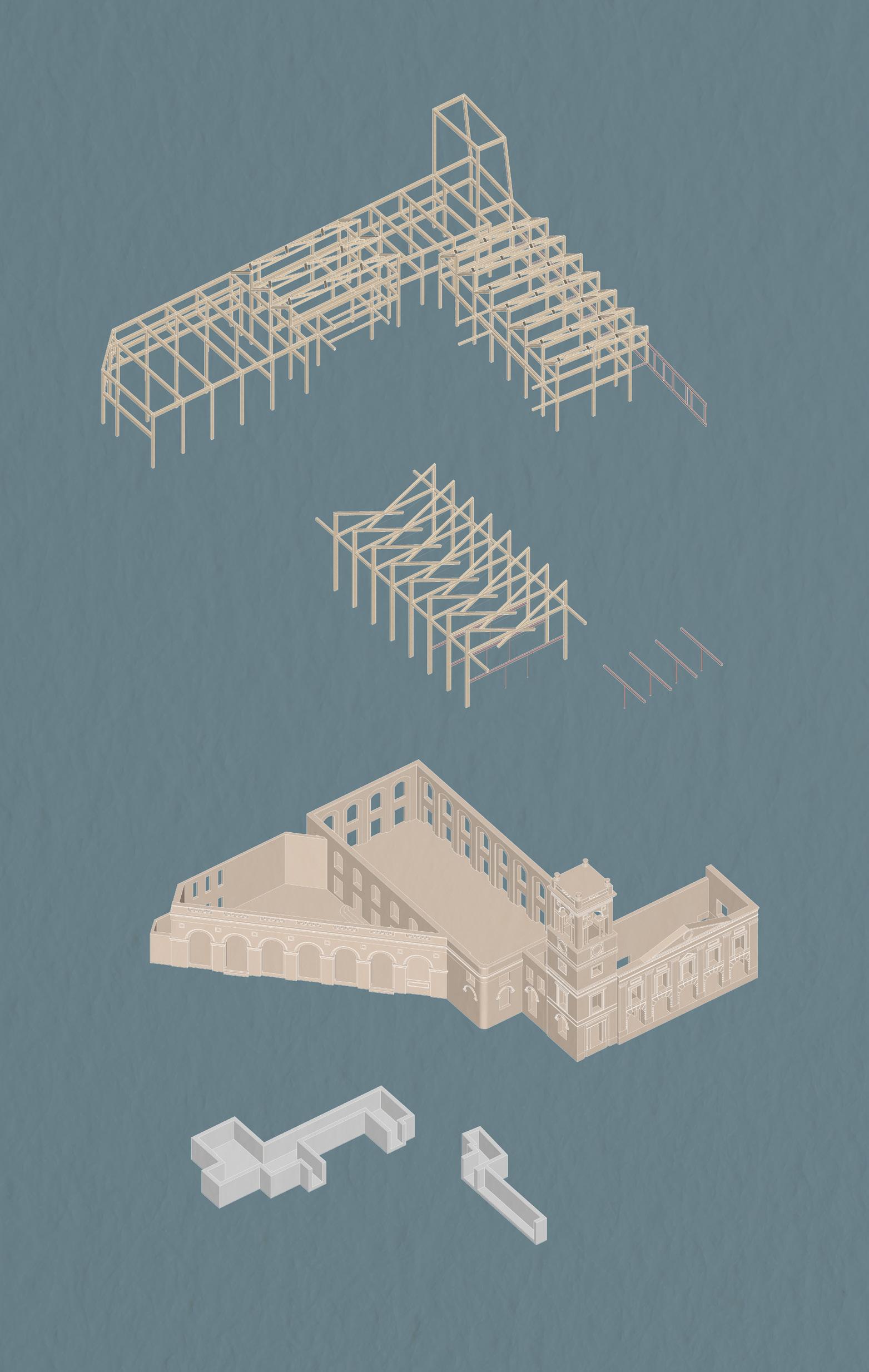
Scales of Intervention
1. Glulam Primary Structure
300 x 300 glulam columns to brewing hall, 400 x 400 glulam columns elsewhere.
400 x 600 glulam beams to green roofs, 300 x 300 glulam beams to sawtooth trusses.
225 thk glulam shear walls (refer to plans on following page for locations).
2. Glulam Butterfly Trusses and Steel Structure
250 x 500 glulam columns with 250 x 350 beams forming trusses; tied with 24 dia. s/s cable.
305x165x46 UB steel beams forming mezzanine supported on 100 dia CHS columns.
Existing cast iron columns inspected following fire damage and repaired/replaced as necessary.
3. The Existing Building
All existing walls will be inspected for structural integrity (due to previous fire damage) with stability improvements made as required.
New door openings etc. to be supported with steel lintels to suit spans.
4. New Basement
150mm thick concrete retaining walls and floor slab to new basement, with concrete utilising unhydrated cement and aggregate demolition waste extracted from existing concrete frame (utilising proprietary Freement “Smart Liberation” technology).
Structural Grids
The proposal utilises a mixture of offsite technologies and site cut elements to maximise ease of construction. Whilst the glulam primary frame can be manufactured off site to minimise waste, the timber joists spanning between the new frame and existing building will be cut to size on site; a simple solution to span the varying distances.
Differentiating New and Old
The scheme proposes a clear tectonic strategy to clearly differentiate historic, reclaimed and proposed elements. New structure is typically lightweight timber, contrasting with the heavier masonry of the existing building. This creates a strong narrative of levels of permanence - the new lightweight structure easily removable at the end of its life, whereas heavier elements (including those reclaimed) are tied to the site either in their historic form or reimagined for a new lease of life.
Materiality
The materiality of the scheme focusses on reuse where possible, and so the selection and quantity of materials present following the demolition of the existing building has guided and informed these decisions.
The proposal endeavours not to purely reuse materials in their original forms, but to reimagine how they may be reused or repurposed into forms not originally intended. This both extends the life of materials which would otherwise be waste, and opens a crucial dialogue on how new projects elsewhere in Swindon, the UK or across the world can reuse these old materials.
Reusing materials in this way also places them in a position where they could be further reused at the end of this proposal’s design life. The grid of brick panels, freed of the constraints of their cement mortar, can be easily disassembled and reused as wall panels elsewhere, turned into floor finishes or used as landscape interventions. Slicing the remaining precast planks to form new cladding panels opens a discussion about the future of the still intact planks (reused as flooring) - offering multiple options for their continued reuse beyond rubble and aggregate.
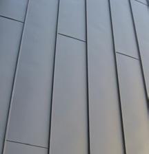
Reuse of the existing zinc standing seam panels provides a lightweight & cost effective roof finish perfect for mounting PV arrays.
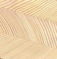
Large quantities of British larch are available due to the spread of the fungus phytophthora ramorum[26] , making larch a more sustainable timber specification than other species at present.
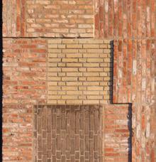
The direct reuse of the existing brickwork provides a tangible visual link to the previously existing building.
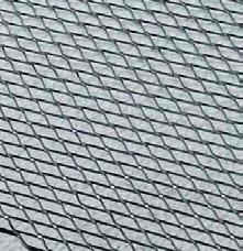
An industrial material which compliments the reused brickwork panels, introduced on the ground floor levels to provide a level of privacy to the spaces within.
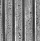
An experimental reuse of the remaining precast planks not used for flooring elements. These will be sliced vertically to expose the ribs; introducing a subtle rhythm and textured quality to the facade.
Resource Flows
Reclaimed from Demolition Use in Proposal


The reuse of the existing concrete frame is reliant on the use of an emerging technology known as concrete atomisation, developed by the Dutch company Rutte Group under the trade name ‘Freement’. This technology used a special machine to atomise the concrete, shaking it at an extremely high frequency to the point the molecules of individual materials seperate into their component forms (i.e. cement, sand and aggregate). This process ‘liberates’ the unhydrated cement - of which there is typically ~50% - which can then be rehydrated in new concrete products[27]
Construction Sequence
Is is assumed that the existing Town Hall & Corn Exchange will be cleared of all vegetation, waste etc. during the pre-construction phase to enable detailed surveys to take place, so these works are not included in the sequence below.
1. Site Establishment
Hoarding erected to site perimeter, site compound established in the Southern car park. Protection installed to existing Listed building and to adjacent mature trees.
2. Demolition
‘The Forum’ carefully demolished and materials retained in site compound for later use. Brick panels are cut out and stored at this stage. Alteration works to Listed building are also undertaken with suitable temporary propping installed as required.
3. Groundworks
Oversite reduced to required levels, new piled foundations bored and cast along with new extents of basements. Existing walls are underpinned as required. Substructure works completed and ground floor slabs cast.
4. Primary Structure
Primary glulam and steel structure is craned in and installed. Retained concrete floor panels craned in to form floor decks and new CLT roof panels installed.
5. External Envelope
Prefabricated timber frame cassettes installed between primary structure to form external walls. Glazing installed prior to insulation and external finishes. Salvaged brickwork panels are cast onto their backing panels during previous construction stages to optimise programme. Retrofitting works carried out to existing building. The building will be watertight at the end of this stage.
6. Servicing
Plant equipment, ventilation ductwork and first fix installed across the site. Continuous airtightness layer established at the end of this stage.
7. Internal Finishes and Landscaping
Internal finishes and second fix installed throughout, with brewing equipment delivered and fitted. In tandem, landscaping, green roofs and the Solar PV array will be installed. Site compound will be demobilised and the building handed over to the client.
Embodied Carbon
With the prioritised use of retained and salvaged materials, the use of industry standard embodied carbon calculation tools do not give an accurate representation of the overall quantities present in the scheme. Therefore, estimates of embodied carbon have been calculated manually, with average rates added for other materials not included below. Carbon sequestering materials have been specified where possible. The calculations show the building falls well within the LETI 2030 embodied carbon targets. This implies the building would still be within these targets if subjected to a more stringent whole building embodied carbon calculation, due to the extent by which it exceeds the standards[28][29][30]
Whole Building Embodied Carbon
Excluding (Left) and Including (Right) Sequestration
Larch Glulam
Embodied carbon: 0.28 kgC02e/kg
Carbon sequestration -1.36 kgC02e/kg
Net biogenic embodied carbon: -1.08 kgC02e/kg
Quantity required: 226.6m3
Larch CLT
Embodied carbon: 0.25 kgC02e/kg
Carbon sequestration -1.36 kgC02e/kg
Net biogenic embodied carbon: -1.11 kgC02e/kg
Quantity required: 160m3
Low Carbon Offsite Mixed Concrete
Embodied carbon: 0.132 kgC02e/kg
Quantity required: 490.9m3 (674.9m3 - 184m3 reclaimed)
Steel (Connections & Trusses)
Embodied carbon: 1.37 kgC02e/kg
Quantity required: 1.59m3
Hemp Insulation
Embodied carbon: 0.10 kgC02e/kg
Carbon sequestration -1.36 kgC02e/kg
Net biogenic embodied carbon: -1.26kgC02e/kg[31]
Quantity required: 1721.7m3

Sourcing of Key Offsite Materials
Transport by train: 0.04 gCO2e/kg/mile (prioritised where possible).
Transport by road: 0.17 gCO2e/kg/mile.
Glulam & CLT
A1-A3 embodied carbon:
+31,640 kgC02e -122,040 kgC02e inc. sequestration
A1-A3 embodied carbon:
+20,000 kgC02e
-88,800 kgC02e inc. sequestration
Source: Buckland Timber (Devon, EX17
Distance: 120 miles
Transport carbon (A4) per journey by train: 926.4 kgC02e
Transport carbon (A4) per journey by truck: 3,937.2 kgC02e
Source: CELSA Steel (Cardiff, CB4 0GA)
Distance: 71 miles
Transport carbon (A4) per journey by train: 35.2 kgC02e
Transport carbon (A4) per journey by truck: 149.7 kgC02e
A1-A3 embodied carbon:
+155,517 kgC02e
A1-A3 embodied carbon:
+16,990 kgC02e
A1-A3 embodied carbon:
+19,800 kgC02e
-249,473 kgC02e inc. sequestration
Source: Heidelberg Materials (Swindon, SN2 8DW)
Distance: 5 miles
Transport carbon (A4) per journey by train: N/A
Transport carbon (A4) per journey by truck: 1,001.4 kgC02e
Carbon Offsite Mixed Concrete Totals (A1-A4) Excluding Sequestration
Insulation
Source: Hemspan (Cambridge, CB4 0GA)
Distance: 114 miles
Transport carbon (A4) per journey by train: 902.9 kgC02e
Transport carbon (A4) per journey by truck: 3,837.1 kgC02e
(A1-A4) Including Sequestration
A 20% flat rate has been added to the calculated embodied carbon to allow for elements not included above, including timber frame panels, internal fitout, MEP etc, calculated from the non-sequestered embodied carbon value.
A - Pitched Roof Buildup
U Value: 0.11 W/m2K
Reclaimed zinc standing seam roofing
Proprietary breather membrane, all joints taped and sealed
18mm WBP plywood carrier board
38x50mm s/w battens forming ventilated void
300mm hemp insulation batts (0.038 W/mK) fixed with low conductivity fixings
Proprietary vapour control layer, all joints taped and sealed
100mm larch CLT slab (using VOC & formaldehyde free adhesives) fixed back to structure
Larch glulam structure (see specification prior)
Bespoke acoustic insulation panels between structure (see pg. 92 for details)
C - Basement Floor Buildup
U Value: 0.15 W/m2K
Clear epoxy coating over screed (increased durability for goods moving equipment and high levels of foot traffic)
50mm liquid screed with 14mm UFH pipework beneath
Recycled polythene separation layer
150mm high compressive strength hemp insulation
Radon DPM (specified in accordance with BR211) with all joints taped and sealed)
150mm reinforced concrete slab, utilising unhydrated cement and recycled aggregates from earlier demolition works
150mm compacted sulphate-free hardcore formed from crushed demolition waste
B - Flat Roof Buildup
U Value: 0.16 W/m2K
Recycled FPO fully adhered dark grey single ply membrane (with proprietary drainage layer, membranes and growing substrate over where green roof, with planting as pg. 96)
200mm hemp insulation boards (0.038 W/mK) with integrated glass fibre tissue upper face (allowing for installation of adhered membrane)
Fully adhered elastomeric VCL to single ply manufacturers specification, with all joints taped and sealed
18mm WBP plywood
Timber firings (min. 25mm depth) cut to falls of 1:80
200x50mm C24 larch joists at 450mm c/c, PAR/PSE
12.5mm plasterboard with skim & paint finishes between joists, fixed back to 38x50mm s/w battens
D - Intermediate Floor Buildup
U Value: N/A
50mm brick floor finish (existing reclaimed panels halved to form ‘thick slips’)
50mm liquid screed with 14mm UFH pipework beneath
Recycled polythene separation layer
50mm high compressive strength hemp insulation preventing downward heat movement from UFH
22mm t&g chipboard flooring glued and screwed to joists below
200x50mm C24 s/w joists at 450mm c/c
100mm acoustic insulation batts between joists
2no. layers 15mm plasterboard with all joints staggered and skim and paint finishes over, providing 60 minutes fire resisting construction
E - Brick Panel External Wall Buildup
U Value: 0.14 W/m2K
1x1m 102.5mm reclaimed brick panels cast onto 25mm concrete backing panel (utilising unhydrated cement and recycled aggregates from earlier demolition works)
Panels tied back to timber frame inner leaf with thermally broken basalt wall ties with insulation retention clips
150mm hemp insulation batts fully filling cavity
Proprietary breather membrane over plywood, all joints taped and sealed
18mm WBP plywood sheathing board
140x50mm s/w timber frame
100mm hemp insulation batts between studs
Proprietary vapour control layer, all joints taped and sealed
38x50mm s/w battens forming service void
12.5mm plasterboard with skim & paint finishes
G - Concrete Dwarf Wall Buildup
U Value: 0.15 W/m2K
75mm thick ‘halved’ recycled concrete planks (from existing demolished building) as outer cladding, cast onto 50mm concrete panel (utilising unhydrated cement and recycled aggregates from earlier demolition works)
150mm thermally broken galvanised steel fixing clips
150mm XPS insulation suitable for use below DPC; utilising ultra low GWP blowing agents
Radon DPM (specified in accordance with BR211) with all joints taped and sealed)
150mm reinforced concrete kerb (utilising unhydrated cement and recycled aggregates from earlier demolition works)
F - Cantilevered Soffit Buildup
U Value: 0.16 W/m2K
50mm liquid screed
25mm hemp insulation batts
Proprietary vapour control layer, all joints taped and sealed
150mm precast concrete planks, reused from existing demolished building and supported on steel angles fixed back to primary structure
Proprietary breather membrane, all joints taped and sealed
200mm thermally broken soffit brackets
150mm hemp insulation batts fixed between brackets with proprietary screws/plugs 18mm WBP plywood
Black coloured breather membrane over plywood, all joints taped and sealed
Galvanised EML mesh to soffit fixed over plywood
H - Ground Floor Buildup
U Value: 0.15 W/m2K
200mm reinforced concrete slab (suitable for vehicle and fermentation tank loadings) cast to falls towards central drain
Radon DPM (specified in accordance with BR211) with all joints taped and sealed)
150mm XPS insulation suitable for use below DPC; utilising ultra low GWP blowing agents
150mm compacted sulphate-free hardcore formed from crushed demolition waste

The Butterfly Truss
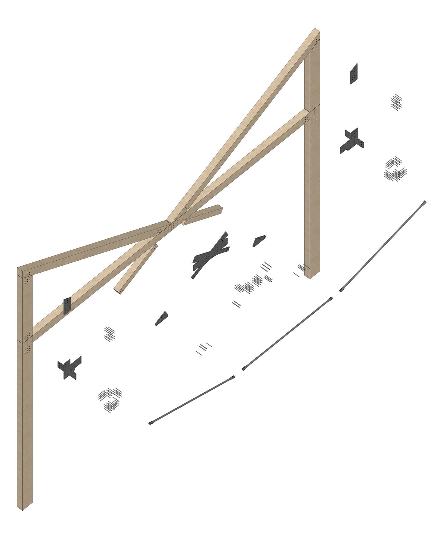
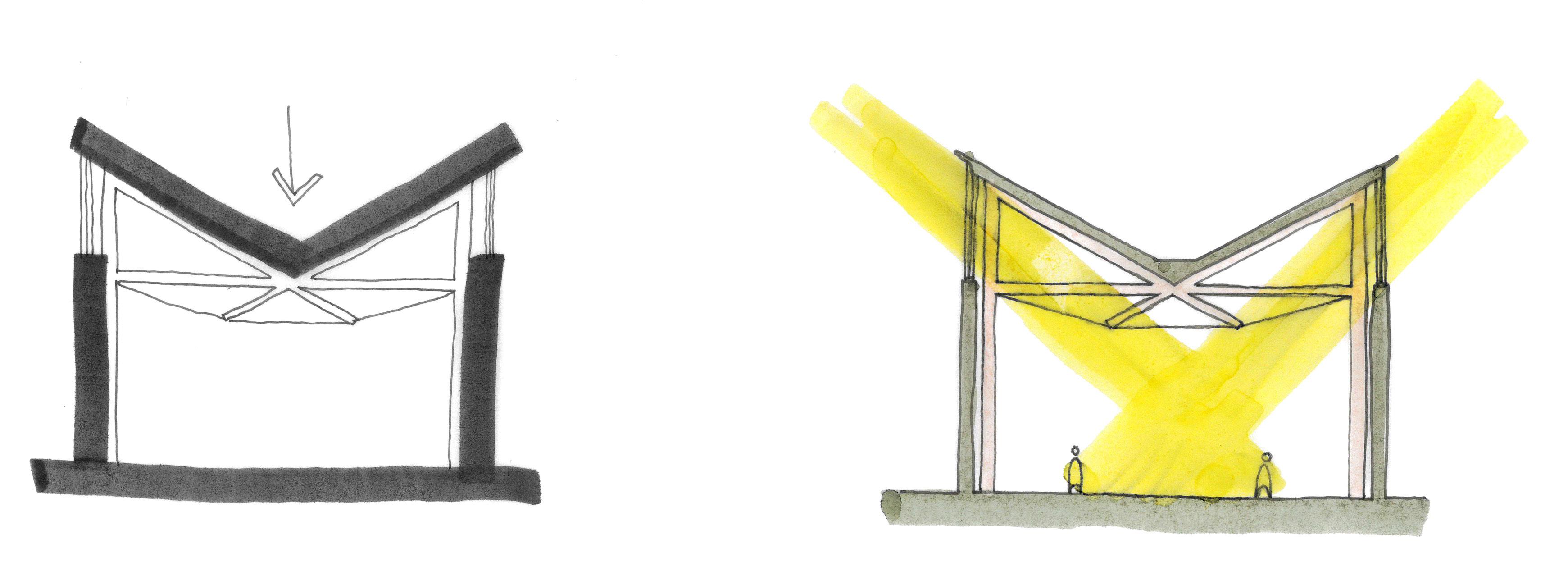
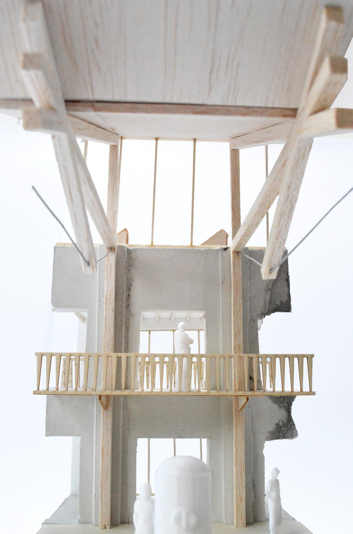
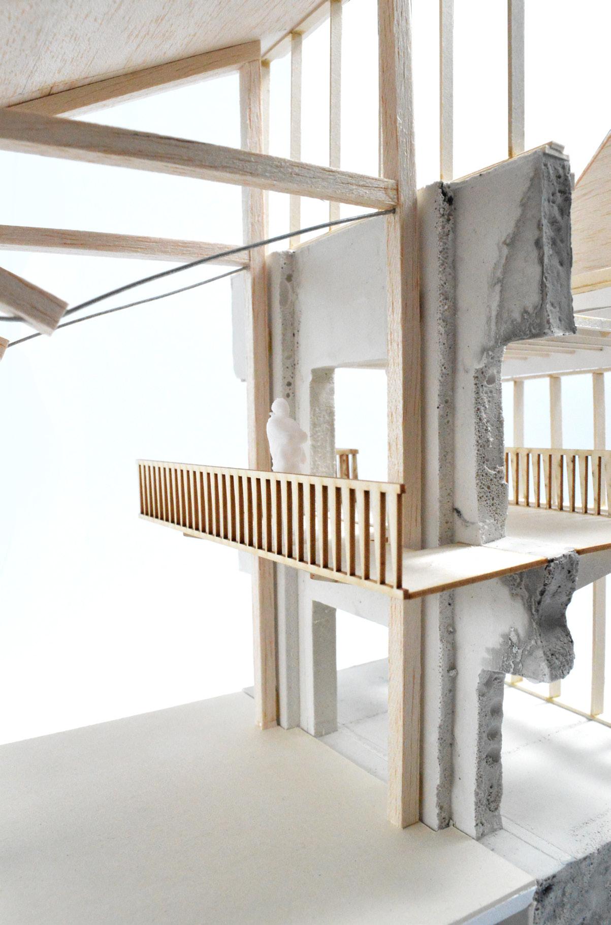
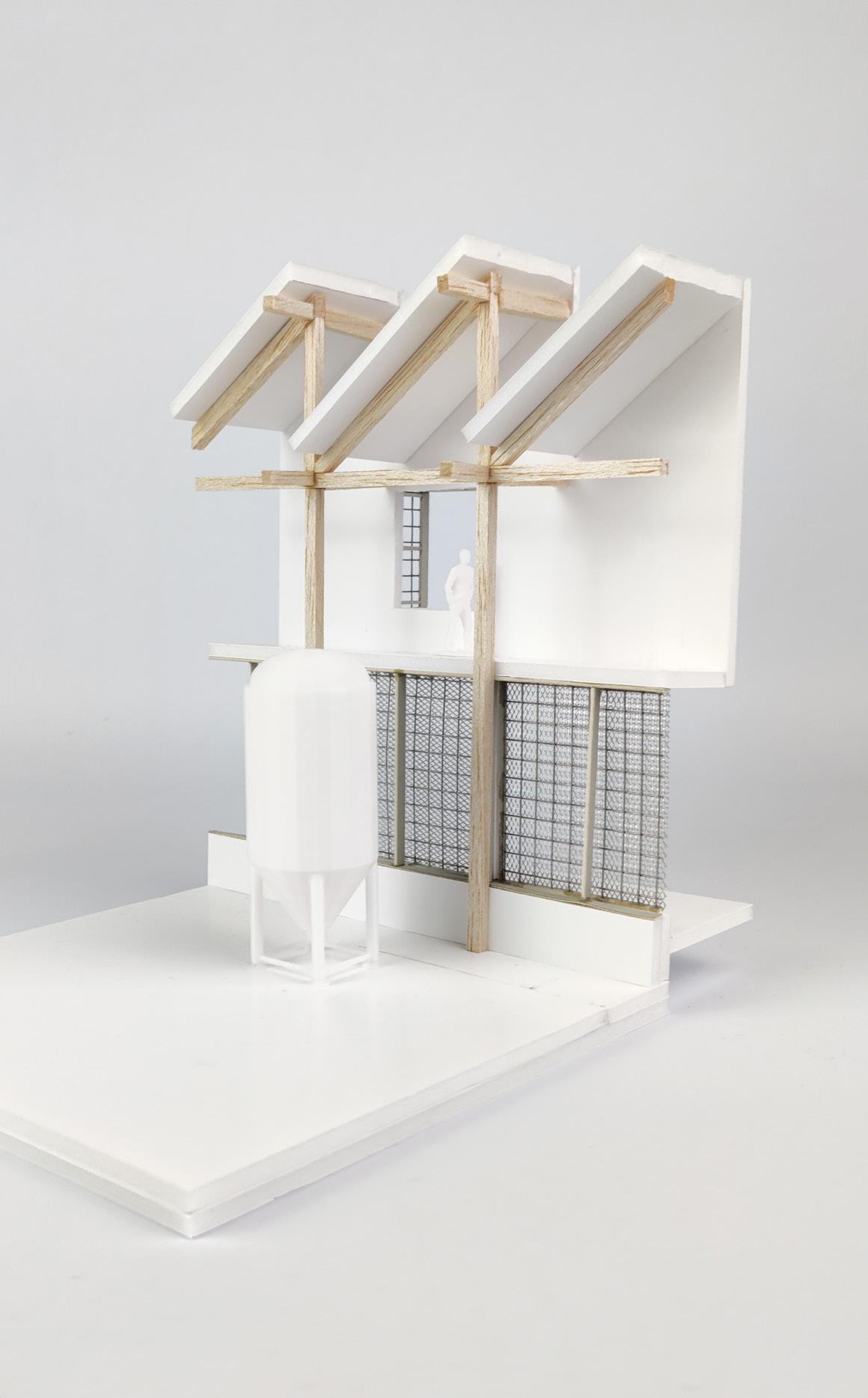
The structural intervention in the taproom hall takes the form of a glulam butterfly truss, a lightweight structure which supports the roof above whilst allowing for generous clerestory above the existing walls. These elements come together to create a language of insertion, with the existing stone walls acting as a container for the new structure.
The truss is comprised of four key elements, as follows:
1. 350x500mm larch glulam columns, fixed back to existing wall with s/s brackets
2. 350x250mm larch glulam beams
3. 200x200mm larch glulam beams connecting centroid plate to cables
4. 24mm diameter stainless steel cables
The primary benefit of a truss of this type is that all forces are contained within the members, with no external forces applied on the existing building apart from at the base of the columns. In turn, this ensures there will be no long term damage to the existing walls; the frame can hypothetically be removed at the end of the building’s life and leave no imprint on the existing structure.
Typical Connection Assembly Sequence
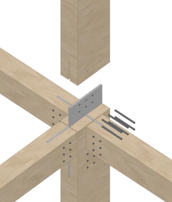
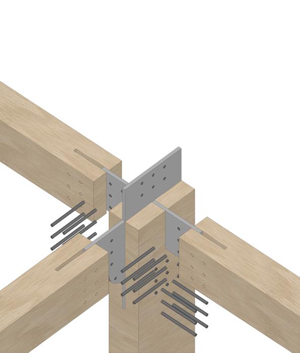
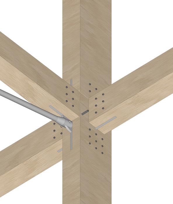
Exploded Truss Assembly
Stage 1
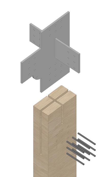
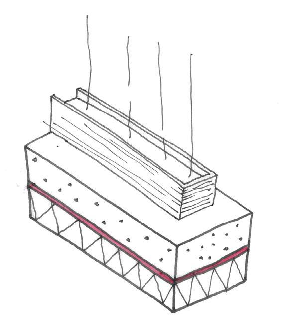
A steel flitch plate is inserted into a series of routed grooves in the glulam column (completed offsite for accuracy), and bolted with M14 bolts.
Stage 3
The upper section of the column is craned into position and bolted.
Stage 2
Horizontal beams are craned into position and bolted sequentially - the centre member of the truss supported until other members are fixed.
Stage 4
The steel cable eyelet / bracket is bolted to the flitch plate, with the cable fixed and tightened to spec once all truss members are fixed.
The Roof
Formed from a CLT roof deck sat on the inserted glulam trusses, the roof sits lightly over the existing walls and reads as a canopy. Reusing the salvaged standing seam panels and insulated with low carbon hemp insulation batts, the roof has minimal visual and environmental impact.
The glazing and roof edge details have been developed to minimise profiles and exposed frames - pushing the language of a canopy through to the detail. The upper glazing transom is restrained by a concealed steel angle, hiding the frame behind the underside of the roof - from inside, only the mullions are visible. Tapering upwards, the roof construction finishes in a thin zinc lip - removing the chunky, heavy
BReturn ‘lip’ formed to edge of roof with 50x50mm s/w battens with 18mm WBP ply, breather membrane, and zinc pressing over
Drip detail formed in zinc pressing to prevent water tracking down soffit
Roof edge formed from oversailing battens clad with 18mm WBP ply to both sides for rigidity, with breather membrane and zinc pressing over,
Window frame fixed back to structural steel angle bolted to CLT
CLT oversailing edge of structural truss
Timber curtain wall glazing system (0.9 W/m2K U g value)
Larch glulam structural truss
Roof buildup as Type A shown previously, with acoustic panels beneath as detailed on pg. 92
Timber fins fixed to outer face of mullions to provide increased frame depth; chamfered base with drip detail
Precast concrete coping bedded onto top of existing wall with DPC strip below
Lead sheet laid over rooflight junction and chased into existing wall
Powder coated structural steel angle supporting frameless glass rooflight, fixed back to existing wall with resin anchors
The Brewing Hall
A Language of Reuse
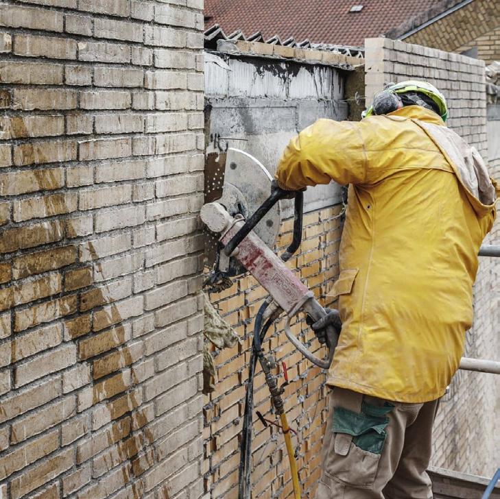
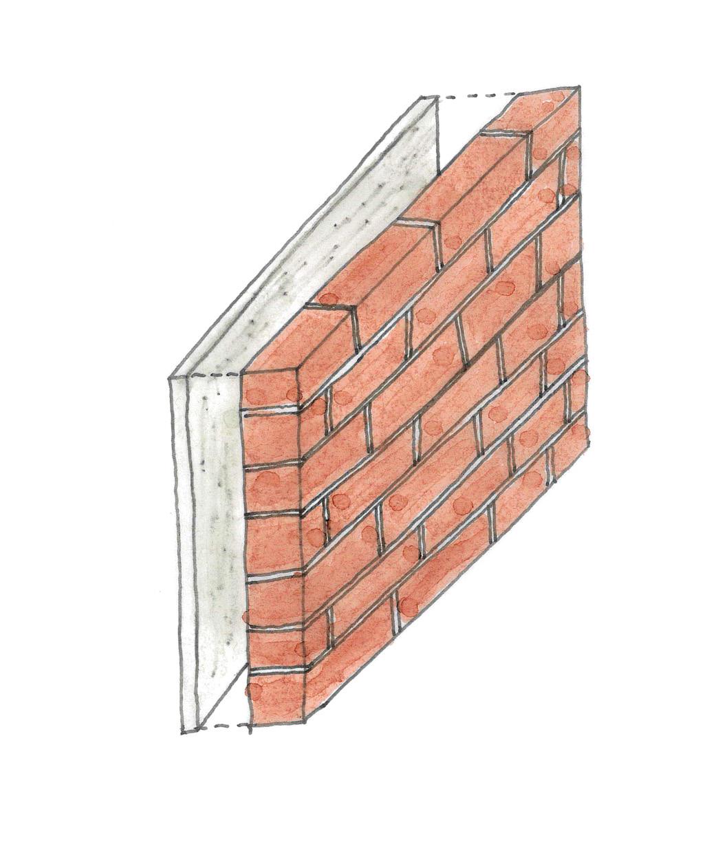
Brick panels are cast onto 25mm concrete slabs to provide further support, before being lifted into position. This method ensures a reuse rate of <90%, whereas striking mortar from individual bricks would yield a reuse rate closer to 50%.
Figure 12: ‘Resource Rows’ by Lendager Architects in Copenhagen is the first project to use this methodology, with bricks cut into 1x1m squares from vacant buildings in the city Reclaimed Brickwork Panel SketchRoof buildup as Type A shown previously
Acoustic panels fixed between glulam truss as detailed on pg. 92
Precast concrete plank supported on steel angle fixed back to primary glulam structure
Proprietary insulated framing angle providing fixing for glazing and eliminating cold bridge at junction
DPM sealed to glazing frame
Reinforced concrete slab cast to falls towards central drain
Top of concrete pile; insulation and hardcore formed around pile with waterproofing membrane laid over (and sealed around reinforcement bars) before slab is poured
PPC aluminium box pressing to edge of roof behind brickwork
Soldier coursed brickwork to top of brick panels, with DPC laid beneath lapped and sealed back to breather membrane
Brick panels tied back to inner leaf & primary structure with galvanised angle cleats
Wall buildup as Type E shown previously
Cavity tray laid across cavity and beneath base of brick panel, with upper section lapped and sealed to breather membrane
Galvanised steel lintel supporting base of brick facade, fixed back with galvanised struts to primary structure, incorporating a proprietary thermal break plate to remove cold bridging
Bespoke brick slip lintel fixed back to galvanised struts, formed in 500x1000mm panels with brick orientation coordinated with panels above
Gravel filled border to edge of paving
Repurposed precast panels fixed to starter bars protruding from slab toe, with high density XPS insulation beneath panels
Integrated Environmental Principles
The Closed Loop
The environmental strategies work in tandem with each other and compliment the manufacturing processes within to facilitate a closed loop system; where nothing is wasted and everything has a purpose.
Maximising Biodiversity Gains
In a context of concrete and car parks, the scheme maximises biodiversity gains across the site to act as an exemplar project for later redevelopment across Swindon.
A Sensitive Retrofit Strategy
The existing building has been retrofitted with best practice in mind, using techniques that work harmoniously with the existing construction. Minimal demolitions have been proposed but those that have make the building work as efficiently as possible.
United Nations Sustainable Development Objectives
achieved by this project
Researching, developing and implementing clean energy production from waste products which could be scaled for wider industry use.

Promoting sustainable, clean and circular energy infrastructure with waste products as the main producer.
Adaptive reuse of an existing vacant building which will help to repair a fractured community for years to come. A focus on material reuse is fostered in the proposal, with the operation of the brewery and restaurant focusing on locally grown ingredients and the reuse of waste products.

The technology and methodology proposed helps to minimise carbon emissions and create clean energy from an unwanted waste product.
A Zone Based Approach
Being arranged around a number of processes, the building lends itself to a zone based approach; environmental strategies tailored to the specific requirements of the processes occurring within each zone. At a high level, these zones are:
Zone 1:
Shop, Lobby & Exhibition (0), Community Brew Space (+1)
Focus on natural ventilation with local mechanical extracts, naturally lit. Existing fabric retrofitted with new insulation with UFH to new floors.
Zone 2:
Taproom & Restaurant (0/+1), Kitchen, Plant and Stores (-1)
Natural cross ventilation with high level vents, with MVHR backup for winter conditions. Existing fabric left uninsulated with high performing roof, floor and glazing to offset losses. Naturally lit from clerestory glazing.
Zone 3:
Brewhall (0)
Naturally lit from North facing rooflights with artificial task lighting as required. Full MVHR system in action throughout the year, with openable rooflights for purging as needed. Unconditioned space; no additional heating required.
Zone 4:
Power Generation Plant (0), Labs (+1)
Ground floor spaces artificially lit due to lux requirements of maintenance tasks occurring. Upper floor spaces naturally lit from North facing rooflights with artificial task lighting. Underfloor heating. Full MVHR system in action throughout the year; openable rooflights to labs for purging as needed.
Zone 5:
Hydroponics (0)
‘Black box’ space with highly controlled internal environment. Artificially lit, controlled by MLA to maximise hop growth. Full MVHR system to maintain internal air quality. Ground coupled to maintain consistent internal temperature (~16oC).
Servicing Strategy
With a more intense servicing requirement than most buildings due to its process driven nature, having clear service routing and generous risers is crucial to the operational success of the proposal. This is, in itself, often a difficult task - only compounded when working with an existing, Listed building which doesn’t take kindly to being knocked around.
The overall strategy for the proposal is to split servicing into three sections; each with its own riser, plant space and independent service runs. Whilst things like small power, data, sprinklers and DH/CW will be shared through the building, this strategy ensures bulky ventilation ductwork is kept contained and removes unsightly alterations to the Listed building as a result.
Section 1 comprises the existing Listed building, with a large plant room located in the existing basement. This plant space would also hold all small power, sprinkler tanks, DH/CW supplies and other plant which can easily be shared between different parts of the building. The riser is located in the North East corner, pulling in fresh and exhausting dirty air through an ‘active corner’.
Section 2 comprises the bulk of the new build elements, with ventilation ductwork serving the brewing hall, labs and power generation spaces. Ventilation plant equipment is located within the South Western tower, which also includes a large riser.
Section 3 comprises of the hydroponics hall and adjacent staff spaces. With the hydroponics hall requiring different, and more tightly controlled, environmental conditions, having ventilation ductwork specifically isolated from the remainder of the building keeps operational aspects simple.
The prevailing winds from the South create a small area of low pressure on the North face of the roof, helping to draw out dirty air.
Retrofit Strategy
Zone 1
Due to the age of the existing Old Town Hall and its method of construction, the approach to insulating the existing fabric must work with the current wall construction to regulate moisture, rather than against it. Historic buildings remain dry and free of damp by ‘breathing’; the walls absorbing moisture from the inside which is then evaporated away on the external surface.
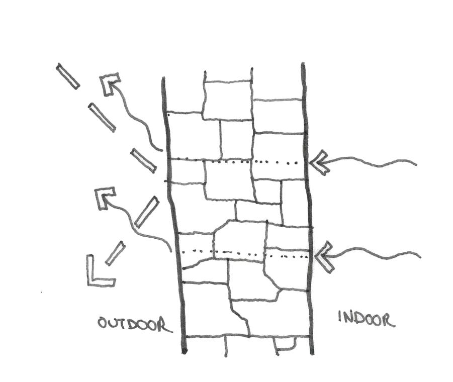
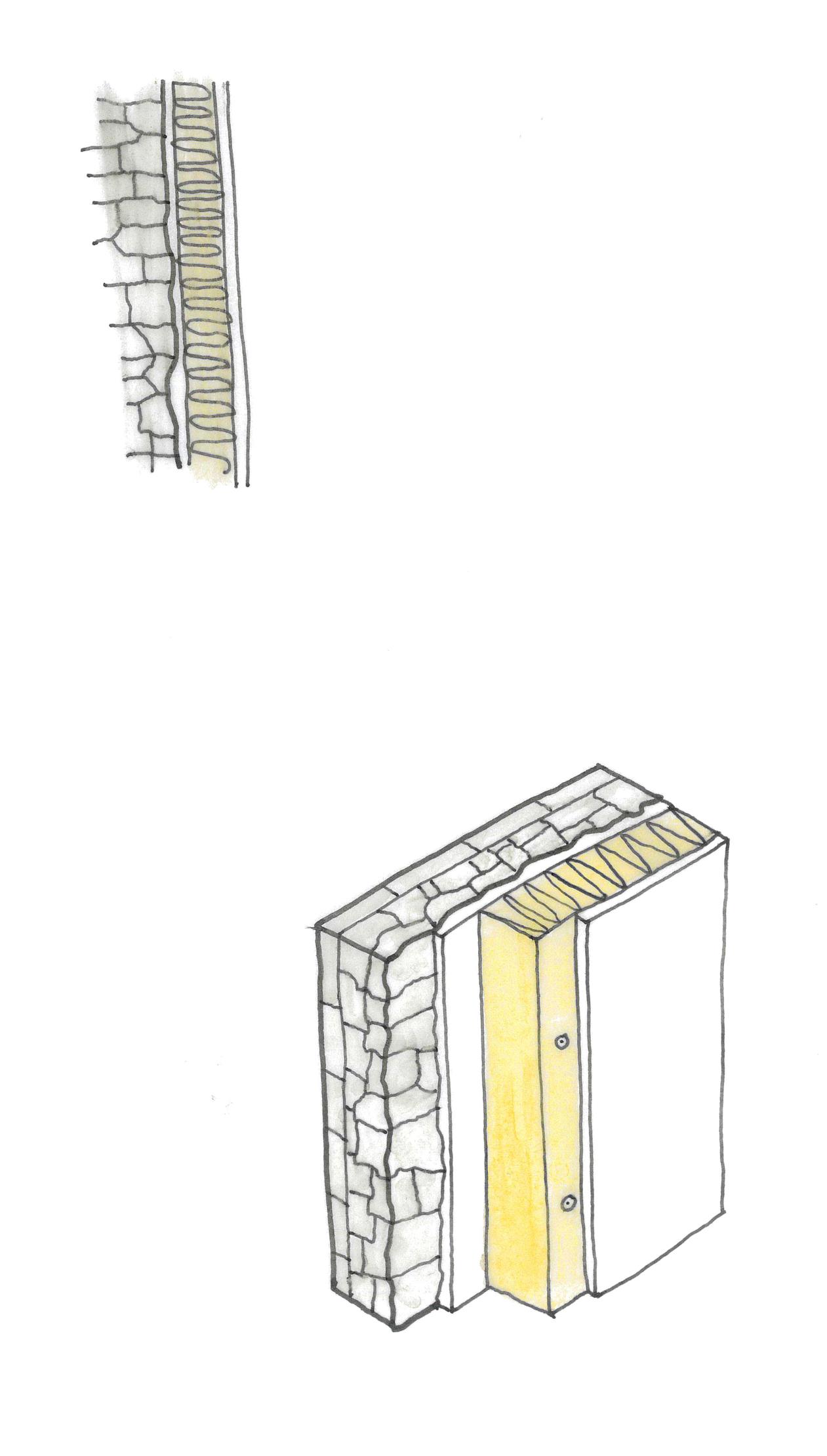
Contrary to the modern approach to fabric efficiency which requires high performing, vapour closed construction to retain heat within the building, fabric upgrades to existing buildings must be ‘breathable’; using vapour open, fibrous insulation products and lime based plasters (known as natural hydraulic lime, or NHL).
Insulation can also not be installed to similar thicknesses or reach equivalent U values as modern constructions due to the increased risk of interstitial condensation - the process where vapour condenses into a liquid as it cools whilst passing through an external element, and leads to damp, rot or freeze/thaw blowout. It is assumed that a full condensation risk analysis would be carried out on the proposed upgrades prior to construction, with the strategy reviewed in light of this information.
Upgraded Solid Wall Buildup
Calculated in accordance with BR443 d
Existing Stone Wall (Limestone)
NHL Levelling Compound
Wood Fibre Board
NHL Plaster
NHL Finishing Plaster
External Surface Resistance
Internal Surface Resistance
The existing stone wall has a calculated U value of increase on the fabric efficiency of the wall.
These insulation upgrades will be applied to the Old Town Hall building and the basement of the Corn Exchange. The upper floors of the Corn Exchange (which house the taproom and restaurant) will be left in their current form - the stone left exposed. This is to ensure the character of the existing Listed building is maintained. The proposed roof (U value 0.11 W/m2K) and upgraded basement walls and floor will offset heat losses from the exposed stone walls.
This proposal, whilst not the most effective in terms of reducing operational energy, is seen to be the most sensitive to the Listed fabric of the building - Part L making Listed Buildings exempt from fabric upgrades where installing insulation would “unacceptably alter the building’s character or appearance”[32]
The Taproom
Zone 2 - Summer Condition
High levels of natural light is provided during daytime occupation by the clerestory glazing. Hanging pendant lights provide ambient lighting during night-time occupation, with higher lux levels of approx. 300 lux over the bar area for task lighting.
Solar shading is not proposed to these clerestory elements as the high levels of natural ventilation will cool the space faster than any solar gains will warm it.
The space is naturally ventilated with opening doors and slim profile trickle vents providing inlet air from both sides of the building.
Hot air rises into the roof space and is exhausted through ventilation ‘grilles’ in the North and South gables.
Underfloor heating powered by ASHP’s installed in the new ground and first floors provides cooling (using cold water cooled by radiators placed in the tower) or top-up heating as required. Due to the high occupancy of the space heating during summer months will be negligible.
Localised MVHR extraction within the prep kitchen to exhaust dirty air and cooking smells.
The existing stone walls have been left exposed to maintain the character of the space, in line with the wider retrofitting strategy and in respect to the Listed nature of the building. The basement walls, floor and new roof elements will be designed with high levels of fabric efficiency to compensate for heat losses through the existing stone walls.
‘Woodwool’ panels mounted between the glulam trusses manage both acoustics and indoor humidity.
During the shoulder seasons, a hybrid of the systems displayed over this spread is proposed, allowing passive and mechanical systems to be blended to ensure optimal user comfort dependant on daily conditions.
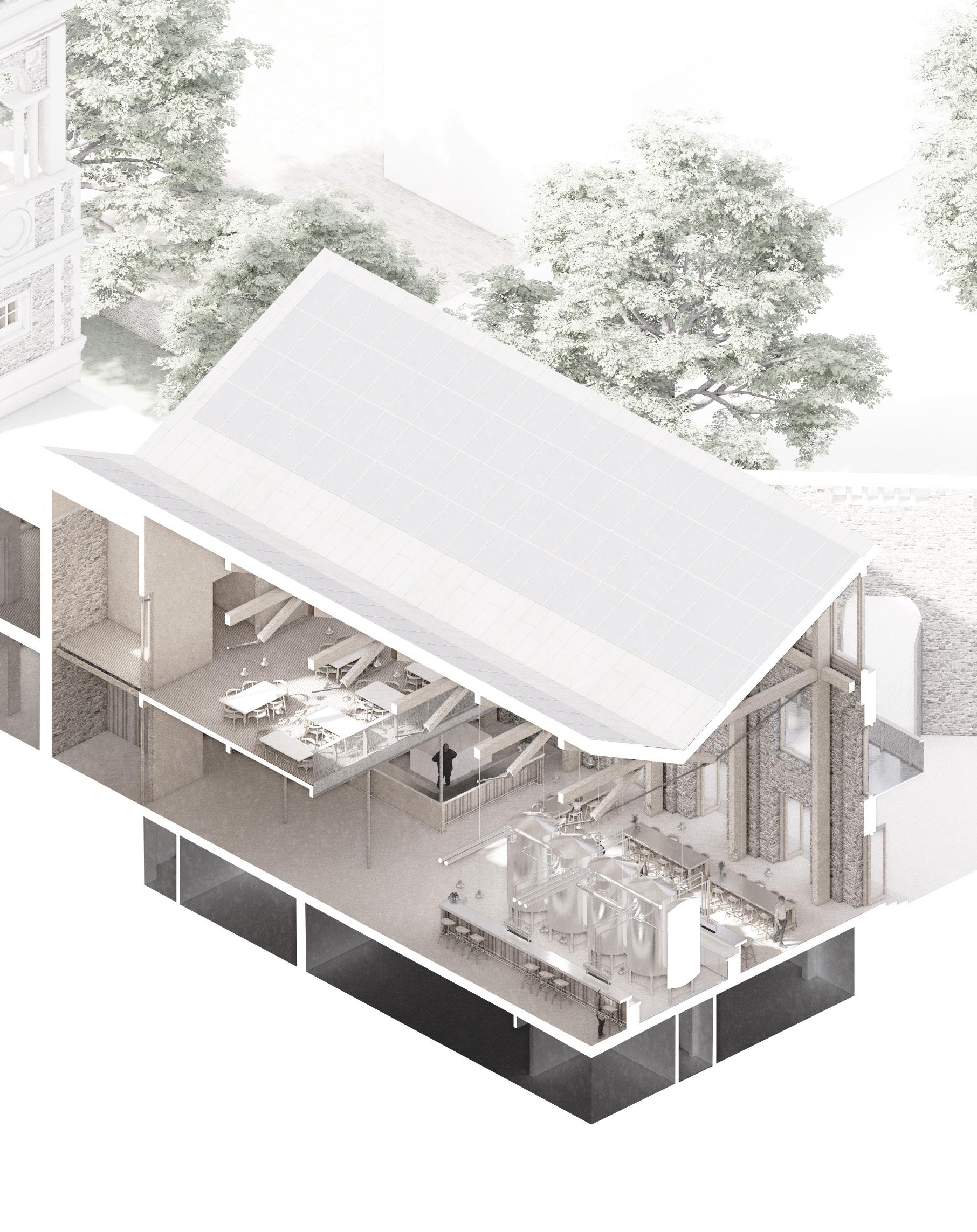
The Taproom
Zone 2 - Winter Condition
High levels of natural light is provided during daytime occupation by the clerestory glazing. Hanging pendant lights provide ambient lighting during night-time occupation, with higher lux levels of approx. 300 lux over the bar area for task lighting.
Solar gains from East and West facing glazing provides passive solar heating.
Mechanical ventilation takes over in the winter, with a full MVHR system located in the basement and ductwork concealed within the service ‘block’ at the North end of the hall. Air is drawn in and exhausted through an ‘active corner’ at high level, linking to the main riser in the hall. Incoming air can be pre-heated as required.
Underfloor heating (powered by ASHP’s) installed in the new ground and first floors provides space heating.
The existing stone walls have been left exposed to maintain the character of the space, in line with the wider retrofitting strategy and in respect to the Listed nature of the building. The basement walls, floor and new roof elements will be designed to high performance levels to compensate for heat losses through the existing stone walls.

Brewing Hall
High performing insulated fabric (U values of 0.14 W/m2K to walls, 0.11 W/m2K to roofs, 0.16 W/m2K to floors) to minimise heat loss and create a stable internal environment.
Diffused natural lighting provided by North facing windows within sawtooth roof, resulting in minimal glare to working areas below.
Cantilevered First Floor provides solar shading to large extents of glazing at Ground Floor level during summer months, preventing overheating. Vertical projecting screens provide shading to First Floor windows during summer months.
Hanging artificial task lighting provided throughout the space to give consistent working plane lux levels of 300 lux[33]
Heat gains within space are primarily due to the brewing vessels; as a result the Brewing Hall is thermally unconditioned (although well insulated) to prevent any compounding of ‘equipment’ heat gains with building heating gains.
Fresh air supplied and stale air extracted via a high efficiency MVHR system located within the adjacent tower. Incoming air can be pre-warmed or pre-cooled as required - pre-cooling more likely year round with pre-heating only required during winter months due to heat gains from equipment.
North facing rooflights can be opened manually to naturally vent the brewing hall if required, especially during summer.
‘Woodwool’ panels mounted between the glulam trusses and over internal finishes manage both acoustics and indoor humidity. With the brewing process involving heating water for long periods of time and on a large scale, humidity is a key concern. Managing this naturally helps to take load off of the MVHR system, resulting in reduced energy use.
As the space is designed to suit a key singular process, the environmental conditions are designed to be similar all year round to provide a consistent working / manufacturing environment. User controls will be provided to enhance occupant comfort on a day by day basis.
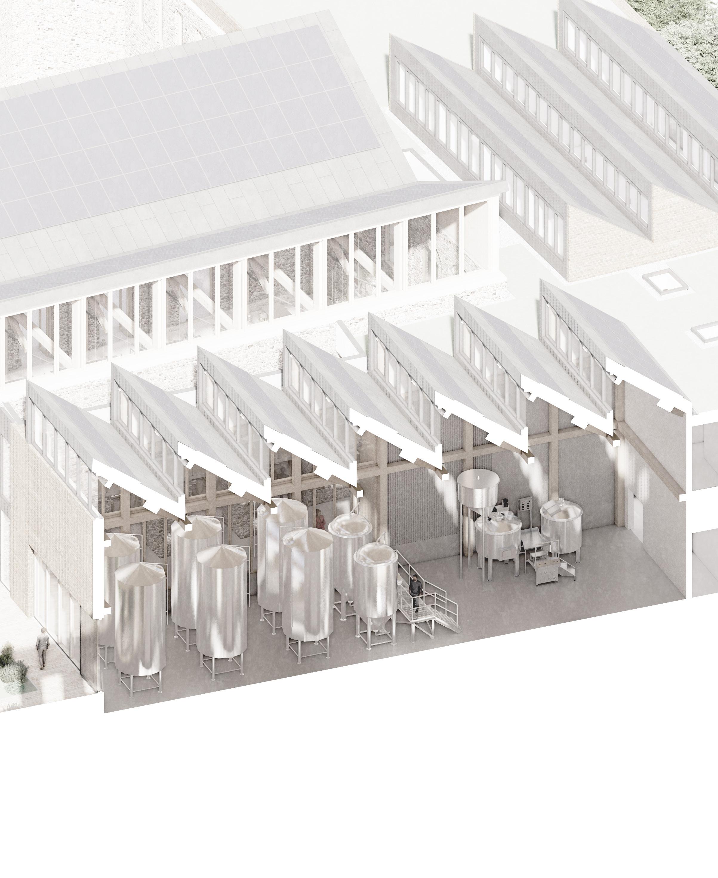
High performing insulated fabric (U values of 0.14 W/m2K to walls, 0.11 W/m2K to roofs) to minimise heat loss and create a stable internal environment.
Diffused natural lighting provided by North facing windows within sawtooth roof, resulting in minimal glare to working areas below.
Structural glass rooflight adjacent to existing wall of Corn Exchange provides diffused bounced lighting into circulation and observation spaces below.
Projecting horizontal screens provide solar shading to South facing windows.
Artificial task lighting provided throughout the space to give consistent working plane lux levels of 500-1000 lux (for detailed tasks and maintenance activities).
Underfloor heating buried in floor screeds (powered by ASHP’s) to provide consistent and controllable low temperature space heating or cooling, powered by ASHP’s.
Fresh air supplied and stale air extracted via a high efficiency MVHR system located within the adjacent tower. Incoming air can be pre-warmed or pre-cooled as required to supplement underfloor heating.
North facing rooflights above the labs can be opened manually to naturally vent the space if required, especially during summer. 8
‘Woodwool’ panels mounted between the glulam trusses and suspended beneath precast planks (to maintain thermal mass of intermediate floor; providing benefits to acoustics and indoor humidity as discussed previously).
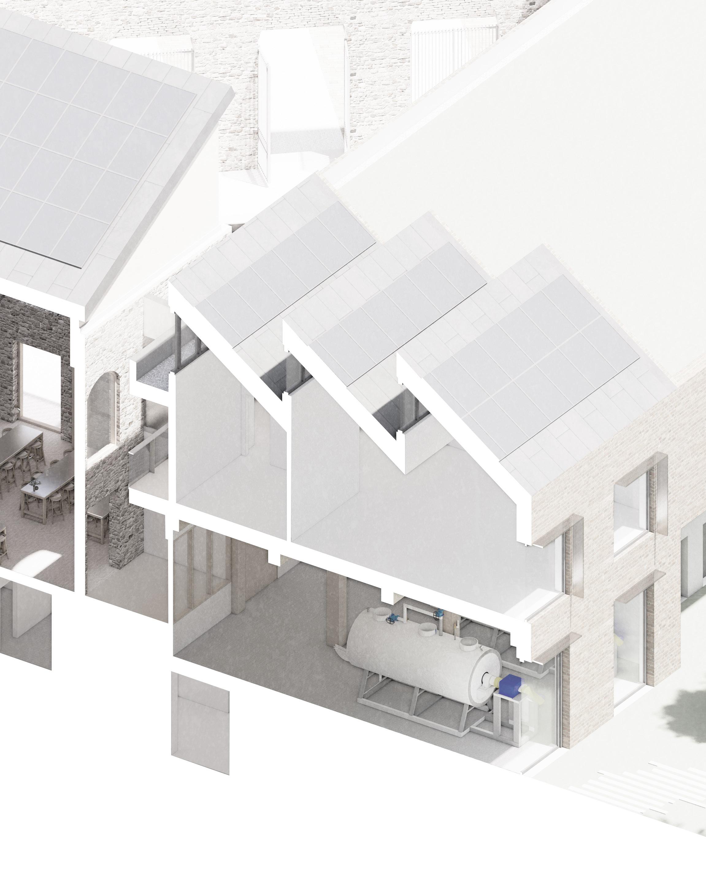
High performing insulated fabric (U values of 0.14 W/m2K walls, 0.16 W/m2K roofs) to minimise heat loss and create a stable internal environment. Shear wall between hydroponics hall and stair core / staff spaces also insulated, with lobbied doors between key spaces.
Ground coupled floor slab to maintain consistent internal temperature of 16oC.
Full crossflow MVHR system with heat exchanger to ensure consistent, controlled internal air quality. Plant room located near to hydroponics hall to minimise duct runs. Fresh air inlets and dirty air outlets located on flat roof above.
Artificial lighting linked to ‘machine learning algorithm’ system which automatically adjusts artificial lighting on a grid basis to offset or compliment any natural lighting to create optimal growing conditions for hops.
Hydroponics utilise UV treated rainwater collected from roofs on site.
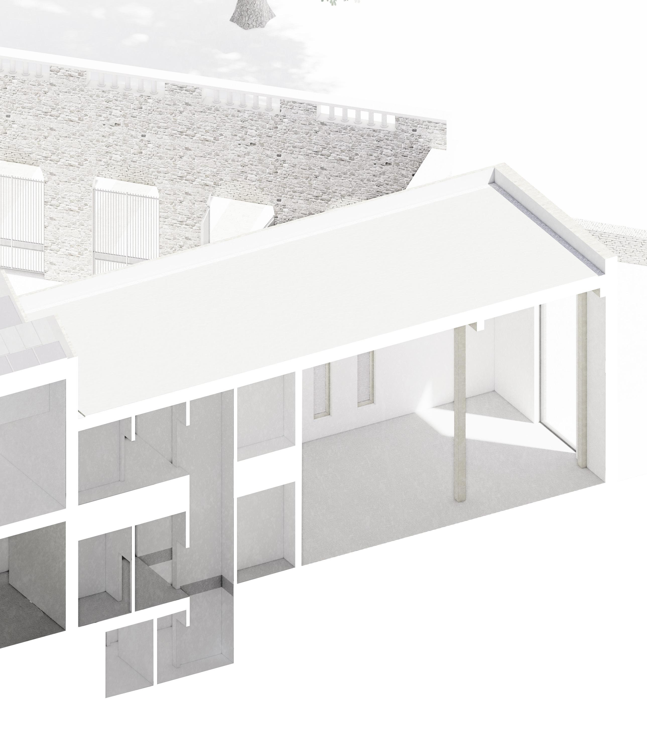
Optimising the Basement
Working with existing buildings always brings compromises and difficulties, due to the constraints of the existing fabric. This is especially true environmentally, where buildings were not designed in the same ways as today. Breathing new life into historic vacant structures often requires re-purposing them to suit new and different uses, which results in old buildings being occupied by new spaces they were never designed to serve.
This is most true in the basement of the scheme, which contains (amongst other spaces) the prep kitchen for the restaurant and taproom above. Whilst making the most sense from a spatial organisation standpoint, it does bring some unique environmental challenges - namely those of lighting and ventilation.
Preliminary Kitchen Ductwork Sizing
In accordance with Approved Document F
With the service riser being approximately 1.2m x 2.3m, 2 no. 300mm ducts can easily be accommodated, with more than adequate room for ducts etc. serving other spaces within the plan.
It is anticipated that lighting will be artificial (using low energy LED’s), due to the need to provide task lighting on the working plane of 500 lux. However, to provide some background natural light a sequence of lightwells have been pushed down into the rear of the kitchen, receiving stolen light from the observation deck above.
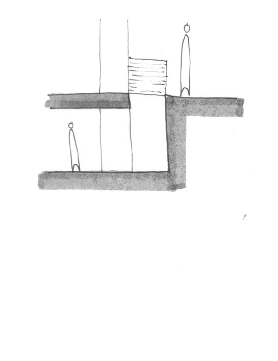
Light wells providing ‘stolen light’ from observation deck above. Structural glass laid over aperture to seperate spaces acoustically and prevent transmission of smells etc.
Acoustics
With a number of larger scale, double height spaces throughout the project, acoustics are a key concern to ensure suitable auditory environments are maintained throughout. In the absence of specific standards for room reverberation times (outside of BB93 for schools), a set of best practice values have been used to inform the acoustic design of the spaces[34]:
Labs, Offices & Staff Spaces
Given the exposed structural materials present in the new build elements (CLT, precast floor slabs, concrete floors etc.) and the existing stone walls in the taproom, acoustic cassette panels will be suspended from ceilings throughout to help reduce reverberation times to acceptable levels. Being suspended, any thermal mass prevalent in the floor construction is still effective.
A typical buildup for these panels is shown below, which incorporates a ‘wood wool’ panel on the outer face. As well as dealing with acoustics, these hygroscopic panels also help to regulate internal humidity[35]extremely helpful as humid manufacturing processes occur in two key areas of the building.
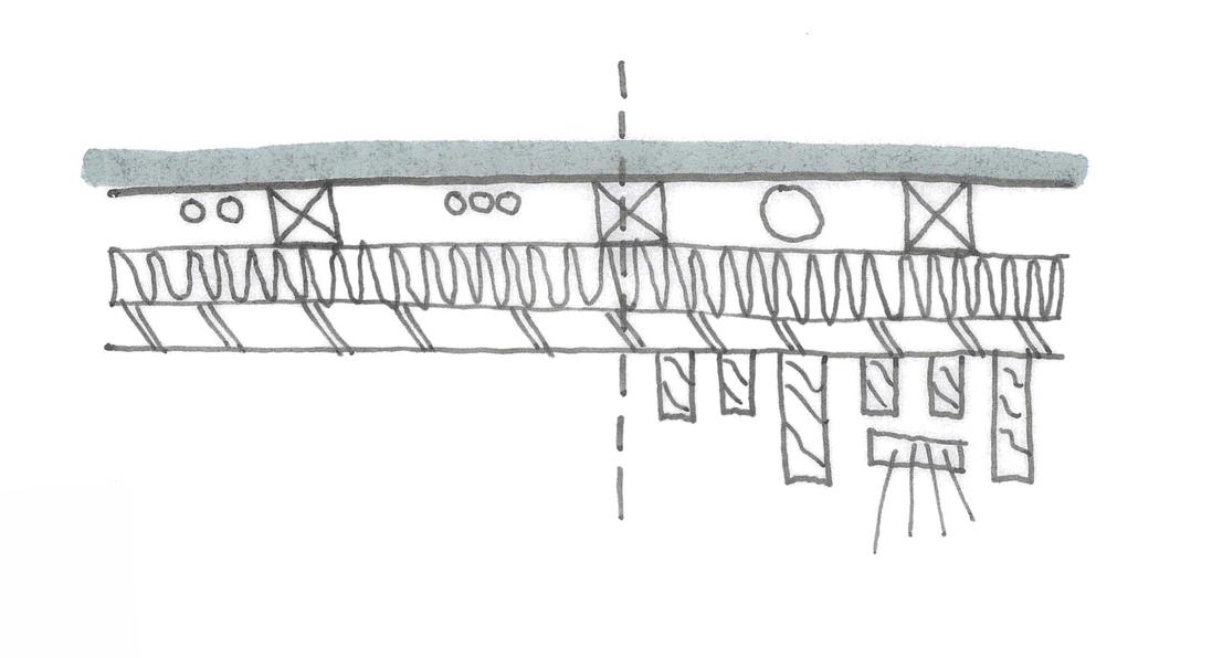
Bespoke Acoustic Panel Section
Being the largest space in the proposal with the greatest acoustic challenge, a simplified calculation was carried out on the taproom to approximate the extent of acoustic panelling required to ensure a reverberation time in line with the specification could be achieved (utilising the Sabine Equation). Note that this calculation does not take into account the effect of people/clothing, which would reduce the time further.
38x38mm battens forming service void for small power, data etc
25mm acoustic insulation batts for further acoustic dampening 25mm woodwool board
Larch battens fixed perpendicular to acoustic panel to provide rhythm to ceiling in public areas
Recess allowing for LED strip lighting
Section A-A Extract
Extent of acoustic panels shown red (to ceiling and high level N/S panels)
Lighting
The varying spaces within the proposal and the processes they house each require differing lighting conditions, with the design of the proposal helping to facilitate these. The manufacturing and laboratory spaces, for example, have a lux requirement of 500-1000 lux and require consistent, diffuse daylighting (i.e no shadows); hence the introduction of North facing rooflights within the sawtooth roofs above.
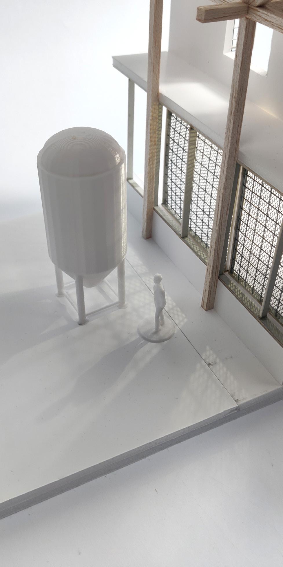
To mitigate solar gains, mesh screens have been installed on all windows to provide shading from the high altitude summer sun, whilst retaining solar gains from the lower winter sun. On the South elevation, these shading devices are continued down the East facing edge of windows to reduce early morning glare into the lab spaces behind.
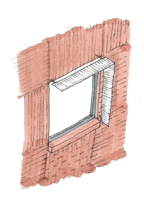
Due to the high illuminance requirements of the manufacturing spaces, artificial lighting will be specified in these areas - but this will be solely task lighting to illuminate the working plane. All lighting will be low energy LEDs. Artificial lighting will also be required within the public spaces due to the operating hours of the building often being outside of daylight hours.
With that being said, lighting can also be used as a dramatic tool, which the building aims to do by incorporating a play of light and shadow within key spaces and to the elevations.
Spatial Illuminance Requirements:
Taproom, Restaurant & Public Spaces
Taproom Bar
Laboratories & Kitchens
Brewing Hall
Staff Spaces, WC’s etc.
Seminar / Meeting Rooms

Fabric Efficiency
External Wall - Brick Panel Cladding
Roof - Standing Seam Zinc Cladding
Calculated in accordance with BR443 Calculated in accordance with BR443
The proposal has an overall form factor of 2.4, which is within Passivhaus recommendations of 3 and very compact given the nature of working with an existing building.
For the roof buildup calculated above, the standing seam and plywood board have negligible impact on the overall U value as they are separated from the remainder of the construction by a ventilated void, and so have been discounted.
The typical buildup for retrofitting the existing Town Hall has been shown previously, utilising natural insulation materials and breathable construction. The main entrance tower is outside of the thermal envelope.
The Tower
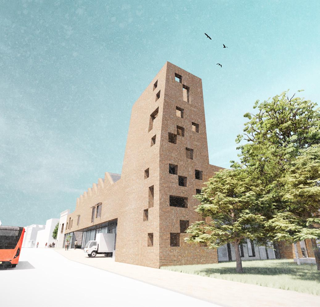
The proposed tower acts as both a visual and environmental anchor for the scheme, providing a host of passive environmental benefits. Being the element with the most visual ‘weight’, it is crucial that this element works extremely hard to justify its inclusion beyond that of a purely architectural move.
Being located on the South West corner of the scheme, the tower is in optimal position to take advantage of the incoming prevailing wind. With the incoming winds passing over the top of the open tower, a negative pressure zone is created, which in turn draws air up from the bottom of the tower to fill the void.
This passive airflow can be harnessed to achieve several aims, principally relating to passive cooling of the building. Along with primary intakes and exhausts for the MVHR system, panels of small diameter pipe and duct arrays are placed within the tower to pre-cool incoming air or cool the water based underfloor heating system - all without using any energy.
Exhausts for MVHR system and lab / brewing hall secondary extraction systems at top of tower stack (preventing contamination with fresh air intakes below)
Primary intake for crossflow MVHR ventilation system behind cut plane
Small diameter duct array to passively cool incoming fresh air
Water filled panels to cool the underfloor heating system during summer months
Holes punched in brick panel facade to allow inlets for incoming clean air at low level. Bases chamfered inwards to prevent water ponding on cill
Enhancing Biodiversity
The scheme places biodiversity at the forefront, aiming to ‘give back’ to the site and adjacent public realm by maximising biodiversity gains across the site, in line with the brief aspirations. The various interventions are discussed below which help to facilitate these gains:
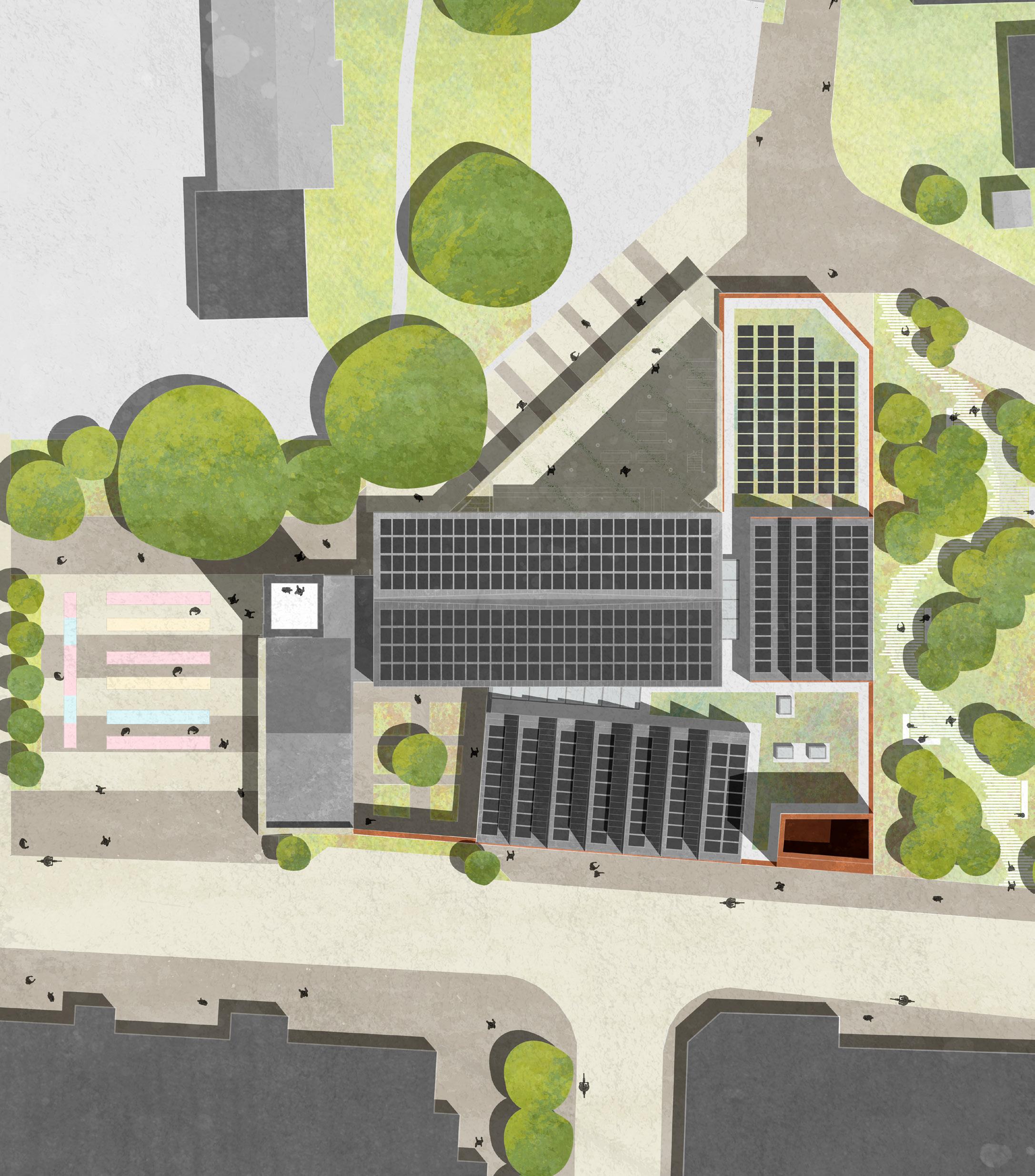
New planting to various landscaped beds around the reinstated courtyard, along with enhanced tree planting. Planting specification will focus on pollinators and plants that improve air quality; helping to filter vehicle fumes from the adjacent road.


Birch Ferns Scabiouses Flower
A focus on herbs, flowers and fruits which can be used within the brewing process (experimentally or otherwise). The mesh screens give purchase for climbing hop vines. Planting will be more rotational than other zones, growing produce suitable for the relevant season.
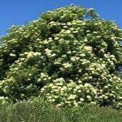


Elderflower Rosemary Juniper
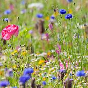
The primary intent of this space is to create a new biodiverse corridor to link the new green corridor terminating at the West of the site, with the Lawns to the East. Local tree species will create a flying corridor for bats, with pollinating flowers and tall grasses boosting ecology for ground dwelling species.


Silvergrass Lambs Ear
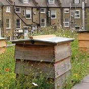
New green roofs will be a mixture of sedums and wildflowers along with experimental grains (for prospective brewing use) and other planting which survive well in shallower growing mediums. Beehives will also be introduced with the honey used in the brewing process.

The Responsible Use of Water
Given the high quantity of water required by the scheme as part of the brewing process, by kitchens and by the hydroponics equipment, the reuse and harvesting of water will be key to minimise mains water use. Unfortunately, given the need to use potable water in items which will be consumed (i.e. beer and food), the kitchens and brewing hall are forced to use mains water, but the remainder of the scheme will endeavour to source its water purely from


A Holistic Closed Loop System
The closed loop system is the beating heart of the proposal. The following calculations and explanation prove its capacity to fulfil the building’s energy demand, based off some assumptions outlined below.
Given the complex manufacturing processes contained within the building, there is no readily available energy use data outside of a complex building performance model. Therefore, the upper end of the LETI standards have been used as a baseline, of 75 kWh/m2/year - this equates to 714 kWh per day. This may be somewhat optimistic, but without more accurate data being readily available, this is a good place to start. The building and processes incorporate several energy recycling methods - including a number of high efficiency heat exchangers and passive ventilation. Developing this proposal more would involve the construction of a full building energy model to test this.
For the quantity of BSG waste, I have assumed that the brewing hall will produce 2500 pints (1465 l) per week, although this may be too low of a figure.
2500 pints per week (1465 l) creates 41.9 kg BSG per day, on average (the brewing process being 2 weeks, plus fermentation);
Hydrogen generation cycle occurs over 40 days; therefore there will be 1676 kg BSG produced over this period.
With 1kg BSG producing 3.9 kWh power over the 40 day period, each BSG batch contains 6536.4 kWh total, or 163 kWh per day
The solar PV array is comprised of 405 panels, each rated to 500W. Using the Swindon conversion figure of 975 kWh/kWp, the array will provide on average 557 kWh per day
Renewable energy from these two sources totals 720 kWh per day; greater than the estimate energy demand of 714 kWh.
The building’s plant room will contain a large battery storage array to help smooth out the peaks and troughs in energy generation.
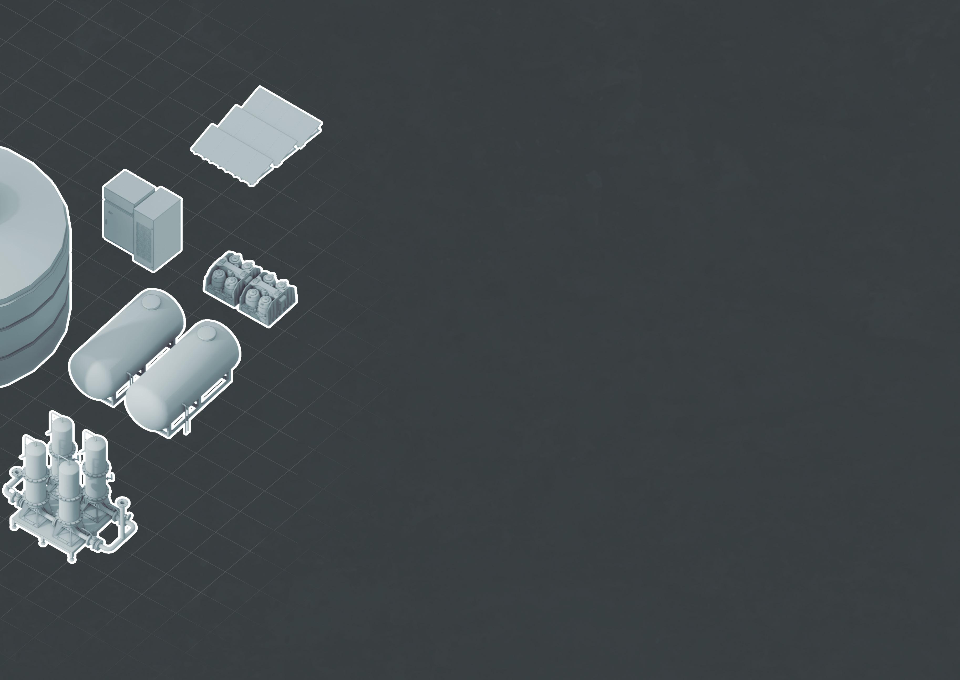
Serving Tanks, Canning & Kegs Pre-treatment Tank Separator Tanks Granular Biomass Reactor Anaerobic Digester Exhaust
Quantifying Further Carbon Savings
With the brewery waste products an integral part of the closed loop system discussed prior, they are no longer sent either to landfill or to nearby farms for use as livestock feed, which has further carbon savings - these are quantified below. These calculations use the same assumptions as previously:
• 5000 pints brewed per cycle (once every two weeks) equates to approximately 1173 kg BSG; naturally there would be a variety of beers brewed at any one time, but these would be in smaller quantities - the wastage figures would be the same. This equates to 602 kgCO2e per cycle, or 16562 kgCO2e yearly.
• Given its relatively short shelf life it would be collected and transported immediately, so there would be approximately 26 journeys per year. The farms shown adjacent are on average 13 miles (26 miles round trip).
• With road transport emitting carbon at 0.17 gCO2e/kg/mile, each trip would produce 5.18 kgCO2e - or 134.8 kgCO2e yearly.
Carbon Savings:
For clarity, these carbon figures below do not apply to this project; they are purely to illustrate carbon savings gained by using waste BSG to generate power, rather than using as livestock feed or sent to landfill.
BSG Waste Sent to Farms:
134 kgCO2e yearly
BSG Waste Sent to Landfill:
16,697 kgCO2e yearly
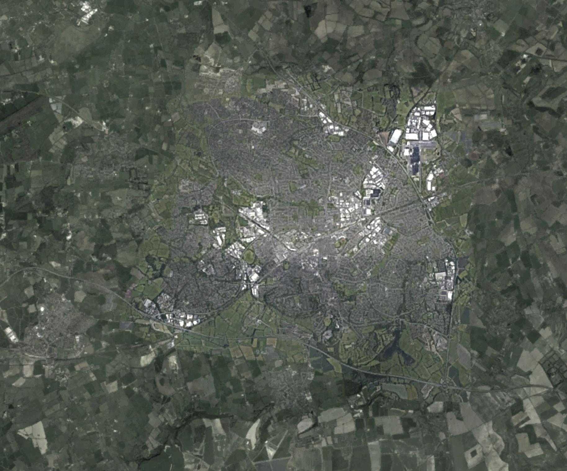
The Future
With the nascent nature of the technologies proposed by the building, and its nature as a place of research and development, its future is somewhat uncertain as it is dependant on the success of its implementation. The projected future given below assumes a successful implementation of these technologies, with the building having acted as a manifesto for the wider implementation of these technologies across the wider brewing sector, which now produces zero operational carbon with power supplied fully from renewable / waste sources.
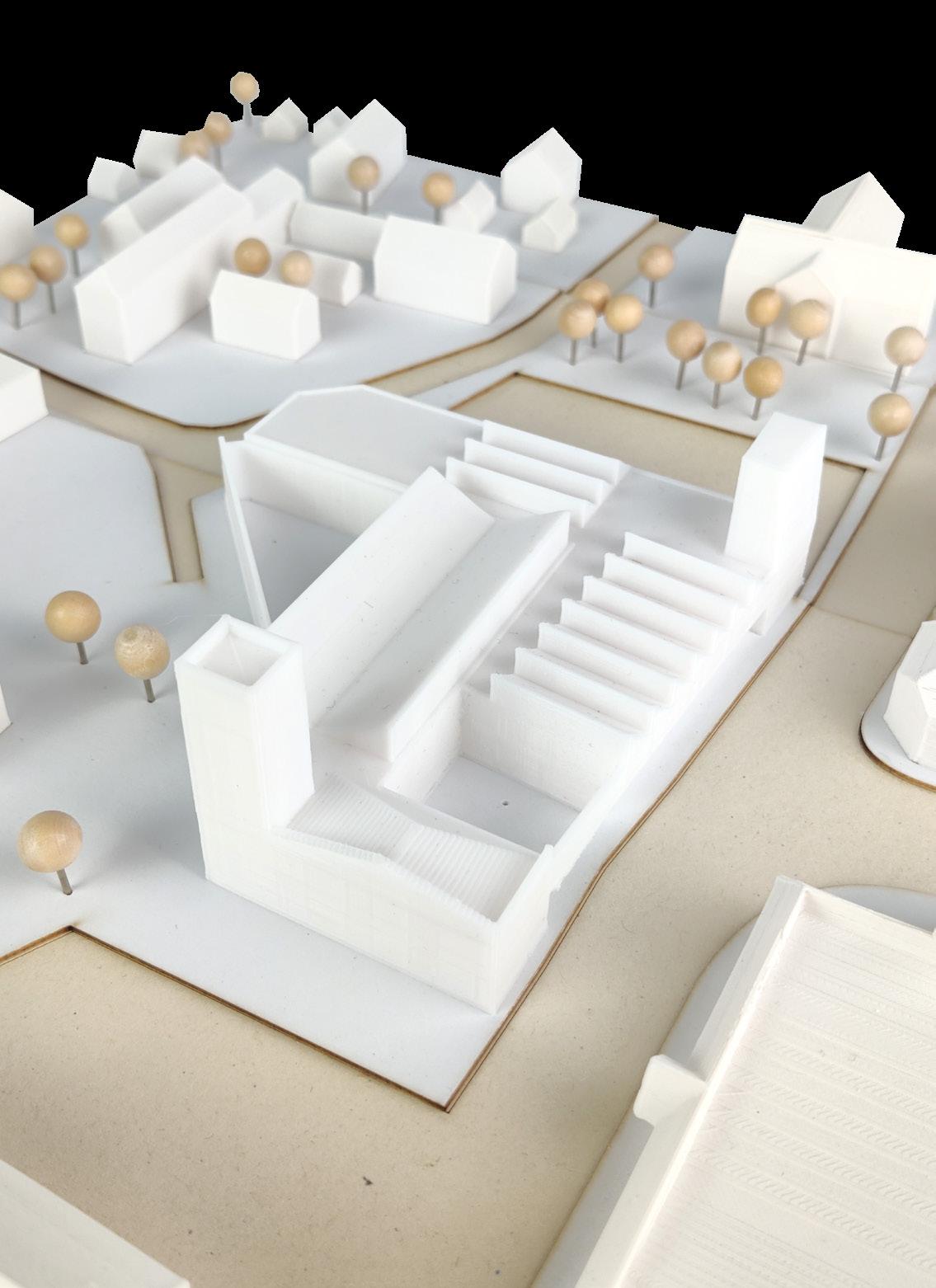
2000 (+150) 2024 (+154)
2130 (+280)
With the disassembly and removal of the ‘new’ elements of the structure, the Old Town Hall is left vacant once more; awaiting a new use. The sensitively designed elements have left little in the way of marks on the existing fabric. Having stood for over 250 years with regular maintenance during its life, it will continue to stand for many more years to come.
2030 (+0)
Dependant on detailed design and construction programmes, the building is handed over in the years preceding 2030, and begins its operation. It operates at zero operational carbon in line with 2030 targets.
2060 (+30)
The implementation of the nascent cyclical technologies are successful, and the scheme has matured - landscaping is fully established and the building has cemented itself in the local community. The building undergoes its first maintenance cycle, with plant equipment (MVHR etc.) replaced as required.
2090 (+60)
Timber structural elements need regular maintenance and repairs. The building has been extended to provide further capacity for brewing and power generation, and has been linked to a district power system providing renewable power to the nearby residential dwellings.
2130 (+100)
Anticipated end of buildings life. Having been designed with disassembly in mind, components are easily disassembled and removed (including the brick panels and glulam structure), and added to local materials stockpiles for use elsewhere. Concrete slabs and basement walls are recycled into new concrete products.
Part B - Fire Safety
B1 Means of Warning and Escape
The building contains 3 primary internal protected cores, rated for 60 minutes fire resisting construction using 2 layers of staggered plasterboard or equivalent, and which all provide direct access to a place of safety externally. Designated assembly points would be located in the North square, and to the South East or South West site boundaries. Smoke vents are located at the top of each protected core.
All escape staircases and corridors are 1200mm wide minimum, and disabled refuges (900x1500mm) are provided at all levels in each core, positioned away from the escape route.
The building will have a fire detection and alarm system, to a minimum Grade D2 Category LD3 Standard in accordance with BS 5839-6:2013, with mains wired smoke and heat detectors to BS EN 14604:2005.
A fire curtain is positioned in the Ground Floor exhibition space in the Old Town Hall, to allow this space to act as an escape route for the basement level below.
B2, B3, B4 Prevention of Fire Spread
Materials specification both internally and externally will be compliant with the relevant standards to prevent surface spread of flame. Timber surface finishes internally will be treated with suitable clear-coat fire resistant paint to achieve the required B-s3, d2 according to Table 6.1.
The building will be fitted throughout with an automated sprinkler system fixed at ceiling level. All walls & floors to cores and compartments will be designed to provide 60 minutes fire resisting construction, with any glazing in these areas similarly rated for both integrity and insulation.
Exposed glulam structure will be designed to incorporate an outer char layer to provide 60 minutes fire resistance, to be reviewed and confirmed by a Fire Engineer.
N.B: The specification of partitions, linings and glazing to hydrogen storage are (i.e. place of special fire hazard) would require consultation with BCO, HSE and fire engineer to confirm as ‘building scale’ hydrogen storage is not covered by any current regulations.
B5 Access for the Fire Service
Access for the fire service is possible to all sides of the building, with principal access via either the Square to the North, the delivery bay along the adjacent B4006, or via the delivery turning zone to the South East.
Dry fire mains will be provided in all cores in accordance with BS 9990.
5 no. fire hydrants are present within 45m of the building, so the introduction of new hydrants are not required (https://dataservices.riscauthority.co.uk/map/index).
Summary of Escape Distances Key
Protected stairways
High risk spaces (place of special fire hazard)
curtain
travel distance
Generally: 18/45m
Industrial (Brewing): 25/45m
Plant Rooms: 9/35m
High Risk Spaces: 9/18m
Part M - Accessibility
Sections 1 & 2 Access to and into Buildings
Access to the building from the boundary of the site is level and requires no new ramps or steps. The existing steps between the East courtyard and taproom are retained, however level access is provided via the nearby entrance to the North.
Disabled parking will be located to the South side of the site, adjacent to the new biodiverse corridor. The parking bays and subsequent route to the building will be designed in accordance with paragraph 1.13 of A.D M.
External access doors to the new building elements will have a clear width of 825mm (in accordance with Table 2), with level thresholds and a covered space of 1500 x 1500mm externally.
Section 3 Horizontal and Vertical Circulation
All corridors are minimum 1200mm wide along their entire lengths, with 1800mm square wheelchair passing points at suitable locations.
New passenger lifts are provided in each zone of the building, typically adjacent to stair cores. These are sized in accordance with Diagram 11 (min. 900 x 1500mm) with an unobstructed turning space of 1500mm x 1500mm in front of lift doors.
All staircases are designed in accordance with Approved Document K (and are therefore compliant with A.D M), being 1200mm wide with 1000mm clear distance between handrails. Handrails are positioned between 900-1000mm above the step line of the flight.
Section 4 Facilities
This section is not applicable to this project.
Section 5 Sanitary Provision
Unisex wheelchair accessible W.C’s are provided to all floors in the locations noted on the plans adjacent, with a minimum size of 1500 x 2200mm (in accordance with Diagram 18). Where possible, these are positioned in similar locations on each floor. A higher provision than normal is provided due to the building’s use as a bar and restaurant.
A changing places W.C is provided in the Old Town Hall, which will be accessible out of hours through the use of a RADAR key.
Passenger lifts (900 x 1500mm min.)
Accessible W.C’s (1500 x 2200mm min)
Part L - Conservation of Fuel and Power
L1 Limiting Heat Gains and Losses
All new and existing building fabric will be designed to surpass the U value limits prescribed in Part L, as highlighted below. Junctions between building elements will be detailed to maintain insulation continuity and airtightness, achieving suitable psi levels. All structure will be thermally broken using proprietary break plates where it passes through the thermal line (i.e. in the Vierendeel Truss supporting brick wall to the West elevation).
Existing building elements will be upgraded with new breathable insulation and finishes to achieve U values surpassing the limits set in Approved Document L. Any new insulation upgrades to existing fabric will be balanced against any condensation risk posed by the upgrade works.
Summary of U Values of New and Upgraded Elements
New External Walls
Pitched Roofs
Flat Roofs
Floors
Upgraded Walls
Upgraded Floors
Glazing
Fabric Airtightness of New Elements
0.14 W/m2K
W/m2K
W/m2K
W/m2K 0.27 W/m2K 0.3 W/m2K
0.9 W/m2K
~1.0 m3/(h.m2) @ 50Pa
(0.26 W/m2K Limit)
(0.16 W/m2K Limit)
(0.18 W/m2K Limit)
(0.18 W/m2K Limit)
(0.30 W/m2K Limit)
(0.70 W/m2K Limit)
(1.60 W/m2K Limit)
L2 On Site Generation of Electricity
Coupled with the biohydrogen power generation equipment contained within the building, a generous rooftop solar PV array is proposed to generate further onsite renewable electricity - the extent of which is shown adjacent. Refer to the prior environmental strategy for details and calculations.
Construction, Design and Management (CDM)
01 Pre-Construction
It is anticipated that a full suite of surveys would be carried out on the existing building during the wider design process, encompassing (but not limited to) a full measured, structural, arboricultural and geotechnical surveys. A full suite of existing information will allow the design team to make accurate decisions with construction & operational safety in mind. Formal CDM reviews will be carried out at key stage gates during the design process, with any identified risks logged and corrected.
Whilst a little beyond the scope of this report - it would be preferred for a contractor to be bought on-board at an early stage (i.e. through a two stage tender process or similar), allowing for theirs, and specialist subcontractors, inputs on the detailed design. Full method statements would be prepared ahead of construction by the Construction team with specialist input from a structural engineer, in respect to any demolition or alteration works to the existing building, including the design and installation of temporary propping where appropriate.
A full suite of protection details would be prepared for the existing Listed fabric and to any nearby mature trees in line with relevant British Standards.
02 Construction
The site will be set up in accordance with the diagram below, comprising of:
• Solid hoardings to the perimeter of the site (to prevent dust and debris leaving the site) with a minimum clear width of 1400mm for scaffolding and manoeuvring;
• The site compound would be located within the South Car Park (The Planks), with all required site offices & welfare facilities established. A materials store would be positioned in the South East corner of the compound, with deliveries off the adjacent lane to minimise traffic disruption on the main road.
• Access to the site will be controlled in accordance with best practice, with all required PPE (as deemed necessary following relevant risk assessments) worn at all times.
The building has been designed to utilise pre-fabricated methods of construction where possible, which can be craned into position.
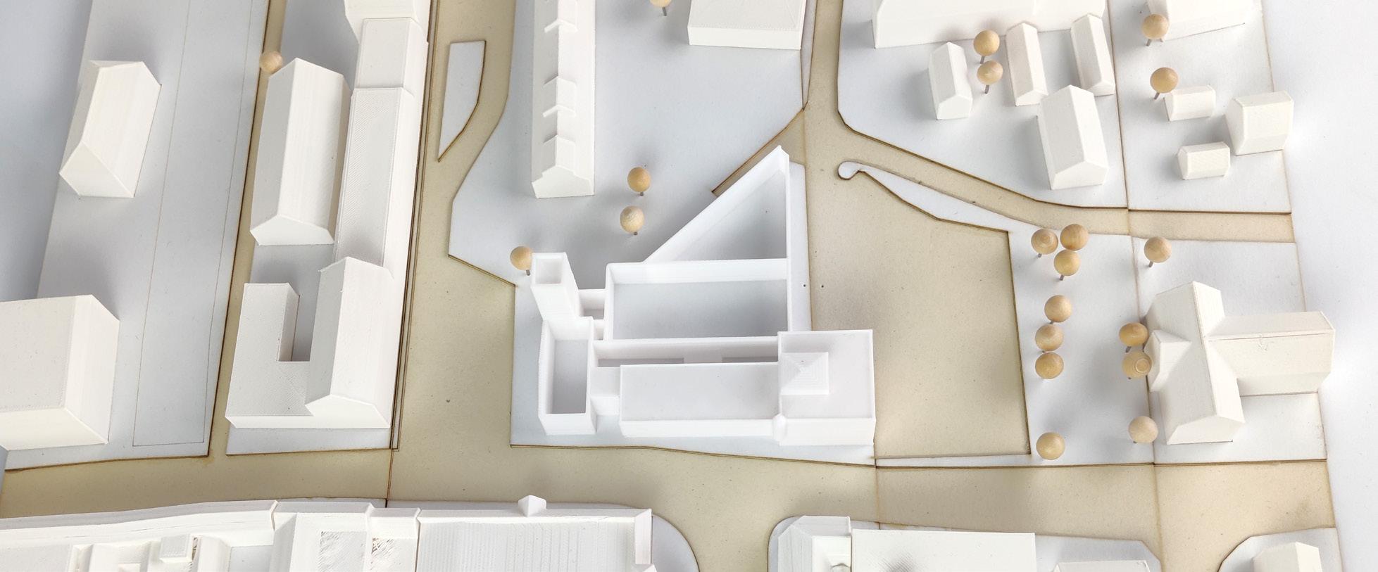
03 Post Construction (Occupation)
All windows and rooflights can be cleaned with long handled water fed brushes either from the flat roof / ground, or via MEWP (carried out by a competent specialist).
A full fall protection system will be installed on the green roofs for safe maintenance.
Valley gutters not easily cleaned from adjacent flat roofs have been designed to be minimum 600mm wide, to allow a person to walk down and clean gutters etc.
Plant rooms are easily accessible to allow for future maintenance of plant equipment.
The building can be easily split into two separate sections to facilitate the differing opening hours of the elements of the scheme. This is shown below:
Kitchen etc.
Initial Aims
From the start of the project, I wanted to develop my skills as a designer by working in ways I had not properly explored before - the longer project allowed for these degrees of experimentation both in design but also in workflow.
Physical Models
Prior to this project I had not fully dived into using physical models in my design process; often leaning towards using digital models. This is somewhat a knock on effect of our first year in COVID, and I was keen to get out of this workflow and utilise this opportunity to further these skills.
I think I overall achieved this aim - not starting with digital 3D models until week 8 or 9 - and I was proud of the models I created (especially the 1:50 tectonic model).
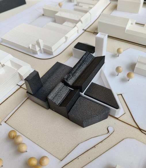
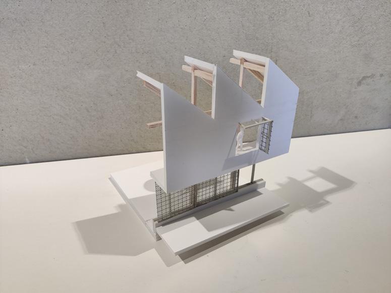
In a similar vein to above, I was keen to keep sketching as long as possible in the process, as I felt it would be helpful in keeping my design process loose and allowing me to explore lots of iterations. In the past, I have had a tendency to jump into ‘detailed’ CAD early in the process - whereas for this project I held off until week 5 (only using rough ‘base’ CAD drawings up to that point).
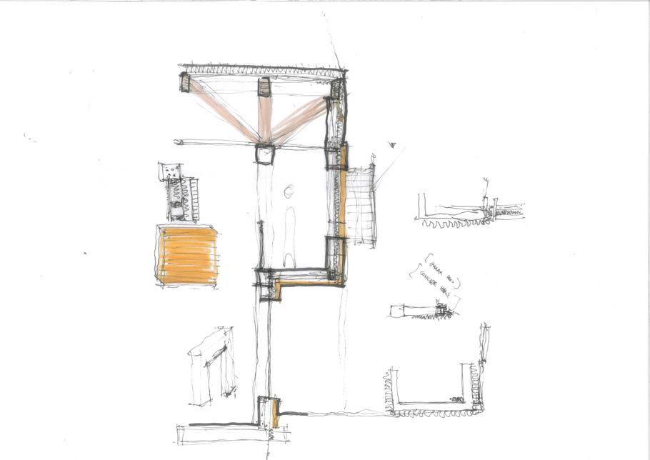
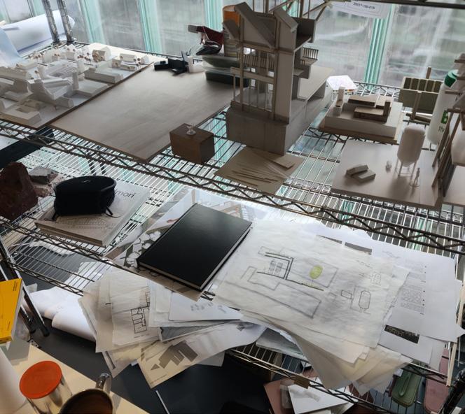
A Note on the Project Structure:
The project is spread over 13 weeks and broken into 5 blocks or sprints; each culminating in a review or submission. The following pages each show a snapshot of each block, with relevant commentary explaining my process and decisions.

Up to Desktop Review
Block 01 - Weeks 1-2
Identifying the Opportunities
Following on from ideas developed in the brief, I began the process by re-highlighting the key constraints and opportunities of the project - including the potential for new routes in and around the site. The existing Listed building was always going to be challenging to work with, but I knew the weaving of new with existing would create a rich, layered scheme.
Developing Options
With this project, it was my intention to try to develop very different options in the first couple of weeks; trying to flip ideas on their heads and not getting too stuck in one line of thinking - something I know I am prone to and a habit I wanted to get out of.
From my initial analysis of the existing building, it felt correct for the public bar/taproom to be positioned in the old corn exchange (the linear, rectangular space). With that as a ‘constant’, I endeavoured to trial a number of options with the various supporting zones arrayed in different ways. Whilst these weren’t always successful, I felt it was a useful process in exploring the project in different iterations. I tested these in sketch form (both in plan and section) as well as with 3D models.
The Question of Adaptive Reuse
Another concern and limitation was the extent of adaptive reuse permitted under the Part I requirements. With the site containing two existing buildings, a certain degree of demolition would be needed to meet the requirements for a considerable degree of new build. This was a difficult balancing act and one which I struggled with for a while.
Had full adaptive reuse been permitted, the project would have been led in a much different direction; arguably more sustainable but likely less well integrated with the context.
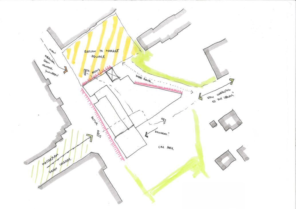
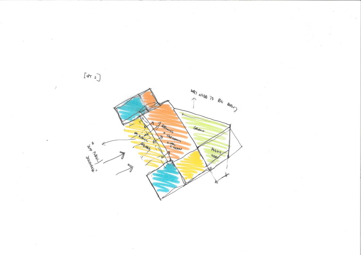
Sketch produced early in the project exploring site opportunities and constraints, fronts and backs etc.
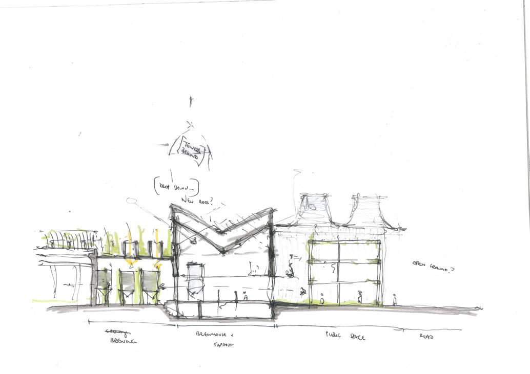
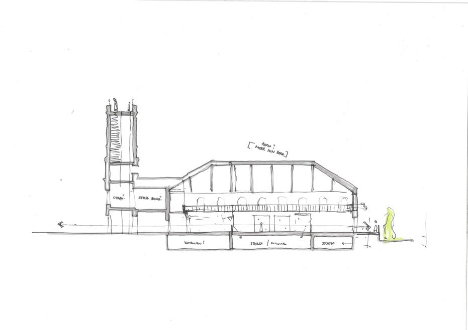
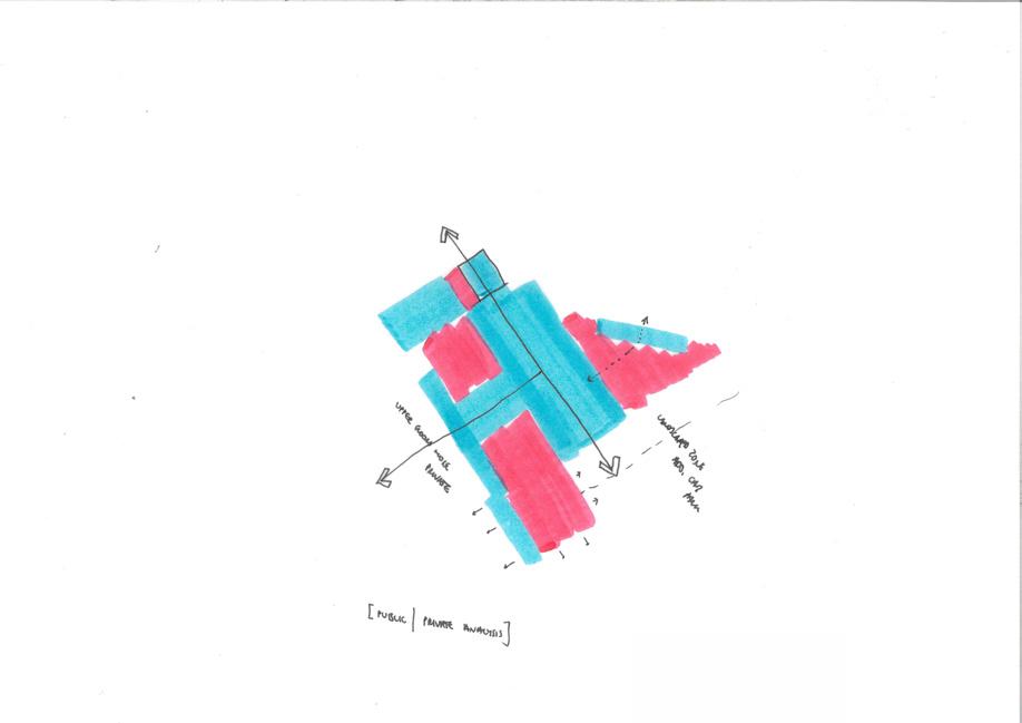
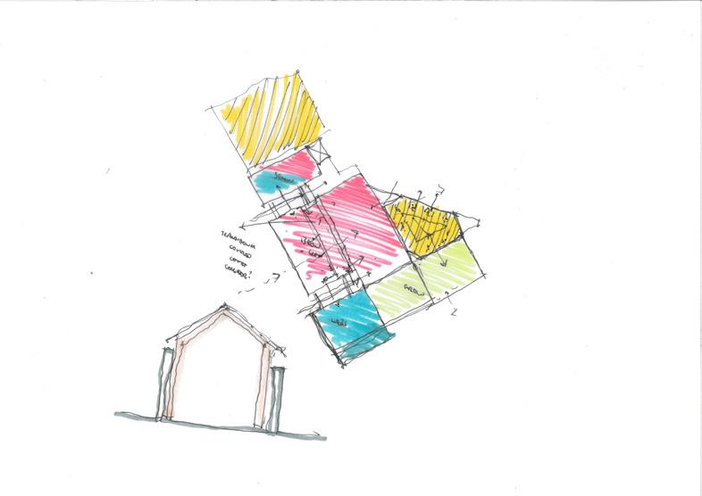
Early stage sketches exploring zoning and adjacencies, testing my initial thoughts in the brief against the constraints of the existing building. This was a big challenge with a solution eluding me for the first 2-3 weeks of the project
My early sections explored a couple of different roof forms for the existing building; either respecting and restoring the old roof form or juxtaposing something new and different in the space. The latter option was eventually chosen as it created a more dramatic space, with the butterfly type roof shown above lending itself to the idea of ‘insertion’ within an existing container
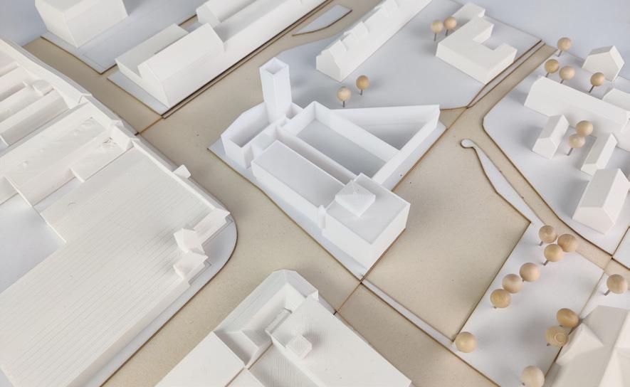
Existing 1:500 site model
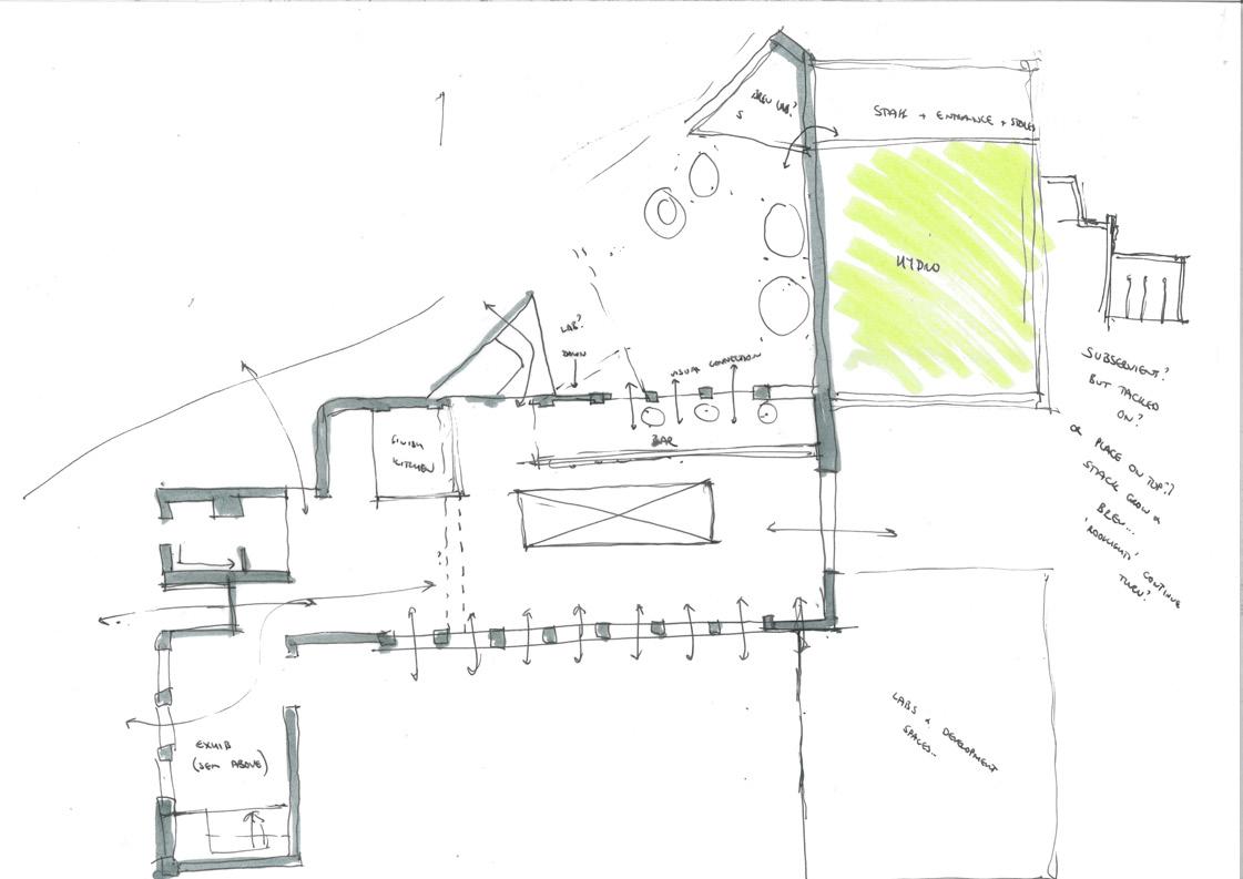
Option 1 floor plan (1:200). This option was successful in activating the existing square to the North with a more logical entrance sequence compared to Option 2, but pulled back too far from the adjacent road with too much of the activity tucked away to the ‘rear’ of the building
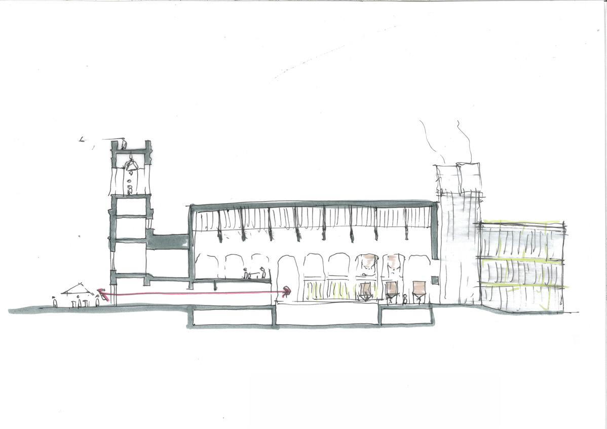
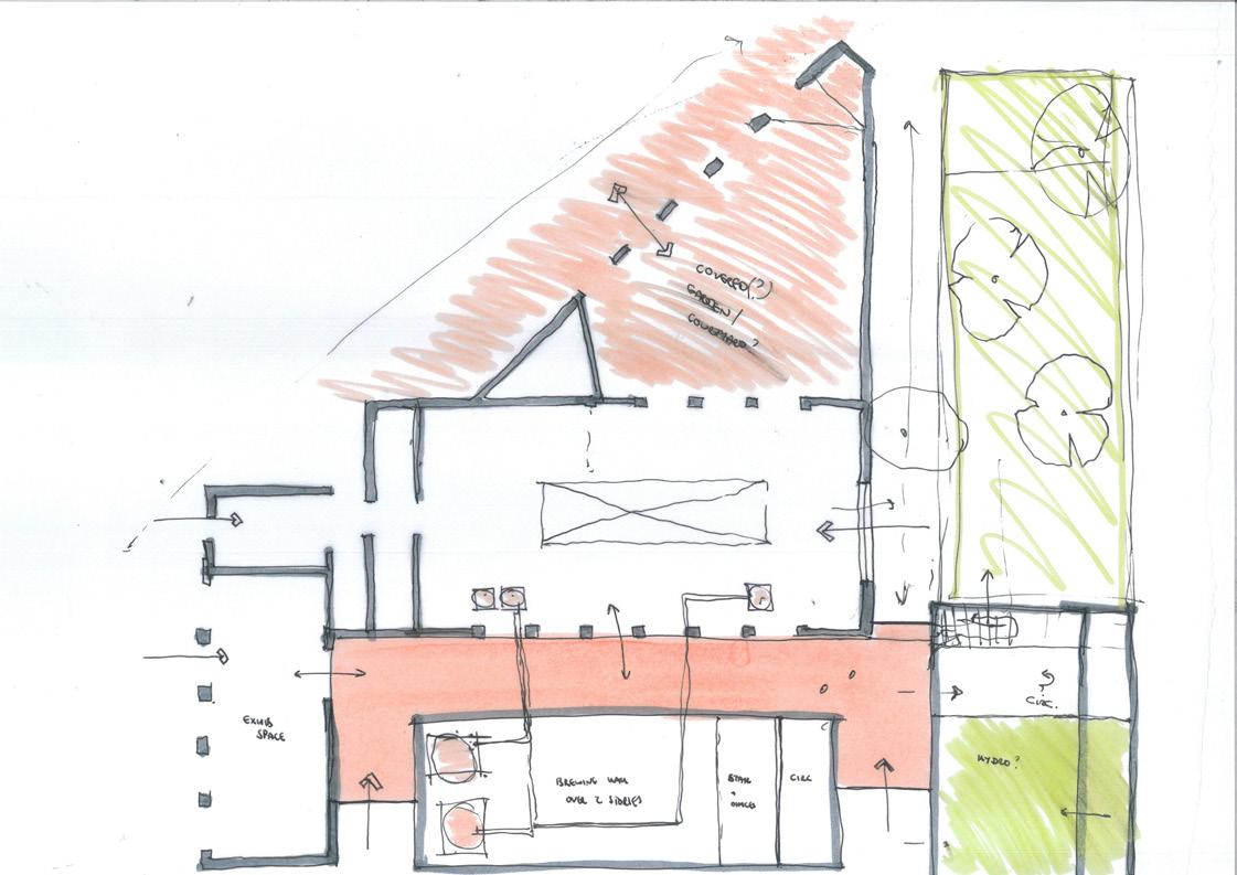
Option 2 floor plan (1:200). Whilst providing a more active frontage to the street and activating Dammas Lane to the East, the entrance sequence was convoluted and didn’t succeed in activating the square to the North. There were also concerns about the extent of reuse of the existing buildings compared with new built footprint
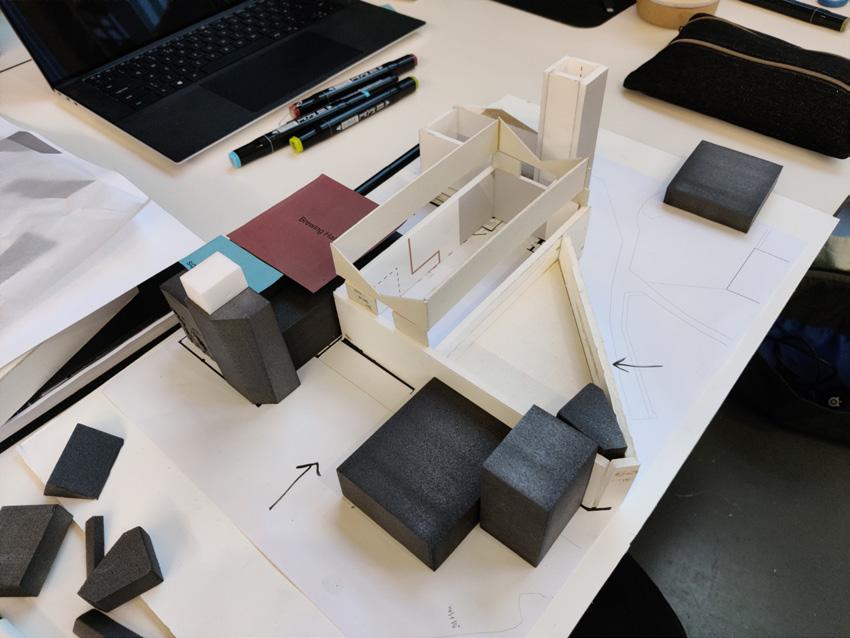
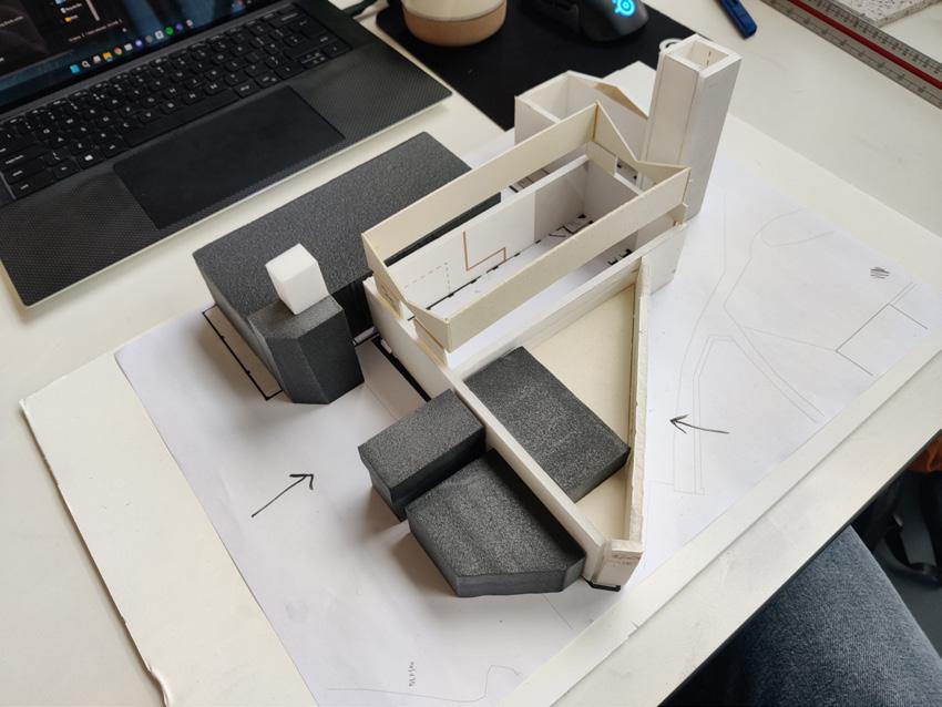
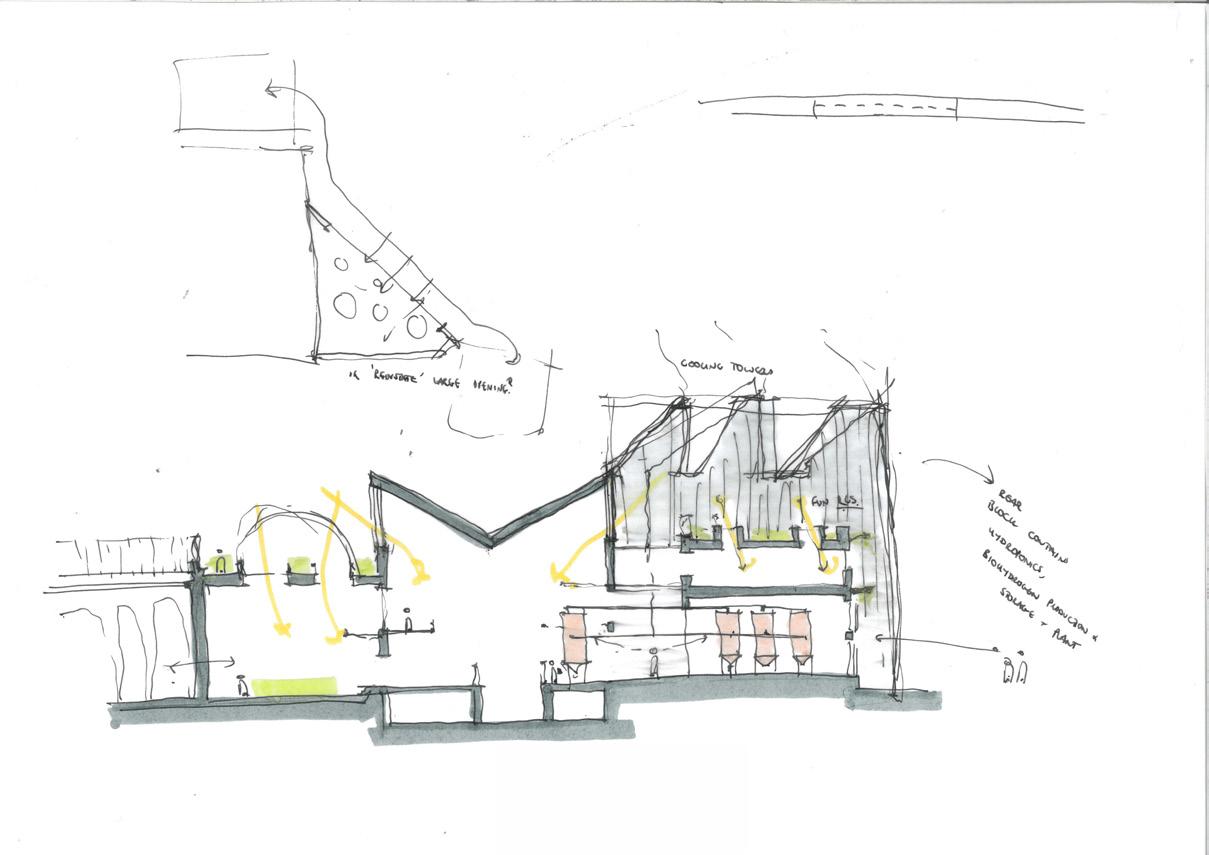
Option 2 sketch section (1:200), exploring the relationships of the various, somewhat sculptural, roof forms with each other

Testing various massing options at 1:200 scale
Up to Interim Review
Block 02 - Weeks 3-5
A New Direction
The desktop review was helpful, but more in the sense of highlighting which directions I shouldn’t be moving forward in, and clarifying the key moves I needed to make.
The inspiration for this new direction came at an unlikely time, whilst swimming one day after uni. Tightening up the massing and wrapping it closer to the existing building created a more coherent proposal, with a logical entrance sequence and a defined ‘back’ for servicing and deliveries.
Balancing Scope and Operational Scale
A crucial challenge at this stage was balancing the overall scale of the building with the requirements of the briefespecially in the hydroponics zone to the South East, which must be a certain size to enable the ‘circularity’ of the process. Various iterations were tested to find a balance between the correct area and correct massing, as I wanted to retain some degree of chamfered edge to reduce its visual weight on ‘The Weavers/The Planks’ lanes to the East.
Unlocking the Tower
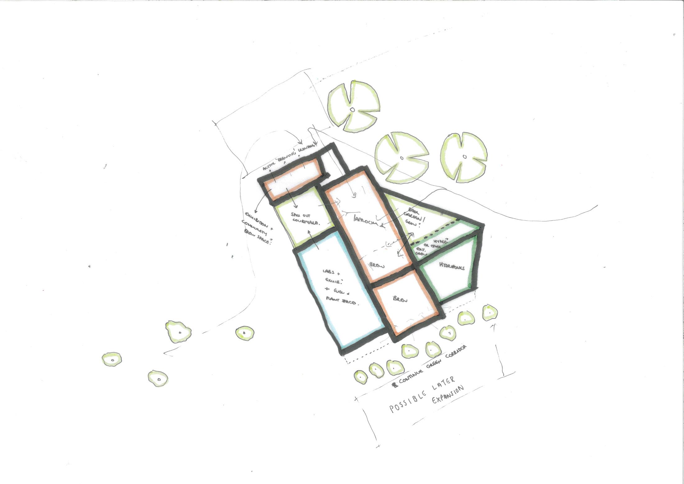
One important move in developing this new iteration was the introduction of a tower element in the South West corner - helping to anchor the two new elevations whilst creating a complex but visually appealing hierarchy between the various new and existing elements.
This tower was fully ‘unlocked’ after our first environmental tutorial, with Andy getting excited about its potential for various environmental functions - air supply, exhaust, water cooling and so on. From the start, this element was made to work hard; solidifying its place in the scheme.
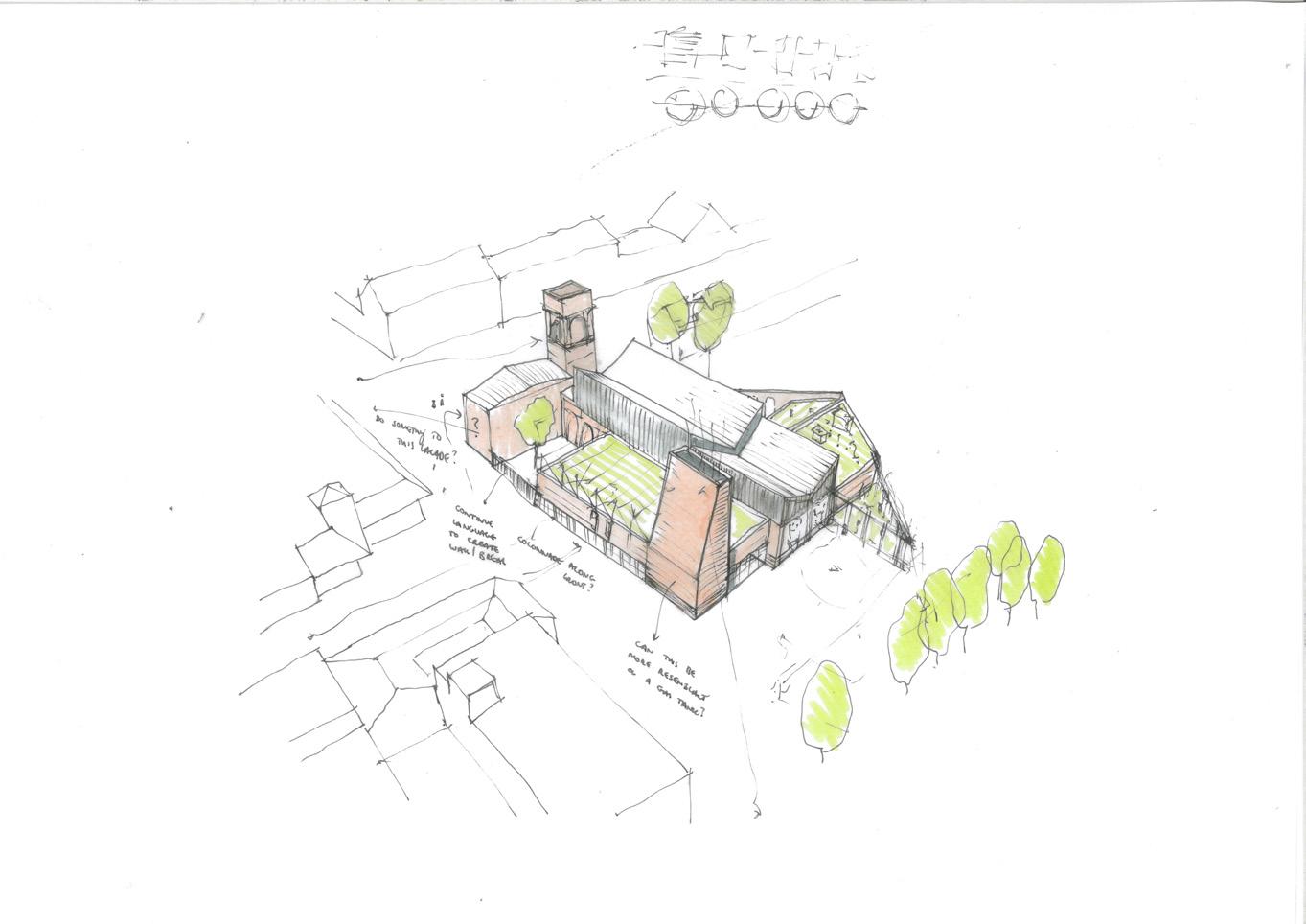
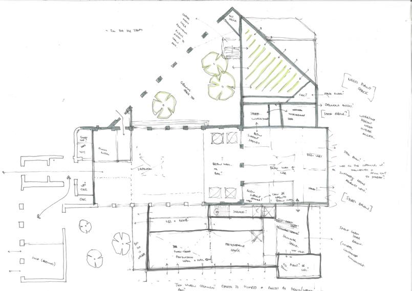
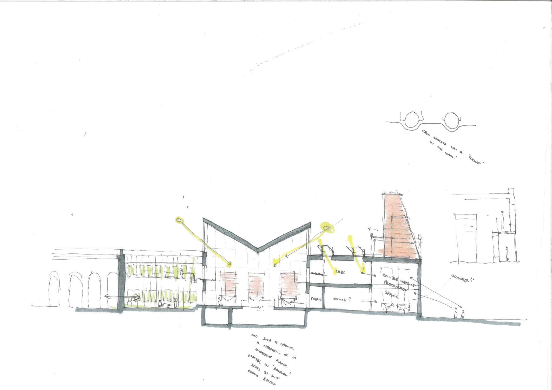
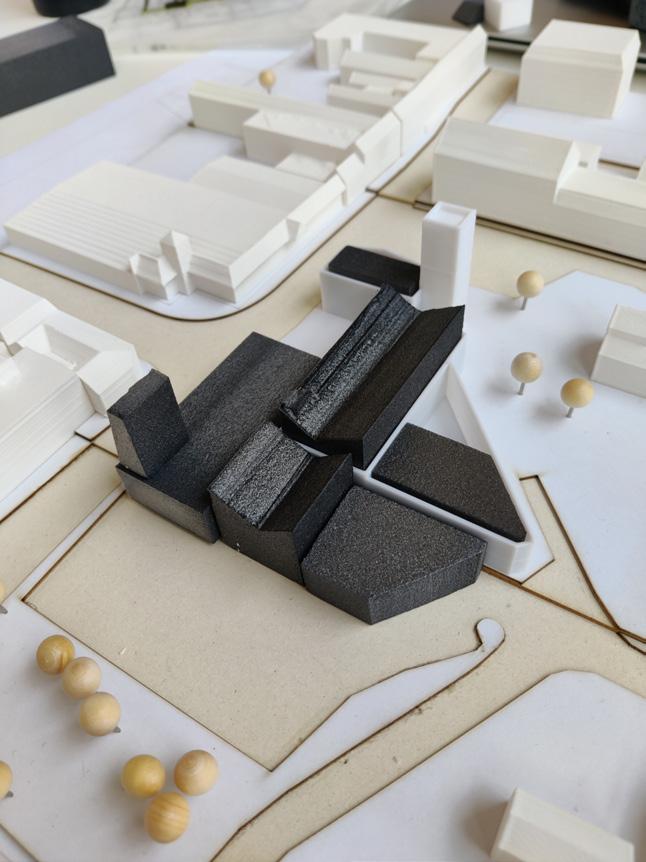
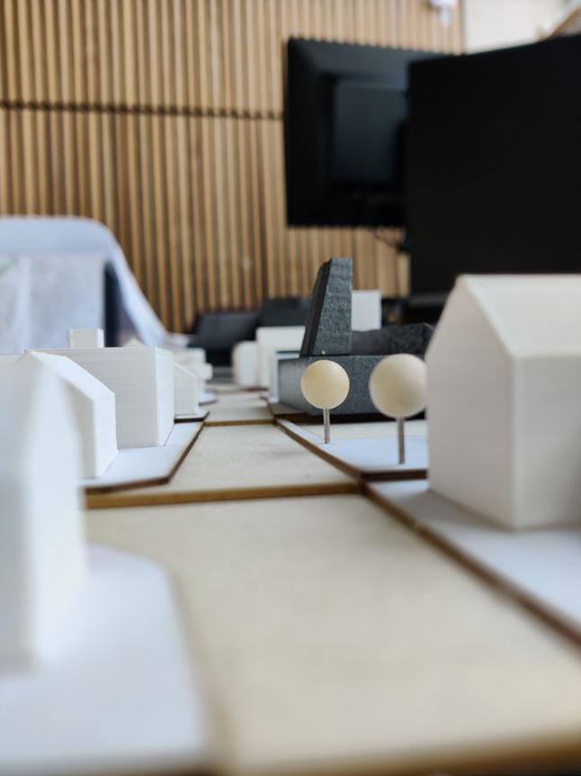
1:500 massing model of the revised proposal, from both high level and eye level. Developing the massing in its context was extremely helpful in testing the relationship of my building with those adjacent, especially to the West and North, as well as ensuring the proposed tower still remained subservient to its existing counterpart
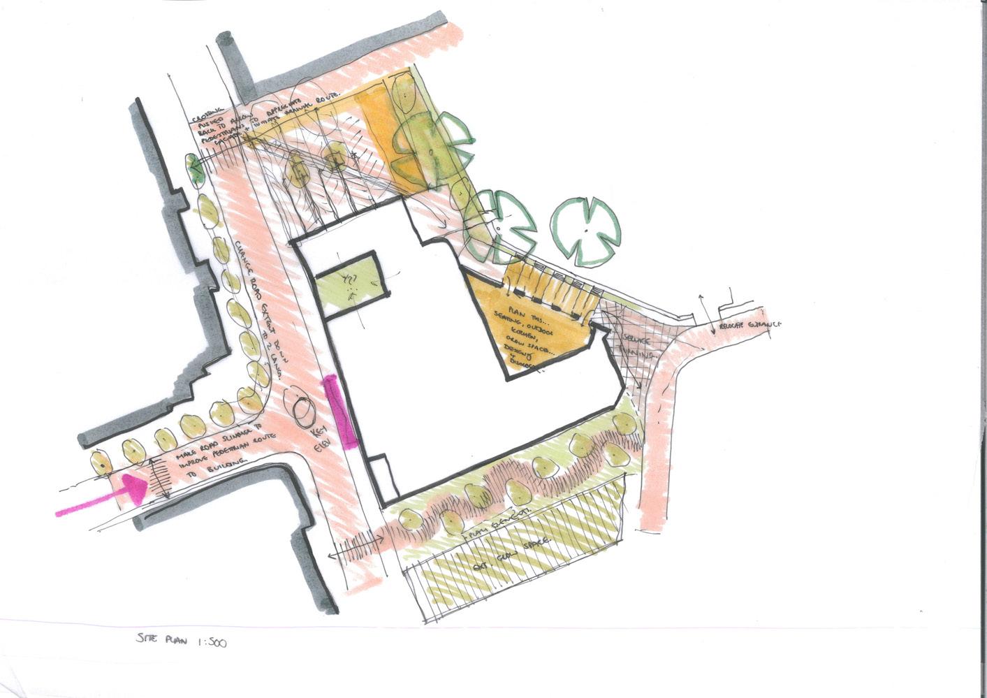
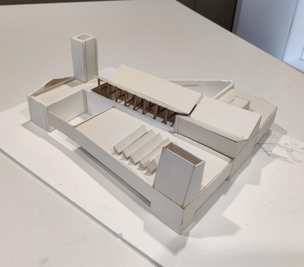

1:200 sketch model. The same model would stay in use through the entire process, allowing me to quickly test various ideas physically and helping discussions at tutorials and reviews
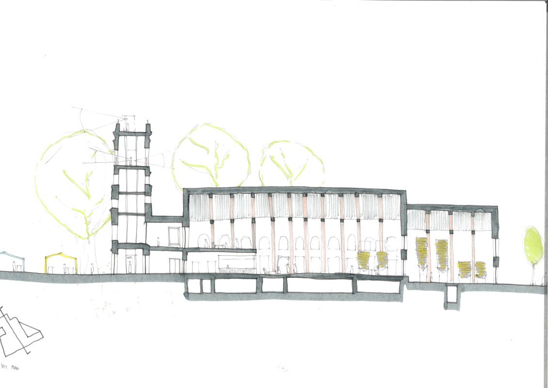
1:200 sketch section exploring the scale of the new roof and taproom below, including the intervention of a mezzanine at first floor. Designing using sections was crucial in ensuring the ‘scale’ of spaces felt correct, both individually and in relation
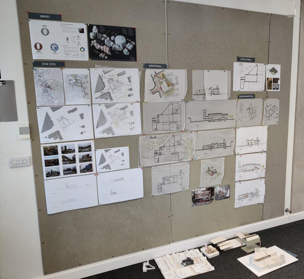
Up to Tectonic Review
Block 03 - Weeks 6-8
Responding to the Road
A main point of discussion following the interim review was that the building did not respond enough to the high levels of activity to the West, and that the plan may be better if the brewing hall (facing South) and power generation space (facing West) were swapped. This turned out to be one of the critical moves of the project; enlivening the elevation and better integrating the building into its context.
There was also a question raised about the location of the tower, and whether it would be better suited in a location closer to the brewing hall in line with its environmental aspirations. This change was considered but ultimately not implemented, as I was worried both about the building becoming too much about one axis (if the tower was centralised), and enjoyed the compositional benefits the tower gave as both an anchor to the new massing, and as an inflection of the existing tower.
Developing a Language of Reuse
During this block, I was encouraged to really push the narrative and language of reuse that was being woven into the project. This exploration came in tandem with developing the tectonic of the project; researching and detailing the reused brick panels, alongside repurposed concrete plank cladding sections.
To aid this, I catalogued the quantities of materials that would be made available post demolition - a somewhat challenging process but one which ultimately helped inform the extent of various materials in the project (such as brickwork and standing seam roof) to ensure these were within the quantities ‘provided’ by the demolished building. It also proved a useful tool in developing the structural language; the initial intention of a recycled concrete frame disregarded in favour of glulam, after calculating that the extent of recycled concrete would only cover the new basement and floor slabs.
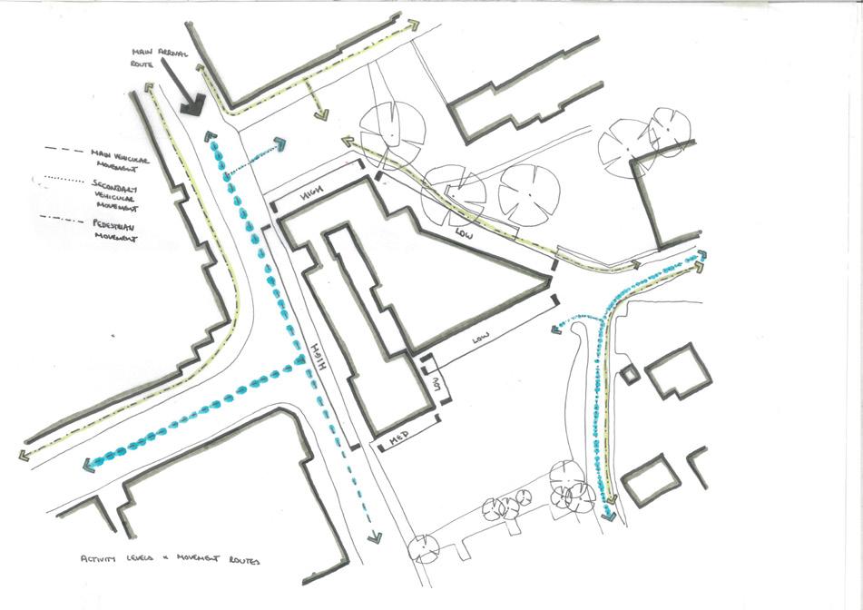
Following the interim review, I produced this quick sketch highlighting routes through and around the site, and the varying levels of activity of each existing facade. This helped to inform my next design moves in restructuring the plan
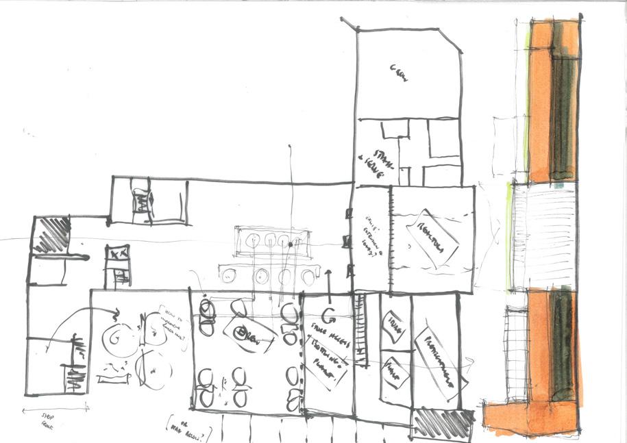
One of the many iterations following the interim review, stripping the scheme back to its core concepts and restructuring based on providing an increased connection to the West street


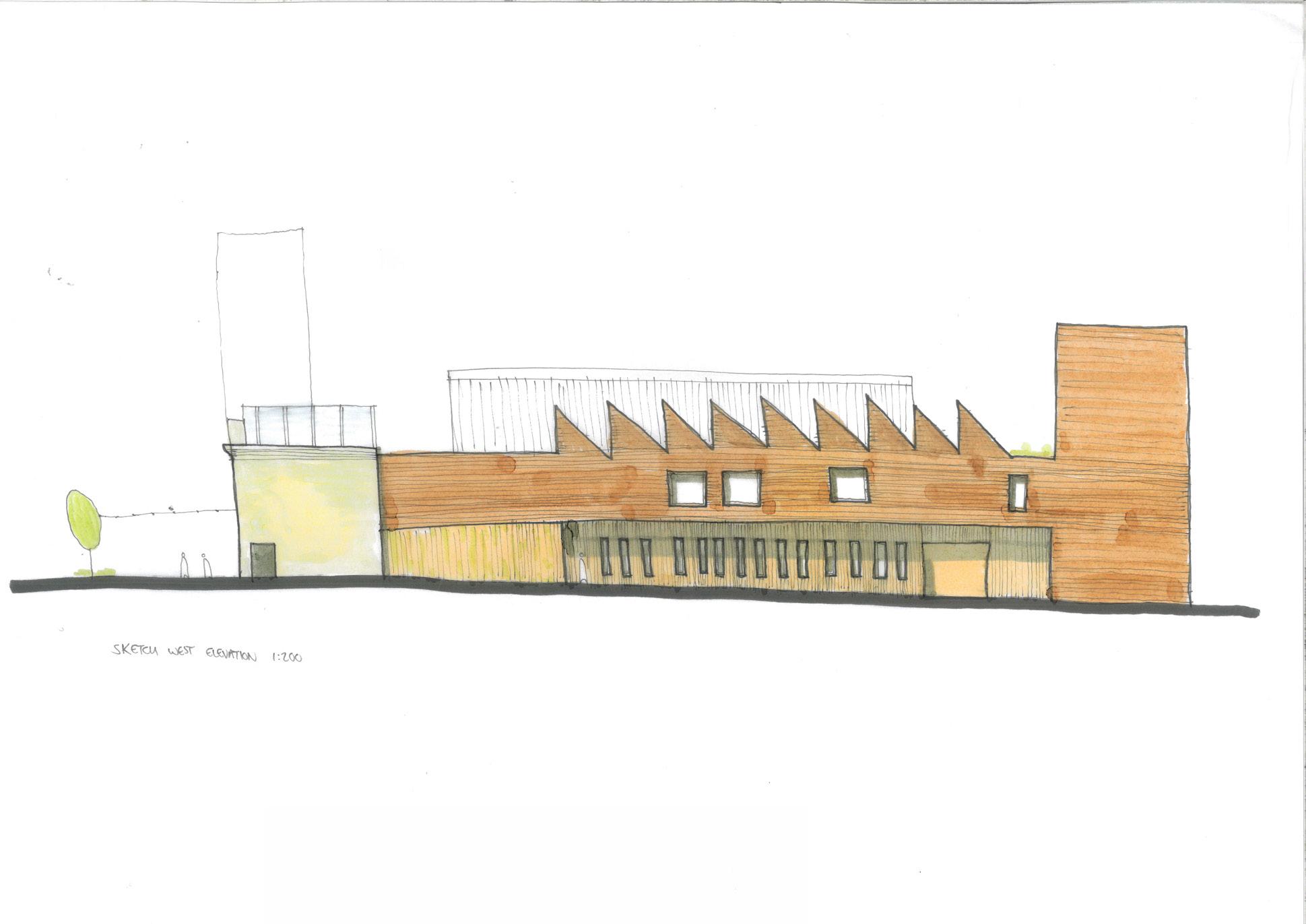
Exploring connections between the taproom, labs and power generation spaces; creating interstitial zones which highlight the junction between new and old
One of the initial versions of the West elevation, which would change a lot through the process as I grappled with both the levels of open/closed, and the connection between the new and old
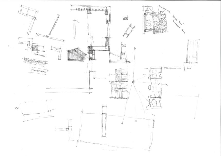
and
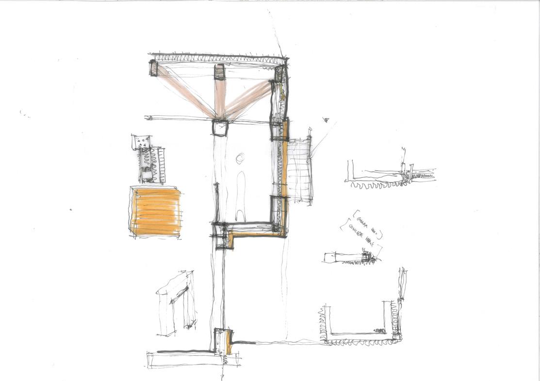
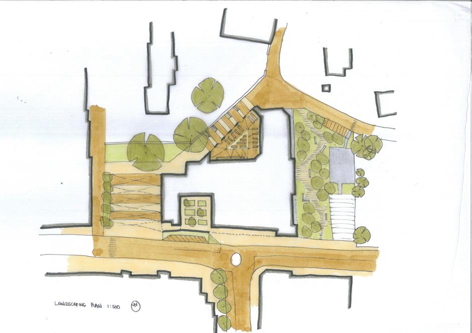
A 1:500 landscape sketch plan produced after the second landscape tutorial, with surface finishes being ‘toothed’ into the language of the existing building helping to meld the two
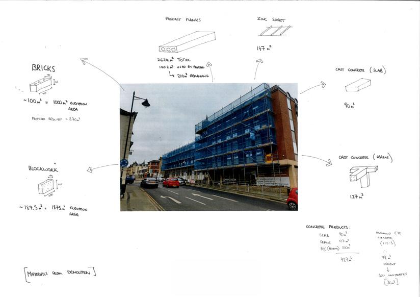
Developing the tectonic of the West facade; a melding of new and old & light and heavy

A 1:200 model of the developed roof truss following our first structural tutorial. Representing the structure in this way physically turned it into a sculptural object which should be (and hopefully was) celebrated in the proposal
A catalogue of salvaged materials gained from the existing demolished building, to aid in decision making about extents of various materials, structural frame choices etc.
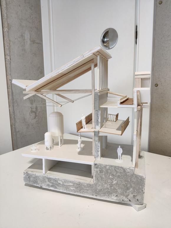
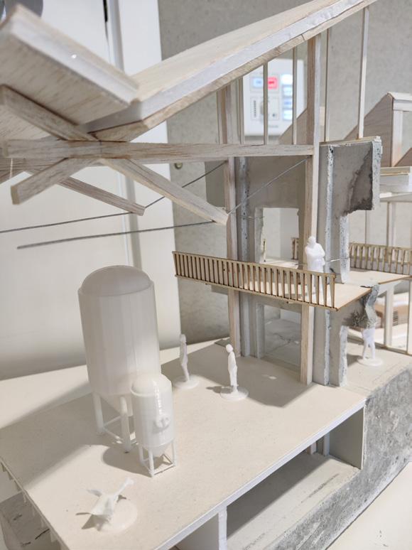
The 1:50 tectonic model produced for the tectonic review. This was the first proper model I had ‘gone to town’ on during my degree (such being the legacy of our first year during COVID lockdown). It was both incredibly rewarding and helpful to make, mashing together several processes from casting to 3D printing. This model forced me to think in depth about the details relating to user experience; the balconies and walkways, connection of the glazing to the roof, and so on, which resulted in a richer and more developed scheme. It also taught me to prop foamboard moulds before you cast, else you end up with a bowed base which needed a solid sanding down in a car park on a Saturday afternoon...
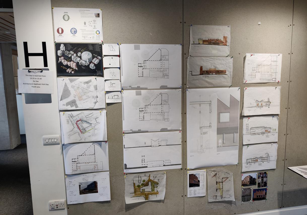
Up to Final Review
Block 04 - Weeks 9-11
Opening Up the Elevation
A key takeaway following the tectonic review was that the West elevation, that facing the road and public realm, had become too closed up. The first step was to rip away the rhythm of thin slot windows and fully open up the elevation at ground level; using the tower at the end to ‘anchor’ the elevation.
Following another comment about leaning in to the industrial, grungy nature of the process within, a galvanised mesh was introduced at the lower level; contrasting the solidity of the brickwork whilst providing shading or controllable privacy to the brewing hall inside.
Servicing (A Happy Accident)
A focus during these last few weeks was tightening up the servicing of the building, checking that everything would work effectively ‘in real life’; staff movement, ductwork routes, deliveries and so on. Being a building built around a process (or several, in this case) it was crucial to the success of the scheme.
This led to the discovery that changes in floor levels clashed with one of my proposed goods lifts. Taking this as an opportunity, I exposed this section of the building to the taproom rather than closing it off as before - in itself a successful move and one in line with my wider conceptual aims of the scheme.
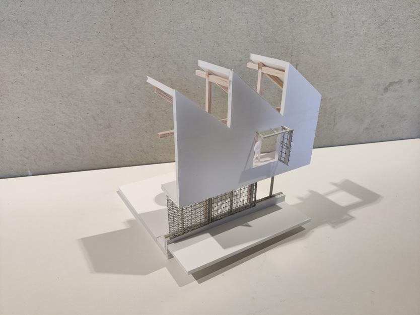
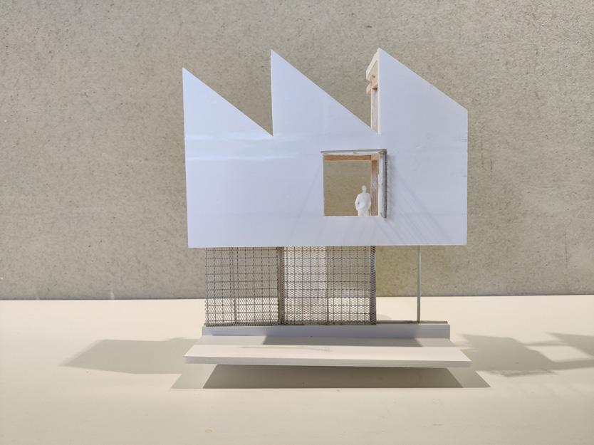
A model produced following the tectonic review reworking the West elevation, pushing the distinction between solid and void with the introduction of mesh screens at street level

Another focus has been on the user experience and feel of the spaces, especially the larger spaces including the taproom. Developing the scheme in a digital 3D model helped greatly here, navigating the model in tutorials to aid conversations. Following our M&M tutorial, I dove into the nuts and bolts of the bar space, both exposing and detailing the various pipes and other greeble that allows this space to function.
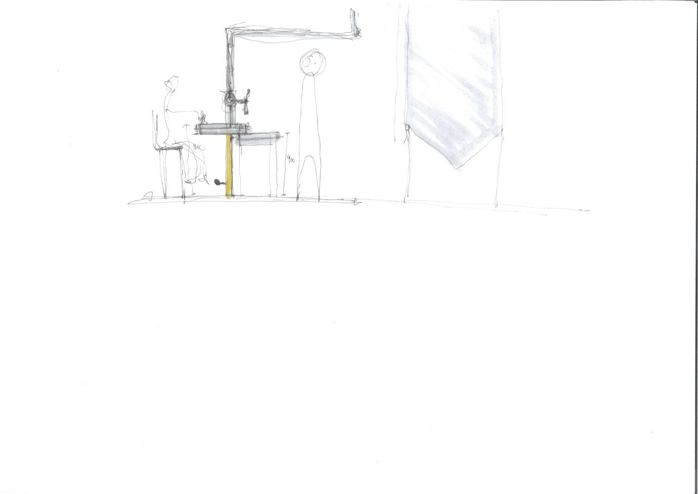
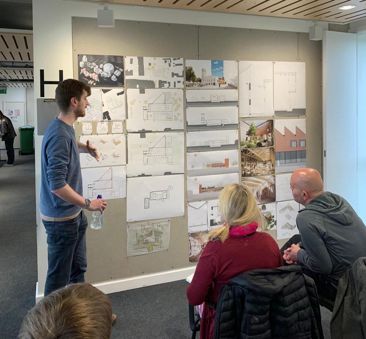
Final Thoughts and Reflections
01:39, 14/05. T Minus 14 hours, 21 minutes. It’s done.
Looking back on the last 13 weeks, it’s ironic that this project has been simultaneously both the easiest and hardest of those I have completed during my time at Bath. Easiest, because I feel like my own personal design language is slowly breaking through, and I have felt much more confidence and conviction in my decisions than previously. And hardest, obviously, as the culmination of my university course; the most complex project I have undertaken, resolved to the greatest level of detail, and with an (in retrospect) absolute pain in the ass of a site. I’ve loved every second, but it’s been one hell of a challenge.
Coming out of the other side, I think I can honestly say I’m happy and proud with the design of this project, and the contents of this report. Of course there are things I wish I could develop further; images I could render or diagrams I could produce. I’d love to be able to sit down for another chat with Andy Jarvis and make sure my calculations for the circularity of this building are actually correct. There’s a certain satisfaction from calculating this yourself, but an even greater one when someone who actually knows what they’re talking about confirms it for you.
The final review gave me a great amount of encouragement in my scheme, but raised a few questions of what could be further developed or resolved. I would have loved to be able to fully design the Eastern courtyard, for example, or the Bio-hydrogen generation space, but time unfortunately did not allow. Further to this, we discussed whether the linking space between the taproom and brewing hall was needed at all - there’s an alternative version of this building where that space is removed, and the connection between the two spaces becomes much more direct. In doing so, maybe you lose the sense of separation between new and old that comes from the thin double height void and structural glass rooflight?
Throughout this project, I’ve really enjoyed the challenges and opportunities that come with working with an existing building. Whilst RIBA Part I requirements (for the extent of new build required in the project to meet the criteria) did steer the initial direction of the project to a certain degree, I feel like this project successfully pushes the remit of adaptive reuse in this context; literally disassembling and breaking down a building into its component parts, to
be reassembled again in a new way. Researching various methods of material reuse, including ‘Resource Rows’ in Copenhagen for which this project references, has fundamentally changed the way I look at buildings, and I hope that more projects like these are constructed in the real world. It’s a paradigm shift that’s really needed across the industry, but one which could be very successful.
As I’ve highlighted through this last section of the report, I’ve really endeavoured to switch up my process for this project and work as much using physical media as possible, rather than resorting to CAD. Looking back, I think these working methods have led to a much richer project, and also left me with a suite of models which I’m really quite happy with. I’m not sure my superglue covered fingers have forgiven me yet, but they’re satisfying artefacts of the journey I’ve gone on over the last few months. My 1:200 model has survived 12 weeks of design iterations, being ripped apart and glued back together almost every week, but was an exceptionally useful tool in discussing the scheme at tutorials and reviews. On reflection, I do wish I’d started to properly migrate to CAD a week or two earlier, just to allow me to better develop my digital 3D model; it would have made the last two weeks much less stressful producing drawings for the final review and the report.
It’s now 02:08, and I should probably get some sleep...
References:
[1]: Oliver, G., No Date. The History of Beer [Online]. Craft Beer & Brewing. Available from: https:// beerandbrewing.com/dictionary/UqfrcsPoAI/#:~:text=As%20best%20we%20are%20able,food%20 %E2%80%A6%20and%20to%20make%20beer [Accessed: 23/01/2024].
[2]: Ibid.
[3]: Ibid.
[4]: Richardson, C., 2023. Is beer healthy? How much should people drink? [Online]. Medical News Today. Available from: https://www.medicalnewstoday.com/articles/is-beer-healthy#summary [Accessed 23/01/2024].
[5]: Mussatto, S.I., Dragone, G., & Roberto, I.C., 2006. Brewers’ spent grain: generation, characteristics and potential applications. Journal of Cereal Science. 43 (2006), pp. 1-14.
[6]: Moirangthem, K., Coda, R., & Rai, D., 2022. Something to cheers to: the value in beer waste [Online]. Teagasc. Available from: https://www.teagasc.ie/news--events/daily/food/something-to-cheers-to-thevalue-in-beer-waste.php [Accessed: 23/01/2024].
[13]: Heumann, A., 2023. Brewery’s Spent Grain : market situation and example of valorisation [Online]. Linkedin. Available from: https://www.linkedin.com/pulse/brewerys-spent-grain-market-situationexample-valorisation/ [Accessed: 23/01/2024].
[8]: Martin, D.S., 2021. New Strategies for Improving the Sustainability of Breweries: Full Waste Recovery for Aquaculture Feed [Online]. European Commission. Available from: https://webgate.ec.europa.eu/ life/publicWebsite/project/LIFE16-ENV-ES-000160/new-strategies-for-improving-the-sustainability-ofbreweries-full-waste-recovery-for-aquaculture-feed#:~:text=The%20largest%20waste%20by%20volume,the%20remaining%2020%25%20is%20landfilled [Accessed: 23/01/2024].
[9]: Conway, J., 2023. Number of breweries in the United Kingdom (UK) from 2018 to 2022 [Online]. Statistica. Available from: https://www.statista.com/statistics/1121271/number-of-breweries-in-the-unitedkingdom/#:~:text=Over%20the%20period%20in%20consideration,2018%20to%202%2C426%20in%20 2022 [Accessed: 23/01/2024].
[10]: Verstl, I., 2023. UK beer report 2022: the numbers [Online]. Brauwelt. Available from: https://brauwelt. com/en/international-report/europe-russia/646449-uk-beer-report-2022-the-numbers#:~:text=UK%20 beer%20production%20dropped%202.3,excluded%2C%20production%20rose%204.3%20percent [Accessed: 23/01/2024].
[11]: Panjicko, M., et al., 2017. Biogas production from brewery spent grain as a mono-substrate in a twostage process composed of solid-state anaerobic digestion and granular biomass reactors. Journal of Cleaner Production, 166(2017), pp.519-529.
[12]: Untappd, No Date. Brewing Unplugged [Online] Available from: https://untappd.com/ BrewingUnplugged [Accessed: 23/01/2024].
[13]: Rothamstead Research, 2023. Rothamstead Research [Online]. Rothamstead. Available from: https:// www.rothamsted.ac.uk/ [Accessed: 23/01/2024].
[14]: Ekonoke, 2024. How can we guarantee climate-resilient hops? [Online]. Ekonoke. Available from: https://www.ekonoke.com/how/ [Accessed: 23/01/2024].
[15]: Validate, No Date. Biotechnology and Biological Sciences Research Council [Online] Validate Network. Available from: https://validate-network.org/biotechnology-and-biological-sciences-research-council [Accessed: 23/01/2024].
[16]: Swindon Council logo (from respective organisation).
[17]: LETI, 2020. Climate Emergency Design Guide [Online]. Available from: https://www.leti.uk/cedg [Accessed: 23/01/2024].
[18]: Historic England, 1986. CORN EXCHANGE AND TOWN HALL [Online]. Available from: https:// historicengland.org.uk/listing/the-list/list-entry/1023523?section=official-list-entry [Accessed: 23/01/2024].
[19]: Total Swindon, No Date. History of Old Town [Online]. Available from: https://www.totalswindon. com/community/history-of-old-town-swindon/#:~:text=The%20Locarno%20was%20commissioned%20 in,%2C%20balls%2C%20lectures%20and%20readings. [Accessed: 23/01/2024].
[20]: Ibid.
[21]: Atkinson, A., 2022. 21. The Corn Exchange Old Town [Online] Born Again Swindonian. Available from: https://swindonian.me/2022/08/26/the-corn-exchange-old-town/ [Accessed: 23/01/2024].
[22]: Ibid.
[23]: Shoesmith, K., 2005. New hope for Locarno [Online]. Swindon Advertiser. Available from: https://www. swindonadvertiser.co.uk/news/665745.new-hope-for-locarno/ [Accessed: 23/01/2024].
[24]: SwindonWeb, No Date. The Age of the Tram [Online]. Available from: https://www.swindonweb.com/ index.asp?m=8&s=116&ss=345&t=THE+AGE+OF+THE+TRAM [Accessed: 23/01/2024].
[25]: Sendra, P., & Sennett, R., 2020. Designing for Disorder. London: Verso.
[26]: Woodland Trust, No Date. PHYTOPHTHORA RAMORUM [Online]. Available from: https://www. woodlandtrust.org.uk/trees-woods-and-wildlife/tree-pests-and-diseases/key-tree-pests-and-diseases/ phytophthora-ramorum/#:~:text=Phytophthora%20ramorum%20is%20a%20fungal,of%20felling%20 around%20the%20UK. [Accessed: 14/05/2024].
[27]: Freement, 2024. Smart Liberator [Online]. Available from: https://freement.nl/smart-liberator/ [Accessed: 14/05/2024].
[28]: LETI, 2020. Climate Emergency Design Guide [Online]. Available from: https://www.leti.uk/cedg [Accessed: 14/05/2024].
[29]: Arnold, W., Gibbons, O., & Orr, J., 2020. A brief guide to calculating embodied carbon [Online]. IStructE. Available from: https://www.istructe.org/IStructE/media/Public/TSE-Archive/2020/A-brief-guideto-calculating-embodied-carbon.pdf [Accessed: 14/05/2024].
[30]: Ove Arup & Partners Ltd, 2023. Embodied Carbon: Timber [Online]. Available from: https://www. istructe.org/IStructE/media/Public/Resources/ARUP-Embodied-carbon-timber-v2.pdf [Accessed: 14/05/2024].
[31]: Hemspan, 2024. Hemspan Biowall [Online]. Available from: https://hemspan.com/product/bio-wallnatural-fibre-hemp-insulation/ [Accessed: 14/05/2024].
[32]: HM Government, 2023. Approved Document L [Online]. Available from: https://www.gov. uk/government/publications/conservation-of-fuel-and-power-approved-document-l [Accessed: 14/05/2024].
[33]: Brewers Association, No Date. Energy Usage, GHG Reduction, Effi ciency and Load Management Manual [Online]. Available from: https://www.brewersassociation.org/attachments/0001/1532/energy_ lighting.pdf [Accessed: 14/05/2024].
[34]: Resonics, 2020. Demystifying Acoustics – The Resonics Guide to Reverberation Time [Online]. Available from: https://resonics.co.uk/resonics-guide-reverberation-time/ [Accessed: 14/05/2024].
[35]: Mike Wye, No Date. Savolit Plus Wood Wool Board [Online]. Available from: https://www.mikewye. co.uk/product/savolit-plus-wood-wool-board/ [Accessed: 14/05/2024].
[36]: JCW Acoustic Supplies, No Date. Absorption coefficients of common building materials and finishes [Online]. Available from: https://www.acoustic-supplies.com/absorption-coefficient-chart/ [Accessed: 14/05/2024].
[37]: Centec, No Date. DeGaS-Hot [Online]. Available from: https://www.centec.de/process-systems/powerplants/degas-hot/#:~:text=Description,the%20top%20of%20the%20column [Accessed: 14/05/2024].
Images and Figures:
[1]: Authors Own, with information from: Carling, 2020. Who Owns What In The UK Brewing Scene? [Online]. Carling Partnership. Available from: https://www.carlingpartnership.com/insights/who-owns-what-in-theuk-brewing-scene/ [Accessed: 23/01/2024].
[2]: Morley, K., 2024. National Grid: Live [Online]. Available from: https://grid.iamkate.com/ [Accessed: 23/01/2024].
[3]: Berndtston, H., 2023. ÅBEN Brewery / Pihlmann Architects [Online]. Archdaily. Available from: https://www.archdaily.com/1005549/aben-brewery-pihlmann-architects?ad_medium=gallery [Accessed: 14/05/2024].
[4]: Elwood, B., 2020. CORN EXCHANGE AND TOWN HALL [Online]. Historic England. Available from: https://historicengland.org.uk/listing/the-list/list-entry/1023523?section=comments-and-photos [Accessed: 23/01/2024].
[5]: Local Studies Swindon Libraries, 2018. 1859: Old Swindon Town Hall in Market Square [Online]. Flikr. Available from: https://www.flickr.com/photos/swindonlocal/45434236014 [Accessed: 23/01/2024].
[6]: Wilson & Willcox, 1866. Design for the Corn Exchange and markets (adjoining the Town Hall), Swindon, Wiltshire: sections through the tower and butter market. [Drawing]. At: V&A, RIBA Drawing Archive, Ref: PB511/6(1).
[7]: Brisland, M., 2023. Memories of Southampton’s old ice rink [Online]. Southern Daily Echo. Available from: https://www.dailyecho.co.uk/news/23322192.memories-southamptons-old-ice-rink/ [Accessed: 23/01/2024].
[8]: Historic Mapping Data from Digimaps.
[9]: Kelsey, T., 2016. Barry Leighton takes a walk with man who has £35m vision for Swindon landmark [Online]. Swindon Advertiser. Available from: https://www.swindonadvertiser.co.uk/news/14755322.barryleighton-takes-a-walk-with-man-who-has-35m-vision-for-swindon-landmark/ [Accessed: 23/01/2024].
[10]: BBC Wiltshire, No Date. Historic Swindon Photos 2 [Online]. BBC. Available from: https://www.bbc.co.uk/ wiltshire/content/image_galleries/historic_swindon_photos_gallery2.shtml?6 [Accessed: 23/01/2024].
[11]: Michaud, F., 2019. Avling Kitchen & Brewery / LAMAS [Online]. Archdaily. Available from: https://www. archdaily.com/926496/avling-kitchen-and-brewery-lamas?ad_source=search&ad_medium=projects_tab [Accessed: 23/01/2024].
[12]: Fischer, O., 2019. Resource Rows [Online]. NREP. Available from: https://nrep.com/project/resourcerows/ [Accessed: 14/05/2024].
