Hop[e] Brewing
Year 4.2 - Final Year Project
Location: Swindon, UK
Sector: F&B / Research
Year: 2023 / 2024
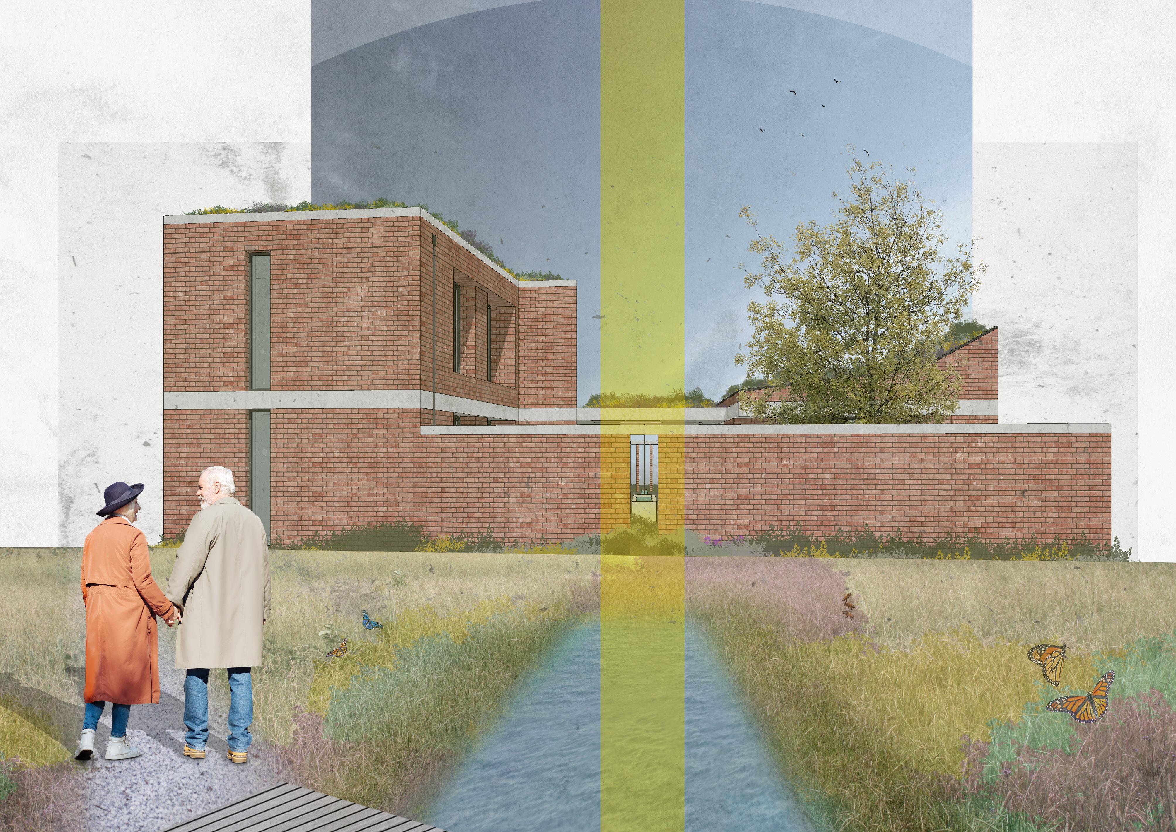
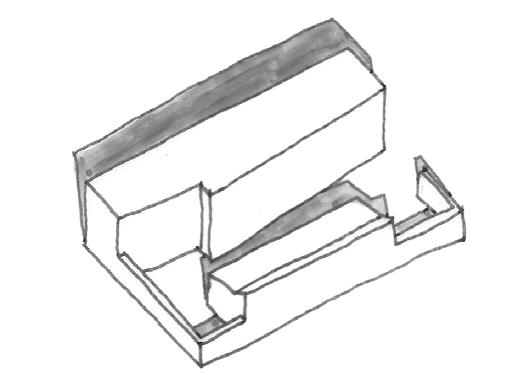
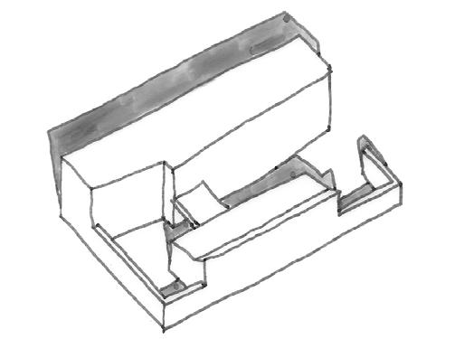
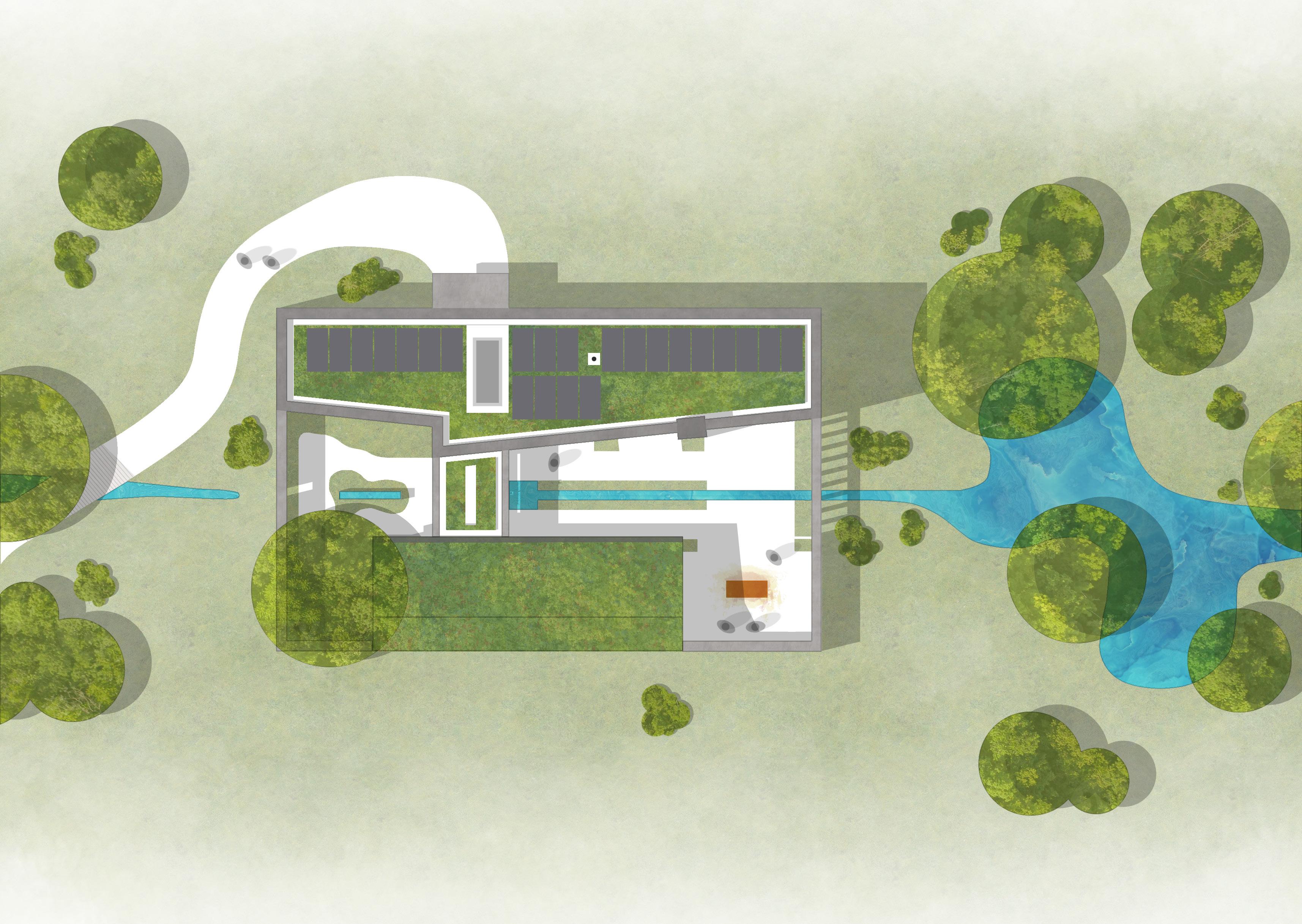
The culminating design project of my undergraduate degree is a cyclical brewery; merging the historic and traditional process of brewing with cutting edge science to create a process where ingredients are cultivated in-house and waste products are recycled into biogas. The proposal reimagines the vacant Old Town Hall & Corn Exchange in Swindon as a test bed for this new method of brewing; a manifesto project to develop and expose this technology for adoption by larger brewing manufacturers. Taking references from the existing Listed structure and arranged as an inflection of served and service zones, the proposal offers opportunities for the public to observe and understand the roles the various spaces and processes play in the continued operation of the building.
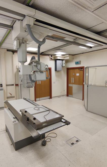
With the demolition of an existing neighbouring building a necessity for the proposal, the project takes a unique approach to repurposing these otherwise waste materials. Instead, they are viewed as a kit of parts, with their integration into the scheme creating a visible dialogue of reuse.
The full design report for this project can be viewed by scanning the QR code above, or by clicking here

p. 7


Pre-TreatmentChemicalsIn C0 2 fromfermentation Hops Barley BREWEDPRODUCTS OUT Yeast Treated&filtered wastewater recirculated‘Excess’wasteheatnot distributedintobrewingtanks toUFHsystem mashUnreactedgrain recirculated KITCHEN Grainmash composted WASTEIN 01 02 03 04 05 06 07 08 SpentGrains 09 10 11 12 13 13 13 14 14 15 16 17 18
In 2020, global annual beer production was estimated at 1.82 billion hL (1hL=100L). Of all waste produced during this process, wet BSG (Brewers Spent Grain) accounts for 85% - equating to an annual production of 39 million tons worldwide. For every 100 litres of beer produced, 20kg of spent grains are created as a waste product.These currently have little opportunity for further use outside of feedstocks or compost, with around 20% sent to landfill. For every ton of BSG sent to landfill, 513kg CO2 is released.
In 2022, the UK produced 37.5 million hL of beer, ranked 4th in the EU. Using the ratios discussed previously, it can be estimated that the approximate annual UK production of brewers spent grains is 750,000 tons. Anaerobic digestion processes can turn these grains into hydrogen; a clean fuel which can be turned into electricity using a fuel cell. The only waste emission is water; the ‘left over’ BSG can be used for compost. A circular model is critical to generate maximum potential from this otherwise waste product - the UK produces enough spent grains to generate enough clean energy to satisfy the annual power demand of 1.1 million homes.


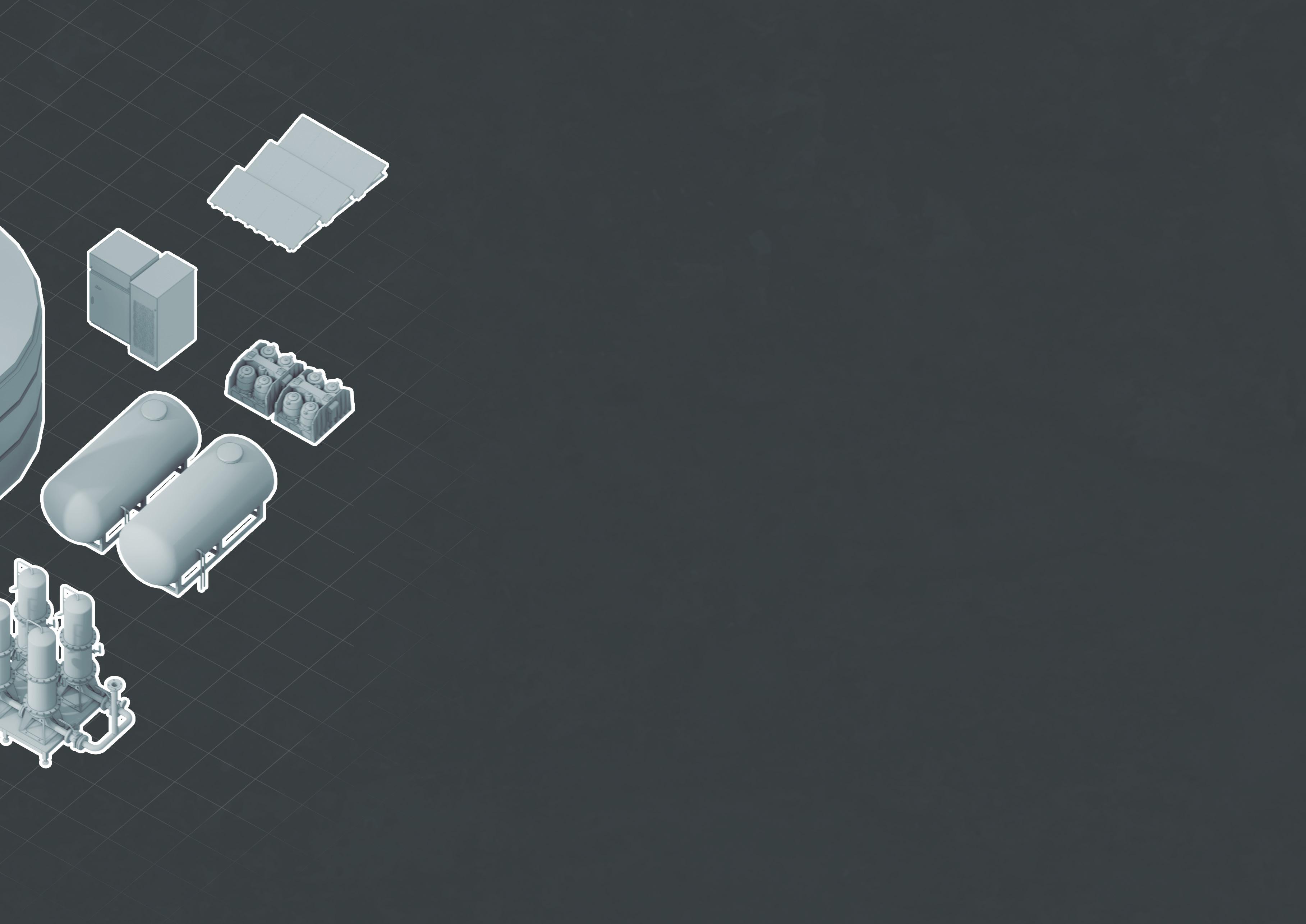
Lauter Tun
Brewing Kettle
Whirlpool Tank
Fermentation Tank
Serving Tanks, Canning & Kegs
Pre-treatment Tank
Separator Tanks
Granular Biomass Reactor
Anaerobic Digester
Exhaust Gas Flue
Hydrogen Storage Tanks
Hydrogen Fuel Cells
Water Filtration System
Solar PV Battery Storage
1 Ton BSG Waste Power OR 513kg CO2 3900 kWh
Beer movement Linework Key: Water movement Plant movement Waste movement Chemical movement 01 Process Key: 02 03 04 05 06 07 08 09 10 11 12 13 14 15 16 17 18 19 20 21 22 23 RWH Tank UV Treatment Water Storage Tank Vertical Hop Farm External Growing Areas
Macerator
Composting
Grain Mill
POWER POWER 19 19 21 20 22 23
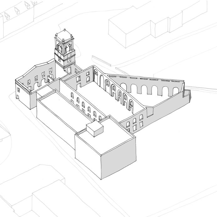


The existing 1970’s office block (‘The Forum’) is demolished. Materials salvaged and retained to be reused within the new proposal.
New trussed butterfly roof structure and mezzanine inserted into existing Corn Exchange. Continuous clerestory added to East and West elevations between the underside of the new roof, and top of existing wall.
New massing proposed to South and West of existing building, with the extent of massing to the South informed by historic plot boundaries. Massing stopped short of the existing Town Hall to form a courtyard and allow the existing building to breathe.
p. 10
[Demolish]
[Insert]
[Envelop]
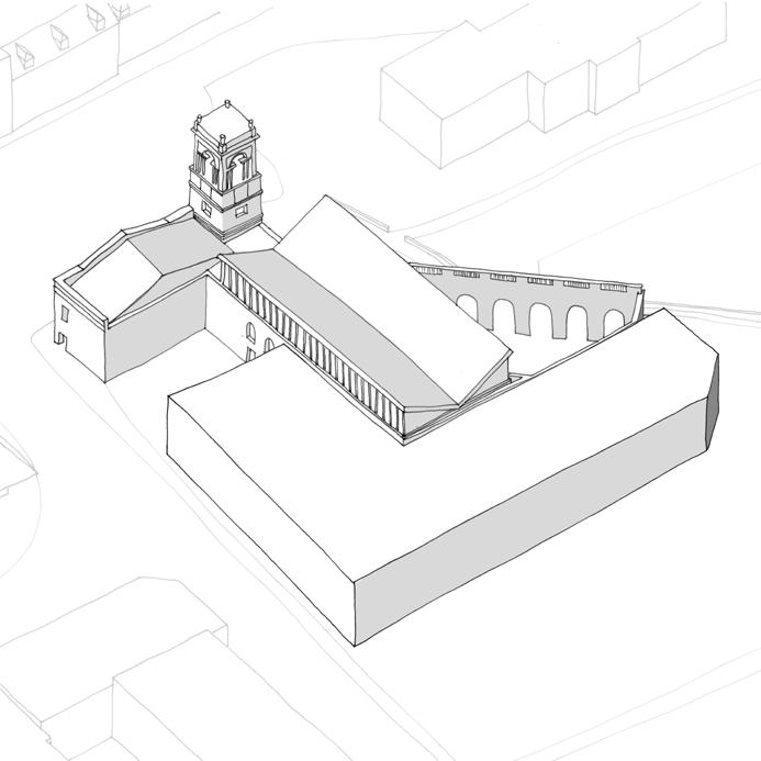

[Align] [Inflect]
The elevation to the West is skewed to align with adjacent road edge, maximising the active frontage and meshing the building with the public realm.
New tower added to South West corner to anchor the new massing, acting as an inflection of the existing bell tower to the North. The new West facade at first floor level is extruded to abut the existing Town Hall building, providing enclosure to the new courtyard.
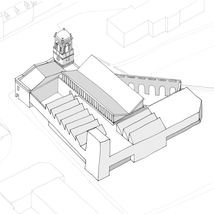
[Emphasise]
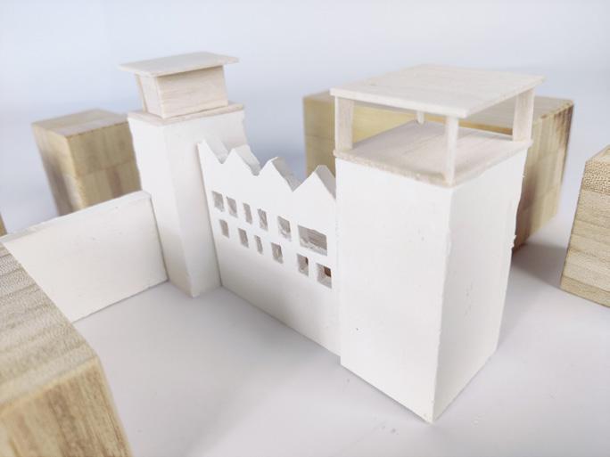
Sections of the Ground Floor are recessed to add vertical emphasis to the new elevations and further reinforce the solidity of the new tower. Sawtooth roof planes are added over key spaces (the brewing hall and labs) to provide North light and break up the flat roof plane.
p. 11


My proposal aims to re-inhabit the existing vacant Old Town Hall and Corn Exchange, known locally as the Locarno. The building has a rich history - built in 1852 and currently Grade II listed. It was gutted by two fires in 2002 and 2004 which left the building as a vacant shell; long since abandoned with no plans for its redevelopment.
Being a highly active, public building, the project aims to enliven the area surrounding the Old Town Hall and so breathe life into this fractured area of Swindon. The building can be seen as a nexus; stitching together the myriad of architectural languages, urban grains and masterplanning typologies which clash within the wider context of Old Town. It also creates a building which the community can rally around, and from which they can draw new civic pride.
My proposal sees an adjacent 1970’s office block demolished; the structure used as a ‘catalogue of parts’ which both informs the design of, and is used in, the new building. Through the development of the project, a language of reuse has emerged, with materials used in their raw and unapologetic state as taken from the demolished building. New interventions are designed in a lighter, sympathetic language, sparking a dialogue between new and old.
 Visual from Taproom
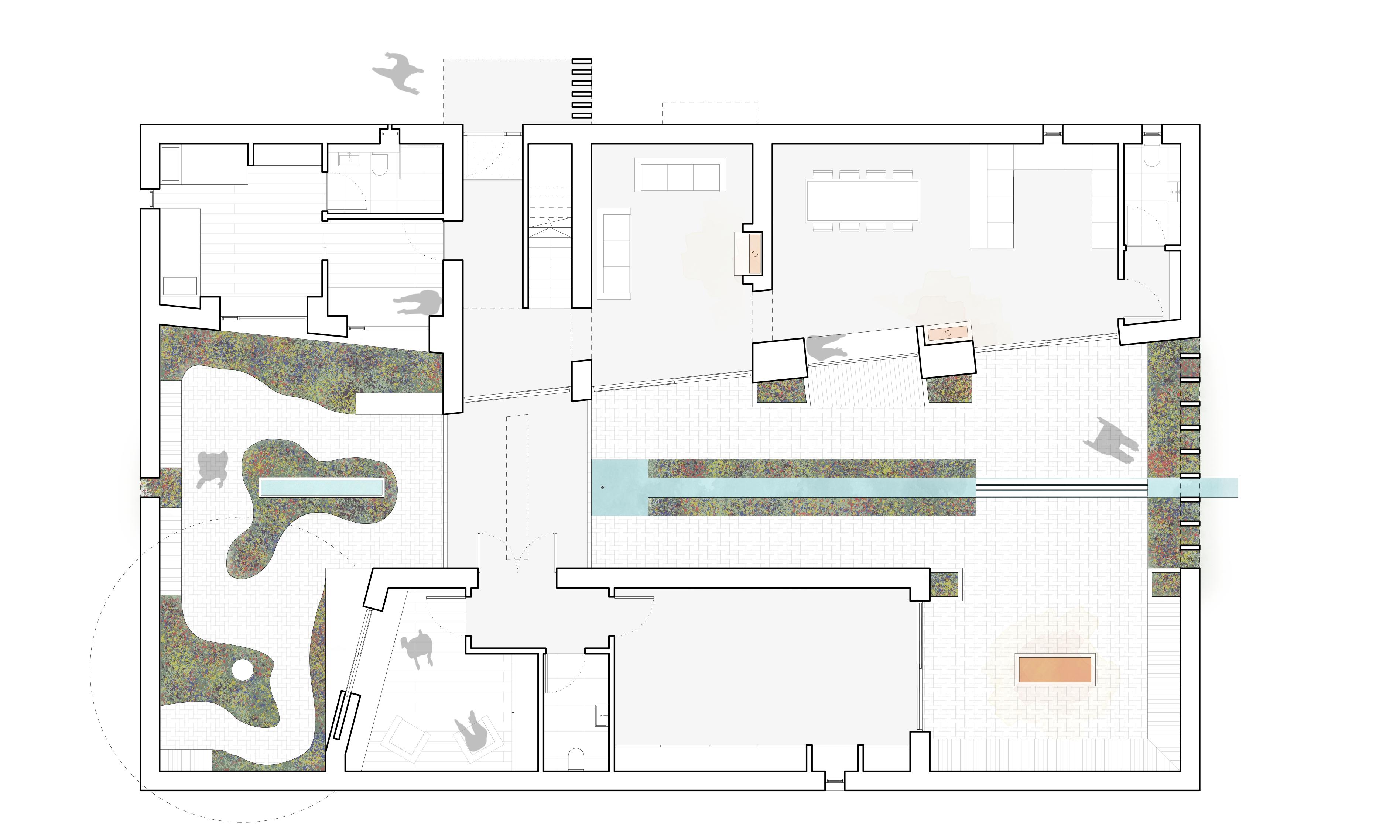
The proposal is planned around an inflection of public and manufacturing zones, reflecting the historic and new elements of the scheme. Interfaces at the boundaries provide opportunities for the public to observe and understand the roles the various spaces play in the continued operation of the building.
The building is a permeable entity, able to be entered and explored from several angles. This naturally draws the users into the heart of the proposal; the taproom. From here, each distinct aspect of the building is visible, and the served/service boundaries typical to food & drinking establishments are blurred.
p. 15 Ground Floor Plan
01 01 02 02 03 03 04 04 05 05 08 08 08 07 07 06 06 09 09 12 10 10 11 11 12 13 13 14 14 15 15 16 16 Taproom & Bar Exhibition Space Entrance Tower Prep Kitchen Beer Garden Shop Hydroponics Growing Hall Observation Space Brewing Hall Packaging & Storage Workshop Bio-hydrogen Generation Bio-hydrogen Storage Goods Lift Seminar Room Changing Places W.C
p. 16 VENTED AT TOP AND BOTTOM? C B A D E Tectonic Section 20m 10 20m 15
The scheme proposes a clear tectonic strategy to clearly differentiate historic, reclaimed and proposed elements. New structure is typically lightweight timber, contrasting with the heavier masonry of the existing building. This creates a strong narrative of levels of permanence - the new lightweight structure easily removable at the end of its life, whereas heavier elements (including those reclaimed) are tied to the site either in their historic form or reimagined for a new lease of life.
The proposal endeavours not to purely reuse materials in their original forms, but to reimagine how they may be reused or repurposed into forms not originally intended. This both extends the life of materials which would otherwise be left as waste, and opens a crucial dialogue on how new projects elsewhere in Swindon, the UK or across the world can inventively reuse old or reclaimed materials.
Within the existing Corn Exchange which houses the proposed taproom, the main intervention takes the form of a glulam butterfly truss, a lightweight structure which supports the roof above whilst allowing for generous clerestory above the existing walls. These elements come together to create a language of insertion, with the existing stone walls acting as a container for the new structure.
The primary benefit of a truss of this type is that all forces are contained within the members, with no external forces applied on the existing building apart from at the base of the columns. In turn, this ensures there will be no long term damage to the existing walls; the frame can hypothetically be removed at the end of the building’s life and leave no imprint on the existing structure.

p. 17
Butterfly Roof Development Model (1:200)
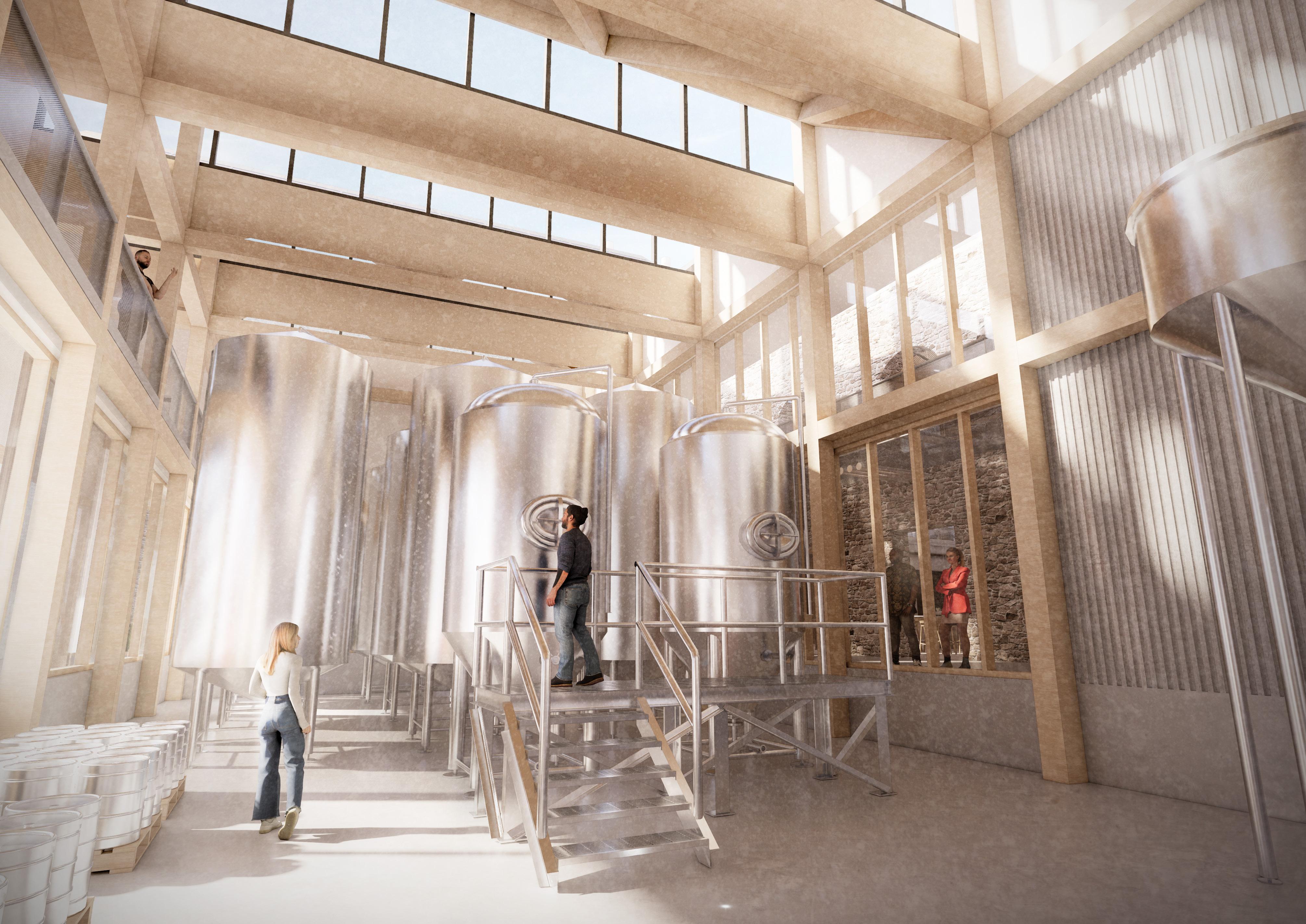 Visual in Brewing Hall


p. 19 1:50 Tectonic Model
Sitting adjacent to the taproom and facing onto the busy public realm to the West of the site sits the Brewing Hall. The tectonic language of this space is about ‘connections’ - opening the space up to both the taproom and public realm to engage the public with the activity occurring within. In line with the overall concept, it can also be viewed as an inflection of the tectonic of the taproom; a heavy brick ‘lid’ sitting over a lightweight base, as opposed to a lightweight roof sitting over heavy masonry walls.
As a result of this, the materiality of the ground and first floors are vastly different; the ground level much more permeable, and the first floor more solid. Continual glazing runs the length of the ground floor, exposing the glulam structure and brewing vessels behind. Galvanised mesh panels provide varying degrees of privacy, and an ever changing play of light and dark within the space. On the contrary, the masonry panels read much heavier; hung from the glulam structure with deep openings punched into the facade.

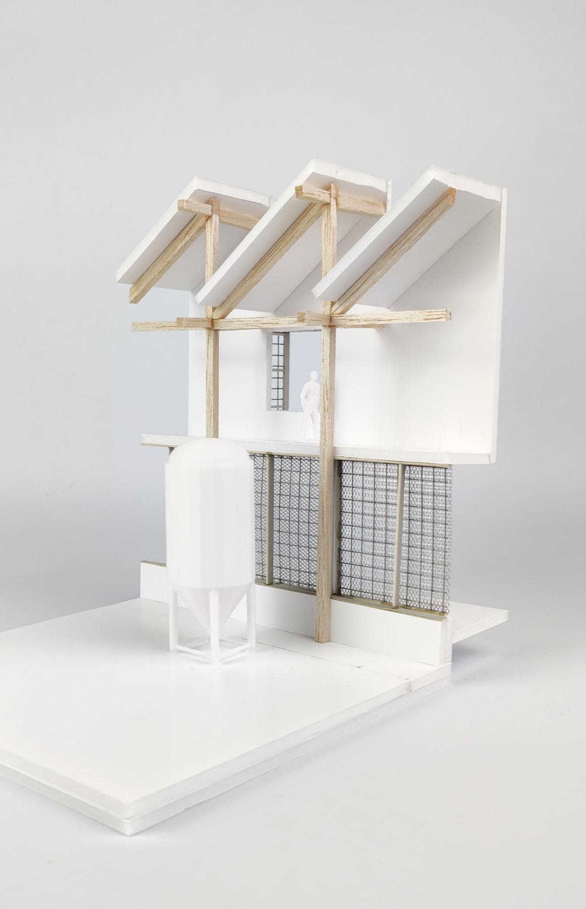

Line of soldier coursed brick to top of wall, bedded in lime mortar 1m x 1m reclaimed brick panel cut from facade of existing demolished building, bedded on 25mm thick concrete backing panel
p. 21 Bay Elevation
A
Sawtooth Roof Gable Detail (A)
Glulam structure (300x500mm)
CLT roof deck
Reclaimed standing seam roof
1 2 3 4 5 6 1 1 2 3 4 5 6
PPC aluminium pressing

Year 4.1 - TED Integrated Design Project
Location: Swindon, UK
Sector: Education
Year: 2023
Our group project in fourth year, the TED Happold Integrated Design Project, placed us in a group with Civil Engineering students and set a complex design brief for a proposal at a much larger scale than any of our previous projects. This year’s brief called for a new HE institute in the town of Swindon, set on a vacant site adjacent to the railway, specialising in two key subjects chosen by the group.
Our group chose to focus on the subjects of Biomedical Engineering and Materials Science; proposing that our Institute works closely with a nearby UoB & UoO research hub called iCAST. Our scheme was developed with the idea of ‘transfers of knowledge’; facilitating spaces of all scales to enable shared learning between all stakeholders of the building - from students and researchers, to staff and public.

p. 23
Connexus
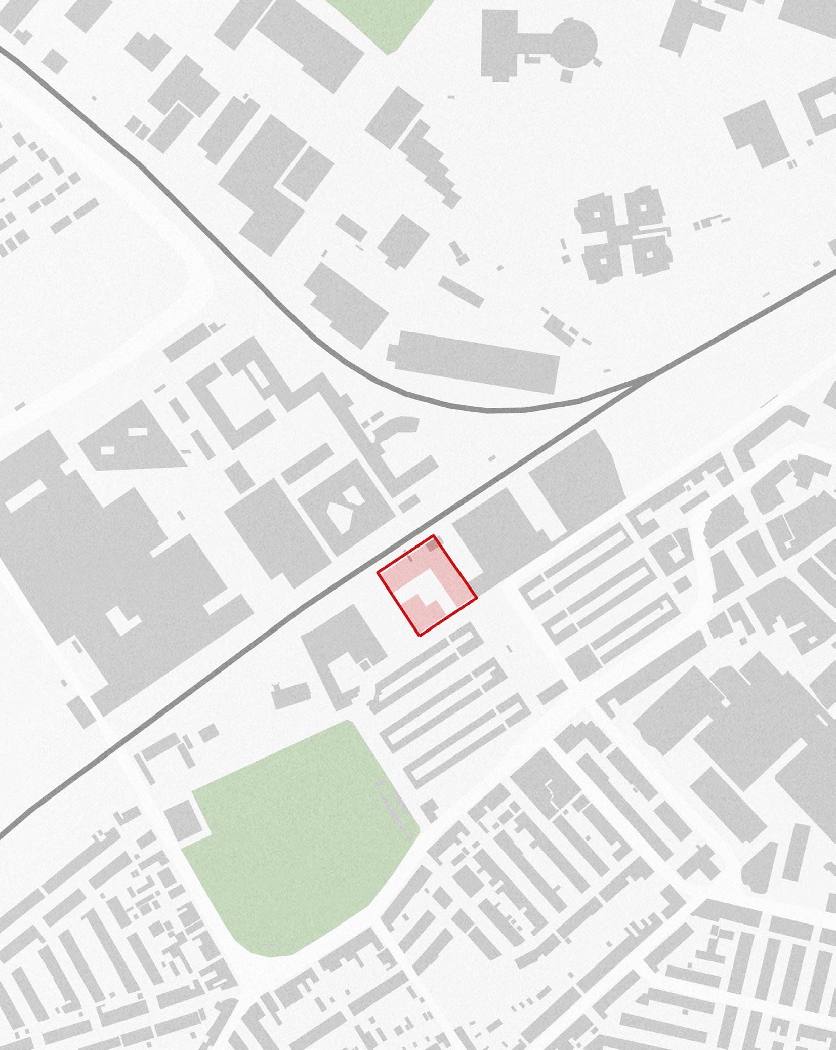
Our brief for our group project was complex; to design a new HE institute in the town of ‘New Swindon’ combined with an industry innovation hub, which together will act as the public face of a regional university. The building was required to facilitate two specialist subjects of our choosing - these were Materials Science and Medical Engineering. The project was required to include a detailed schedule of accommodation, which is summarised below.
Through industry collaboration, the proposal aims to pull new FE students into STEAM fields. The site, Bristol Street Car Park, sits within the now designated Swindon Railway Conservation Area and is in the local vicinity of several significant buildings including the Mechanics’ Institute, Historic England archives and the National Trust ‘Heelis’ building.


Library 24x Classrooms Specialist Subjects
Workshop
124x Bedrooms
Public Connection Dining Hall Auditorium
(By Others)
Figure Ground Image from Group Project

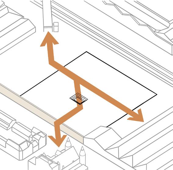


Establishing two key connections through the site. The first is the Mechanics’ Institute to the new bridge adjacent to our site. The second is iCAST to the new public realm.

We introduce the two subject faculties which meet at the corner creating an informal ‘meld’ used for knowledge transfer. The massing is stepped back away from the existing wall.
Using the key axes, we established a route through the site. We connected our ‘heart’, an amphitheatre used for knowledge transfer as well as acting as a rain garden, a key part of the scheme.
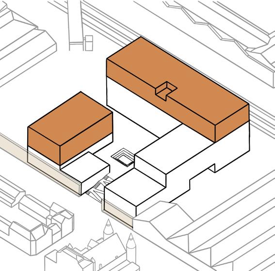
Student accommodation lies on the top floors of the north building, providing a strong facade to the railway. The student library occupies the next floors of the smaller tower.
Our massing has been arranged around the route through the site, creating a central courtyard surrounded by two L-shaped buildings.
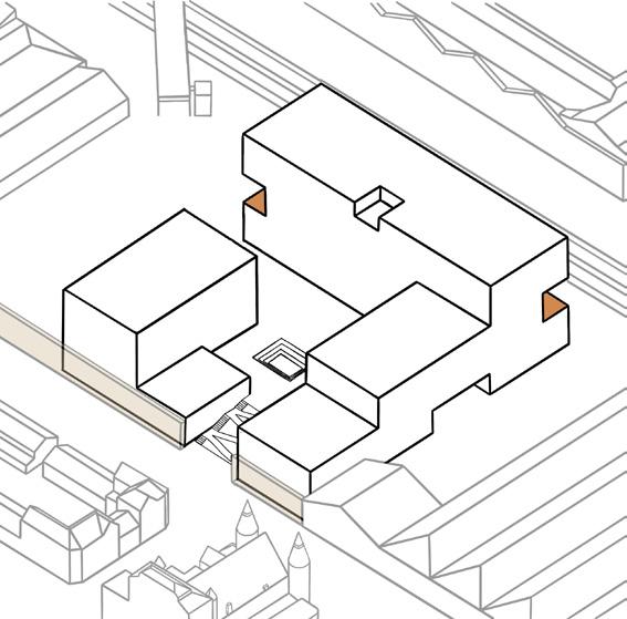
In response to the railway, we have cut out sections of the massing to create depth and interest to onlookers from the trains.
We have a public lower ground level within the existing structure of the site. All public functions are arranged along the main route across the site with auditorium and food hall at either end.

At the top of the smaller tower, we have placed an industry workshop. This is to be used as our Innovation Hub where collaboration is the focus of all activities and knowledge transfer between research and industry is fundamental.
p. 25 Images from Group Project (By Others)
2.
3.
4.
8.
1. KEY AXES
THE ROUTE & HEART
THE MASSING
LOWER GROUND & PUBLIC 5. THE FACULTIES & ‘MELD’ 6. STUDENT LIFE
7.
THE RAILWAY FACADE
THE INNOVATION HUB
N
Our proposal re-imagined a locally available, vernacular material – stone – as a structural exoskeleton, with the building acting as a manifesto for this emerging method of construction. Stone provides many benefits as a material, but is currently ignored in the wider construction sector. Drawing on existing precedents such as 15 Clerkenwell Close (designed by Amin Taha + GROUPWORK, and Webb Yates Engineers), this choice demanded a collaborative approach where structural, architectural and environmental requirements were of equal importance. Our unique structural system, alongside a considered architectural design and rigorous environmental strategies, created a carbon negative building with the capacity to last for generations.
Site Plan
Bristol Street
Bristol - London Railway Line
p. 27 Section A-A Section A-A 0 5 10 15 20 25 1:200 @ A3 Section A-A Key Plan
Auditorium
Library Innovation Hub
Exhibition Space
 Visualisation from ‘Innovation Hub’
Stone exoskeleton beams (500x600mm)
Galvanised steel connection ‘T’ with integrated thermal break positioned within insulation line
Glulam trimmer beam between trusses (200x300mm)
Powder coated aluminium fascia to parapet
Proprietary insulated structural angle (IsoChemie ‘Winframer’) allowing for glazing frame to be positioned within insulation line, so eliminating cold bridging from interface
Multiwall polycarbonate glazing (by Lamilux) with thermally broken frame - U value 0.9 W/ m2K
Horizontal louvres fixed to exoskeleton beams (to suit South East facing facade orientation)
Timber acoustic panels fixed to ceiling (with acoustic insulation between and above timber fins) to suit required reverberation time of less than 1 second
Screed layer over CLT floor (providing vibration dampening, acoustic and thermal mass
Insulated timber cassette panel with rainscreen panels over
p. 29 Innovation Hub Tectonic Section
Detail A (Facade to Roof)
Detail B (Facade to Floor)
Detail A
Detail B
1 2 3 4 6 7 8 9 10 5 1 2 3 4 6 8 7 7 5 1 2 5 6 9 8
The specialist teaching spaces are arranged within distinct faculties with labs on the lower floor and workshops above. Each faculty has a double height atrium and a dedicated stair between the two floors. This creates a sense of identity to each faculty and prevents a ‘copy/paste’ approach. Informal and flexible study spaces are provided between defined teaching spaces to facilitate discussions and “transfers of knowledge” between students, researchers and staff.
Labs and workshops were designed to respect the hierarchy of the grid established by the exoskeleton, with the same linear language continued inside to ensure a cohesive whole.

p. 30
Floor Plan Extract Visualisation of Faculty Study Space LIFTS Going 167 Rise Flexible Study Space (Atrium) Biomaterials Lab Biomechanics Lab Computer Lab WCs Changing Rooms Student Work Store Prototyping Workshop 1 2 3 4 5 6 7 8 1 2 2 3 4 5
Second
Section Through Biomedical Engineering Faculty
Triple glazed rooflight with thermally broken frame
U value 0.9 W/m2K
Rooflights fixed on angled firrings to allow for drainage
Fins framed with softwood battens, voids infilled with acoustic insulation batts
15mm plywood facing to fins (by ‘Purebond’ or similar, containing zero formaldehyde or VOC’s) with routed slots
Recessed shadowgap at joints with integrated LED lighting
p. 31
Rooflight Fin Detail (C)
Glulam posijoist
1 2 8 6 4 Second Floor Third Floor 1 2 3 4 5 6 1 2 3 4 5 6 Detail C
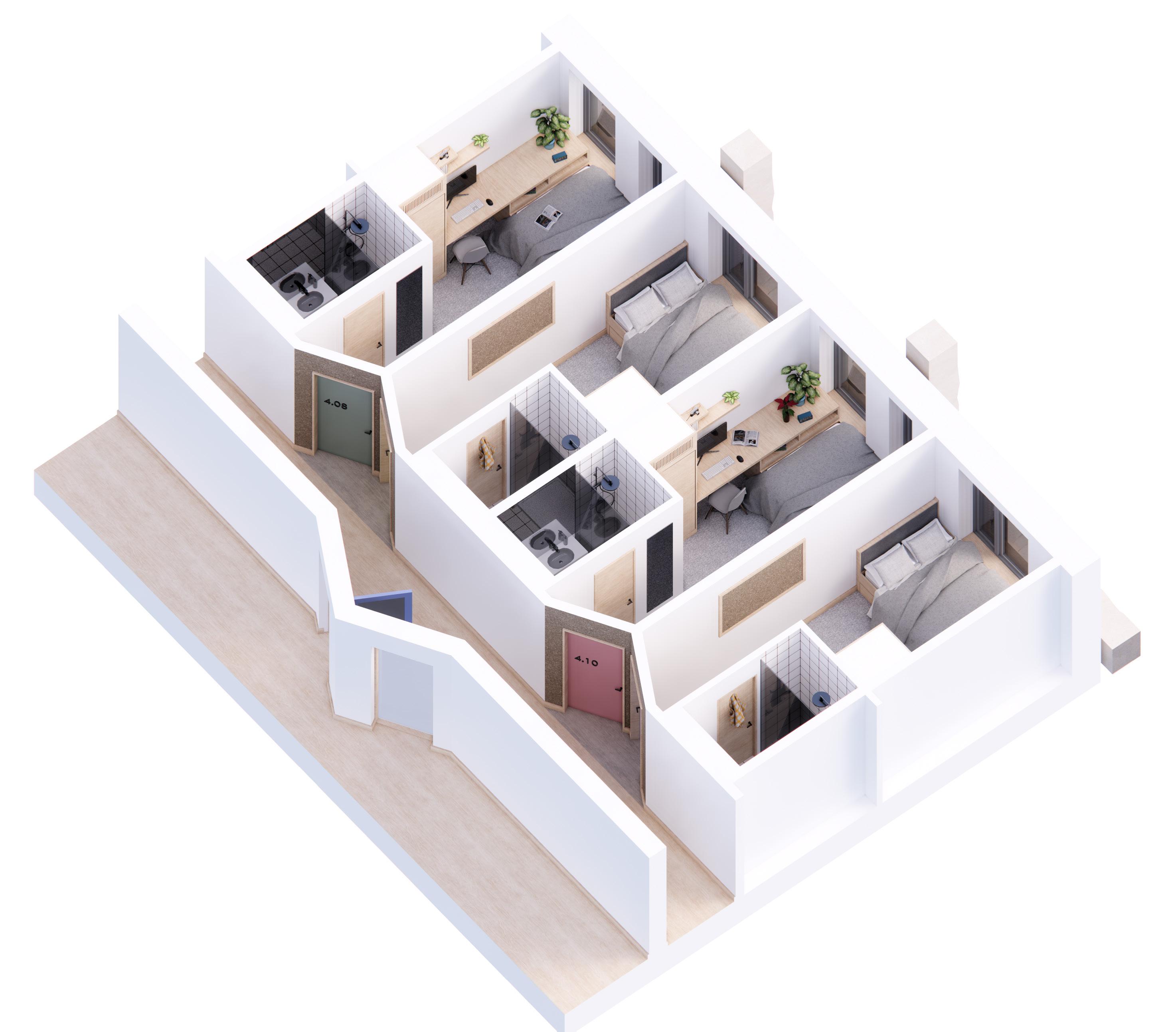
As part of our schedule of accommodation, we were required to include 124 student bedrooms. We designed these with a focus on socialising, providing opportunities for interaction at every level of ‘division’ within the accommodation blocks. To do this, we turned to the concept of streets; at the larger level, providing internal and external shared streets which facilitated socialising between flats. Internally, bridges linked flats across a three storey atrium, creating a community within the student accommodation.
At the smaller scale, we challenged the concept of a corridorseeing this more as a street with flats organised around paired doorways. This creates more intimate connections between individual rooms and their ‘neighbour’, referencing the elevations of Brunels’ GWR Workers Cottages adjacent to the site.

p. 32
Fourth Floor (Student Accommodation) Plan Extract
Visualisation of Internal Student ‘Street’
p. 33
Axonometric of Student Room Cluster

p. 34
Structural Axonometric
Detail A
Detail C
Detail B
N.B: Flooring systems not shown for clarity

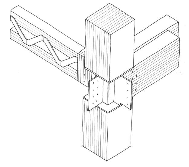
Details drawn by myself, designed in collaboration with group engineers


p. 35
Detail A: Exoskeleton to Primary Beams & Floor Slab
Detail B: Exoskeleton to Secondary Beams
Detail C: Internal Structural Node Connection
Wall Cassette Panels Curtain Walling Rainscreen Cladding Steel Connections Stone Exoskeleton Sheathing Insulation
Exploded Facade Assembly Sketch

Playtime
Year 3.2
Location: Oxford, UK
Sector: Community / Performing Arts
Year: 2022 / 2023
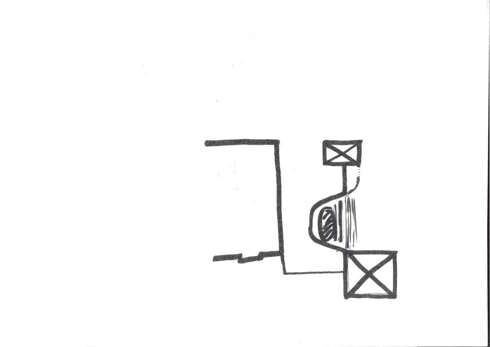
Our main design project of third year revolved around designing a new community theatre within the historic city centre of Oxford. My chosen site was an existing but underutilised building to the north of Bonn Square, which was to be demolished following a hypothetical fire. Sitting at the West end of Oxford’s historic high street and adjacent to the Westgate shopping centre, the proposal evolved from a simple theatre into a multifaceted offering which gave back to the public realm and reactivated the square it faced.
p. 37
Our proposals were required to be designed in response to the needs of a minority / under-represented group, who would utilise the theatre in either a performer or audience role. My proposal focussed on the homeless population of Oxford, with my chosen site (Bonn Square), being the rough sleeping hub of the City Centre.
My scheme incorporated a small hostel which could be used by rough sleepers, and included a communal kitchen, washing, laundry and sleeping facilities. The theatre would act as an extension of an existing local charity - Crisis Skylight - who provide employment and support for homeless and struggling people through the medium of theatre.

According to the 2019 Index of Multiple Deprivation, 10 of Oxford's 83 neighbourhood areas ('Super Output Areas') are among the 20% most deprived areas in England.
The number of rough sleepers in Oxford has increased by 400% since 2012.
In Oxford the average house price of £513,754 is around 17 times the UK average yearly household income of £29,600.
Index of Deprivation (Per Ward) Over Figure Ground
Proposed Site
Oxford City Council
Homeless Oxfordshire
The skyline along Oxford High Street, and indeed throughout Oxford itself, is dominated by spires. Each is used as a wayfinding device, helping users navigate through the city. In the case of the High Street, the towers draw people along its length by providing a dominant feature in the backdrop of each snapshot of the street.
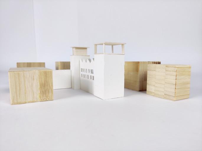
On arrival at Bonn Square, my chosen site, there is a break in this rhythm. Previously, St Peter le Bailey church filled this gap, with the church tower sitting harmoniously with Carfax tower (to the East). But following the demolition of the church in the 1870’s, there has been no new tower on this site. This proposal aims to rectify this, with a new tower element of similar scale to Carfax, which reintegrates the site into the wider context of Oxford.


p. 39
Annotated aerial view of Oxford High Street, highlighting the network of spires along its length. Bonn Square is also highlighted in red
Concept model showing the two towers of the proposed scheme in relation to the surrounding buildings
Along with an auditorium and associated supporting spaces, our proposals were required to provide a ‘Gift to the City’. For my scheme, this took the form of a flexible auditorium, capable of being arranged to suit a multitude of uses. This provided a secondary benefit of the auditorium acting as an extension of the adjacent public square.
p. 40 2 4 5 6 7 Ground Floor Plan N
Ground Floor Plan 01 05 01 02 03 04 05 06 07 08 Entrance Lobby & Reception Cafe Sunken Performance Space Reception Circulation Core Communal Hostel Kitchen Auditorium Laundry Facilities 02 06 03 07 04 08
lectures,
Transverse Stage Thrust Stage
POOR THEATRE... Jerry Grotowski
POOR THEATRE... Jerry Grotowski
Audience near to performers
Audience near to performers
A transverse stage layout which creates an intimate proximity between the performer and the audience. The stage is open to the square, allowing the public to be ‘invited’ into the auditorium. This stage layout facilitates ‘poor theatre’ styles of performances - a term coined by Jerry Grotowski which involves minimal props and a focus on characters and immersion.
More 'traditional' theatre, but still less of a focus on props and sets and more on experimental type theatre. Smaller
More 'traditional' theatre, but still less of a focus on props and sets and more on experimental type theatre. Smaller
Covered Market Space
POOR THEATRE... Jerry Grotowski
POOR THEATRE... Jerry Grotowski
Audience near to performers
Audience near to performers
End on for other activities - lectures, seminars, talks etc.
Visiting Exhibitions or Events
End on for other activities - lectures, seminars, talks etc.
audience size so much more intimate
audience size so much more intimate
A thrust stage with seating on three sides. The stage is closed off from the square and provides an intimate relationship between the performer and the audience. This setup can facilitate both traditional and experimental types of theatre.
The size of the auditorium provides ample room for pop up markets, or similar events. The scope of these events can be expanded to take over the entirety of Bonn Square, breathing new life into the public space.
Alternatively, the space could be utilised for visiting art exhibitions or events, with the public easily able to interact with any exhibits once the space is opened to the square.
p. 41
p. 42 First Floor Plan 2 4 5 6 7 8 9 13 14 15 16 N First Floor Plan 01 01 05 Auditorium Hostel Bedrooms Circulation Core Wash Facilities Dressing & Green Rooms Locker Room Costume Store 02 02 06 03 03 03 03 04 05 07 05 06 06 07 04
p. 43 Section B-B 1:100 @ A3 0 2.5 5m B B
Long Section (A-A)
100mm reclaimed brickwork in Flemish bond
200mm wood fibre insulation batts
140mm ‘Porotherm’ thin joint blockwork
12mm wet plaster finish
Typical Ground Floor Buildup (B):
100mm reclaimed brick floor finish
75mm screed with UFHS to offices etc.
150mm rigid insulation
50mm proprietary waterproof membrane and spacer (Type C)
150mm reinforced concrete slab
Proprietary Type A waterproofing membrane
25mm sand blinding
150mm compacted hardcore NTS
Typical Roof Buildup (C):
Zinc standing seam roof
18mm plywood carrier board
50mm ventilated void
Proprietary breather membrane
75mm wood fibre insulation batts
18mm plywood
75mm wood fibre insulation batts
350mm x 150mm Glulam structural truss
Proprietary vapour control layer
100mm acoustic insulation batts
25mm open boarded timber cladding
p. 44 M 0 1 2 3 4 5 M Tectonic Section
Key Plan
Typical Wall Buildup (A):
Rehearsal Space
Dressing Rooms Corridor
Auditorium
Entrance Lobby
Sunken Black Box Theatre Space
W.C’s


p. 45
Final Proposed Bay Elevation
Proposed Elevation Studies
Existing Street Elevation
p. 46
East
East
1:100 @ A3 0 2.5 5m
Proposed
Elevation
Elevation
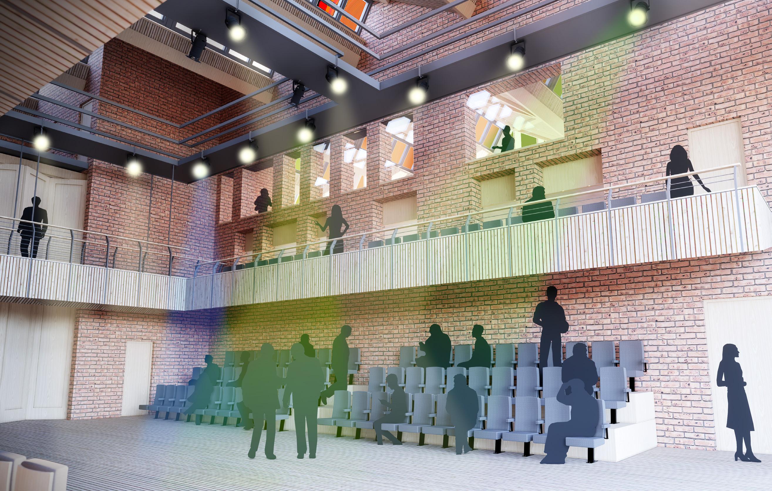
p. 47
Visualisation of Auditorium

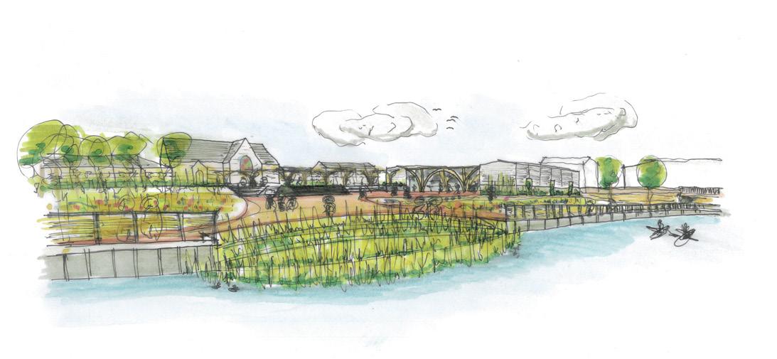
River Avon 1 1 2 2 3 4 5 6 6 10 7 8 9 2 3 4 5 6 7 8 9 10 Cycle Path Windsor Bridge St Johns Church Samaritan’s Centre Allotments Greenhouse Covered Market Pedestrianised Zone Cookery School Image from Group Project (By Others)
Biophillia
Year 3.1
Location: Bath, UK
Sector: Community / Public Space
Year: 2022 / 2023
Biophillia is a term that defines our innate affinity to connect with the natural world. As a result of urbanisation, we have lost our connection with nature, and more recently, with our neighbours and wider communities.
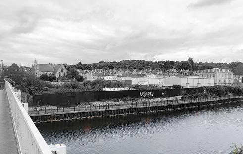
This three week group project in third year challenged us to redevelop a dilapidated brownfield site in the western quarter of Bath. Our proposal revolves around the core narrative of regeneration; regenerating the site and the community in tandem. Clear connections are developed to the neighbouring Church and Samaritans centre, providing new facilities for those in need.
p. 49
RECLAIM
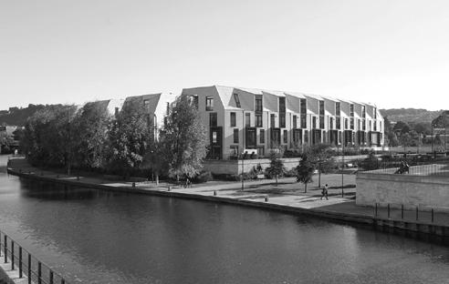
The existing brownfield site is reclaimed in preparation for remediation.
CONVERT
After the initial remediation phase, the existing warehouses are converted and associated hard landscaping works completed.

ASSESS
At the end of the anticipated design life of the existing warehouses, the site will be assessed to determine how the later stages of development should be carried out.
REDEVELOP
If a more suitable use for the site is identified at the end of the design life of the current proposals, the site can be redeveloped to facilitate another use.

REMEDIATE
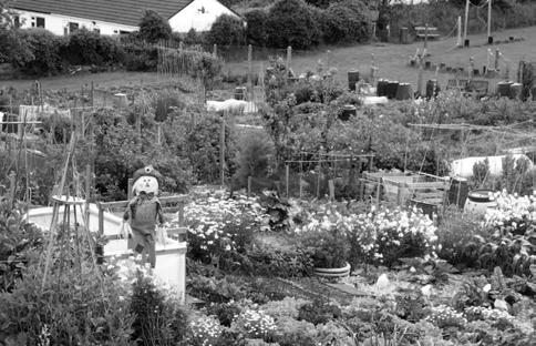
An extended programme of bio- and phyto-remediation breaks down and removes contaminants from the soil, through targeted planting schemes.
CULTIVATE
After the full remediation programme is completed, planting pivots to crops to be used in both the cookery school and wider community.

MAINTAIN
If proposals are shown to have a positive impact to the local community, and no other uses are identified for the site, then further maintenance and upgrades can be provided to extend the design life of the scheme.
p. 50
2022
DECISION
2029
2042 2024
2034

The intention of the proposal is to work closely with the adjacent Church and Samaritans charities to provide additional facilities for use by people in need.
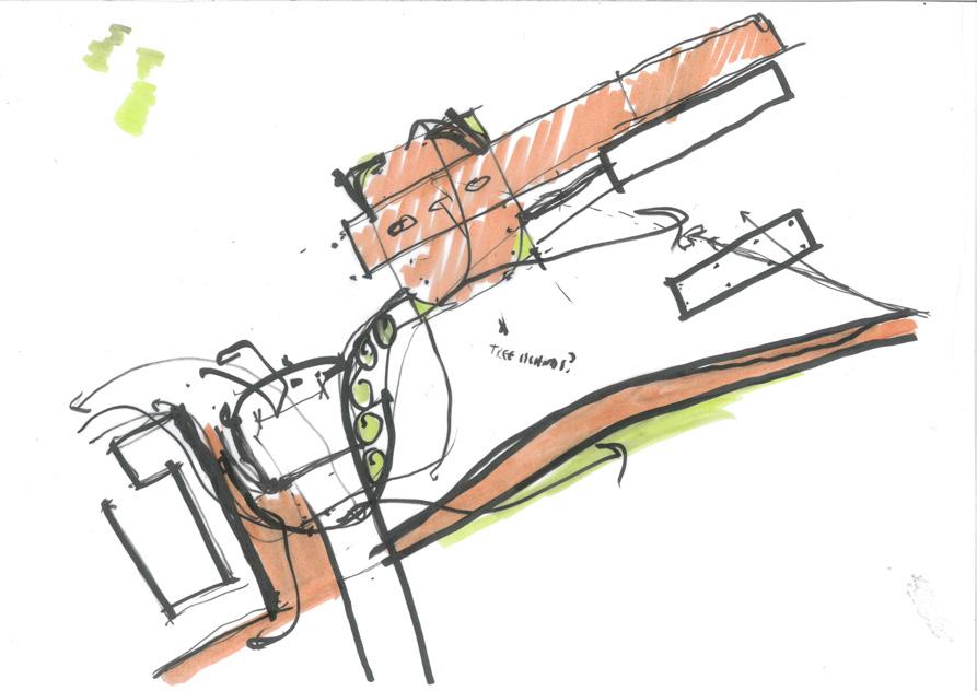
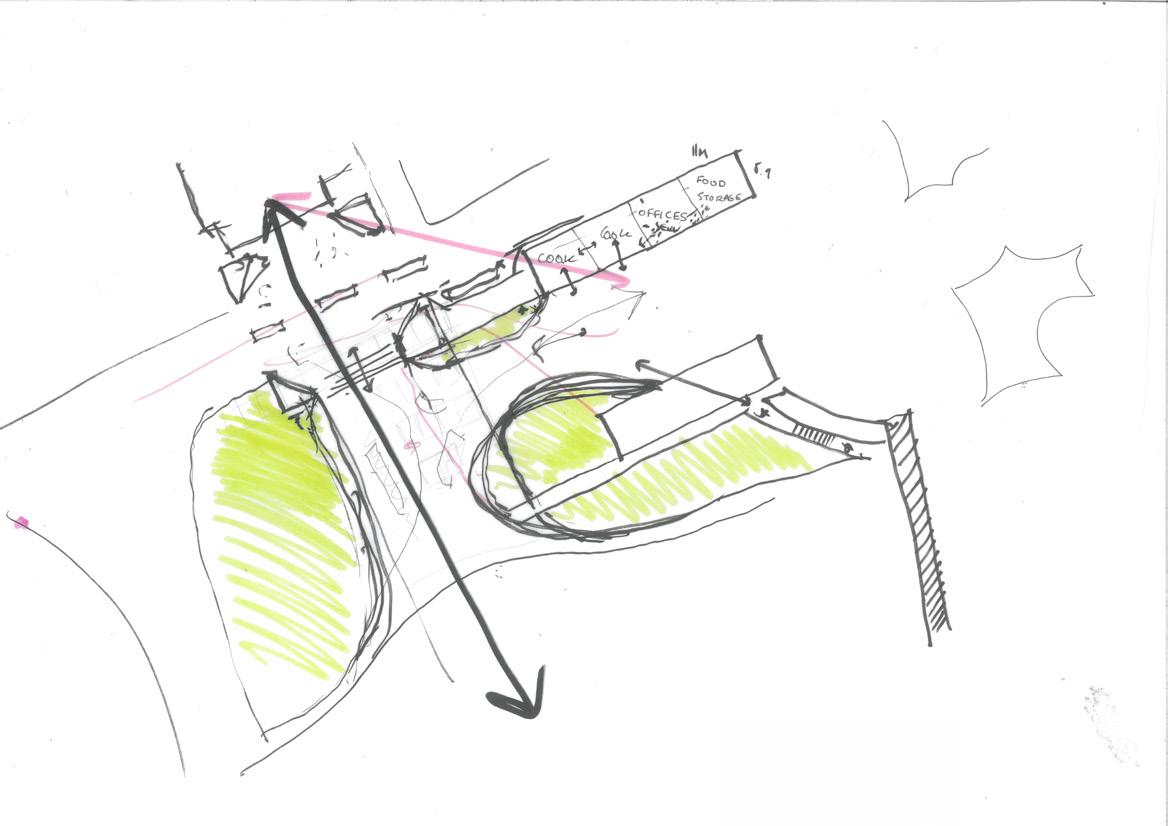
The masterplan for the site was developed through creating a strong axis between the important elements on the site; namely the Church (to the North), warehouse buildings (t0 the East), and river (to the South). Pedestrianising a section of road outside the Church facilitates a more direct connection to our site; creating an informal square which can be used for events and gatherings.
The site contained two existing portal framed warehouses, which will be converted into a cookery school and greenhouse to supplement the proposed allotments. These three elements will come into use after the remediation measures are completed.
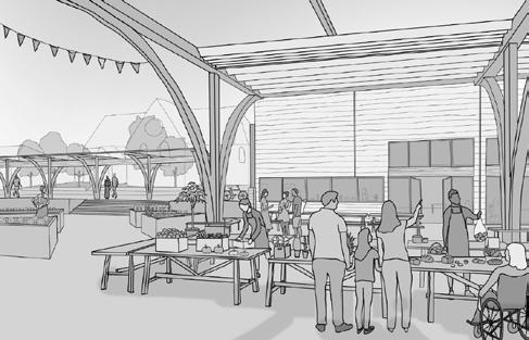
In tandem with this, a lightweight timber canopy will be created between the two warehouse buildings, providing a flexible multi-purpose space for food events, performances, markets or simply as a covered seating area.

p. 51
Masterplan Development Sketch
Design Development Sketches
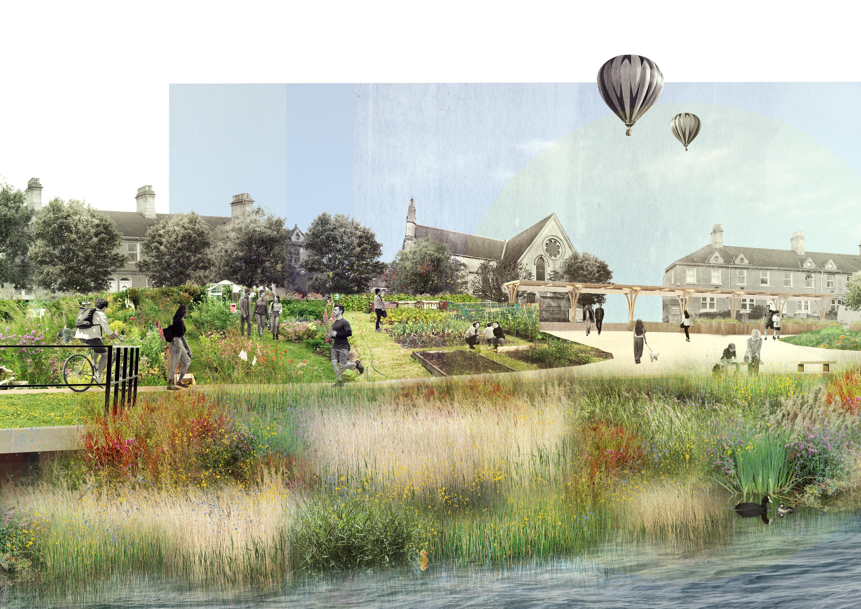

By making plants & wildlife a dominant force within the public realm, the lines between natural and urban are blurred; nature becomes part of the spatial experience for those moving through the urban environment. Both the allotment spaces and reed bed will change throughout the seasons, as will the types and abundance of wildlife - making for an ever changing space which will bring benefits to the wider community for years to come.
Visualisation from River Avon

Medical Centre
Year 2.2
Location: Bristol, UK
Sector: Healthcare
Year: 2021 / 2022
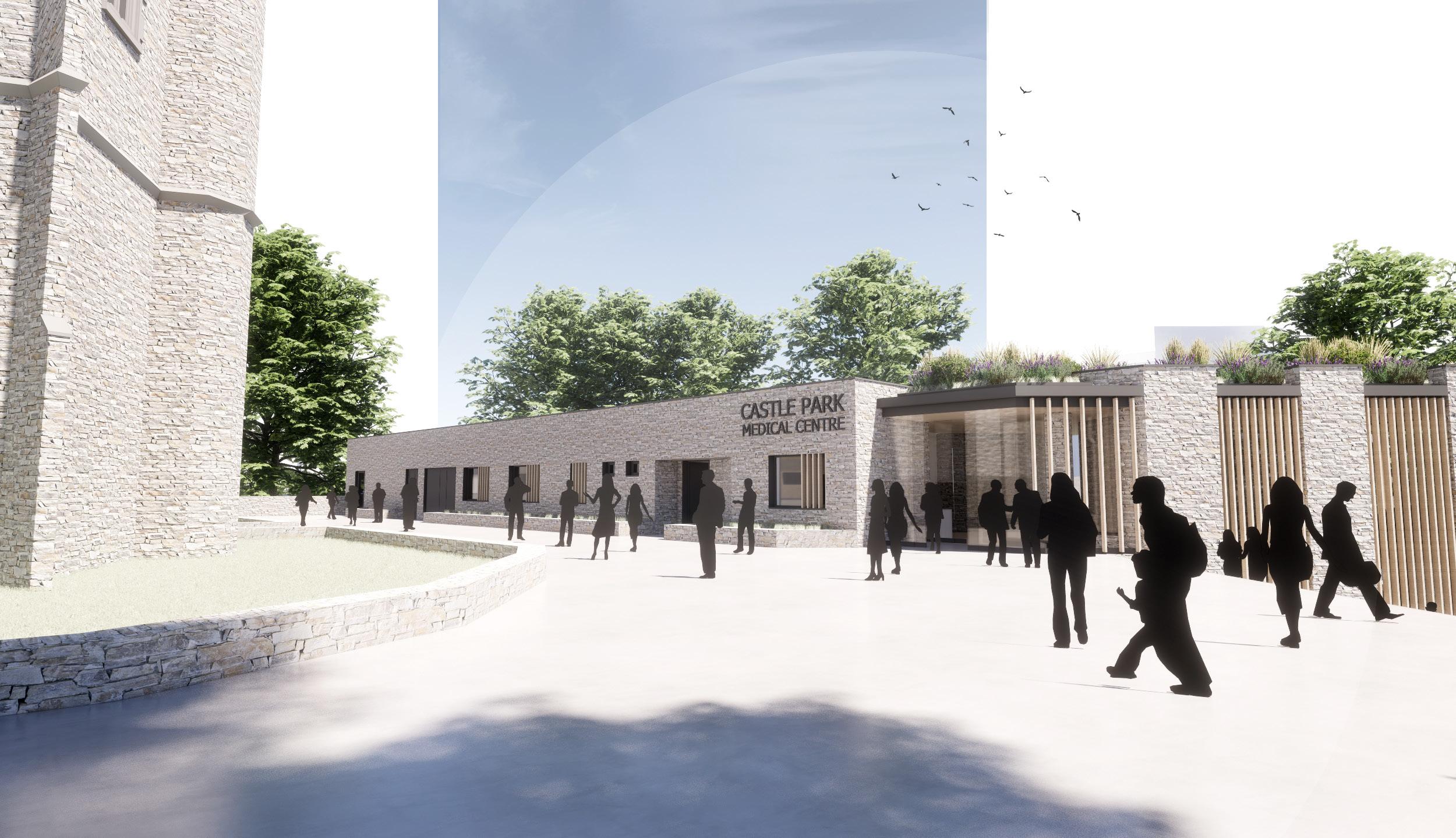
My main second year project focused on providing a new medical centre set within Castle Park, Bristol. The building was set within a complex site context, including a Listed church tower (St Mary le Port) which sits adjacent to the Northern facade. The site was previously occupied by the vacant Bristol Law Courts, so this redevelopment provided the opportunity to enhance the public realm at the same time.
The scheme aims to create a place of calm and healing within the busy city context, through defined boundaries between public and private. At its core, the proposed building is one which wishes to heal the users as much as the doctors and nurses who work within it.

p. 55
The initial move was to insert a solid element along the Northern boundary of the plan area to separate the adjacent public space from the private spaces within the medical centre. This element was cranked to run perpendicular to the desire line of public movement running between the church tower and the nearby bridge.
The L shaped plan sets up two strong axes which run the length of the mass, with horizontal circulation occurring along these axes and both views/permeability and vertical circulation provided at the ends.
The two entry points into the building are positioned at the intersection of the two axes (principal entry on the upper storey, and a secondary entrance on the lower storey).

A partially sunken mass is inserted to the South of the courtyard, bounded by the new wall. The single visible storey on the courtyard side reduces the building’s impact on this space.
The mass also creates three distinct courtyard spaces each with different characters; the West space focused on movement, the North stiller and focused on the church, and the South much more private and calming.
The plan allows for a clean distinction of spaces over both floors; with served spaces (consulting rooms etc.) pushed to the front of the plan to benefit from the connection to the private courtyard and the staff and BoH spaces placed at the rear of the plan.


The waiting room is located at the West end of the plan to benefit from the Southern views down river and the adjacency to the entrance.


To divide the consulting spaces thick masonry fins are inserted perpendicular to the main axis; these provide a feeling of enclosure and separation and improve patient privacy.
03.
05.
01. L Shaped Wall Inserted to Provide Privacy
Axes and Entry
Served and Service Spaces
06.
Perpendicular Fins
04.
Courtyards
PUBLIC PRIVATE SERVED SERVICE High Street
02.Sunken Mass Inserted to South
The proposed building aims to sit subserviently to the existing church tower, ensuring the spire remains dominant in the surrounding context. To create a calm internal space in a public dominated realm, the building takes the form of an L shaped plan which provide separation from the existing public plazas. One of the legs of the L is oriented off angle to face directly South – the building’s edge framing the view of the river.
The proposal is spread across two storeys, with the lower floor embedded into the topography of the site. In response to my site analysis and the need for increasing tiers of privacy throughout the spaces, the plan developed into a linear spatial arrangement – with the levels of privacy increasing as the users move through the building.

Refer to next project for details of Housing Scheme.
p. 58 9 5 4 2 7 8 7 6 5 4 3 2 1 9 1:150 @ A3 Lower Ground Floor Plan 01 07 13 Entrance Lobby Practice Manager’s Office Treatment Room Store Interview Room Consulting / Nurses Room Examination Room Plant Room Reception Medical Waste Storage Waiting Area Cleaners Cupboard Medical Records Store Pharmacy W.C Pharmacy Store Staff Common Room / Kitchenette Complimentary Services Space 02 08 14 03 09 15 04 10 16 05 11 17 06 12 18 03 05 05 05 05 14 09 18 13 14 17 17 17 17 16 16 16 16
p. 59 24 23 22 21 20 19 1011121314151617 9 8 7 6 5 4 3 2 1 24 23 22 21 20 19 18 17 16 15 14 13 12 11 10 9 7 5 4 2 18 1:150 @ A3 Upper Ground Floor Plan 01 07 13 Entrance Lobby Practice Manager’s Office Treatment Room Store Interview Room Consulting / Nurses Room Examination Room Plant Room Reception Medical Waste Storage Waiting Area Cleaners Cupboard Medical Records Store Pharmacy W.C Pharmacy Store Staff Common Room / Kitchenette Complimentary Services Space 02 08 14 03 09 15 04 10 16 05 11 17 06 12 18 01 07 13 14 02 08 03 09 15 15 04 10 05 05 05 05 11 06 12 12 12
Detail Section Calculating Depth of Shading Devices
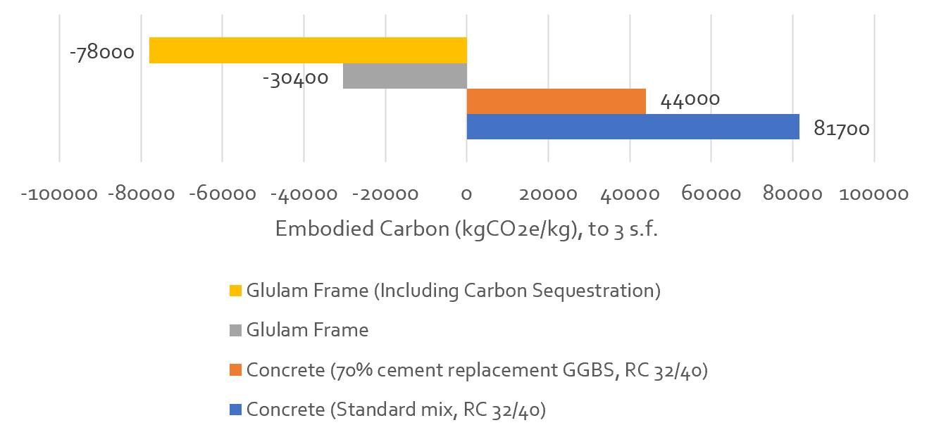
Embodied Carbon Calculation of Structural Elements

Graph Highlighting Space Heating Requirements Against Passive Internal Gains

Ventilation and Daylighting Strategy Section
p. 60
PrEvailing wind from South & South wESt
y max = 62o 21 / 06 y max = 16o 21 / 12 750mm 1415mm 75% of window shaded natural vEntilation daylighting mEchanical vEntilation
no Sky linE (to ridgE of houSing adjacEnt)
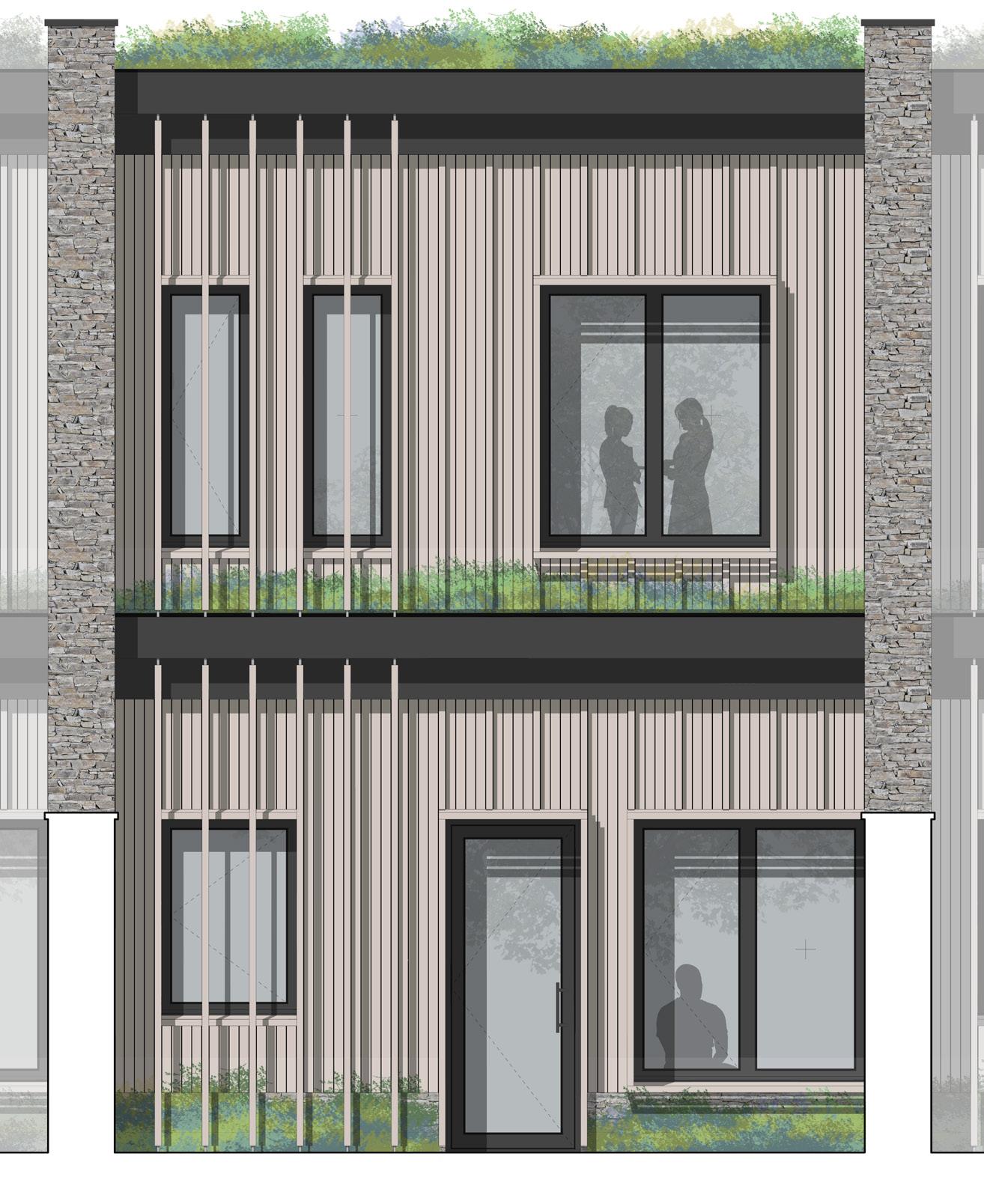
p. 61 Upper Ground Floor +4.000 Lower Ground Floor +0.000 A - Flat Roof Construction 40mm drainage board Geotextile membrane 100mm min. soil substrate with native vegetation (planting not shown) B - External Wall Construction 75mm x 25mm vertical cedar cladding fixed with zinc coated s/s lost head nails left untreated. Replace with projecting 50mm x 75mm vertical cedar board every 5 no. boards as per detail elevation Detail Section A-A 1:25 @ A1 Detail Elevation 1:25 @ A1 A3 A1 A2 A4 A5 A6 A7 A8 A9 A10 A11 A12 A13 D1 D2 D4 D3 D5 D6 D7 E2 E1 E3 E4 E5 E6 E7 E8 E9 E10 C1 C3 C4 C5 C6 C7 C8 C11 C2 C9 C12 C13 C14 C10 0 1 2m 0 1 2m B1 B2 B3 B4 B5 B6 B7 B8 B9 B13 B14 B10 B11 B12 F5 F1 F2 F6 F3 F4 F7 F8 F9 F10 F4 F11 F12 Insulation batts - acoustic or wood fibre Rigid PIR flat roofing insulation (providing suitable adhesion for single ply membrane) Closed cell XPS rigid insulation (waterproof, suitable for use below DPC) Membrane Key: Single ply membrane Breather membrane Vapour control layer DPM's, DPC's and cavity trays G9 G10 G1 G2 G3 G6 G12 G5 G11 G7 G8 G4 A1 A2 A3 B1 H6 H4 H1 H2 H3 H7 H5 H8 H9 H10 D6 Seperation membrane Note: Downpipes concealed within stone walls to either side of each bay Upper Ground Floor +4.000 Lower Ground Floor +0.000 A - Flat Roof Construction 40mm drainage board Geotextile membrane 100mm min. soil substrate with native vegetation (planting not shown) B - External Wall Construction 75mm x 25mm vertical cedar cladding fixed with zinc coated s/s lost head nails left untreated. Replace with projecting 50mm x 75mm vertical cedar board every 5 no. boards as per detail elevation Detail Section A-A 1:25 @ A1 Detail Elevation 1:25 @ A1 A3 A1 A2 A4 A5 A6 A7 A8 A9 A10 A11 A12 A13 D1 D2 D4 D3 D5 D6 D7 E2 E1 E3 E4 E5 E6 E7 E8 E9 E10 C1 C3 C4 C5 C6 C7 C8 C11 C2 C9 C12 C13 C14 C10 0 1 2m 0 1 2m B1 B2 B3 B4 B5 B6 B7 B8 B9 B13 B14 B10 B11 B12 F5 F1 F2 F6 F3 F4 F7 F8 F9 F10 F4 F11 F12 Insulation batts acoustic or wood fibre Rigid PIR flat roofing insulation (providing suitable adhesion for single ply membrane) Closed cell XPS rigid insulation (waterproof, suitable for use below DPC) Membrane Key: Single ply membrane Breather membrane Vapour control layer DPM's, DPC's and cavity trays G9 G10 G1 G2 G3 G6 G12 G5 G11 G7 G8 G4 A1 A2 A3 B1 H6 H4 H1 H2 H3 H7 H5 H8 H9 H10 D6 Seperation membrane Note: Downpipes concealed within stone walls to either side of each bay
Construction Section & Elevation (Drawn Originally at 1:20 @ A1)
Detailed
p. 62
Visualisation from Church Courtyard

p. 63
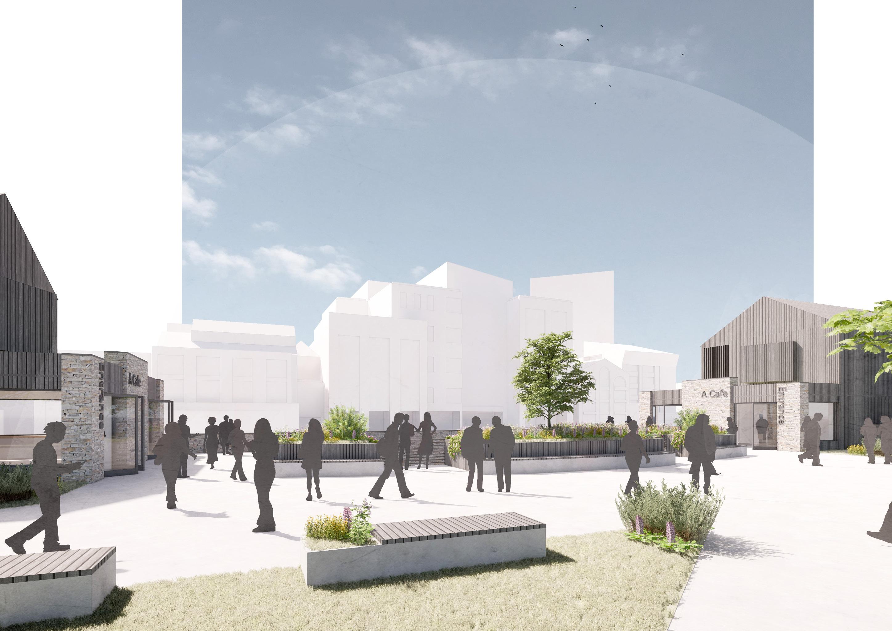
Visualisation of South Facade
City Centre Housing
Year 2.1
Location: Bristol, UK
Sector: Residential
Year: 2021 / 2022
This short group project in Second Year challenged us to design a small housing development set within Castle Park, Bristol. Context was key to this project, with the proposals needing to respond sensitively to the adjacent historic buildings, as well as sit comfortably next to a busy public park.
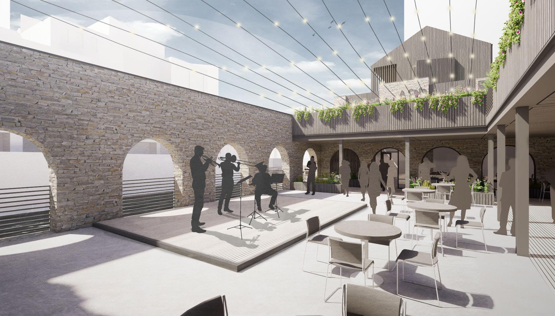
The proposal made use of the existing connection with the site to the River Avon by creating two short runs of 4 houses built into the existing river wall, separated by a sunken courtyard. This courtyard was in turn serviced by two cafés located on the ends of each run of housing. The intention was to create a public offer which was ‘given back’ in exchange for the housing, so better integrating the scheme into the very public context.

p. 65

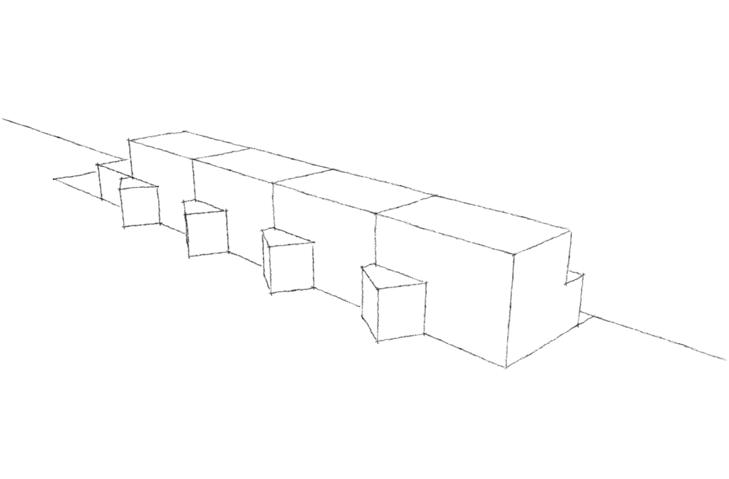
01. Single Mass Interacting with River
Public path pushed behind to provide privacy & views to dwellings.

Creating public space between the two masses and reconnecting the park behind to the river. This also provides a place to pause along the path - something which is currently not provided.


Terraces split to set up strong facade rhythm, responding to opposing buildings.

Balcony recessed into main floor, angled to face direct South and accentuating the view down river.


Internal arrangement organised around a central core, which divides the spaces into a South facing living/sleeping zone and a service zone to the North.

Lower storey built into existing wall allowing views from the park over to opposite roofs and the rising city beyond.
Single storey mass peeled back from main facade line to highlight entrance; low wall continues to form ‘buffer’ space between public and private.
p. 66
02. Mass Pulled Apart
03. Mass Sunk into Wall
06. Entrance
04. Terraces Split into Three
07. Spaces Organised around Central Core
Massing from Approach (NW)
Massing Along River (SSW)
05. Forming a Balcony
p. 67
Visualisation of Sunken Courtyard
p. 68
Floor Plan 0 5 10 M N Ground Floor Plan Lower Ground Floor Plan Detailed
First
Plans on Adjacent Page
Leadengate Fields
New Private Dwelling (PMA)
Location: North Devon, UK
Sector: Residential
Year: 2022
Status: Under Construction
This project was undertaken during my professional placement in the first half of 2022.The client asked us to replace an existing dilapidated prefabricated holiday cottage with a new contemporary dwelling, located within the popular seaside town of Croyde, in North Devon.
The site was incredibly small for the size of building the client was looking to build. The proposal was developed around the idea of two linear pitched roof masses containing the living and sleeping spaces, linked by a small circulation ‘core’. This strategy helped to reduce the impact of the building on the neighbouring dwellings whilst maximising the available space on site.
I was involved in this project from Stages 0 - 4 (I left PMA during the Tendering period). I produced all drawings for this project, including the full tender pack and written specification, and liaised directly with the client & design team throughout.

p. 85
p. 86 PROJECT TITLE DRAWN BY DATE DRAWING NO 8 Leadengate Fields Proposed Ground Floor Plan 1:100 @ A3 JG April 2022 21105_P_03 THE OLD SAIL LOFT PAIGES LANE BARNSTAPLE EX31 1EF T: 01271 377776 Mr P Forbes CLIENT SCALE DRAWING TITLE Replacement Dwelling LOCATION Croyde EX33 1PB Note: This drawing is protected under copyright and whole or in part without the Architects' consent Peregrine Mears Architects Ltd accept no responsibility appointed to provide full architect's services under Engagement Any discrepencies must be reported commences Drawing Status: Do not scale from this drawing Planning NOTES: GIA reduced and soft landscaping LPA and GPC comments A 28/06/2022 RL RL rwp rwp rwp rwp rwp rwp RL RL Existing fence forming site boundary Proposed storage shed (approx 1.5m x 2m TBC by client) clad in timber to match new dwelling Existing bank forming boundary to adjacent plot with new planting to enhance screening between properties P R I V A T E R O A D 2 no parking spaces (increase over existing allocation of 1 no parking space) External timber deck to North West corner of plot Living / Kitchen / Dining Space Utility Entrance Hall Built in bench seat to entrance hall with coat storage etc adjacent Full height glazing with sliding doors providing access to timber deck Bedroom 2 Exposed timber rafters to vaulted ceiling Bathroom Ensuite Master Bedroom Vaulted ceilings to both bedrooms External shower adjacent to entrance External Deck Entrance Outline of previous dwelling (now demolished) shown red dashed 2550mm 2750mm 3300mm 1300mm 1225mm 4000mm Sliding doors providing access from master bedroom onto external deck Strip rooflight over hallway A A 2825mm 7105mm Fireplace on feature plinth against gable wall FFL +23.400 B B 3300mm Electric car charging port adjacent to entrance door Open frontage and grass verge to Leadengate Fields maintained as existing arrangement in accordance with Sections 7.5 & 7.7 of the Leadengate Design Guide New planting proposed adjacent to proposed building to soften edge 0 1 2 3 4 5 10m Proposed Ground Floor Plan 1:100 @ A3 Sunpath Diagram Summer Solstice (21/06) 13:20 21:35 16:10 Winter Solstice (21/12) shown GIA Comparison: Existing: 51.8m2 GIA Proposed: 72m2 GIA (<72.5m2 limit) This increase in GIA is compliant with the recommendations of the Leadengate Design Guide Section 7.11b 7.11b (i): Floor area of existing + 40% = 51.8 x 1.4 = 72.5m2 GIA 7.11b (ii): Floor area of existing + 40% of curtilage (excluding offroad parking - 1 no space existing) = 51.8 + (124*0.4) = 101.4m2 GIA Ground Floor Plan (Originally 1:100 @ A3)

p. 87 External Visualisation
p. 88 PROJECT TITLE Mr P Forbes CLIENT Replacement Note: This drawing is whole or in part without Peregrine Mears Architects appointed to provide Engagement Any discrepencies commences Drawing Status: Do not scale from this Technical NOTES: Drawings A 30/06/2022 Roof B 07/07/2022 Wall amended General C 29/07/2022 Detail D 11/08/2022 01 GA Section A-A 1:20 @ A1 RG01 Kitchen / Living / Dining RG02 Hall RG07 Bedroom 2 O A B C D 2400mm 2490mm 195mm 255mm 2815mm 2708mm 2325mm 2940mm 150mm Min 150mm Min 4135mm 2940mm 4130mm 440mm 430mm 1660mm 1720mm L10/25 Schuco AWS70 aluminium double glazed units Timber lintels to S.E design details and specification R10/11 100mm PPC aluminium half round gutters concealed behind cladding Q10/30 Linear slot drain to base of full height glazing installed in weak mix concrete haunching to manufacturers details connecting to proposed below ground drainage system Foundations to S.E design details and specification Built in bench seat to hallway lined with 45x18mm PAR Western Red Cedar to match feature wall opposite Refer to PMA drawing 21105_T_30.02 for details 20.01 RT02 20.01 FT01 20.01 RT01 20.01 WT02 20.01 WT03 20.01 WT01A 20.01 RT02 20.01 FT01 V90/312 GB Sol Solar Slates to West facing roof pitches installled in accordance with manufacturers details and specification FFL: + 23.400 AOD TOS: + 23.155 AOD 23.01 02 01 23.01 02 25.03 03 25.03 21.02 01 03 21.01 04 23.01 23.01 02 23.02 04 23.02 02 T.O .B: + 23.380 AOD T.O .B: + 23.605 AOD L10/45 Double glazed rooflight on insulated kerb installed as manufacturers design and specification V90/312 - GB Sol Solar Slates to West facing roof pitches installled in accordance with manufacturers details and specification 4230mm 1875mm 3615mm TOS + 26.040 AOD TOS + 27.070 AOD TOS + 27.070 AOD General Notes: All drawings to be read Specialists/Consultants appropriate All sizes of structural steelwork joists/rafters Engineer's design details reported to the Architect Dimensions are given otherwise Dimensions surfaces in doubt etc are to be checked S H CO Mains wired Mains wired Carbon Monoxide Smoke and heat alarms EN 14604 Alarms to Ceiling mounted smoke and between heat detectors All alarms to be wired standby power supply capacitor to BS 5839-6 Escape Window B1 Diagram IC Surface water IC Foul drainage Back inlet gully BIG Linear slot Drawing Key: Recirculating specification Drawing Series Series 10: GA Series 11: GA Series 12: GA Series 20: Construction Point of connection investigated The site is within an Protection Damp Proof Visqueen 'R400' radon approved All to be specifications and written Radon: Series 14: Building Series 21: Floor Series 22: Wall Series 23: Roof Series 25: Glazing Series 30: Finishes Series 31: Sanitaryware Series 40: Electrical Eastern Boundary Details TBC SVP rwp rwp rwp rwp RG03 Utility RL Over RL Over RG04 Bedroom RL Over RG05 Ensuite RG06 Bathroom WG02 EDG02 WG04 WG05 D04 ASHP Loft Hatch Over RL Over RG07 Bedroom RG01 RG02 Hall A GA Construction Section (Originally 1:20 @ A1)
Slab Edge Detail (Originally 1:5 @ A1)
Eaves Detail (Originally 1:5 @ A1)
Eaves Detail (Originally 1:5 @ A1) Flat Roof Verge Detail (Originally 1:5 @ A1)
p. 89 PROJECT TITLE 8 Leadengate Fields Slab Edge Details (Sheet 1 of 2) Mr P Forbes CLIENT DRAWING TITLE Replacement Dwelling LOCATION Croyde EX33 1PB Note: This drawing is protected under copyright and may not be reproduced in whole or in part without the Architects' consent Peregrine Mears Architects Ltd accept no responsibility for works on site unless appointed to provide full architect's services under the RIBA Conditions of Engagement Any discrepencies must be reported to the Architects before work commences Drawing Status: Do not scale from this drawing Technical Design NOTES: Notes amended TOB spot height added Membrane sealing details added Drawings amended to coordinate with S.E design A 12/08/2022 JG General Notes: All drawings to be read in conjunction with all other PMA and Specialists/Consultants Drawings Details Schedules and Specfications as appropriate All sizes of structural members noted on the drawings are indicative only all steelwork joists/rafters lintels slabs masonry etc are to be to Structural Engineer's design details and specification Any discrepancies or clashes are to be reported to the Architect as soon as possible Dimensions are given to structural components/openings unless noted otherwise Dimensions coloured blue are reference dimensions taken to finished surfaces If in doubt ask All fabrication dimensions for windows doors steelwork etc are to be checked and confirmed on site prior to fabrication S H CO Mains wired smoke alarm detector Mains wired heat alarm detector Carbon Monoxide alarm detector Smoke and heat alarms to be linked and mains operated to conform with BS EN 14604 Alarms to be positioned to BS 5839-6:2004 Ceiling mounted smoke detectors to be positioned 300mm away from walls and between heat detectors to be between 25mm 150mm below the ceiling All alarms to be wired on an independant circuit and they should both have a standby power supply such as battery (rechargeable or non-rechargeable) or capacitor to BS 5839-6 Escape Window openings in accordance with Approved Document B1 Diagram .10 IC Surface water inspection chamber IC Foul drainage inspection chamber Back inlet gully BIG Linear slot drains to thresholds Drawing Key: Recirculating cooker hood above AGA to client specification ventilation rate min 13l/s Drawing Series Key: Series 10: GA Plans Series 11: GA Sections Series 12: GA Elevations Series 20: Construction Buildups Point of connection to the existing SWW combined sewer to be investigated and confirmed on site prior to works starting The site is within an area of elevated radon potential and so requires Basic Radon Protection Damp Proof Courses and Membranes are to be radon resistant Visqueen 'R400' radon membrane and Visqueen 'Zedex CPT' DPC or equivalent approved All to be installed in strict accordance with manufacturers details specifications and written instructions and the recommendations of BR211 Radon: Series 14: Building Strategy Drawings Series 21: Floor and Slab Edge Details Series 22: Wall Plan Details Series 23: Roof Details Series 25: Glazing & Internal Door Schedules and Details Series 30: Finishes Drawings Series 31: Sanitaryware & Bathroom Drawings Series 40: Electrical Plans 50mm 440mm Min 50mm 50mm 300mm 150mm 440mm Min 01 Typical Slab Edge Detail 1:5 @ A1 02 Slab Edge Adjacent to External Deck 1:5 @ A1 WT01 21105_T_20.01 FT01 21105_T_20 .01 14mm underfloor heating to specialists detailed design and specification Nom 20mm floor finishes in accordance with PMA Finishes Schedule (drawing no 21105_T_30.01) Proprietary 25mm underfloor heating expansion strip to UFHS suppliers specification P20/20 Timber skirting board all fixing holes filled and sanded smooth to hide P10/61 Vapour control layer lapped and sealed to DPM with proprietary airtightness tape to ensure continuity of airtightness layer Overlap of VCL to DPM to be minimum 150mm wide J40/35 Radon resistant DPM laid over blockwork upstand and fixed behind XPS insulation to outer face of blockwork P10/46 75mm XPS insulation fixed to outer face of blockwork H21/20 End of breather membrane laid over and sealed to vertical DPC Timber frame to .E design details and specification J40/70 Black coloured protection board over XPS insulation Breather membrane sealed to DPC against blockwork using proprietary adhesive in accordance with membrane manufacturers recommendations Client specified gravel finish laid in retention mesh as per PMA Drawing 21105_T_10.03 Where gravel is replaced by paving leave 100mm gravel margin to perimeter of paving (measured from face of XPS board) F10/37 140mm low lambda blockwork to minimise thermal bridge compressive strength to .E specification 140mm below ground blockwork to S.E design and specification Concrete foundations to .E design details and specification FFL +23.400 T.O .S +23.155 T.O .F +22.705 FT01 21105_T_20 .01 14mm underfloor heating to specialists detailed design and specification Nom 20mm floor finishes in accordance with PMA Finishes Schedule (drawing no 21105_T_30.01) Proprietary 25mm underfloor heating expansion strip to UFHS suppliers specification P20/20 Timber skirting board all fixing holes filled and sanded smooth to hide P10/61 Vapour control layer lapped and sealed to DPM with proprietary airtightness tape to ensure continuity of airtightness layer Overlap of VCL to DPM to be minimum 150mm wide J40/35 Radon resistant DPM laid over blockwork upstand and fixed behind XPS insulation to outer face of blockwork P10/46 75mm XPS insulation fixed to outer face of blockwork H21/20 End of breather membrane laid over and sealed to vertical DPC Timber frame to S.E design details and specification J40/70 Black coloured protection board over XPS insulation Q55/380 Composite non slip external decking boards installed as manufacturers recommendations 140mm below ground blockwork to .E design and specification Concrete foundations to S.E design details and specification FFL +23.400 T.O .S +23.155 T.O +22.705 F10/37 140mm low lambda blockwork to minimise thermal bridge compressive strength to S.E specification Q55/380 Adjustable decking pedestals installed as manufacturers details over geotextile membrane and hardcore Q55/380 Proprietary decking joists at max 600mm centres as manufacturers details and instructions Q25/64 Geotextile membrane laid over 150mm compacted hardcore Reduced Level Below Deck +23.100 Q25/64 Geotextile membrane laid over 150mm compacted hardcore TOB +23.605 Ex FFL +23.400 Ex FFL +23.400 01 10.02 Eq Eq Eq Eq 01 10.02 H21/21 Proprietary insect mesh installed at all openings in rainscreen in accordance with manufacturers recommendations TOB +23.605 H21/21 Proprietary insect mesh installed at all openings in rainscreen in accordance with manufacturers recommendations GL GL 21.01 03 GL TOB +23.605 WT01A 21105_T_20.01 K11/54 12mm calcium silicate board fixed over insulation to provide 30 minute fire resistance adajcent to boundary H21/20 fire resistant breather membrane fixed over CS board in accordance with manufacturers details and instructions H21/21 Proprietary insect mesh installed at all openings in rainscreen in accordance with manufacturers recommendations 38x75mm tanalised s/w stud fixed at base of insulation zone to provide additional support for edge of CS board DETAIL VARIANT WITHIN FIRE RESISTING CONSTRUCTION F30/48 Radon resistant DPC laid over soleplate To be laid down both sides of block and sealed to breather membrane and DPM as shown in accordance with manufacturers details and instructions DPM taped and sealed to DPC in accordance with manufacturers details to ensure radon-proof connection DPM taped and sealed to DPC in accordance with manufacturers details to ensure radon-proof connection F30/48 Radon resistant DPC laid over soleplate To be laid down both sides of block and sealed to breather membrane and DPM as shown in accordance with manufacturers details and instructions Breather membrane sealed to DPC against blockwork using proprietary adhesive in accordance with membrane manufacturers recommendations 125mm 140mm 85mm 230mm 230mm 01 Eaves Detail 1:5 @ A1 02 Ridge Detail 1:5 @ A1 230mm 03 Verge Detail 1:5 @ A1 WT01 21105_T_20.01 21105_T_20RT02 .01 Wall Plate +26.090 Eaves +26.360 G20/7 Underside of exposed rafters to .E design and specification P10/61 Vapour control layers lapped and sealed with proprietary airtightness tape to ensure continuity of airtightness layer Overlaps to be minimum 150mm wide Battens supporting cladding stopped short to allow for concealed gutter Top of rigid sheathing insulation to be tapered to prevent water ponding R10/10 100mm dia PPC aluminium half round gutter fixed with standard brackets back to plywood laid to falls of 1:300 towards outlet Gutter to be marine grade powder coated to match glazing RAL TBC Breather membrane dressed into gutter S/W tilting fillet Natural slate roof tiles as RT02 installed and fixed in accordance with BS 5534:2014 Breather membrane within roof construction lapped and sealed to wall membrane in accordance with manufacturers details and instructions Minimum lap width to be 150mm P10/63 Seal strips of VCL with proprietary self healing butyl tape to ensure continuity of airtightness layer VCL strips to be installed prior to fixing plywood sheathing and left loose until primary roof and wall VCL's are installed WT01 21105_T_20.01 RT02 21105_T_20 .01 Timber frame & wall plate to S.E design details and specification P10/61 - Vapour control layers lapped and sealed with proprietary airtightness tape to ensure continuity of airtightness layer Overlaps to be minimum 150mm wide Breather membrane within roof construction lapped and sealed to wall membrane in accordance with manufacturers details and instructions Minimum lap width to be 150mm ALIGN H72/33 Proprietary PPC aluminium profile to edge of slates marine grade powder coated RAL 7016 to coordinate with slate colour fixed back to roofing battens Natural slate roof tiles as RT02 installed and fixed in accordance with BS 5534:2014 G20/7 underside of exposed timber rafters to S.E design details and specification Top of timber cladding to be aligned with and conceal verge pressing as shown G20/7 - Timber bearing plate fixed to top of steel Timber to match exposed rafters H62/3 Natural slate roof tiles as RT02 installed and fixed in accordance with BS 5534:2014 P10/60 Vapour control layer laid over tops of rafters prior to fixing insulation Rafters birdsmouthed over exposed ridge beam and fixed with proprietary fixing plates to S.E design details and specification H74/32 Folded zinc ridge detail to specialists detailed design fixed with 50mm wide zinc tacks at 500mm centres Length of ridge pieces should not exceed 1m to prevent pull-out G20/7 Underside of exposed rafters to .E design and specification Rafters to be birdsmouthed over exposed ridge beam above H62/47 Over fascia ventilator installed in accordance with manufacturers details and instructions V90/312 GB Sol solar slates to West facing roof pitches as shown on PMA Drawing 21105_T_10.02 installed in accordance with manufacturers details and instructions Top of cladding battens cut at angle to match roof pitch to prevent water ponding Ends of battens to be sealed with preservative treatment to cladding manufacturers recommendations Timber frame and wall plate to S.E design details and specification H21/21 Proprietary insect mesh installed at all openings in rainscreen in accordance with manufacturers recommendations GL GL 245mm 04 Eaves Detail Within Fire Resisting Construction 1:5 @ A1 K11/54 12mm calcium silicate board fixed over insulation to provide 30 minute fire resistance adajcent to boundary H21/20 fire resistant breather membrane fixed over CS board in accordance with manufacturers details and instructions H21/21 Proprietary insect mesh installed at all openings in rainscreen in accordance with manufacturers recommendations 38x75mm tanalised s/w stud fixed at head of insulation zone to provide support for edge of CS board Notes Generally as Detail 01 Adjacent Additional 38x75mm tanalised s/w stud fixed in front of head of timber frame to support top section of CS board 21.01 04 DETAIL VARIANT WITHIN FIRE RESISTING CONSTRUCTION Refer to PMA Drawing 21105_T_14.01 for Extents H21/21 Proprietary insect mesh installed at all openings in rainscreen in accordance with manufacturers recommendations 21.01 05 DETAIL VARIANT WITHIN FIRE RESISTING CONSTRUCTION 25mm timber noggins to support outer counterbatten if required Maintain void beneath batten to ensure drainage ventilation is not compromised Outline of steel beam to Western eaves shown greyed Structure to S.E design details and specification Exposed steel ridge beam to .E design details and specification Beam to recieve white intumescent paint finishes as PMA Specification Clause M60/21 Any fixings from bearing plate above to be painted white to match beam Sample section of steel to be painted on site with finish confirmed with Architect and Client prior to full application 01 Flat Roof Verge Detail 1:5 @ A1 60mm 200mm 200mm 35mm 420mm 300mm 515mm Refer to PMA GA Drawings 15mm 85mm 02 Rooflight Kerb 1:5 @ A1 WT01 21105_T_20.01 J42/10 Single ply membrane installed in accordance with manufacturers details and instructions Membrane to be coloured RAL 7016 RT01 21105_T_20 .01 .O Joist +26.010 Timber joists to S.E design details and specification P10/63 VCL within wall construction to be carried up and fixed over firrings as shown Apply length of proprietary self healing butyl tape over VCL then fix plywood decking over to create airtight seal 300mm wide drainage gully formed in insulation as shown to falls of 1:300 towards outlet refer to PMA Drawing 21105_T_10.02 for details Single ply membrane to be lapped and sealed to aluminium pressing with min 40mm hot air weld in accordance with manufactuers details and instructions Breather membrane to be fixed below pressing as shown H72/38 Two part marine grade PPC aluminium pressing to specialists detailed design and specification in accordance with the dimensions shown All measurements to be confirmed on site prior to manufacture Pressings to be fixed back to s/w battens behind using colour matched c/s fixings concealed within shadow gaps Pressings to be powder coated to match glazing; RAL TBC 100 50mm s/w studwork forming upstand to edge of flat roof Doubled up joists to edge of flat roof to support timber upstand to .E design details and specification H21/20 Breather membranes lapped and sealed together to form weatherproof join minimum lap width to be 150mm End of aluminium pressing to be fixed to s/w battens within wall construction with fixing concealed by timber cladding 35mm 25mm 10mm 10mm Shadow Gap Fixing Detail 1:2 @ A1 R10/26 Proprietary flat roof spigot fitted into drainage gully connecting to PPC aluminium downpipe below as shown Spigot to be installed in accordance with manufacturers details and instructions with single ply membrane dressed into and sealed to spigot .O Joist +26.010 Edge of rooflight profile to be clear of upstand distance TBC with rooflight manufacturer S/W timber firrings cut to falls Single ply membrane to be laid over and sealed to top of upstand Termination bars and fixings to restrain edge of membrane manufacturers details and recommendations L10/45 Frameless double glazed flat glass rooflight installed in accordance with manufacturers details and instructions detail TBC with manufacturer Rooflight set at 5 degree pitch with solar control cleaning glass Frame to be marine grade powder coated RAL 7016 Refer to PMA Drawing 21105_T_25.01 for additonal information Joist Setting Out Position (as shown on PMA Drawing 21105_T_10.04 Suspended ceiling as Roof Type RT01 (refer to PMA drawing 21105_T_20.01 for details) RT0221105_T_20 GL GL GL GL
© Lawrence Liddy
The Ark
New Private Dwelling (PMA)
Location: North Devon, UK
Sector: Residential
Year: 2018 - 2020
Status: Completed
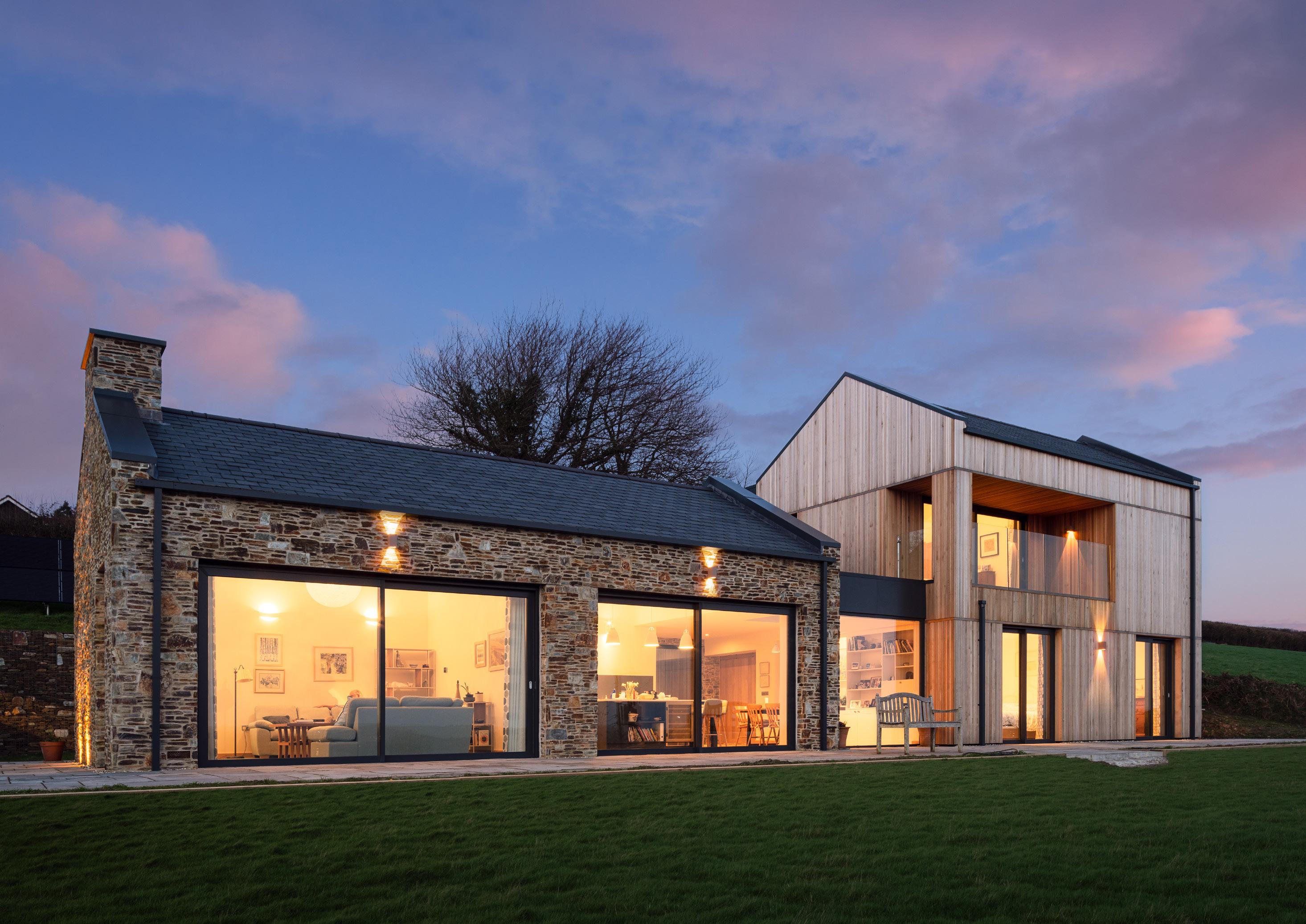
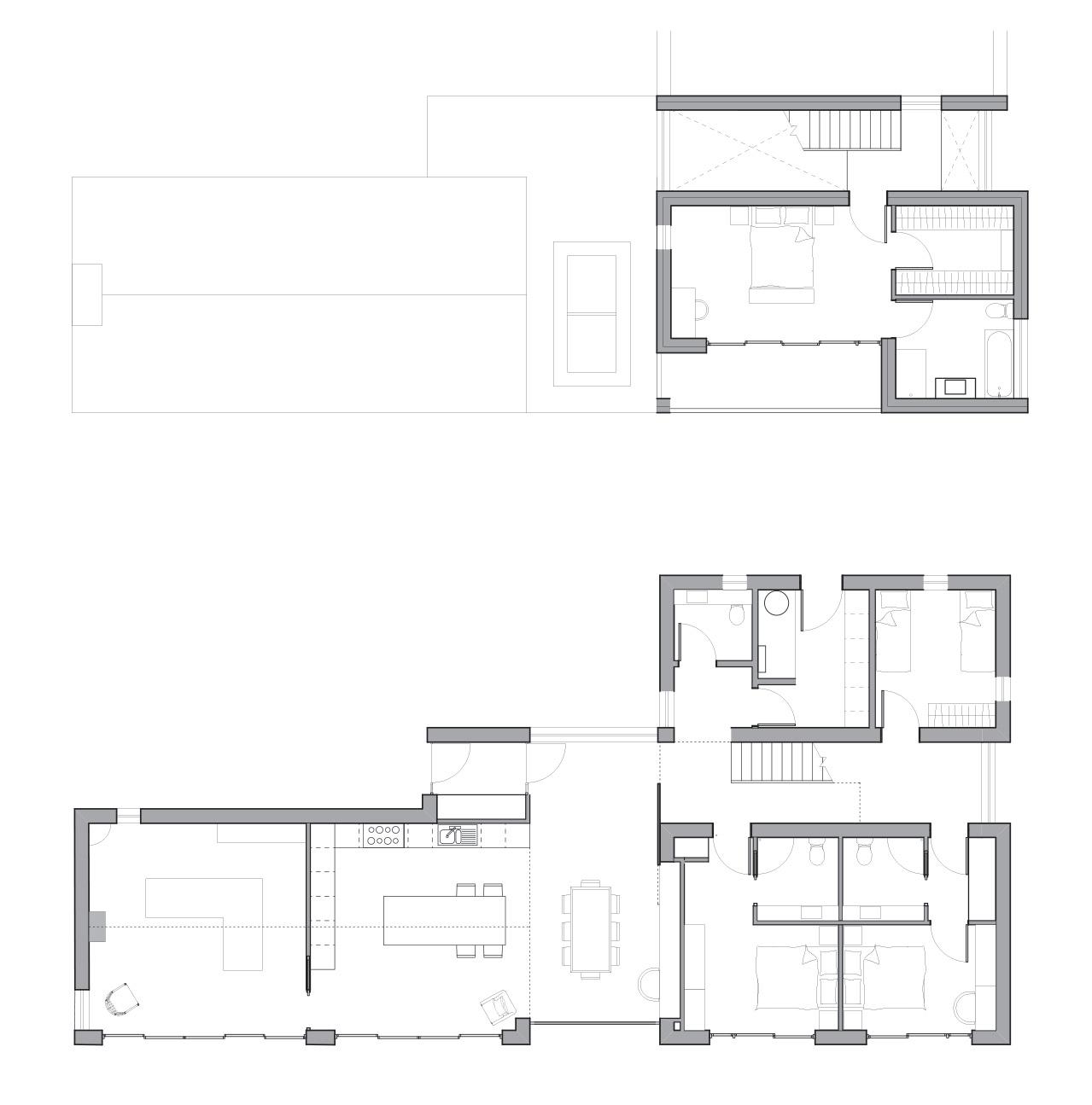
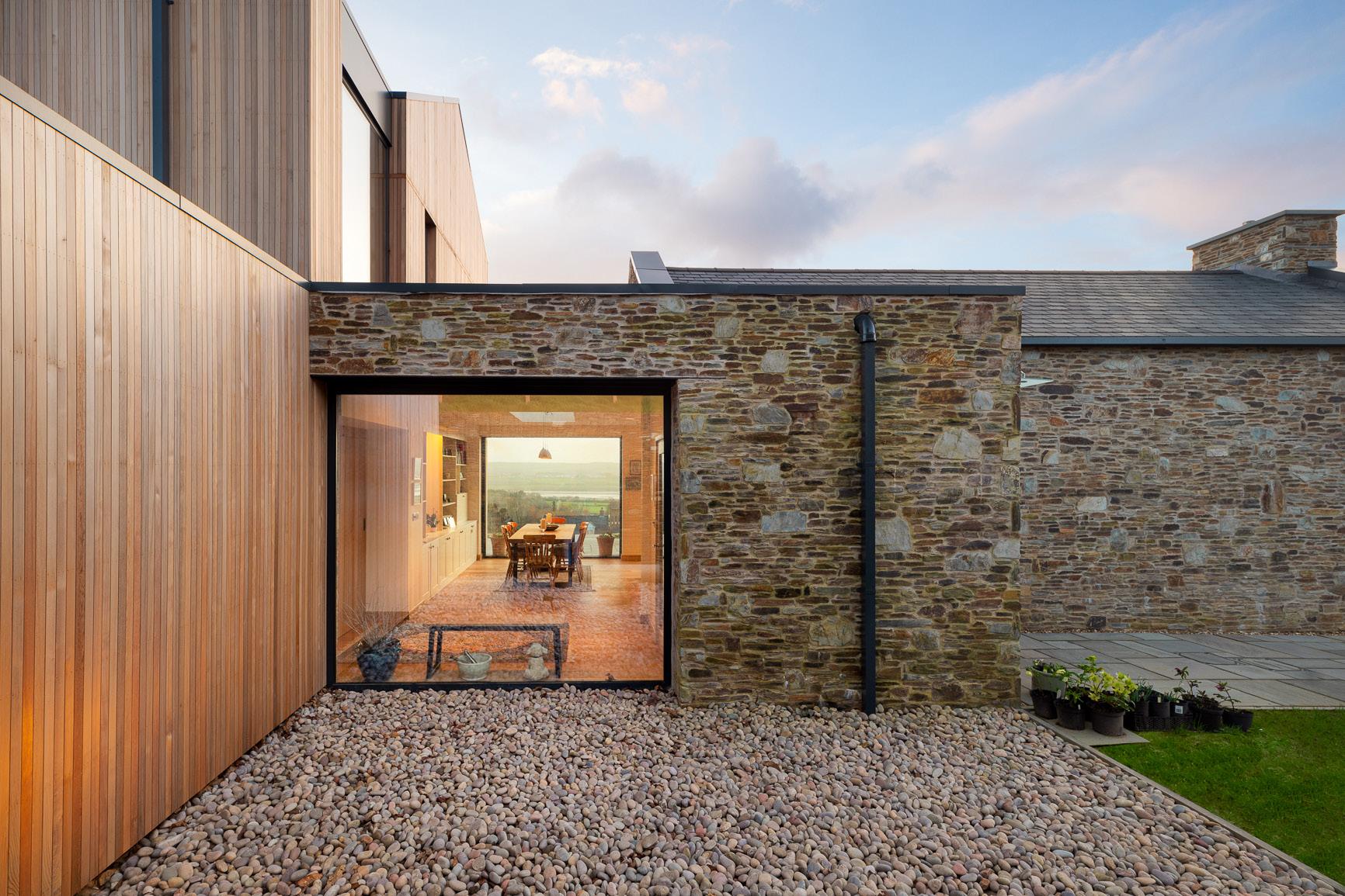
‘The Ark’ is a bespoke dwelling in Ashford, North Devon, situated to the edge of the village with panoramic views over the Taw Estuary and beyond. The form takes inspiration from a traditional Devon Longhouse, with the building oriented along the line of the topography, facing South.
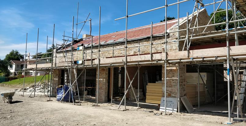
I was involved between RIBA Stages 3 & 6 on this project, working alongside the Project Architect to develop Planning and Tender Packages. I was directly involved in the construction process after the Project Architect left the Practice, dealing with the clients and contractor, resolving site queries and participating in bi-weekly site meetings.

Regional Finalist: LABC Building Excellence Awards 2020 (Best Individual New Home)


p. 92
First Floor Plan Ground Floor Plan
© Lawrence Liddy
© Lawrence Liddy
Galvanised 203x203x46 UC as S.E design and specification Webs to be fully filled with rigid insulation 15mm
8mm galvanised steel plate welded to underside of beam to support stone wall, as SE design and specification
25x38mm s/w battens shot fired to steel plate above, providing fixing for flashing
PPC aluminium flashing, RAL 7016
PPC aluminium flashing, RAL 7016 Fixed back to battens with C/S screws with heads coloured to match flashing
38x50mm s/w battens to cill fixed back to chipboard floor deck Void between battens to be filled with mineral wool
EPDM sealed to VCL
Window Head & Cill Details (Originally 1:5 @ A1)
Flexible bitumen sheet cavity tray, contractor selected item
Weep holes provided in blockwork to drain cavity, spacing as manufacturers guidance
PPC aluminium flashing, RAL 7016 Drip edge to be provided at end of flashing Fixed back to plywood rip above Top edge of flashing to be laid underneath end of cavity tray
EPDM taped and sealed to underside of steel plate
Isochemie ‘ISO-BLOCO 600’ expanding sealing tape to gap between window frame and flashing to be installed in accordance with manufacturers instructions
Schuco AWS 70.HI openable aluminium window, RAL 7016 Fixed back to structure with window straps and base block as Schuco standard details
EPDM lapped and sealed to single ply membrane
PPC aluminium cill/flashing with profile matching side/head flashings RAL colour TBC Cill to be angled to allow for water runoff Timber fillet to aid drainage
Kingspan Thermabate, or similar approved insulated cavity closer, sized to suit 140mm cavity Shorter flange (nearest to internal blockwork skin) to be removed as Kingspan guidance
Slab Edge Detail (Originally 1:5 @ A1)
p. 93 Reveal Details - Windows 2 1217 Drawing Title Project Title Long Lane Ashford for: Mr and Mrs Clapp Details amended A 12/6/18 CE Structure to head of beam amended in detail 06 B 15/6/18 CE Amendments to wall build up on detail's 05 & 06 C 04/09/18 LMJ Feature wall ammended Details 05/06 updated to suit Lintel to Detail 06 updated to suit new S.E design D 18/09/18 JG Details updated to suit new glazing system E 22/01/19 JG Detail 02 and 04 updated to suit contractors comments F 06/02/19 JG -For all Lighting Information see Amos Lighting Drawings - All drawings to be read in conjunction with supporting information provided by PMA, including Construction Notes, Specifications, and Schedules as relevant 05. PLAN DETAIL IN PPC
have
match flashing window EPDM to provide airtight seal 25x38mm timber battens forming boxing around window frame, providing fixings for aluminium pressing Voids in boxing to be filled with mineral wool slabs between away (or closed external in directly grey) angle to
aluminium pressing, RAL 7016 Screw fixings to
C/S heads PPC'ed to
208mm 172mm 218mm 45mm 235mm 30mm 88mm 190mm 253mm 45mm
150mm +36 AFFL
AFFL
+1995
Client selected 30mm paving slabs with permeable joints laid on 50mm sharp sand bed Multitrack NW8 geotextile membrane 90mm Kingspan Styrozone N300R XPS closed cell insulation below DPC level Plasterboard with 110mm service zone behind to allow for recessed blind enclosure DPM to be continued down outer face of blockwork Concrete strip foundations as S.E specification Below ground blockwork to have a minimum compressive strength of 7N/mm2 as S.E specification min 150mm Bottom of cavity to be filled with lean mix concrete Weep holes formed in stonework to allow for water egress Distribution to manufacturers guidance SureCav 50 Novia Black U resistant breather membrane 50mm Kingspan Kooltherm K112 Framing Board Breather membrane lapped and fully bonded to cavity tray in strict accordance with manufacturers details and written instructions with minimum overlap of 150mm Novia 1000 VCL VCL lapped and fully bonded to DPM in strict accordance with manufacturers details and written instructions with minimum overlap of 150mm 140x50mm timber sole plate fixed to blockwork below Visqueen Zedex Bitumen DPC under cavity tray Flexible bitumen sheet cavity tray, contractor specified item 69x18mm hardwood skirting board painted white 500 gauge seperation layercontractor specified item 1200 gauge DPM contractor specified item 14mm UFHS pipes fitted in NuHeat “ClipTrack” or similar approved UFHS to be designed and installed by specialist subcontractor 120mm Kingspan Kooltherm K103 rigid insulation board 150mm in-situ cast reinforced concrete slab RC28/35 with 1 layer A193 mesh to bottom of slab to S.E specification 110mm Ancon Statifix-Thor Helical Timber Tie Ancon Statifix RT2 cavity wall tie with insulation clip 198mm 600mm 450mm Insulite medium density blockwork compressive strength 7.3N/mm2

p. 94 CE Feature 1:20 @ A1 14.02.2018 Scale Drawn By Date Drawing Title Project Title Change steel A 04/09/18 Spider replaced B 17/09/18 Staircase specialist's C 08/10/18 Foundation D 14/01/19 Drawing redesign E 10/04/19 SERIES KEY: Series 10 GA Series 11: GA Series 12 GA Series 14 Building Series 21 Floor Series 22 Wall Series 23 Roof Series 24 External Series 25 Door/Window Details Series 30 Feature Series 33: Fireplace Series 34 Internal Series 35 Feature Series 36: Joinery Series 40 Electrical/Lighting -For all Structural Sizes/Connections Consultants -For all Lighting Lighting Drawings - All drawings supporting information including Construction Specifications STAIR SECTION 1:20 STAIR ELEVATION 1:20 1000mm 17.5mm toughened glass balustrade fixed back to staircase with stainless steel point fixings Glass to be pre-drilled with fixing holes during fabrication All to specialists design Top of oak handrail to landing to be set 1000mm above flooring line, position of fixing hole for handrail support by specialist subcontractor Point fixing supporting handrail to align with point fixings supporting glass below Pitch line of stairs Staircase handrail omitted for clarity Fixing height as specialists design Dotted line marks line of glass balustrade behind cut plane forms section of staircase guarding Refer to specialists drawings for details Foundations and below ground blockwork as S.E design and details Floor buildup as F004 Refer to PMA drawing 1217_T_21.01 for details Stair bolted to top of blockwork Fixing to subcontractors design STAIR BASE DETAIL 1:10 SHS stringer bolted to Steel I-Beam Fixing to specialist sub contractor design Timber flooring returned to edge of landing depth to match finalised stair tread thickness 10mm pre-formed aluminium channel between timber lip and plasterboard to form shadowgap STAIR HEAD DETAIL 1:10 Plasterboard returned to fascia 1000mm 17.5mm toughened glass balustrade fixed back to staircase with stainless steel point fixings Glass to be pre-drilled with fixing holes during fabrication All to specialists design Top of oak handrail to landing to be set 1000mm above flooring line position of fixing hole for handrail support by specialist subcontractor Point fixing supporting handrail to align with point fixings supporting glass below Pitch line of stairs Staircase handrail omitted for clarity Fixing height as specialists design Dotted line marks line of glass balustrade behind cut plane forms section of staircase guarding Refer to specialists drawings for details Foundations and below ground blockwork as S.E design and buildup as F004 Refer to drawing 1217_T_21.01 for bolted to top of blockwork subcontractors design floor to be fitted and cut stair stringers STAIR BASE DETAIL 1:10 laid over top of blockwork SHS stringer bolted to Steel I-Beam Fixing to specialist sub contractor design Timber flooring returned to edge of landing depth to match finalised stair tread thickness 10mm pre-formed aluminium channel between timber lip and plasterboard to form shadowgap STAIR HEAD DETAIL 1:10 Plasterboard returned to fascia 15mm engineered oak flooring TBC Stair Head Detail (Originally 1:10 @ A1) Stair Elevation (Originally 1:10 @ A1)
© Lawrence Liddy





p. 95

N.B: Visualisation produced prior to Value Engineering works
Riverside Community Centre
New Library, Council Offices and Community Hall (PMA)
Location: Bovey Tracey, UK
Sector: Public
Year: 2016 - 2022
Status: Completed
The project proposed a new Community Centre within Bovey Tracey; collating the town library, tourist information centre, and the Town Clerk’s offices into a single building. The design took inspiration from the industrial background of Bovey Tracey, and proposed an offset sawtooth roof form over a large multi-purpose hall, with the ancillary spaces encasing the sides and rear.
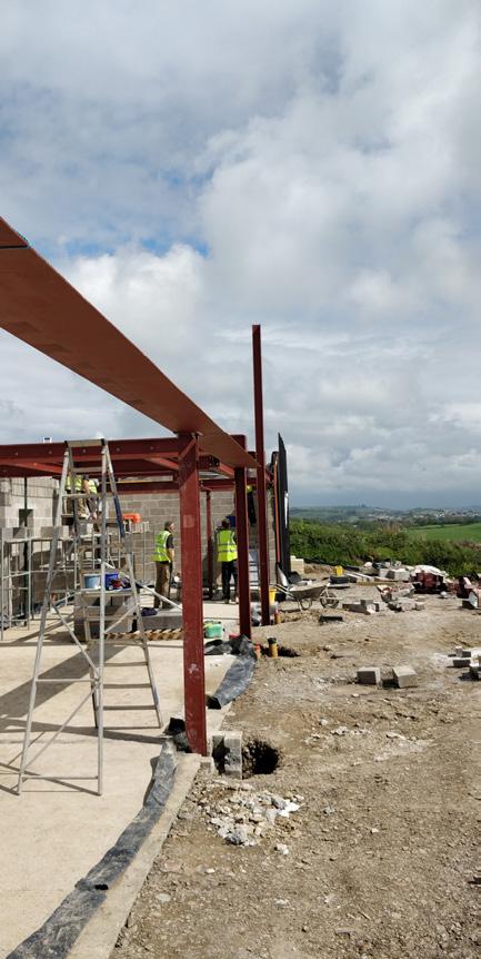
This project passed through several stages of Value Engineering before reaching site, to bring the scheme back within the Client’s budget. This resulted in numerous changes visible in the drawings and photos shown on the following pages.
I was involved on this project between RIBA Stages 3 & 5, working with the Project Architect to develop various drawing packages and assist in Contract Administration on site.


Winner: RICS UK Awards 2022 - Best Public Sector Project, South West Region
Project featured in the Architect’s Journal
p. 97
p. 98 01. RIDGE DETAIL Angled clay red ridge tile wet laid in sand cement mortar Timber fillet shot fired to top of UB acting as bearing plate for metal deck above 3 Top of steel deck cut to give square/ perpendicular edge to tray Void formed at ridge to be filled with acoustic insulation continued from troughs with VCL and rigid insulation laid over Steel UB to ridge as S.E design details and specification (GL4985mm /GL) 4985mm(GL/GL) Natural slate 600x300 with 100mm min head lap 25x50mm tanalised timber battens screw fixed to tanalised timber counter batten 25x50mm counter battens screwed to Tata Accoustic RoofDek profile through insulation Slate roof clips along eaves edge as per S.E specification and recomendation Hambleside Danelaw Universal Over Fascia Vent 36x48mm Single ply membrane fully adhered to plywood sheathing forming upstand and continued under eaves as shown Breather membrane to lap over and seal to single ply membrane under roof finish in accordance with manufacturers details and recommendations Void between steel beam and stud parapet wall to be filled with rigid insulation Roof buildup as R001 refer to PMA drawing 1690_T_23.00 for details 435mm (GL to Face of Bracket) 04 NORTH EAVES DETAIL Hambleside Danelaw Universal Over Fascia Vent 36x48mm Galvanised steel bracket supporting fascia as S.E design details and specification Bracket folded back at head to form tilting fillet Breather membrane dressed over bracket and into gutter Box profile metal gutter PPC RAL 7016 Fixed to plywood as manufacturers details and instructions 100mm 7N/mm2 concrete blockwork to S.E design and specification Timber fillet shot fired to top of steel acting as wall plate for roof deck above Line of roof deck profile behind Structural steelwork to eaves to S.E design details and specification Webs of steel to be packed with rigid insulation 100mm Thermalite 'Aircrete Hi-Strength' loadbearing concrete blockwork as S.E specification Blockwork head restraint to steel to be as S.E details and specification 120mm coursed stonework tied into stone wall with Ancon 'YPB' stone ties or equivalent approved to S.E specification spacing as manufacturers recommendations Face of stone wall shown flat for clarity VCL to be taped to head of steel to provide continuity to airtightness line in accordance with manufacturers details and recommendations 50x50x6 steel angle fixed back to roof deck to support galvanised steel bracket fixings as S.E design and specification Provide Tyvek Butyl Tape or equivalent approved under fixings between bracket and VCL to provide airtight seal to penetrations through VCL Approx 30mm tolerance gap left between stone and back of fascia Void to be filled with Tremco Illbruck 'Compriband TP600' or equivalent approved expanding sealing tape black coloured to provide weatherproof seal to void 1 30mm Roof buildup as R002 refer to PMA drawing 1690_T_23.00 for details 125mm 18mm WBP plywood forming stepped profile to eaves as shown Plywood to be painted RAL 7016 (to match aluminium colour) fixed back to folded steel bracket behind 250mm 55mm 235mm (GL to Btm Edge of Deck) 275mm (GL4985mm /GL) Plasterboard with skim finish at high level to inner face of steels 10mm black coloured C channel trim forming shadow gap to joint between plaster and plasterboard Trim to be continuous to perimeter of main hall Top of Stonework to Eaves +32.425 (3225mm AFFL) 02. FLANK VERGE DETAIL 18mm WBP plywood forming stepped profile to eaves as shown Plywood to be painted RAL 7016 (to match aluminium colour) fixed back to roofing battens with hidden fixings 'Kytun T1' aluminium dry verge pressing or equivalent approved 25mm deep to suit 8mm 'Riverstone' slate powder coated to RAL 7016 Pressing to be fixed to roofing battens prior to installation of slates as manufacturers recommendations Install pressing with drip detail proud of plywood fascia 7N/mm2 concrete blockwork to S.E design and specification to outer leaf Timber frame wall buildup at high level as Wall Type EX005 refer to PMA Drawing 1690_T_22.00 for details A 175mm (GL to Edge of Deck) Edge of VCL taped and sealed to head of steel beam with sheet left loose then lapped and sealed with VCL within roof construction after installation of roof deck to ensure continuity to airtightness layer 300x600mm 'Riverstone' hung slate to gable ends Raked steel beam to gables to S.E design details and specification Pack outer web of steel beam with rigid insulation as shown 460mm (GL to Edge of Pressing) 125mm 235mm Breather membrane dressed down face of blockwork and fixed behind vertical battens 100x50mm tanalised s/w timbers forming gable ladder to verge Tremco Illbruck 'Compriband TP600' or equivalent approved expanding sealing tape between plywood and top of hung slate 400mm (GL to End of Ladder) 122mm 38mm 145mm 30Degrees 145mm 25mm 68mm 05 HIGH LEVEL GABLE CLADDING CILL DETAIL (WEST ELEVATION) Timber frame wall buildup at high level as Wall Type EX005 refer to PMA Drawing 1690_T_22.00 for details 300x600mm 'Riverstone' hung slate to gable ends 7N/mm2 concrete blockwork to S.E design and specification to outer leaf 120mm coursed stonework below eaves level face of stone wall shown flat for clarity Stonework to be tied to blockwork wall behind with wall ties to S.E design and specification Timber frame inner 'leaf' tied to blockwork outer leaf with timber frame ties to S.E design and specification PPC aluminium drip flashing to head of stonework to gables Base of flashing to align with base of plywood fascia board to eaves Flashing fixed back to blockwork as manufacturers recommendations Finish height of stonework as detail adjacent Cavity tray to project slightly from outer leaf and be dressed down over head of drip flashing to prevent water ingress behind flashing Wet plaster finish to internal walls 10mm basecoat with 2mm skim finishing coat To recieve paint finishes to client specification Inner blockwork leaf restrained to steel beam above as S.E details and specification Airtightness tape taped to steel and blockwork to ensure continuity of airtight line Tape to include fleece backing and be suitable for recieving plastered finish over Horizontal steel beam to S.E design details and specification VCL taped to upper flange of steel beam Timber studs shot fired into webs of steel to provide fixings for plasterboard finish Line of roof deck at eaves shown greyed 10mm black coloured C channel trim forming shadow gap to joint between plaster and plasterboard Trim to be continuous to perimeter of main hall 75mm Wet plaster finish to internal walls 10mm basecoat with 2mm skim finishing coat To recieve paint finishes to client specification Inner blockwork leaf restrained to steel beam above as S.E details and specification Airtightness tape taped to steel and blockwork to ensure continuity of airtight line Tape to include fleece backing and be suitable for recieving plastered finish over Horizontal steel beam to S.E design details and specification VCL taped to upper flange of steel beam Timber studs shot fired into webs of steel to provide fixings for plasterboard finish Line of roof deck at eaves shown greyed 10mm black coloured C channel trim forming shadow gap to joint between plaster and plasterboard Trim to be continuous to perimeter of main hall FFL Top of Parapet Top of Struct Floor Suspended Ceiling -240 +0 +2400 +3300 RG20 Office RG11 Hallway RG07 Kids Area RG03 Library 01. GA SECTION A-A PPC aluminium coping to top of parapet RAL 7016 Fully adhered single ply membrane flat roof at 1:60 falls towards drainage gulleys RAL 7016 to match coping Joists angled to falls to provide drainage for flat roof Firrings used where shown on S.E drawings Surface water from South facing roof slope to drain onto flat roof For all below ground information refer to S.E drawings and specification Box profile metal gutter PPC RAL 7016 Lintels over window/door openings to be as S.E design and specification Slate natural roof finish Underside of metal roof exposed with pre-finished surface in white Planted soft landscaping to perimeter of building Geotextile membrane below topsoil layer Smart Systems or Equivalent Approved window system powder coated to RAL 7016 Aluminium pressing to perimeter of windows in stone wall powder coated to match windows 2873mm 2943mm 2951mm 2980mm FFL Top of Parapet Top of Struct Floor Suspended Ceiling -240 +0 +2400 +3300 RG09 Town Council Meeting Room RG03 Library stepped plywood verge/eaves details natural slate roof finish Larch timber cladding with 5mm penny gaps angled clay red ridge tiles Refer to Drawing 1690_T_30.08 for details of acoustic walls at high level WINDOW IN RENDERED WALL (TYPE EX002) WINDOW IN STONE WALL (TYPE EX001) CORNER WINDOW IN STONE WALL (TYPE EX001) Bar: 1:5 @ A1 0.5m 0.1 0.2 0.3 0.4 EX002 see PMA drawing finishes 10mm basecoat Render returned into reveal and terminated with render stop bead 10mm compressible weather seal to perimeter of window frame Join between plasterboard and window frame to be sealed with white mastic 12.5mm plasterboard with 3mm skim finish Smart Systems or Equivalent Approved aluminium window fixed with metal brackets back to blockwork as manufacturers details and instructions Kingspan 'ThermaBate' or similar approved insulated cavity closer sized to suit 150mm cavity Scrim tape to be used at join between plaster basecoat and plasterboard priro to finishing coats/skims being applied Tremco-Illbruck 'ME500' internal airtightness tape or similar approved fixed to both inner face of window frame and inner face of blockwork to seal VCL strip and ensure airtightness Tape to include fleece backing where taped to blockwork to give key for plaster finish over 01 REVEAL DETAIL 44mm 50mm 350mm cavity wall tie with spacing to manufacturers Wall buildup as EX002 see PMA drawing 1690_T_22.000 Flexible bitumen sheet cavity tray Smart Systems or Equivalent Approved aluminium window Catnic CG 150/100 insulated lintel to .E design details and specification Drip bead Render returned into window head Weep holes to be provided in blockwork and render spacing as manufacturers recommendations plasterboard and window frame with white mastic plasterboard with 3mm skim finish to be used at join between plaster plasterboard priro to finishing being applied 'ME500' internal airtightness approved fixed to both inner frame and inner face of seal VCL strip and ensure to be fleece backed where blockwork to give key for plaster Compressible weather seal to perimeter of window frame Wall buildup as EX002 see PMA drawing 1690_T_22.00 plasterboard with 3mm skim finish 'ThermaBate' or similar approved closer sized to suit 150mm be used at join between plaster plasterboard priro to finishing being applied 'ME500' internal airtightness approved fixed to both inner frame and inner face of seal VCL strip and ensure to be fleece backed where blockwork to give key for plaster cill board sized to suit with 25mm projection match skirtings and architraves Render stop bead Smart Systems or Equivalent Approved aluminium window sat PPC aluminium cill Compressible weather seal between window frame and render as window manufacturers instructions 02 HEAD/CILL DETAIL Ancon 'Statifix RT2' cavity wall tie with insulation clip at 450mm vertical centres 200mm deep PPC aluminium cill to Smart Systems details RAL 7016 batten fixed to u/s of lintel to carry Battens to be fixed within reveal window fixing brackets Wall buildup as EX001 see PMA drawing 1690_T_22.00 12mm wet plaster finishes 10mm basecoat with 2mm top coat 9mm WBP plywood board fixed back to blockwork/stone Compressible weather seal to perimeter of window frame Join between plasterboard and window frame to be sealed with white mastic 12.5mm plasterboard with 3mm skim finish Smart Systems or Equivalent Approved aluminium window fixed with metal brackets back to blockwork as manufacturers details and instructions Kingspan 'ThermaBate' or similar approved insulated cavity closer sized to suit 180mm cavity Scrim tape to be used at join between plaster basecoat and plasterboard prior to finishing coats/skims being applied Tremco-Illbruck 'ME500' internal airtightness tape or similar approved fixed to both inner face of window frame and inner face of blockwork to seal VCL strip and ensure airtightness Tape to include fleece backing where taped to blockwork to give key for plaster finish over 03 REVEAL DETAIL PPC aluminum flashing/pressing to window reveal fixed back to plywood with C/S fixings Flashing to align with outer edge of cill below Tremco Illbruck 'Compriband TP600' or equivalent approved expanding sealing tape to perimeter of gap behind pressing 80mm 380mm 55mm 215mm 30mm 35mm Ancon 'Statifix RT2' cavity wall tie with insulation clip horizontal spacing as manufacturers recommendations Ancon 'SPB Frame Cramp' securing stonework to blockwork horizontal spacing to manufacturers recommendations 45mm 25x38mm timber battens fixed within reveal to carry plasterboard Battens fixed horizontally within reveal between fixing straps with vertical batten to fix corner of plasterboard Wall buildup as EX001 see PMA drawing 1690_T_22.000 Flexible bitumen sheet cavity tray Smart Systems or Equivalent Approved aluminium window Steel lintels to S.E design details and specification PPC aluminium flashing/pressing to perimeter of window coloured RAL 7016 fixed back to battens within reveal with C/S fixings Top of flashing to be angled to allow for water runoff Gap between flashing and stonework to be mastic sealed Outer edge of flashing to align with outer edge of cill below Weep holes to be provided in blockwork and stonework spacing as manufacturers recommendations Join between plasterboard and window frame to be sealed with white mastic 12.5mm plasterboard with 3mm skim finish to window head Scrim tape to be used at join between plaster basecoat and plasterboard priro to finishing coats/skims being applied Tremco-Illbruck 'ME500' internal airtightness tape or similar approved fixed to both inner face of window frame and inner face of blockwork to seal VCL strip and ensure airtightness Tape to include fleece backing where taped to blockwork to give key for plaster finish over Compressible weather seal to perimeter of window frame 30x38mm tanalised s/w timber battens shot fired back to lintels above as required to fix flashing 45mm Wall buildup as EX001 see PMA drawing 1690_T_22.00 12.5mm plasterboard with 3mm skim finish Kingspan 'ThermaBate' or similar approved insulated cavity closer sized to suit 180mm cavity Scrim tape to be used at join between plaster basecoat and plasterboard prior to finishing coats/skims being applied Tremco-Illbruck 'ME500' internal airtightness tape or similar approved fixed to both inner face of window frame and inner face of blockwork to seal VCL strip and ensure airtightness Tape to include fleece backing where taped to blockwork to give key for plaster finish over 25mm softwood cill board sized to suit required depth with 25mm projection finished to match skirtings and architraves Smart Systems or Equivalent Approved aluminium window sat on PPC aluminium cill Compressible weather seal to perimeter of window frame 300mm deep PPC aluminium cill to Smart Systems details RAL 7016 04 HEAD/CILL DETAIL 50mm 45mm Ancon 'Statifix RT2' cavity wall tie with insulation clip at 450mm vertical centres Ancon 'SPB Frame Cramp' securing stonework to blockwork at 450mm vertical centres 275mm 25x38mm batten fixed to u/s of lintel to carry plasterboard Battens fixed within reveal between window fixing brackets 30mm 215mm 5mm Wall buildup as EX001 see PMA drawing 1690_T_22.00 12mm wet plaster finishes 10mm basecoat with 2mm top coat 9mm WBP plywood board fixed back to blockwork/stone Compressible weather seal to perimeter of window frame Join between plasterboard and window frame to be sealed with white mastic 12.5mm plasterboard with 3mm skim finish Smart Systems or Equivalent Approved aluminium window fixed with metal brackets back to blockwork as manufacturers details and instructions Kingspan 'ThermaBate' or similar approved insulated cavity closer sized to suit 100mm cavity between steel and blockwork outer leaf Tremco-Illbruck 'ME500' internal airtightness tape or similar approved fixed to both inner face of window frame and steel to seal VCL and ensure airtightness 05 REVEAL DETAIL PPC aluminum flashing/pressing to window reveal fixed back to plywood with C/S fixings Flashing to align with outer edge of cill below 80mm 380mm 55mm 215mm 30mm 35mm Ancon 'Statifix RT2' cavity wall tie with insulation clip horizontal spacing as manufacturers recommendations Ancon 'SPB Frame Cramp' securing stonework to blockwork horizontal spacing to manufacturers recommendations Tremco-Illbruck 'ME500' internal airtightness tape or similar approved fixed to both face of steel and inner face of blockwork to ensure airtightness Tape to include fleece backing where taped to blockwork to give key for plaster finish over 38x50mm s/w vertical battens fixed back to blockwork 45mm Tremco Illbruck 'Compriband TP600' or equivalent approved expanding sealing tape to perimeter of gap behind pressing 25x38mm timber battens fixed within reveal to carry plasterboard Battens fixed horizontally within reveal between fixing straps with vertical batten to fix corner of plasterboard 230mm External leaf and stone finish as wall buildup as EX001 see PMA drawing 1690_T_22.000 Flexible bitumen sheet cavity tray Smart Systems or Equivalent Approved aluminium window Steel lintels to be as S.E design details and specification Base of 150x90 angle supporting stonework to be offset down by 7mm and FPFW to RHS as S.E details PPC aluminium flashing/pressing to head of window RAL 7016 Fixed back to battens with C/S fixings Top of flashing to be angled to allow for water runoff Gap between flashing and stonework to be mastic sealed Outer edge of flashing to align with outer edge of cill below Weep holes to be provided in blockwork and stonework spacing as manufacturers recommendations Join between plasterboard and window frame to be sealed with white mastic 12.5mm plasterboard with 3mm skim finish to window head VCL from timber frame above returned into reveal and taped to window frame with Tremco-Illbruck 'ME500' internal airtightness tape or similar approved to ensure continuity of airtight layer Compressible weather seal between top of window frame and lintel as window manufacturers details Tanalised timber battens shot fired back to steelwork above as required to fix flashing 215mm 45mm 12.5mm plasterboard with 3mm skim finish Kingspan 'ThermaBate' or similar approved insulated cavity closer sized to suit 180mm cavity Scrim tape to be used at join between plaster basecoat and plasterboard priro to finishing coats/skims being applied Tremco-Illbruck 'ME500' internal airtightness tape or similar approved fixed to both inner face of window frame and inner face of blockwork to seal VCL strip and ensure airtightness Tape to include fleece backing where taped over blockwork to give key for plaster finish over 25mm softwood cill board sized to suit required depth with 25mm projection finished to match skirtings and architraves Smart Systems or Equivalent Approved aluminium window sat on PPC aluminium cill Compressible weather seal to perimeter of window frame 300mm deep PPC aluminium cill to Smart Systems details RAL 7016 06 HEAD/CILL DETAIL 25mm 50mm Wall buildup as EX001 see PMA drawing 1690_T_22.00 Ancon 'Statifix RT2' cavity wall tie with insulation clip at 450mm vertical centres Ancon 'SPB Frame Cramp' securing stonework to blockwork at 450mm vertical centres 48mm Timber frame internal leaf as Wall Type EX005 refer to PMA Drawing 1690_T_22.00 for details Line of projecting column encasement behind 25x38mm battens fixed to u/s of lintel to carry plasterboard Battens fixed within reveal between window fixing brackets Kingspan 'ThermaBate' or similar approved insulated cavity closer sized to suit 150mm cavity Cavity tray sealed to breather membrane 30mm 25mm 275mm 30mm 5mm 45mm GA Section (Originally 1:50 @ A1) Eaves Detail (Originally 1:5 @ A1) Reveal Detail (Originally 1:5 @ A1)
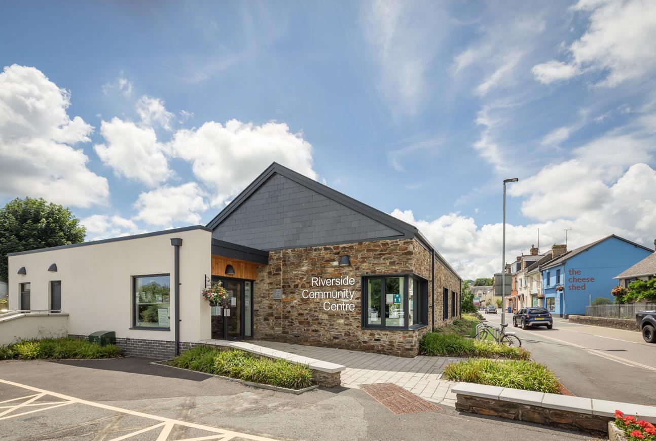


p. 99 Images by Others
07809 139943
jgoodwin9520@gmail.com
James Goodwin
University of Bath
Part I Architectural Assistant


 Visual from Taproom

 Visual in Brewing Hall


 Visualisation from ‘Innovation Hub’


