SVG BROCHURE
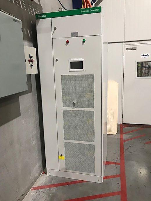
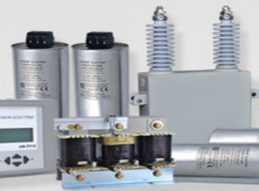
Static VAR Generators (SVG)
SiC-MOSFET Technology
Dynamic Step-less Compensation
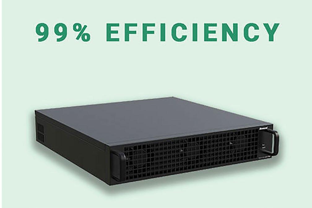
99% Efficiency
No Capacitor Banks
Wall Mounting Solutions
Load Balancing


Dynamic Step-less Compensation
99% Efficiency
No Capacitor Banks
Wall Mounting Solutions
Load Balancing
Power Factor is a measure of how effectively incoming power is used in your electrical system and is defined as the ratio of Real (working) power to Apparent (total) power.
Real Power (KW) is the power that actually powers the equipment and performs useful, productive work. It is also called Actual Power, Active Power or Working Power.
Reactive Power (KVAR) is the power required by some equipment (eg. transformers, motors and relays) to produce a magnetic field to enable real work to be done. It’s necessary to operate certain equipment but you don’t see any result for its use.
Apparent Power (KVA) is the vector sum of Real Power (KW) and Reactive Power (KVAR) and is the total power supplied through the power mains that is required to produce the relevant amount of real power for the load.
Let’s look at a simple analogy in order to better understand these terms. Let’s say you’ve ordered a glass of your favourite beer. The thirst quenching portion of your beer is represented by Real Power (KW). Unfortunately, along with your ale comes a little bit of foam that doesn’t quench your thirst, represented by Reactive Power (KVAR). The total contents of your glass (KVA) is this summation of KW (the beer) and KVAR (the foam).
The power factor is the ratio between Real Power and Apparent Power. It’s expressed as a value between -1 and 1 and can be either inductive (lagging) or capacitive (leading). If the power factor is 1, then all of the power supplied is being used for productive work and this is called ‘unity’. Real Power (KW)
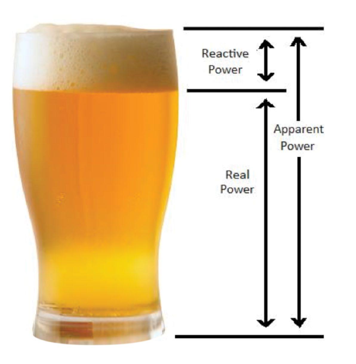
Reactive Power (KVAR)
Apparent Power (KVA) Real Power (KW)
Therefore, for a given power supply (KVA):
• The more foam you have (the higher the percentage of KVAR), the lower your ratio of KW (beer) to KVA (beer plus foam). Thus, the poorer your power factor.
• The less foam you have (the lower the percentage of KVAR), the higher your ratio of KW (beer) to KVA (beer plus foam) and the better your power factor. As your foam (or KVAR) approaches zero, your power factor approaches 1.0 (unity).
A power factor of -0.7 for example, indicates that only 70% of power supplied to your business is being used effectively and 30% is being wasted. The wasted power is the Reactive power (the foam in the previous example). Most loads are inductive in nature, which means the power factor will typically be less than unity. The further the power factor is from unity, the greater the apparent power drawn and therefore, the greater the current draw for the system.
The increased current may require an increase in the size of your transformers and installation power wiring. Increased current also results in increased heat which affects the longevity and lifespan of an electrical system. This can add a great deal of cost to the installation and may also limit the expansion of a plant.
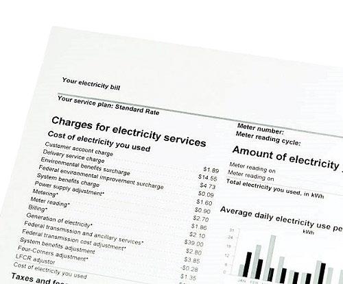
The Electricity Utilities are changing the way they are billing you. Traditionally, our electricity has been charged according to a kW (kilowatt) demand tariff which is commonly known as ‘real power’. This means that you are charged for the electricity that you actually use. The change is that you will now be charged according to a kVA (kilovolt-ampere) demand tariff which is commonly known as ‘apparent power’ (or real power plus re-active power). Every electrical facility consumes an amount of re-active power. This energy is considered ‘wasted’ as it does not perform useful work.
The changes are currently being rolled out across Australia. Most states have already changed to the new billing method and the others are following soon. So if your billing has changed to a kVA demand tariff and you have a poor power factor, you are definitely paying for that wasted power. Improving your power factor can result in considerable savings on your power bills. By installing Power Factor Correction equipment, you will be able to reduce your Peak kVA Demand Tariff and this will result in significant savings in your electricity costs.
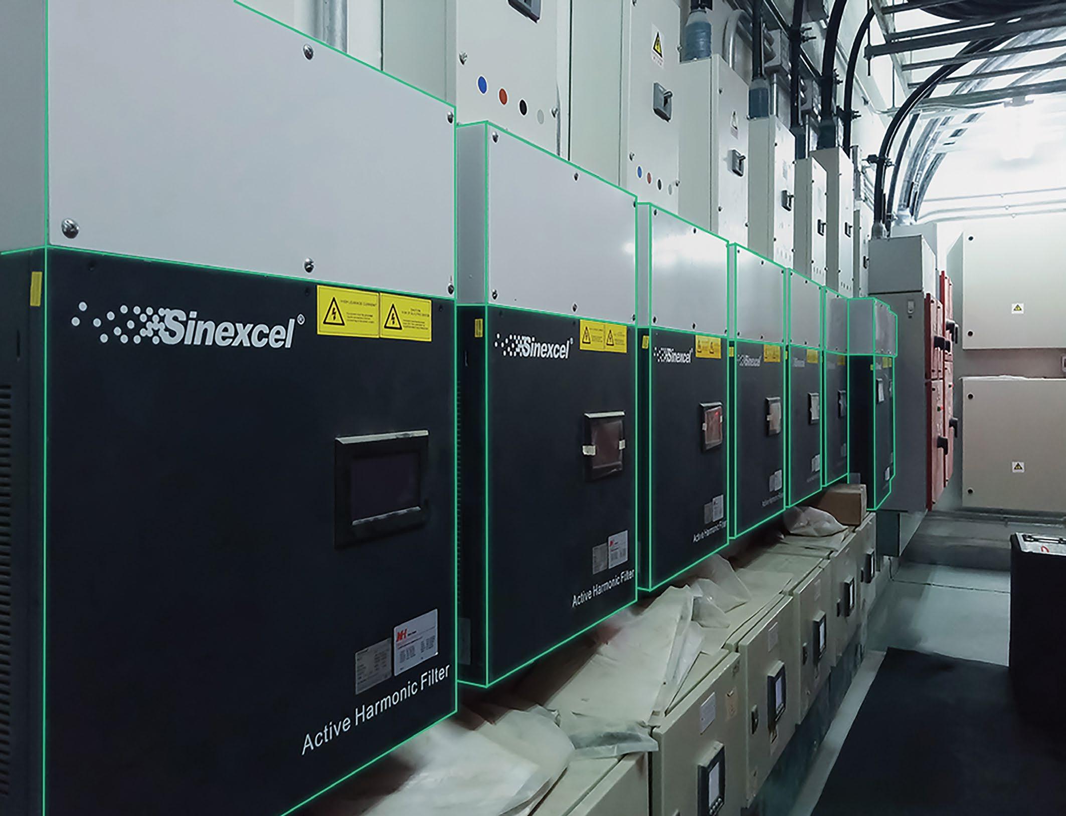
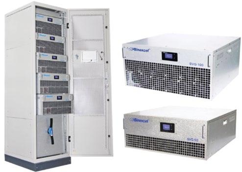
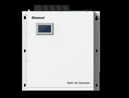
The latest generation SiC-MOSFET technology. Offers instantaneous, dynamic step-less compensation. Ideal for the challenging demands of modern electrical environments. Compact & modular configuration (including wall-mount options). Reliably operating at hundreds of sites around Australia.
30kVAr &
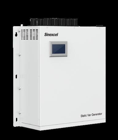
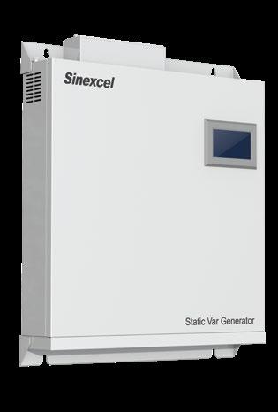
30kVAr
500W x 88D x 470H (mm)
Weight: 24kg
50kVAr
500W x 88D x 470H (mm)
Weight: 24kg
100kVAr
500W x 100D x 520H (mm)
Weight: 32kg
200kVAr
500W x 220D x 646H (mm)
Weight: 63kg
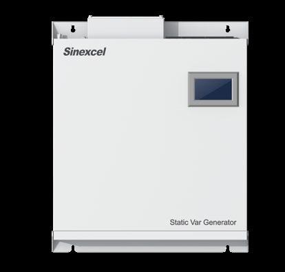
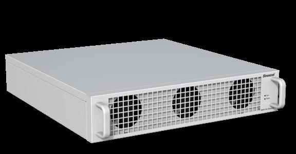
30kVAr
500W x 470D x 88H (mm)
Weight: 24kg
50kVAr
500W x 470D x 88H (mm)
Weight: 24kg
100kVAr
500W x 520D x 100H (mm)
Weight: 32kg
200kVAr
500W x 646D x 220H (mm)
Weight: 63kg
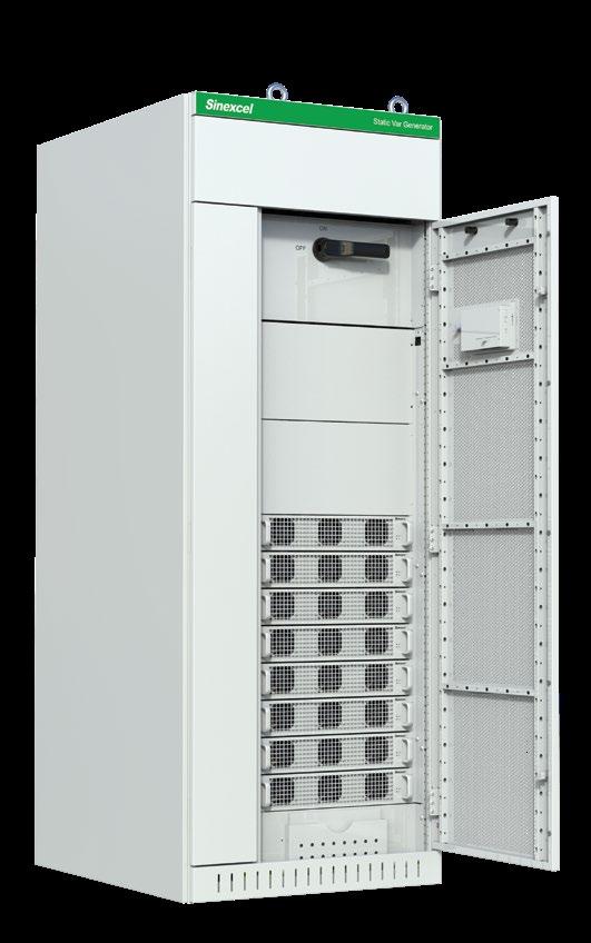
Up to 800kVAr (8 x 100kVAr)
800W x 800D x 2200H (mm)
800W x 1000D x 2200H (mm)
Up to 400kVAr (4x 100kVAr)
800W x 600D x 2200H (mm)
Up to 500kVAr (5x 100kVAr)
1000W x 600D x 2200H (mm)
Up to 600kVAr (6x 100kVAr)
1200W x 600D x 2200H (mm)
Up to 400kVAr (4x 100kVAr)
700W x 900D x 1800H (mm)
Also available in these sizes:
800W x 600D x 2000H (mm) *Flush against the wall*
1000W x 1000D x 2200H (mm)
Sinexcel are the first power factor correction manufacturer to implement Silicon Carbide Mosfet (SiC) technology. Sinexcel SVG’s (P5 series) operate at 40kHz and have the ability to operate up to 90kHz when required (current standard is 20kHz). Much less heat is produced, which has a dramatic impact on ventilation requirements and the sizing of supporting components. This in turn has resulted in extremely compact and light weight physical unit sizing which is unprecedented. 200kVAr wallmounted units weigh only 63kg and up to 800kVAr capacity is possible from a single cabinet! This is the latest in a long history of innovation which places Sinexcel as the undisputed global leader in SVG power electronics.
Considered to be the greatest ever breakthrough in power factor correction design, Sinexcel have launched the new P5 series which delivers an unprecedented peak efficiency of 99%. If achieving your Net Carbon goals is important to your project, the Sinexcel SVG is the most efficient SVG technology available. This has been achieved by the first-ever implementation of Silicon Carbide Mosfet (SiC) technology, which allows the switching frequency to be increased up to 4.5 times the present standard of 20kHz. This has a dramatic impact on efficiency – a genuine game-changer for AHF applications.
n Ultra-low Heat Loss
n High Switching Frequency
n High Withstand Voltage
n High Power Density
n High Heat Conduction Rate

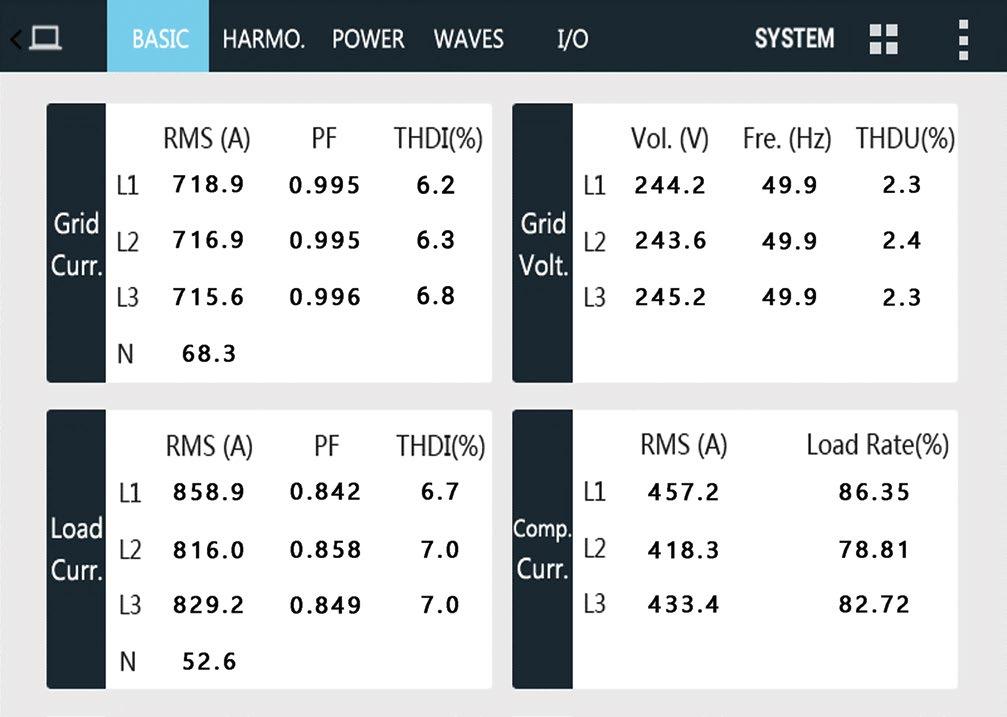
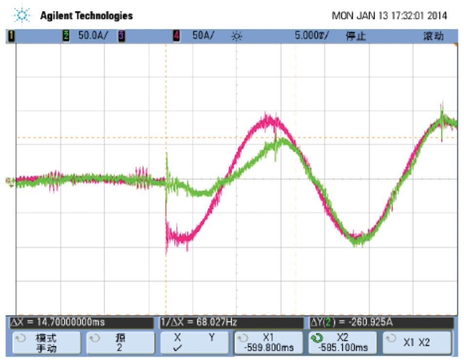
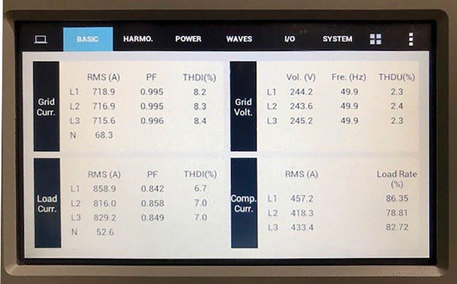
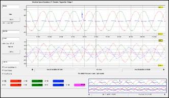
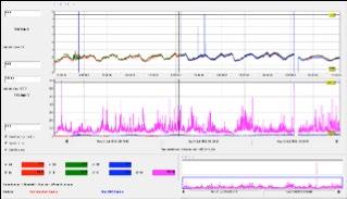
This screenshot is from a Sinexcel SVG unit operating at one of our customer locations.
Balanced Phase Currents Corrected Power Factor Phase Imbalance Poor Power Factor
Please Note:
• The Load Current information in the bottom left of the screen displays the actual load, RMS (Amps) of the site, the PF (Power Factor) and the THDI (Total Harmonic Distortion Current).
• There are 2 important factors to note here. Firstly, this site has a significant phase current imbalance. The RMS between the 3 phases ranges from 858.9A to 816A. That is a 42.9A phase current imbalance. Secondly, the PF ranges from 0.842-0.858 across the three phases which is considered poor and correction is required.
• The Grid Current information at the top left of the screen displays the corrected RMS and PF after compensation by the Sinexcel SVG. Note that the phase current imbalance has been corrected and the RMS has been reduced to 442A (approx. 17% reduction). The PF has been corrected to 0.995. This sort of performance cannot be achieved with traditional PFC systems.
• By correcting the power factor and the phase imbalance, the Sinexcel SVG presented an almost perfect load to the grid, resulting in a maximum return available when a kVA peak demand tariff is used, which significantly reduced their energy costs.
n Up to 200kVAr capability from a single wall-mounted module – can be parallel connected for unlimited capacity.
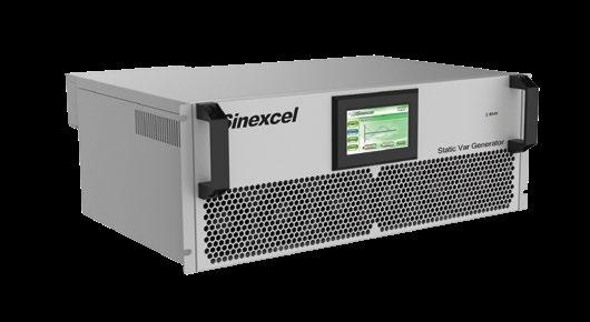
n Up to 200kVAr capability from a single rack-mounted module.
n Up to 800kVAr capability from a single cabinet solution.
Excellent power factor correction performance
• Can maintain a PF of 0.99 lagging or unity if required
Instantaneous real-time compensation
• Dynamic reaction time is less than 50µs
Corrects lagging (inductive loads) & leading (capacitive loads)
• Power factor range (-1 to +1)
Corrects load imbalance
• Can balance the phase currents to further lower the peak kVA presented to the grid.
• Wall or rack mounted modules can be parallel connected to increase capacity in a ‘Master / Master / Master’ arrangement.
• In the event that one unit shuts down, the other units remain operational.
• Measures and provides dynamic kVAr compensation throughout all three phases.
• No AC switched capacitors to be affected by resonance & harmonics in the system.
• If you already have an existing capacitor bank PFC system, you can add an SVG to improve the performance.
• If you already have an existing capacitor bank PFC system, you can add an SVG to improve the performance.
• If your billing has changed to a kVA demand tariff and you have poor power factor, you are definitely paying for electricity that you are not using.
• In such cases, the SVG will reduce your electricity bills.
• Typically, most installations achieve savings of 10% - 30%.
• No maintenance costs required, no on-going servicing or spare parts required.
• The most vulnerable and weakest links in a traditional PFC system are the switched capacitors.
• Capacitors can leak, rupture or ignite with a life expectancy of 3-7 years, depending on the environmental conditions.
• This results in high maintenance costs.
• The SVG eliminates all of these issues, resulting in greater longevity and minimal maintenance costs.
• It makes great financial sense to invest in SVG technology.
• Typically, a ROI of 15 months to 3 years is achieved.
• After this period, the site benefits from cheaper on-going electricity costs permanently.
• There are no capacitors to maintain! On-going costs are negligible.
• The SVG reduces heat on the electrical system, resulting in greater longevity and lower maintenance costs of the whole electrical system.
• With traditional capacitor based systems, when smaller steps are needed for fine adjustment, the space required for either 6.25kVAr or 50kVAr steps is the same.
• Small steps for fine adjustment also result in the system getting frequently switched, over-used and worn out.
• The SVG does not suffer from this problem.
• Designed to be a ‘plug & play’ experience for the user.
• Graphic interface offers direct control without the need for a PC.
• Backlit display is easy to operate and is password protected.
Sinexcel have introduced their latest generation range of Static Var Generators (SVGs) that incorporate many unique and innovative design features. SVGs perform as controlled current sources, thus obtaining a power factor of 0.99 lagging whilst avoiding over-compensation and under-compensation (traditional capacitor bank systems are almost perpetually chasing the load). The complete response time of the SVG is less than 5ms and the dynamic response time is less than 50µs. The SVG can track the dynamics of the load and compensate accordingly in almost real-time.
The SVG detects the load current on a real-time basis through an external CT’s and determines the reactive content of the load current. The data is analysed by an advanced algorithm program and the SVG’s controller provides a control signal to the SiC-MOSFET (semiconductor switch) via Pulse Width Modulation (PWM) to make the inverter produce the exact reverse reactive current of the corresponding load reactive current. The SVG can correct both a lagging and a leading power factor, as well as work with a traditional capacitor type PFC system to eliminate over and under compensation.
n Profiles the load and operates with a response speed of <5ms
n Dynamic reaction time is less than 50µs
n No possibility of over-compensation or under-compensation
n Only injects the kVAr that is needed in that moment
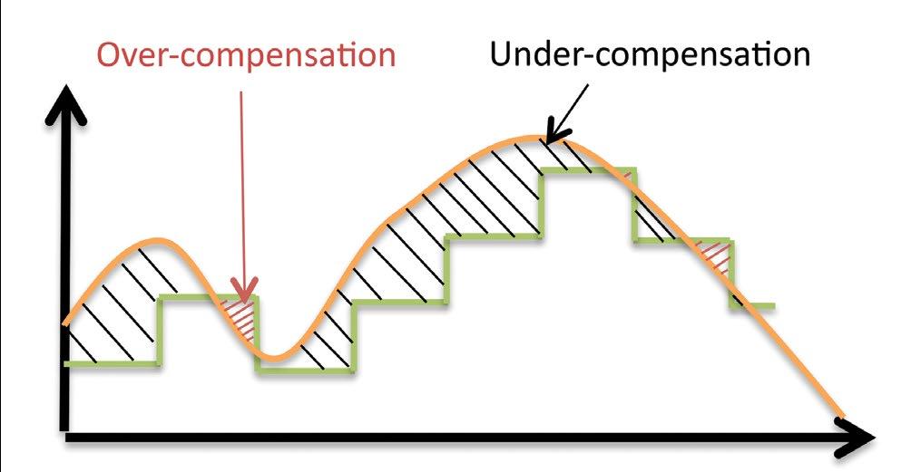
Traditional capacitor type PFC systems take 20ms-40s to respond to a change in load. Their delay combined with the stepped response performance means that they are perpetually over or under compensating.
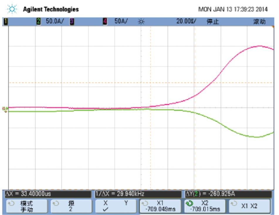
SVG Reaction Time <50µs, response time < 5ms
The Sinexcel recalculates the required load accurately and quickly. The SiC-MOSFET technology switches with high speed, quickly matching the load requirement.
n Virtually maintenance free
n Can be used with existing PFC systems
n High reliability and safety
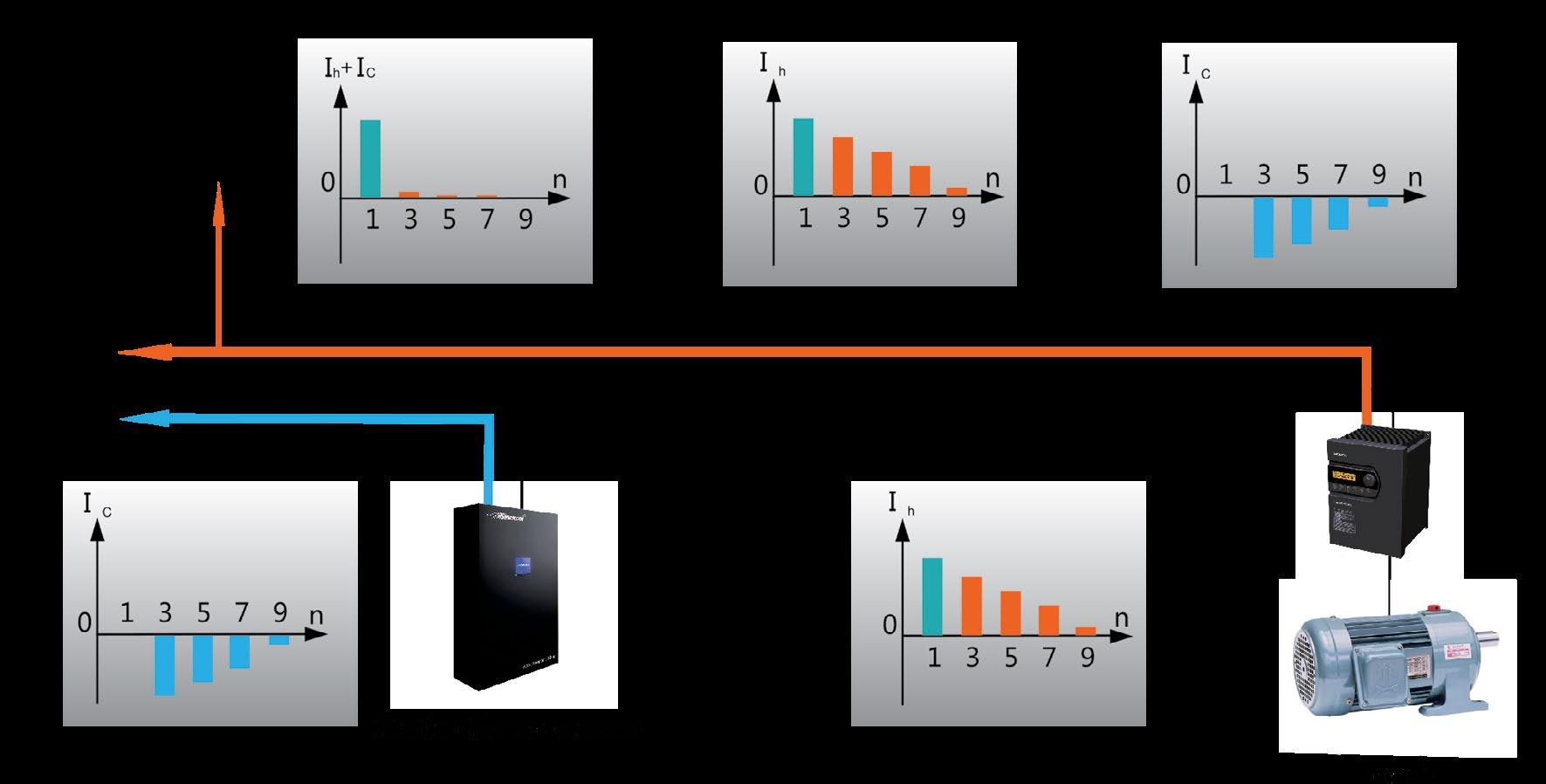
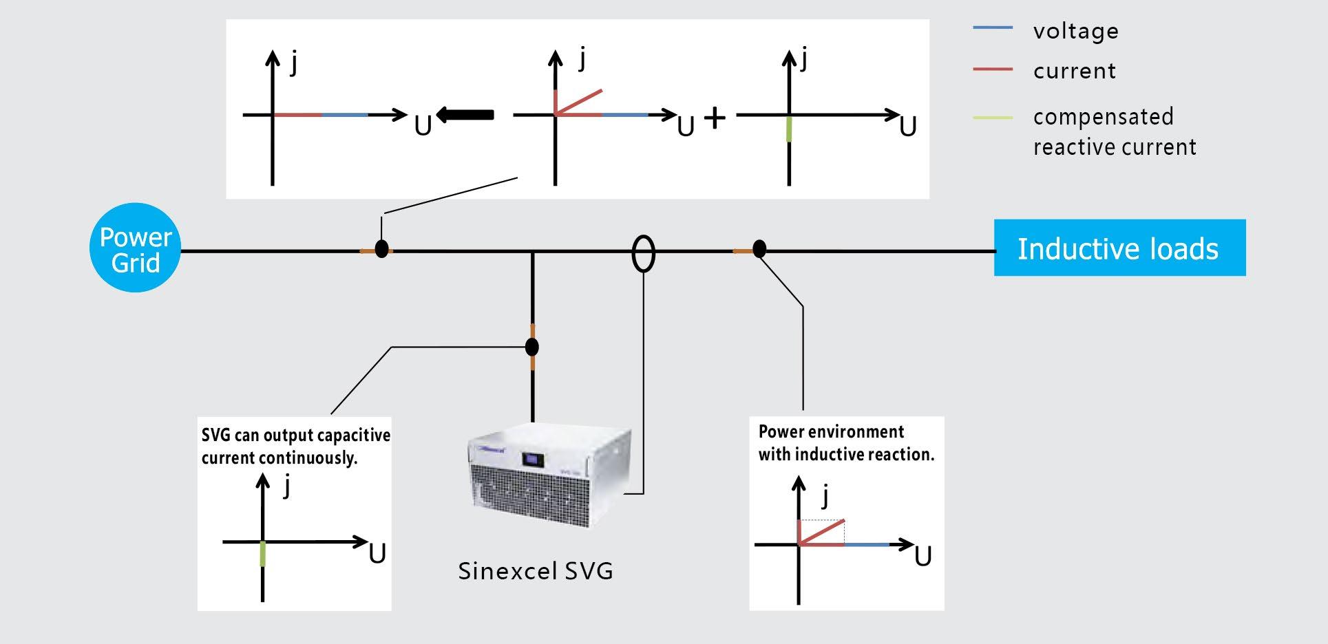
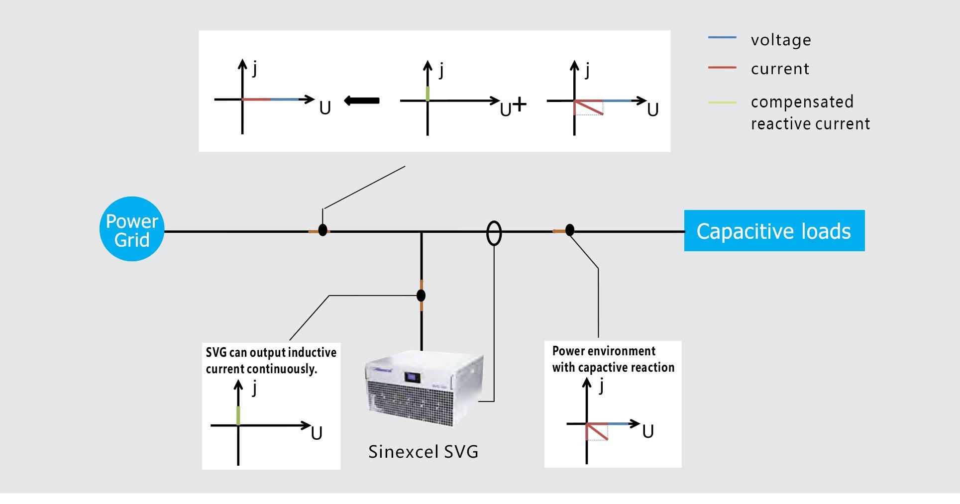
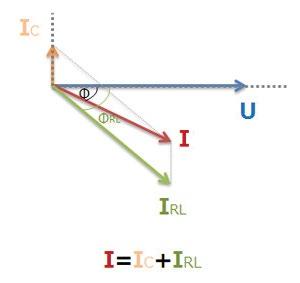
The Sinexcel SVG represents the latest generation technology in the power factor correction field. It operates by detecting the load current on a real-time basis through an external CT’s and determining the reactive content of the load current. The data is analysed and the SVG’s controller drives the internal Silicon Carbide MOSFET System by using pulse width modulation signals to make the inverter produce the exact reverse reactive current of the corresponding load reactive content. This is injected to the grid to compensate the reactive content of the load current. By adjusting the output voltage amplitude and phase angle or by directly controlling the AC side current, the SVG can absorb or generate VAr according to the load reactive power or the grid voltage level.
Sinexcel SVG compensate inductive loads
Sinexcel SVG compensate capacitive loads
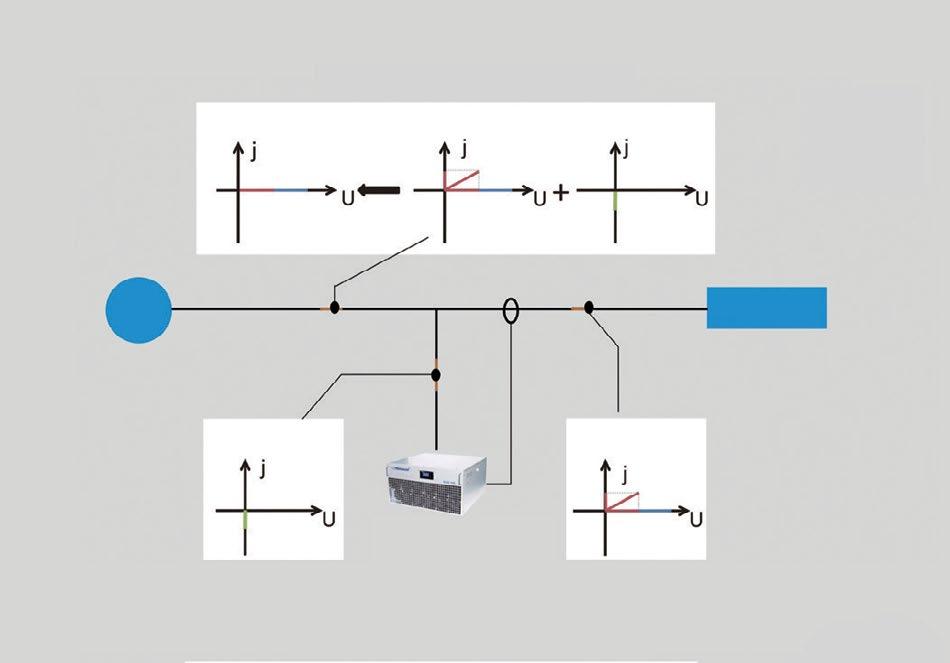
Comparison between a commonly used capacitor type system and the latest generation power factor correction technology from Sinexcel (SVG)
The system detects the load current on a real-time basis through an external CT and determines the reactive content of the load current. The data is analysed and the system’s controller switches in the required amount of reactive current in steps, depending on the amount of reactive current available to it in that moment from the capacitor bank.
Before compensation After compensation
Traditional PFC systems use capacitors in groups. Their output current is in fixed steps (50kVAr, 25kVAr, 12.5kVAr, 6.25kVAr) which usually leads to over or under-compensation.
Capacitor bank style PFC systems take at least 20ms - 40s to perform compensation depending upon whether the switching is done via a solid state switch or a contactor.
Traditional PFC systems are affected by resonance, which is detrimental to the capacitors. To lower the risk, de-tuning reactors are introduced into the circuit to lower the resonant frequency below that of the lowest harmonic in the circuit.
Capacitor bank style PFC systems can only compensate for inductive loads.
Capacitor output is subject to the voltage of the grid, so if the grid voltage is low the output of the capacitors will be low, resulting in a decline in available compensating capacity, under-compensation and possible fault conditions.
To better suit the changing dynamics of the load a traditional capacitor type PFC system needs to be oversized and to have a greater number of smaller steps to better suit the application. This increases the cost significantly.
The SVG detects the load current on a real-time basis through an external CT’s and determines the reactive content of the load current. The data is analysed and the SVG’s controller drives the internal SiC-MOSFET system by using PWM signals to make the inverter produce the exact reverse reactive current of the corresponding load reactive current.
The SVG performs as a controlled current source, thus obtaining a power factor of 0.99 lagging whilst avoiding overcompensation and under-compensation.
The complete response time of the SVG is less than 5ms and the dynamic response time is less than 50µs. The SVG can track the dynamics of the load and compensate accordingly in almost real-time.
The capacitance of the SVG does not require the installation of a de-tuning reactor. Performing as a current source and an active compensation device the SVG has been designed to not be affected by resonance.
The SVG can correct both a lagging and a leading power factor, as well as work with a traditional capacitor type PFC system to eliminate over and under compensation.
Designed with an active compensation circuit. Therefore the voltage of the grid has little influence on the compensation capacity. The output of reactive current matches the working conditions even when the voltage of the power grid is low.
The compensation capacity of the SVG is the same as the installed capacity. Therefore for a given compensation effect the capacity of the SVG may be 20% - 30% less than that of a standard capacitor type PFC System.
Located near Derrimut, Melbourne is a bottling & distribution facility of the timeless classic brand Campari. The electrical engineering team on site suspected that they had poor power factor, a fact that was confirmed once they conducted their power quality measurements. They calculated that a 350kVAr solution would be required and reached out to Fuseco for advice. The installation of a Sinexcel SVG system transformed their electrical environment.
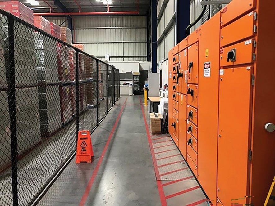
Fuseco supplied a 350kVAr Sinexcel SVG cabinet solution (SVG-350-4-4L-RL). Most of the settings are pre-programmed at Fuseco’s premises, so commissioning the unit at Campari’s facility was relatively straight forward. The LCD screen is very easy to use and set up is virtually ‘plug and play’. The Sinexcel rack-mounted modules within the cabinet can be parallel connected in a ‘Master / Master’ type arrangement, which provides the safest continuous operation. If one unit is shut down for whatever reason the remaining modules remain in operation until the alarm is attended to or the situation resolved.

The Campari bottling and distribution facility is a dynamic environment with all the usual challenges associated with growth. The electrical systems have grown with the demand however the engineering team reached a point where they knew that opportunities existed to optimise the system and achieve some significant cost savings. Once they measured their power factor performance, it was clear that the addition of a 350kVAr system would reap dividends. After consulting with the Campari management, the Fuseco team proposed a Sinexcel SVG cabinet solution to be located near the main switchboards.
The addition of the Sinexcel SVG had a very positive affect on the electrical system. If we check the screenshot of the unit’s LCD display, we can see that the power factor has improved from around 0.84 to 0.99. The current is now balanced across all three phases and has been reduced by around 100A. The operation of some solar inverters has a minimal affect on the THDI, however the electrical system is now benefiting from the improved power factor. Campari reported post-installation that they were extremely happy with the cost savings achieved and were happily reporting that their power bills were significantly reduced.
Prior to Sinexcel entering the market in 2009, Power Factor Correction installations were physically large, expensive to maintain (capacitors) and very limited in their performance.
Sinexcel revolutionised this area of power quality and continue to this day to be streaks ahead of any brand in the market.
You can trust that with Sinexcel, you are working with the people that invented this technology. This is what Sinexcel has achieved in the field of power factor correction:
1st to use IGBT switched technology.
1st to introduce ultra-compact sizing and wall-mounted solutions.
1st to introduce 3-level topology technology.
1st to introduce affordable solutions.
1st to introduce SiC-MOSFET technology.
With literally hundreds of Sinexcel SVG’s in service all over Australia, the brand has proven to be very reliable and has become the first choice for power engineers nationwide.
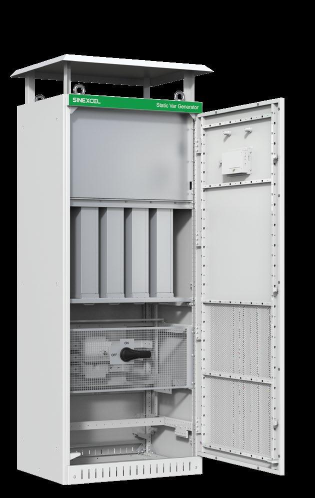
Electronic components separated from heat producing components and housed in their own sealed compartment, resulting in greater protection from the effects of heat and dust ingress.
Air inlet
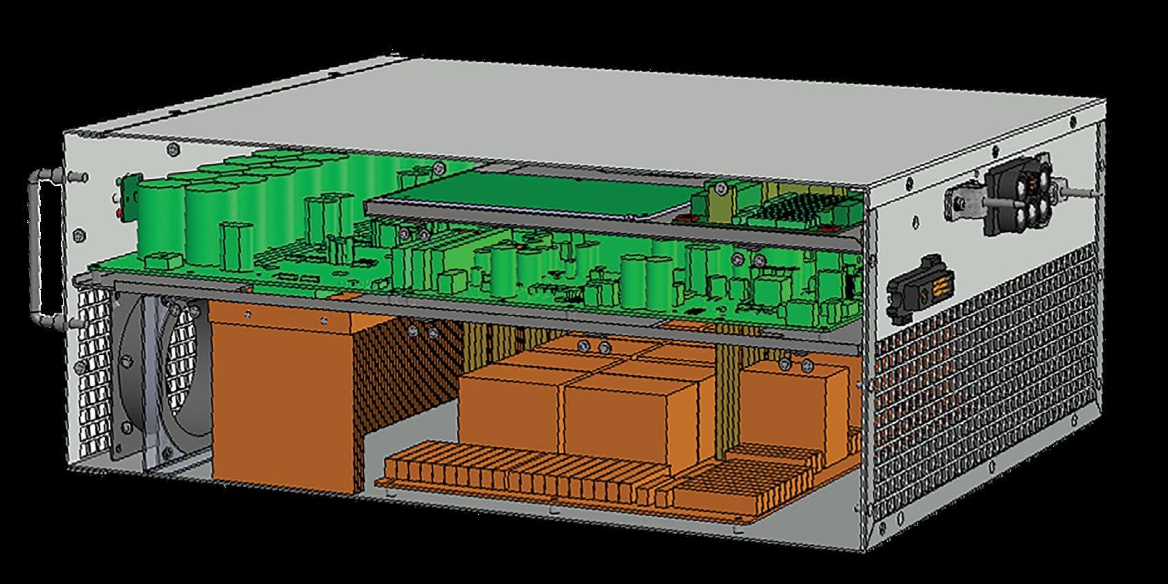
Air outlet
Heat sinks, SiC-MOSFET’s, inductors and other heat producing components housed in a separate compartment optimised for efficient ventilation and cooling.
n Internal short circuit protection
n Temperature monitoring
n Over-voltage protection
n Under-voltage protection
n Abnormal frequency protection
n Output overload protection
n CT installation detection
n Inverter bridge abnormal operation protection
n Inverter over-current protection
n Over compensation capacity
n Component capacity redundancy
n Fan fault protection
n Fuse protection
n Busbar over-voltage protection
Power Factor Correction systems have come a long way in a short space of time. Most of the evolution has focused on the switching performance of the system however in recent times, advances in technology have removed the need for switched capacitor banks, resulting significantly faster performance and smaller cabinet footprint.
A Power Quality Site appraisal is a service offered by Fuseco to our customers. A Power Quality Consultant visits your site and conducts a power quality appraisal of your electrical system.
This involves setting up sophisticated measuring equipment on site that monitors and records all of the electrical activity that is occurring within the system over a period of time. The equipment is compact, easily transportable to most locations and can be set up indoors or outdoors.
An analysis of the recorded data usually helps to reveal any harmful harmonics, voltage supply and power factor issues. Our power consultant will consider the data and present you with a power quality report, outlining the observed issues and suggesting solutions if required.
Appraisals are useful in determining electricity usage inefficiencies and identifying damaging harmonics which occur in electrical systems.
Even correctly functioning power systems require routine auditing to ensure early identification of any potential issues and proactive servicing requirements to keep power equipment operating to its full potential and the electrical environment complying to the Australian Standard AS/NZS 61000.3.6 and compatible with the IEEE519 recommendations.
A correctly functioning system could save you upwards of 30% off your power bills. In some industries and installations, that could translate to significant increases to your bottom line. By running an efficient system you also use less energy and therefore help the environment.
To discuss our site analysis service in more detail, please contact a power quality consultant at Fuseco.
The following information relates to the 30kVAr, 50kVAr, 100kVAr & 200kVAr modules. Please note that up to 900kVAr is possible in a single tier cabinet configuration.
Voltage of rated AC Input
Line 380V (690V also available)
Input Phase Voltage Range -40% to +20%
Input Frequency 50Hz auto sensing (45Hz-63Hz range)
Maximum Multiple Units Unlimited (up to 800kVAr per cabinet)
Efficiency 99%
Power Loss 1%
Network Structure 3P3W, 3P4W
CT Setting Range 50/5 - 30,000/5
Parallel Connection Yes
Topology Design 3-Level
Reaction Time <50µs
Full Response Time <5ms
Alarm & Reporting Detailed alarms and fault messages with real time stamping
Monitoring
Cable Entry
LCD Monitor/HMI centralised monitor (4.3 or 7-inch touchscreen)
Wall mounted is top connect, rack mounted is rear connect and the cabinet is top & bottom connect
Mounting Type Wall, rack or cabinet
Operational Altitude Limit ≤ 1,500m, 1% power reduction for each additional 100m, between 1500m and 4000m
Ambient Temperature Range -10°C to 40°C (may derate capacity if ambient temperature exceeds 45°C)
SVG Storage Transportation Temperature Range -20°C to 70°C
Relative Humidity Max <95% without condensation
Ingress Protection IP20 (IP21, IP31 and IP54 available upon request)
SiC-MOSFET Frequency Average 40kHz, up to 95kHz (P5) I/O 2 digital inputs, 2 dry contact outputs
Modes of Operation Power factor correction, load balancing
Operation Range -1 to 1 capacitive to inductive, continuously adjustable
Design / Approvals IEC 61000-4-2, 4-3, 4-4, 4-5, 4-6, 4-8, 4-11, IEC 60146, EN 55011 Class A, EN 50091-1, EN 50178
Communication Interface RS485, Ethernet port (RJ45) Complies with Standards
Communication Protocol Modbus (TCP/IP, RTU)
EN61439-1:2011, AS/NZS61000.3.6:2001, IEC61000-3-6, ER G4/5
Selection guidelines
Suitable for use in 3-Wire and 4-Wire systems
For 3-Wire configuration, 2 CT’s are required (at L1 & L3) For 4-Wire configuration, 3 CT’s are required (at L1, L2 & L3)
LED versions are used in standalone cabinets that have a 7-inch touch screen on the front door
LCD versions are used where there is no touch screen required (eg. when 2-4 units are connected in parallel with each other)