2 minute read
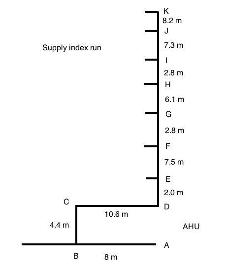
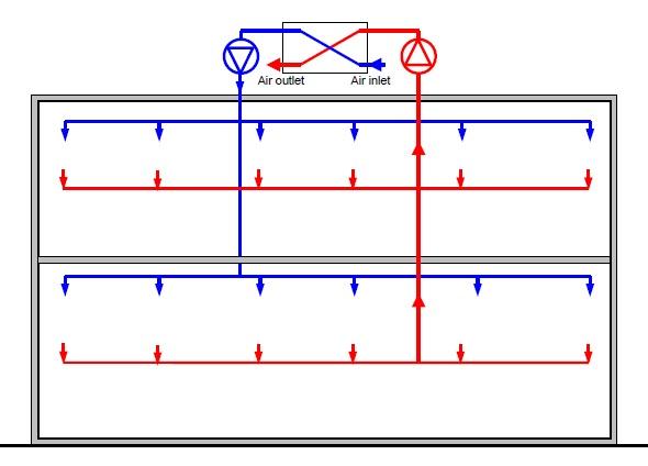
Figure 2 Office building dimensions for the maximum potential VRF system pipework

However, the likely maximum refrigerant pipe length between the condenser and furthest evaporator units could be roughly represented by the dimensions of the office building as shown below in figure.
Figure 2 Office building dimensions for the maximum potential VRF system pipework
Advertisement
According to the measurements, the maximum pipe length encountered would be approximately 6 + 18 + 54.5 = 78.5m. Thus, the size of the building where VRF may be installed is sufficiently small and any possible system inadequacy may be avoided. However, before selecting an exact VRF system the compliance with manufacturer data and the office building would be checked in order to make sure the longest path of refrigerant pipe is sufficiently short.
In conclusion, the VRF disadvantage in term of limited pipe lengths should not be a problem for the AC system design in the building located in Singapore.
1.2.2.2 VRF Conclusion
The key strengths and weaknesses were identified for the VRF systems. Those are the minimum space requirement, sensible control of building zones and good energy efficiency. However, the key disadvantages are that the system only provides cooling/heating and separate ventilation system would be required. Thus, an air conditioning provided by VRF
would be satisfactory for the building in terms of low running costs, system accommodation and its fast precise response for cooling.
1.2.3 Final selection between VAV and VRF for full air conditioning system
As both VAV and VRF systems were found suitable for the air conditioning in Singapore, the key selection is to be based on the total energy efficiency, comfort and weight and rank results. According to the various literature sources, the total energy demand for air conditioning and ventilation is lower for the VRF system compared to VAV. The total energy reduction of up to 50% could be achieved, though the initial cost for installing VRF may reach 20% in excess to that of VAV. Moreover, the controllability and reliability of VRF systems are primary compared to VAV air conditioning systems. VRF systems use variable compressors which can maintain a precise temperature control within 0.6 degree C range. Therefore, based on the key assumptions and operation characteristics, the VRF system was chosen for the office building in preference to VAV.
However, the ventilation system was needed to be decided for use in conjunction with VRF. The fresh air requirements are directly linked to the people, thus a precise control of fresh air supply rate would be instrumental for minimising the total energy demand. The VAV system is suitable for such situation and therefore was selected. It is going to be installed separately from VRF providing the necessary amount of fresh, conditioned air for the particular building zones. Moreover, the heat recovery system can be included in the air handling unit and will be considered in the later sections of the report.
Thus, the two systems have been selected to provide HVAC for the office building. The cooling will be provided by VRF and ventilation with VAV systems separately. The option of using two systems was highly dependent on the overall energy efficiency and comfort. Thus, the lower energy demand and better comfort levels inside the building zones would be achieved due to less amount of energy being used for cooling and/or ventilation.