Design Portfolio
JIA JOY HU 2023

ii
Contents.
Selected Architecture Scale:
Learning Amidst the Scent of Wood
Toyo Ito & Associates, Architects | Institutional Building - Singapore | 100% SD, 100% DD
Kagawa Prefectural Gymnasium Competition
Toyo Ito & Associates, Architects | Sports Architecure - Kagawa, Japan | Competition
Winery for the People
Harvard GSD Fall 2016 Option Studio | Architecture - Omishima, Japan | Professor Toyo Ito
Sanwa Showroom
Keiji Ashizawa Design Co. Ltd | Retail Interior Fit-out - Hangzhou, China | SD to 100% Construction
Shinjuku Tokyu Milano Hotel
Keiji Ashizawa Design Co. Ltd | Luxury Hotel Interior | SD, DD
Liberty Olonia Office and Atelier
Keiji Ashizawa Design Co. Ltd | Adapted Re-use - Milan, Italy | 1st Prize Competition
Selected Urban + Landscape Scale:
The Soul of Nørrebro : Climate Adaption Copenhagen
SLA Architects | 1st Prize Competition, Nordic Built Cities Challenge
Engaging Ecotones: Laguna Gloria Sculpture Park
Reed Hilderbrand LLC | 1st Prize Competition + Subsequent Masterplan
The Urban Sieve
Harvard GSD Spring 2017 Option Studio | Urban Design - India | Professor Christopher C.M. Lee
Land[scape] Banking
Harvard GSD Spring 2015 Core Studio | Landscape Urbanism | Professors: David Mah + Chris Reed
02. 06. 01. 05. 03. 04. 08. 09. 10. 1
07.
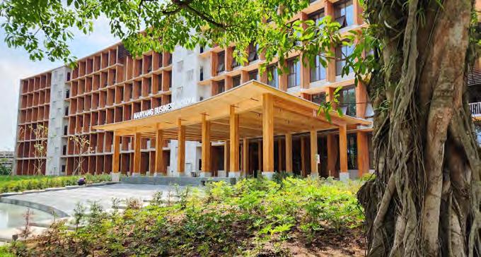
LEARNING AMIDST THE SCENT OF WOOD
Location: Nanyang Technical University Business School , Singapore
Project Type: All Timber Construction Business School
Phase: 100% Schematic Design / 100% Design Development
Role: Project Team Member at Toyo Ito & Associates, Architects
Area: 40,000 sq meters
2 01.
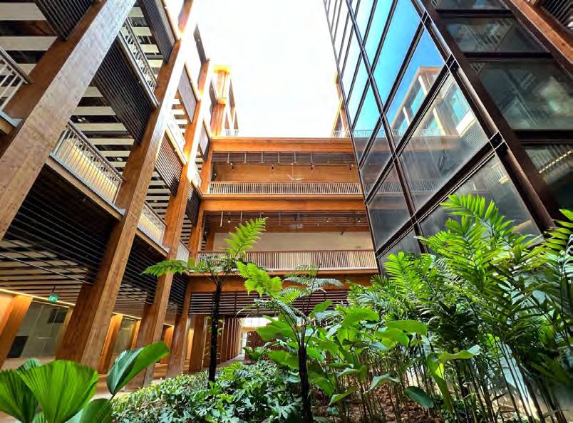
Toyo Ito & Associates, Architects won the international competition to design a new, all-timber business school in Singapore for Nanyang Technical University. With a gross floor area of 40,000 sqm, this new business school is a single-building solution that promotes harmony and interaction between faculty, undergraduate and post-graduate students.
The design is centered around the central, collaborative axis. This N-S linear axis becomes the new third space, a place for unexpected encounters and exchanges away from structured and programmed classrooms and offices. The entire building is laid on a radius so that its slightly curved form embraces visitors, creating a welcoming gateway to the rest of the campus and the nearby Yunnan Garden.
This was my main project during my two years working at Toyo Ito & Associates. As part of a 4 person team on the design architects side, we collaborated with executive architects in Singapore, RSP Architects in order to develop the plans and details from schematic design through design development. This required constant communication between the Japanese side and the Singaporean teams.
3
EMPHASIZING THE TIMBER STRUCTURE
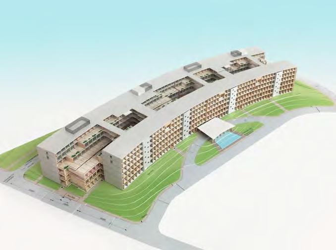
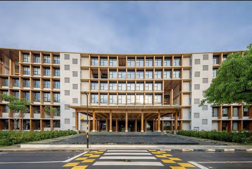
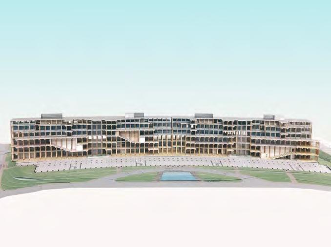
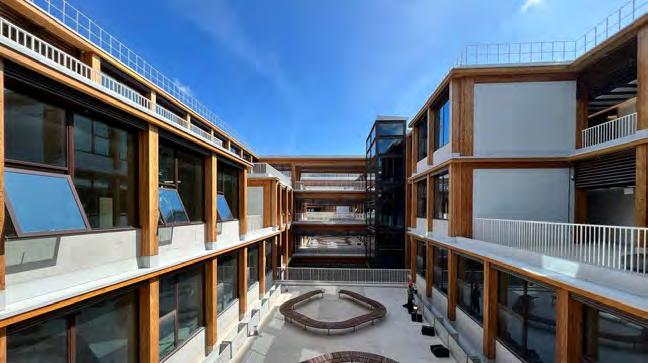
The building structure employs a modular timber post and beam system, its uniform, non-hierarchical deep structure allows program to be flexibly fit within the modules, and also allows for adaptability. This post-and-beam structure extends visibly on the facade as horizontal and vertical fins, reinforcing the timber structure of the building while creating a deep coffered facade, which diffuses exposure to direct sunlight during hot Singapore summers. The entire building is laid on a radius so that its slightly curved form embraces visitors, creating a welcoming gateway to the rest of the campus and the nearby Yunnan Garden.
4
Overall 1:300 Model
Entry Drive at Pedestrian Level
SectionalStudyofModelCentralCollaborativeAxis
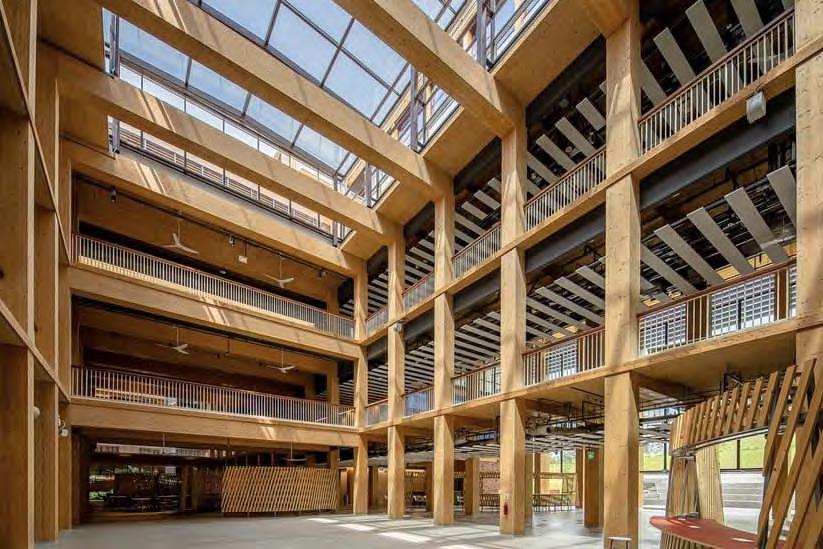
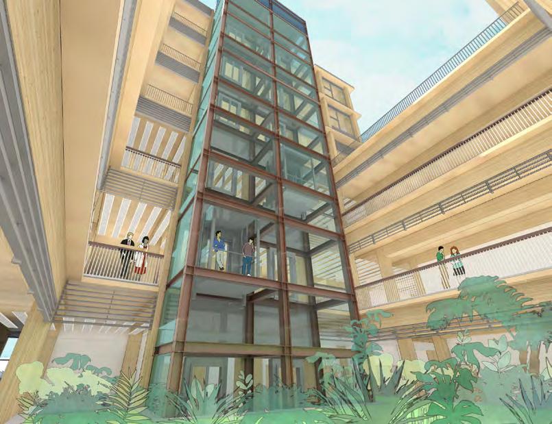
Central A trium Skylight
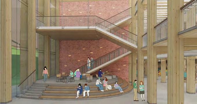
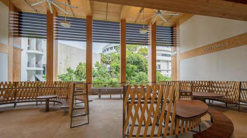
CONNECTIVE SOCIAL SPACES
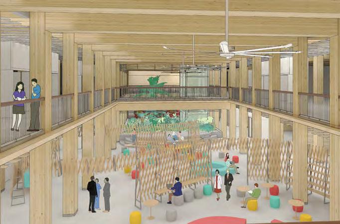
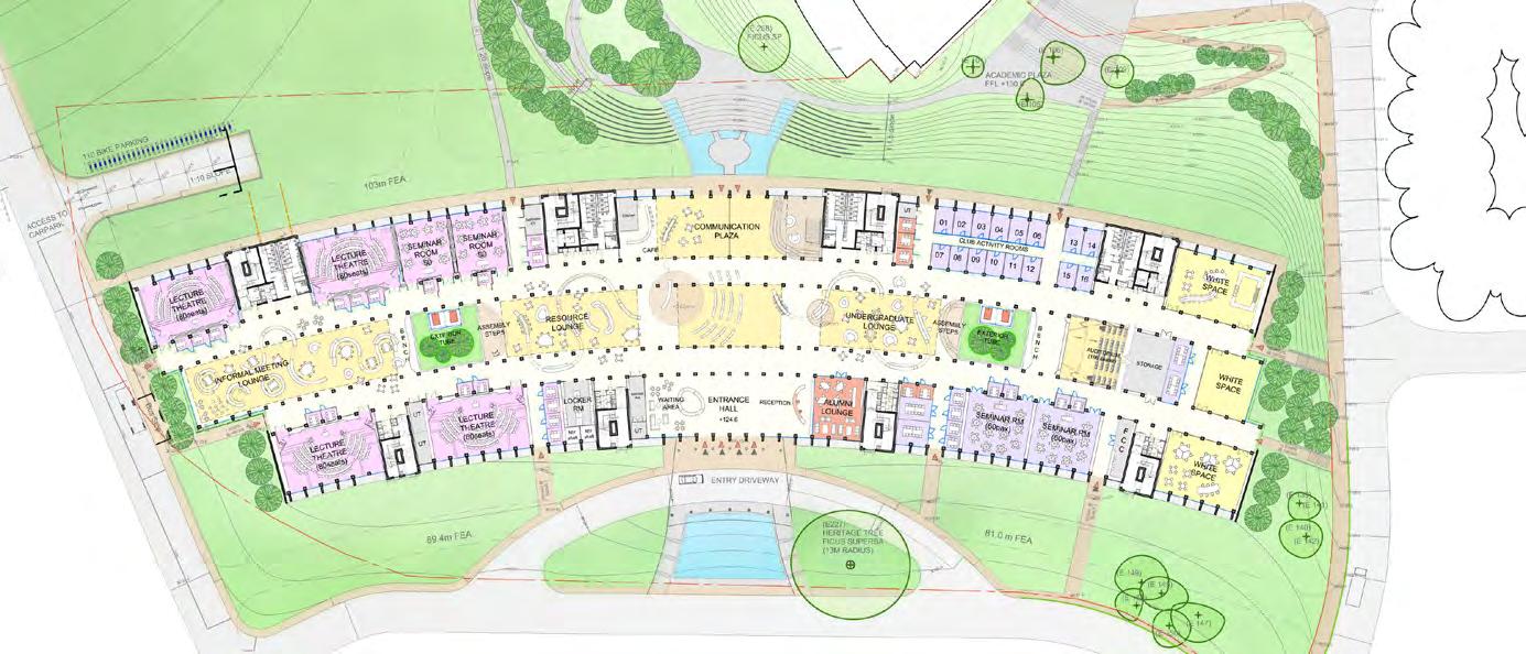
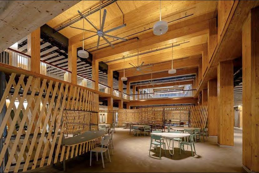
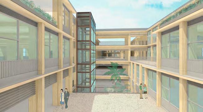
The program of the building is clearly divided between floors, with teaching seminar spaces on the 1-3F, research centers on the 4F and faculty offices on the 5-6F. The undergraduate wing extends to the north and the graduate wing to the south, but both are connected at the center by a large, social atrium, creating a strong sense of a larger community. Double-height “green social spaces” are intermittently placed on the facade to enourage social and academic mixing. The classrooms flanks the two sides of the central axis, where the “continuous assembly” is placed. Here, double-height, flexible, social and learning lounges are placed, turning the main N-S axis into a central place of gathering.
Central Collaborative Axis
0 10m 5
Central Collaborative Axis
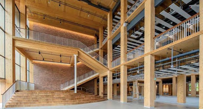
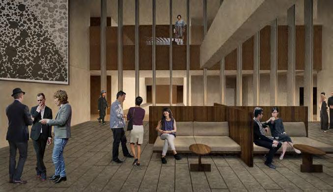
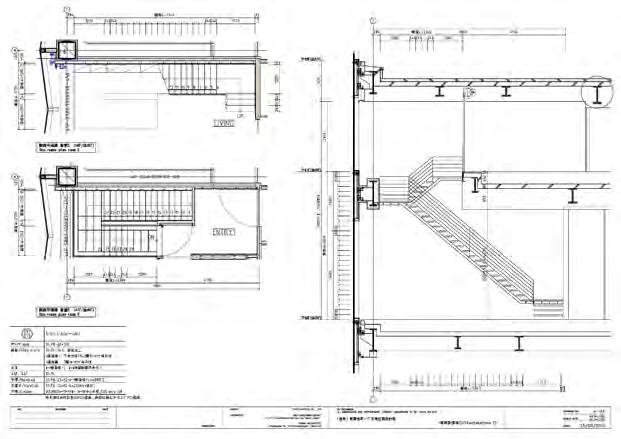
DETAIL DESIGN OF CENTRAL ATRIUM SPACE
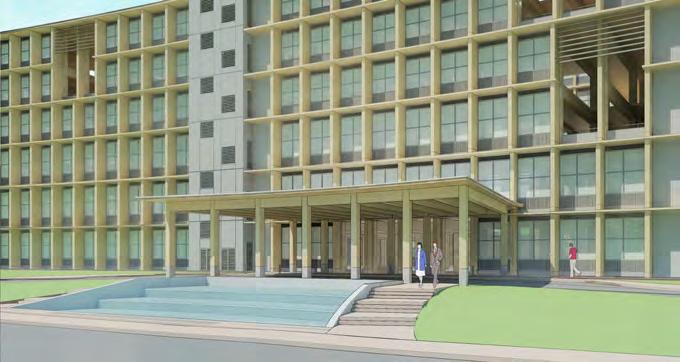
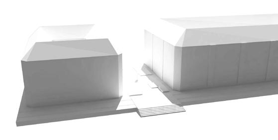
The central atrium and main event space are at the core of our building. Situated on the main transverse axis that passes through the building (E-W) these two spaces invite visitors in together to mingle, collaborate and relax. Some of the main features of this event space is the front entrance canopy and the grand staircase and the cascade water amphitheater at the back side of the building. The entrance canopy is meant to showcase structural timber and CLT in the same way the building does, welcoming in people with its curved form. The grand staircase is a stage and a collaborative platform. It reinforces the wooden nature of the building by showcasing CLT as the main structural element.
Entry Canopy and Fountain at East Facade
6
1300 400w x 600d TYPICAL SECONDARY BEAM 400x450 TYPICAL COLUMN 400w x 600 d TYPICAL BEAM PIPE EMBEDDED INTO FIN 200mm CLT ACTS AS BAND BEAM BOLLARDS IN LINE WITH COLUMN CTRLINE 500 3360 11065 2000 100 1300 90° 4860 1500 500 400x450 TIMBER COLUMN FRONT ELEVATION CONC FOOTING ACTS AS BOLLARD SCREED (T=50 TO T=100) 160 CLT SLAB TYP ALUMINUM CAP 400wX600d BEAM 400Wx600d BEAM 5085 700 400 SLOPE ALUMINUM FLASHING (T=3) ACCOYA COVER (T=27) 160MM CLT 200x160 BEAM UPSTAND ALUMINUM FLASHING (T=3) FIRE RATED BOARD (T=15) BUIILDUP FOR GRADIENT + WATERPROOFING 200 100 150 16010 500 400 600 85 70 1:80 SLOPE ALUMINUM FLASHING (T=3) ACCOYA COVER (T=27) 160MM CLT FIRE RATED BOARD (T=15) BUIILDUP FOR GRADIENT + WATERPROOFING 200x160 BEAM UPSTAND ALUMINUM FLASHING (T=3) 160 50 150 500 400 600 45 200 30 TOYO ITO & ASSOCIATES, ARCHITECTS Academic Building South ENTRY CANOPY- OPT 2 (1500 fins and non-cut horizontal fin) 1:10014-08-2018 -1:20 DETAIL B-B' (THICKENED CLT) 1:20 DETAIL A-A' (TYPICAL) 250 30 200 16010 ALUMINUM COVER 160MM CLT 10MM ACCOYA COVER EPOLS 550 2500 12000 2000 200MM ALUMINUM UPSTAND 900 75 Ø PIPE 1:80 SLOPE 1:80 SLOPE 1:100 SLOPE 1:80 SLOPE 1:80 SLOPE 1:100 SLOPE 560 520 800 900 160 CLT SLAB TYP ALUMINUM ROOF TIMBER COLUMN 300wX600d BEAM 300Wx600d BEAM CONC FOOTING ACTS AS BOLLARD 1:100 SLOPE 1:80 SLOPE 1:100 SLOPE 1:80 SLOPE 5035 TOYO ITO & ASSOCIATES, ARCHITECTS Academic Building South ENTRY CANOPY - ROOF DRAIN 1:10013-02-20181:20 ROOF DETAIL A-A 1:20 ROOF DETAIL B TIMBER COLUMN 300X800 TIMBER FIN 75Ø PIPE DETAIL B ACCOYA WOOD COVER 1:50 Detail of Drain
Entry Canopy
Detail of Drain Pipe
Section 1:60 SLOPE ALUMINUM UPSTAND 1:57 SLOPE 1:68SLOPE 1:60 SLOPE 1:57 SLOPE 1:68SLOPE +100mm screed +100mm screed +100mm screed FFL 124.6 6M WIDE ROAD 1:80 SLOPE SECTION A-A 400X450 TIMBER COLUMN 160MM CLT SLAB ALUMINUM ROOF 400 X 600 BEAM ALIGNED WITH FRONT OF COLUMN 75Ø DRAINAGE PIPE EMBEDDED WITHIN COLUMN 4.2 SIGN TO BE DESIGNED THICKENED CLT SLAB 200MM TO ACT AS BAND BEAM FOR CANTILEVERED EDGE 4860 1250 5085 1250 200 11065 600 700 700 700 450 4520 4915 2000 4550 TOYO ITO & ASSOCIATES, ARCHITECTS Academic Building South 1:10014-08-2018 1:20 ROOF DETAIL F-F' ENTRY CANOPY- OPT 2 - Roof (1500 fins and non-cut horizontal fin) 1:60 SLOPE ALUMINUM UPSTAND 75 Ø PIPE 1:57 SLOPE 1:68SLOPE 1:80 1:53 1:60 SLOPE 1:57 SLOPE 1:68SLOPE 1:80 1:53 +100mm screed +100mm screed +100mm screed +50mm screed +50mm screed +100mm screed +100mm screed +100mm screed 1300 TIMBER COLUMN 300X800 TIMBER FIN 75Ø PIPE 30MM ACCOYA WOOD COVER 560 520 156 1300 75 75 75 75 FFL 124.6 6M WIDE ROAD 1:80 SLOPE SECTION A-A 400X450 TIMBER COLUMN 160MM CLT SLAB ALUMINUM ROOF 400 X 600 BEAM ALIGNED WITH FRONT OF COLUMN 75Ø DRAINAGE PIPE EMBEDDED WITHIN COLUMN 4.2 SIGN TO BE DESIGNED THICKENED CLT SLAB 200MM TO ACT AS BAND BEAM FOR CANTILEVERED EDGE 4860 1250 5085 1250 200 11065 600 700 700 700 450 4520 4915 2000 4550 CUT BACK TIMBER COLUMN ALUMINUM UPSTAND 75Ø PIPE 30MM ACCOYA WOOD COVER ROOF SCREED T=100 TO T=50 WATERPROOFING TIMBER COLUMN NOTCHEDTO FIT PIPE CLT SLAB 250 1300 100 50 TOYO ITO & ASSOCIATES, ARCHITECTS Academic Building South 1:10014-08-20181:20 ROOF DETAIL E-E' DETAIL E-E' 1:20 ROOF DETAIL F-F' DETAIL F-F' ENTRY CANOPY- OPT 2 - Roof (1500 fins and non-cut horizontal fin)
Entry Canopy
1:250
1:50
1:250
Constructed
7
CLT Grand Staircase
160 300 142 T=10 ACOUSTIC UNDERLAY STEEL NOSING 25X75 T=15 TIMBER FLOORING T=20 x 2 CEMENT BOARD TIMBER BATTEN BUILD-UP ROCKWOOL INSULATION T=10 ACOUSTIC UNDERLAY CLT SLAB T=160 15 10 20 TIMBER FLOORING T=10 ACOUSTIC UNDERLAYER 2X CEMENT BOARD T=20 UB 203X203X127 TIMBER BATTEN T=10 ACOUSTIC UNDERLAYER ROCKWOOL INSULATION 80KG/M3 T=12 STEEL PLATE T=10 ACOUSTIC UNDERLAYER CHANNEL U 150X75X9 TIMBER COVER ARCHITECTS Academic Building South GRAND STAIRCASE DETAIL 1:622-09-2018 A-418DETAIL D-D - TYPICAL STEPS BUILD-UP SLAB BUILD-UP 160 300 142 T=10 ACOUSTIC UNDERLAY STEEL NOSING 25X75 T=15 TIMBER FLOORING T=20 x 2 CEMENT BOARD TIMBER BATTEN BUILD-UP ROCKWOOL INSULATION T=10 ACOUSTIC UNDERLAY CLT SLAB T=160 151020 15 10 TIMBER FLOORING T=10 ACOUSTIC UNDERLAYER 2X CEMENT BOARD T=20 203 UB 203X203X127 TIMBER BATTEN T=10 ACOUSTIC UNDERLAYER ROCKWOOL INSULATION 80KG/M3 T=12 STEEL PLATE T=10 ACOUSTIC UNDERLAYER CHANNEL U 150X75X9 TIMBER COVER 75 ASSOCIATES, ARCHITECTS Academic Building South GRAND STAIRCASE DETAIL 1:622-09-2018 A-418DETAIL D-D - TYPICAL STEPS BUILD-UP - TYPICAL SLAB BUILD-UP 180 140 140 40 40 40 40 20MM THICK MS PLATE (6) M16 GR8.8 X 300 BOLTS UB 203 x 203 x 127 50 160 203 120 280 280 1860 100 9 5 R44 R23 75 50 143 173 300 60 1510 150 143 WELDED TOGETHER 19Ø STEEL ROD OR 21.7Ø HOLLOW ROD 30Ø HIGH STRENGTH TENSILE ROD HUNG FROM ABOVE 40Ø HOLLOW STEEL SLEEVE 40Ø ADJUSTABLE THREADED SLEEVE STEEL PLATE T=6 STEEL PLATE T=6 STEEL -L 30X30 T=5 CLT SLAB T=160 STEEL COVER T=9 STEEL PLATE 6X25MM WOODEN HANDRAIL UB 203 x 203 x 127 FLOOR FINISH 10mm ACOUSTIC UNDERLAYER T=20 CEMENT BOARD 2020 268 5 100 15 268 160 80 50 15 10 150 60 143 75 110 60 18 FLOOR FINISH CLT SLAB SALVAGED BRICK STRUCTURAL CONC WALL BEHIND CORRUGATED GALVANISED STEEL SHEET ANCHOR @ 1M c/c 10mm ACOUSTIC UNDERLAYER RECESS IN THE RC WALL TO CAST IN THE BASE PLATE MORTAR T=20 CEMENT BOARD TOYO ITO & ASSOCIATES, ARCHITECTS Academic Building South GRAND STAIRCASE DETAIL 1:622-09-2018 A-418Elevation A-A Detail Connection to Concrete Core Detail Connection of Hanging Rod 180 140 140 40 40 40 40 20MM THICK MS PLATE (6) M16 GR8.8 X 300 BOLTS UB 203 x 203 x 127 50 160 203 120 280 280 18 60 100 9 5 R44 R23 75 50 143 173 300 60 15 10 150 143 WELDED TOGETHER 19Ø STEEL ROD OR 21.7Ø HOLLOW ROD 30Ø HIGH STRENGTH TENSILE ROD HUNG FROM ABOVE 40Ø HOLLOW STEEL SLEEVE 40Ø ADJUSTABLE THREADED SLEEVE STEEL PLATE T=6 STEEL PLATE T=6 STEEL -L 30X30 T=5 CLT SLAB T=160 STEEL COVER T=9 STEEL PLATE 6X25MM WOODEN HANDRAIL UB 203 x 203 x 127 FLOOR FINISH 10mm ACOUSTIC UNDERLAYER T=20 CEMENT BOARD 20 20 268 5 10015 268 160 80 50 15 10 150 60 143 75 110 60 18 FLOOR FINISH CLT SLAB SALVAGED BRICK STRUCTURAL CONC WALL BEHIND CORRUGATED GALVANISED STEEL SHEET ANCHOR @ 1M c/c 10mm ACOUSTIC UNDERLAYER RECESS IN THE RC WALL TO CAST IN THE BASE PLATE MORTAR T=20 CEMENT BOARD TOYO ITO & ASSOCIATES, ARCHITECTS Academic Building South GRAND STAIRCASE DETAIL 1:622-09-2018 A-418Elevation A-A Detail Connection to Concrete Core Detail Connection of Hanging Rod
Constructed CLT Grand Staircase
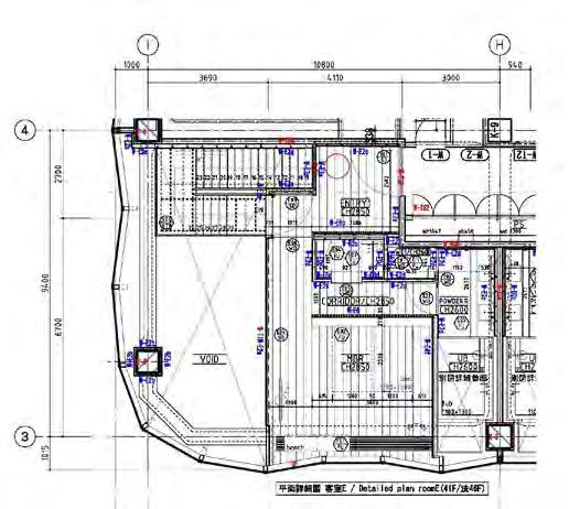
DETAIL DESIGN OF CENTRAL ATRIUM SPACE
Elevation C-C
Planted Atrium Elevator
1:10021-09-2018 A423


8 2190 2100 Opening 180 1000 2190 2100 Opening 180 1000 2190 2100 Opening 180 1000 2190 2100 Opening 180 1000 2190 2100 Opening 180 1000 2190 2100 Opening 180 1000 2190 2100 Opening 180 1000 2190 2100 Opening 180 1000 2190 2100 Opening 180 1000 2190 2100 Opening 180 1000 2190 2100 Opening 180 1000 2190 2100 Opening 180 1000 2290 250 1700 250 250 450 2350 250 1700 250 2350 250 1700 250 2350 250 1175 250 2350 250 1360 4025 4550 4025 4550 4550 2350 250 1175 250 4600 60 60 60 60 60 250 2540 2540 2540 2540 2540 2540 Tube -
Sect/Elev
Typical
-
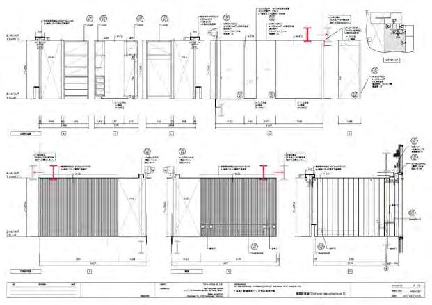
VARIOUS SLAB EDGE DETAILS
FACADE - C1Y-3 (EXT TUBE 4-6F - OFFICE )
BALUSTRADE - B2 (WOOD HANDRAIL W/ PLANTER ON 2F)
Central Axis Staggered Outdoor Terraces
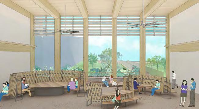
Collaborative Double-Height Space
9 50 50 160 200 600 20 120
1:100 slope SECTION FL THICKENED SLAB TO BEAR PLANTER WEIGHT DROP SLAB 20MM PEBBLE WASH FLR 19Ø ST ROD WOODEN HANDRAIL SCREED WITH MESH 50MM INSULATION BOARD WATERPROOFING MEMBRANE 100 200 11240 FL 320 5MM WIDE DIVIDING STRIP 800 520 300 520 1500 75 200 260 30MM COVER SIHPONIC RWDP 50 380 50 40 600 WEEPHOLE FOR DRAINAGE 1100 200 60 30 200 MIN 200 TYPE B1 - HOLDING TYPE TYPE B2 - HOLDING W/ PLANTER HANDRAIL TYPE B
SECTION TIMBER COLUMN BEHIND PRECAST PANEL LARCH LAYER T=27 34Ø STEEL HANDRAIL 260 520 160 450 320 CLT SLAB EXTENDS 27MM ACCOYA WOOD COVER INTERIOR 420 150X150 STEEL I-BEAM ALUMINUM SKIRTING TYPE C2 STEEL ROD TYPE C3 STEEL ROD W/ PLANTER HANDRAIL TYPE C TYPE C1 EXT TUBE TOYO ITO & ASSOCIATES, ARCHITECTS Academic Building South Handrail Key 1:2018-09-2018 280 280 BALUSTRADE - C2X-4 ( STEEL HANDRAIL 5-6F Gable End Opening) SECTION TIMBER COLUMN BEHIND PRECAST CONCRETE GABLE END WALL 260 160 75 1100 410 2400 BALUSTRADE - C2X-3 ( STEEL HANDRAIL 5-6F BRIDGE CORRIDORS) TIMBER COLUMN BEHIND SOLID 19Ø ROUND ROD ANCHORED TO FIN 34Ø STEEL HANDRAIL CLT SLAB EXTENDS LARCH LAYER T=27 27MM ACCOYA WOOD COVER SECTION TIMBER FIN BEHIND 160 50 1100 100 120 FL T=680 LARGE SPAN BEAM 340 680 560 680 560 T=680 LARGE SPAN BEAM 75 70 200 180 75 ALUMINUM UPSTAND TO MATCH COLUMN COLOR 75 34Ø STEEL HANDRAIL SOLID 19Ø ROUND ROD ANCHORED TO FIN SCREED UPSTAND ALUMINUM FLASHING 545 145 175X175X12 STEEL ANGLE FLUSH WITH EDGE OF COLUMN TYPE C2 STEEL ROD TYPE C3 STEEL ROD W/ PLANTER HANDRAIL TYPE C TYPE C1 EXT TUBE TOYO ITO & ASSOCIATES, ARCHITECTS Academic Building South Handrail Key 1:2002-10-2018
Detail Planter Detail
Concrete Detail
Facade
Gable End
GATEWAYS FOR KAGAWA
Location: Takamatsu, Kagawa, Japan
Project Type: Kagawa Prefectural Competition
Phase: Competition
Role: Competition Team Member at Toyo Ito & Associates, Architects
Area: 30,000 sq meters
Projected Budget: 19 million USD (1.9 billion JPY)
10 02.
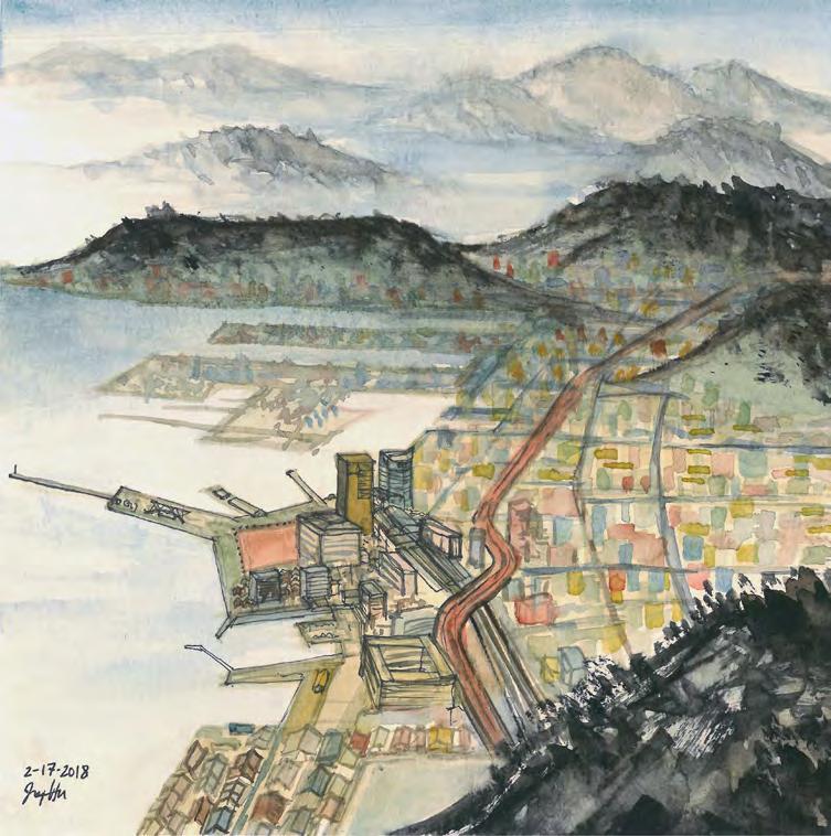
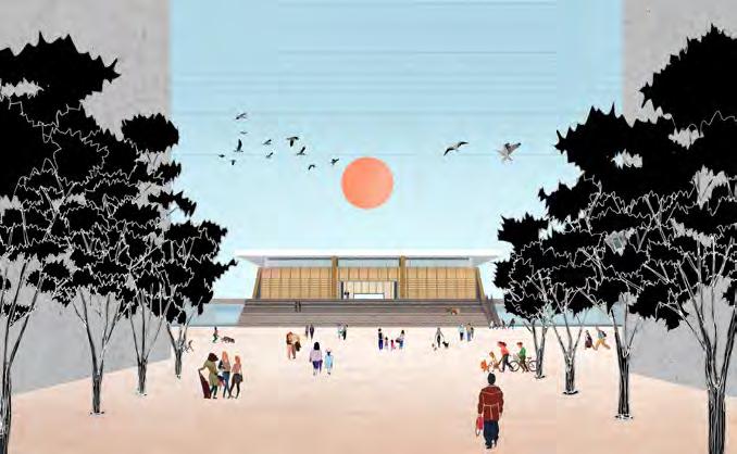
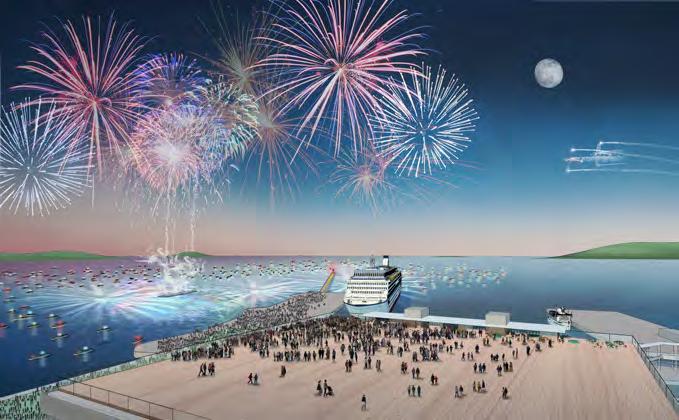
“Gateway to the Land, Gateway to the Sea”
Toyo Ito & Associates, Architects participated in the competition to design a gymnasium complex in Takamatsu that could become the new emblem of Kagawa Prefecture. After WWII, Takamatsu City became the foundation of contemporary Japanese Architecture, founding a spirit of creation based upon tradition.
The design of Kagawa Prefectural Gymnasium pays homage to this spirit of tradition to create a sacred and innovative contemporary space for sports by creating new gateways to the city. The site of Takamatsu lies at the interface between land (mountains) and water. We deliberately play upon this intersection, creating gateways for both land and water.
11
Basketball Game (8800 Capacity)
Concert (8000 Capacity)
Reception (4500 Capacity )
Possible Configurations of the Main Arena

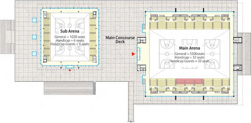
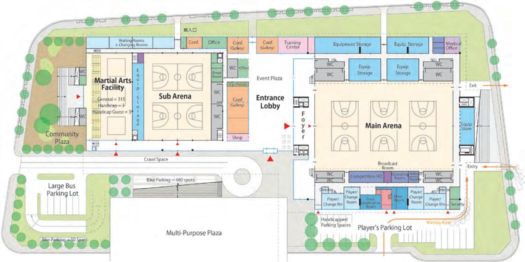
12 1F Plan 0 10 30m
すのこ平面図 コンサート エンドステージ 総座席数:4450席 レセプション サイドステージ 座席平面図 すのこ平面図 固定席:4376席 可動席:0席 仮設席:3656席 総座席数:8032席 固定席:5500席 可動席:0席 仮設席:4525席 総座席数:10025席 固定席:5500席 可動席:2656席 仮設席:497席 総座席数:8653席 バスケットボール コンサート センターステージ コンサート エンドステージ 固定席:2750席 可動席:0席 仮設席:1700席 総座席数:4450席 レセプション サイドステージ 座席平面図 すのこ平面図 固定席:4376席 可動席:0席 コンサート センターステージ コンサート エンドステージ 固定席:2750席 可動席:0席 レセプション サイドステージ 座席平面図 Mezzanine Plan GL+3m Elevated Walk connects to Takamatsu Symbol Tower 2F Plan 0 10 30m Roof Plan GL+21m GL+6m
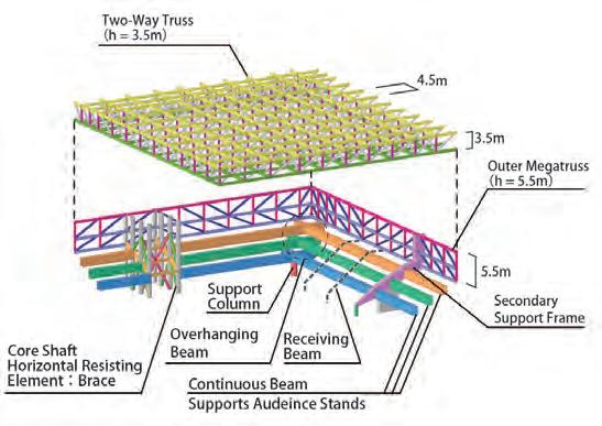
Sub Arena Martial Arts Facility Wooden Louvres + Horizontal Glass Blackout Curtain High Side Light Fire-resistant Plate Cover Exhaust Wind Indirect Light Indirect Light Blackout Curtain Main Arena Continuous Secondary Beam + Horizontal Glass Fire-resistant Plate Cover Sound Indirect Light Wind Sub Arena Structure Main Arena Structure
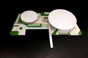
Gateway to the Land : Sub Arena
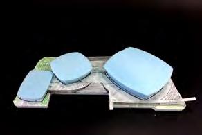
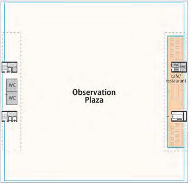
Structural Concept for Observatory Roof
Watching Fireworks on Observatory Plaza
13
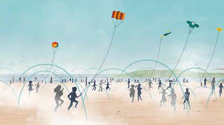
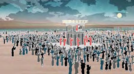
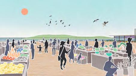
Bon Odori Dance Weekend Farmer’s Market Summertime Mist Jets
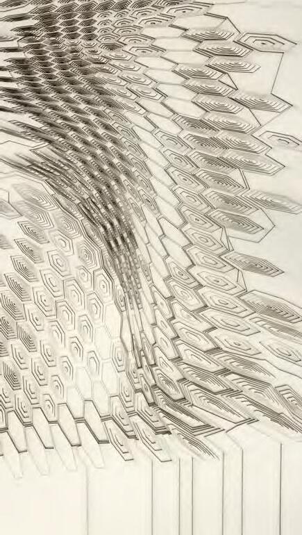
WINERY FOR THE PEOPLE
Location: Omishima Island , Japan
Studio: Harvard GSD Option Studio - Fall 2016 - Architecture/Landscape Design
Professors: Toyo Ito, Jun Yanagisawa, Julia Li
Area: 4000 sq m site / 665 sq m building
Award: Featured in LIXIL Gallery + 2016 Japanese Junction Exhibition
14
03.
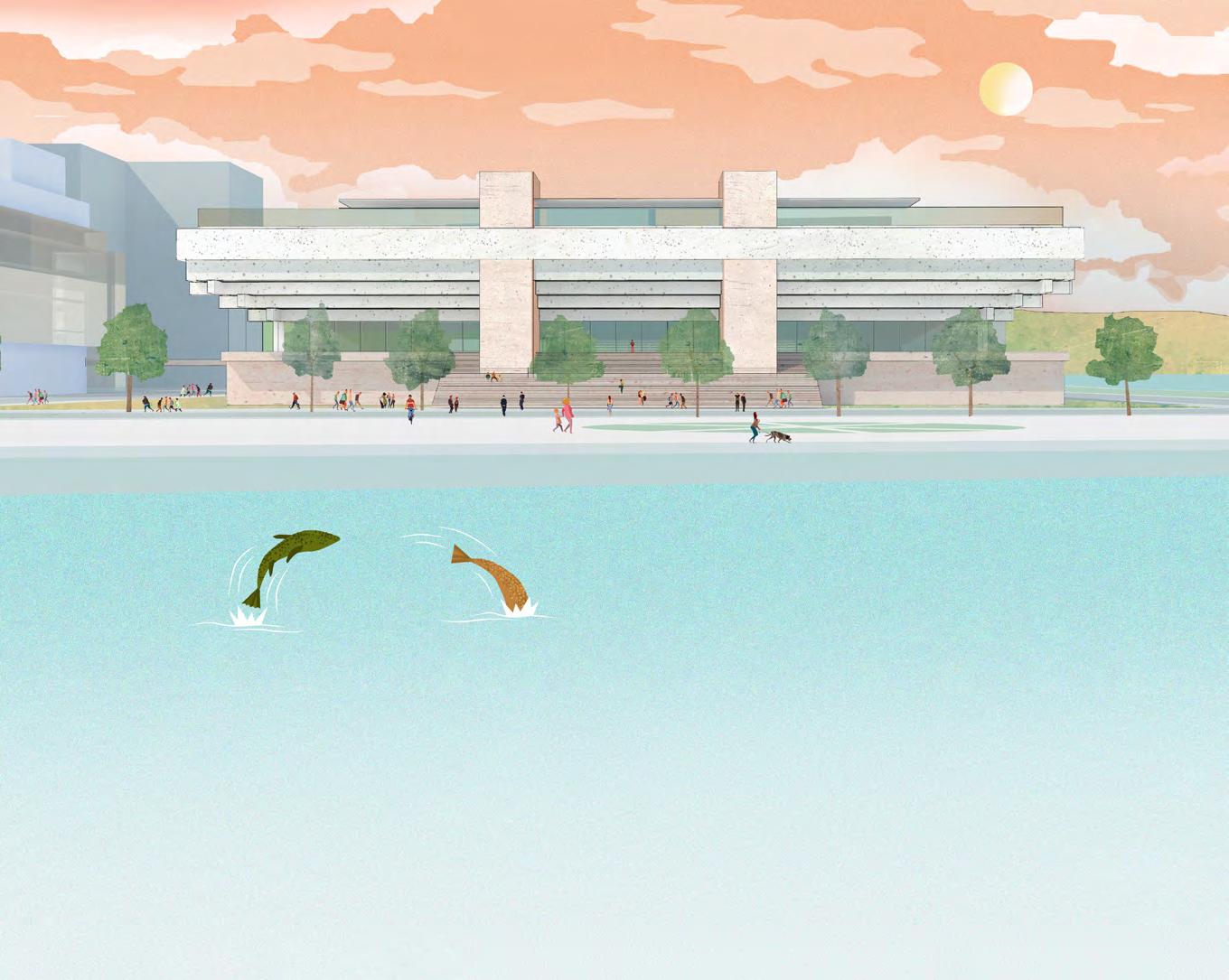
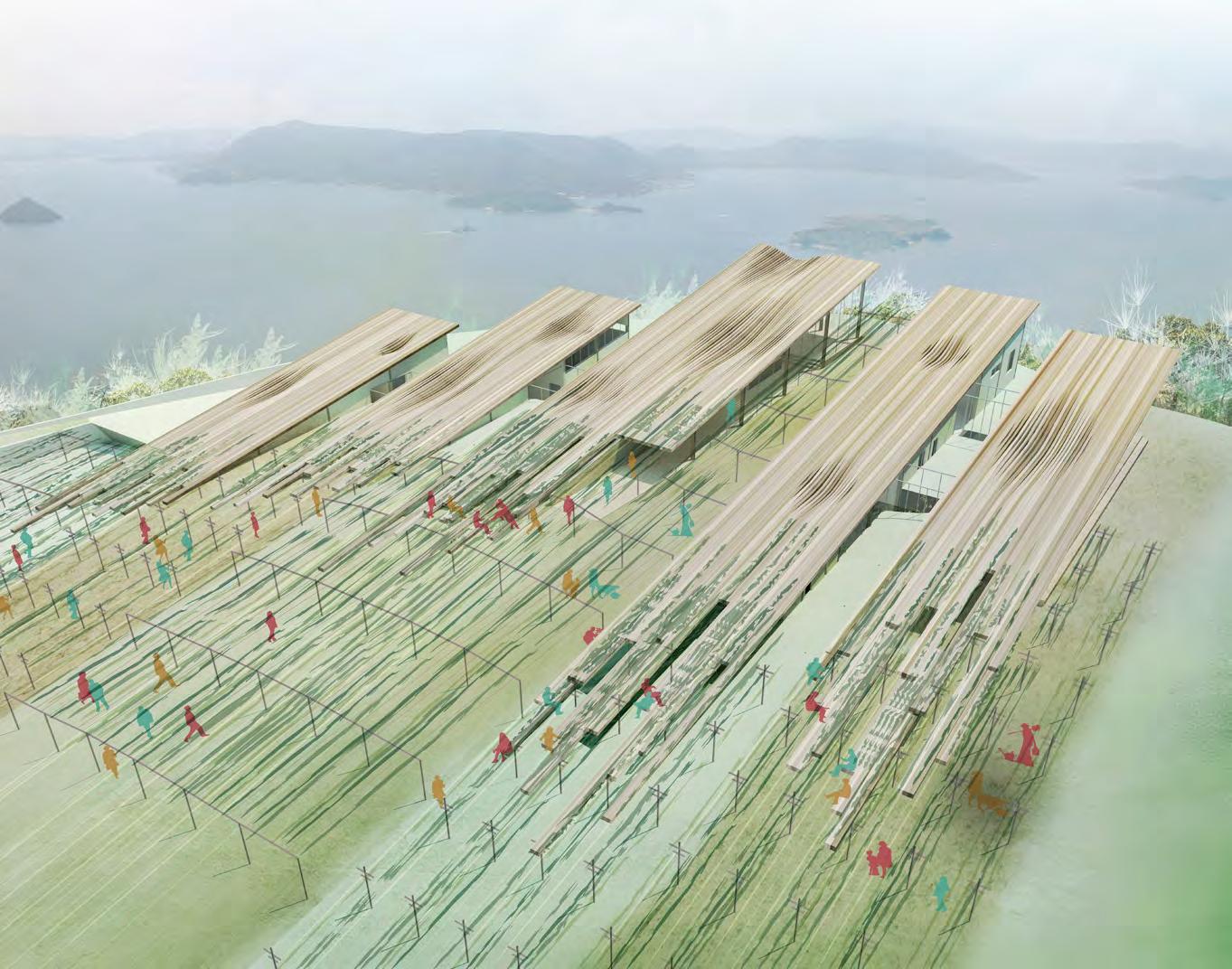
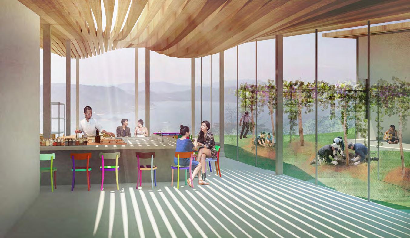
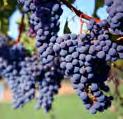
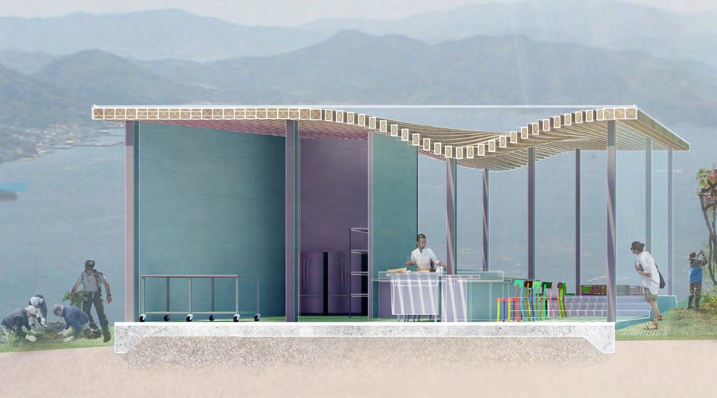
This winery is conceived of as an educational winery where people can live short-term to learn the art of wine-making on Omishima Island. It is meant to be a teaching winery where locals and visitors can come to partake in the wine-making process to learn from those living and working on the winery.
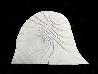
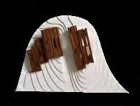
Inspired by the landscape, the design tries to incorporate two contrasting systems within the design: the naturally undulating cliff carved away by the ocean tides and the rigid, ordered geometry typical of productive vineyard plantings.
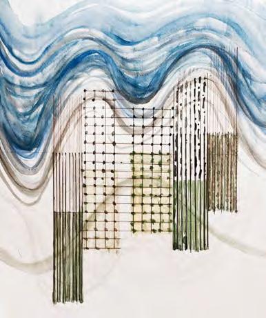

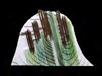
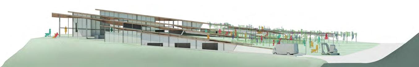
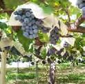
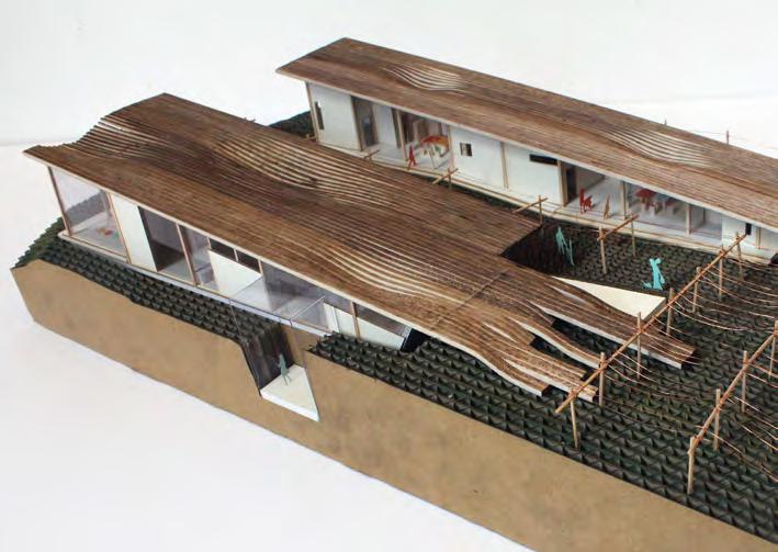
The architecture is derived from the two types of vine structures, the traditionally Japanese Tanaishiki-Saibai overhead structure and the traditional European linear vineyard rows. The architecture emerges from these two structures as roof planes. The roof planes have dips in certain zones to allow for light, depending on the programmatic need of the space.
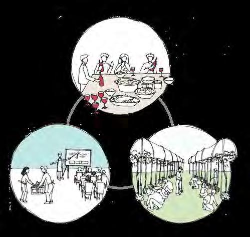
LIVE WORK LEARN 15
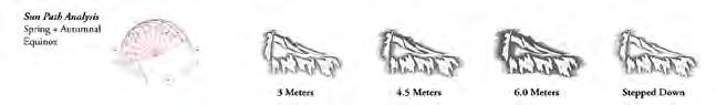
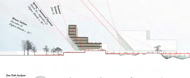
DESIGNING A TEACHING VINEYARD FOR ALL SEASONS

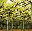
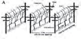
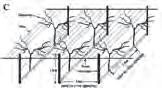
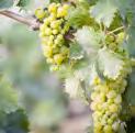
16 JAPANESE VINEYARD EUROPEAN VINEYARD KOSHU white wine grape CHARDONNAY white wine grape MUSCAT BAILEY A light red wine grape MERLOT dark blue-colored wine grape LINEAR PLANTING TANAISHIKI - SAIBAI
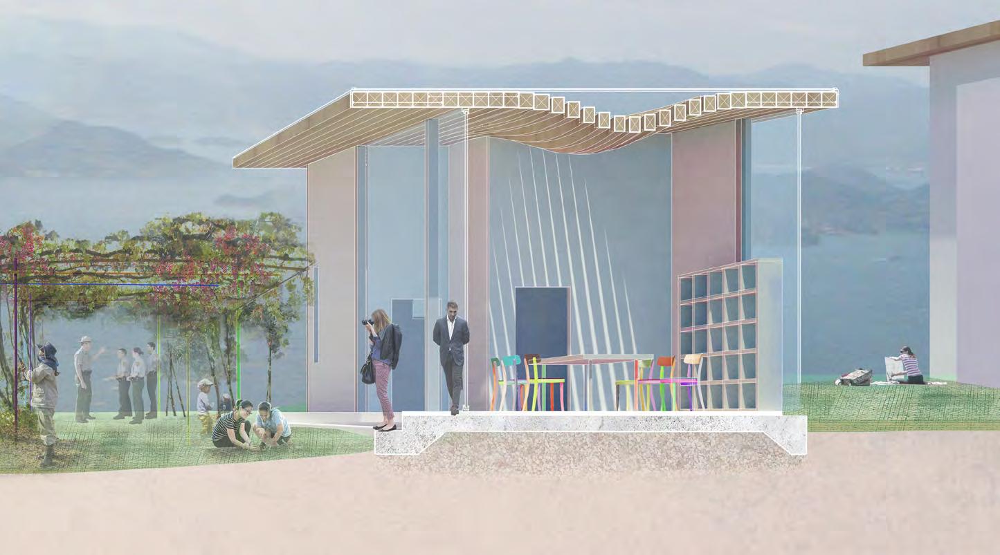
Interior View of Teaching Kitchen and Outdoor Vineyard Tanaishiki-Saibai Teaching Vineyard
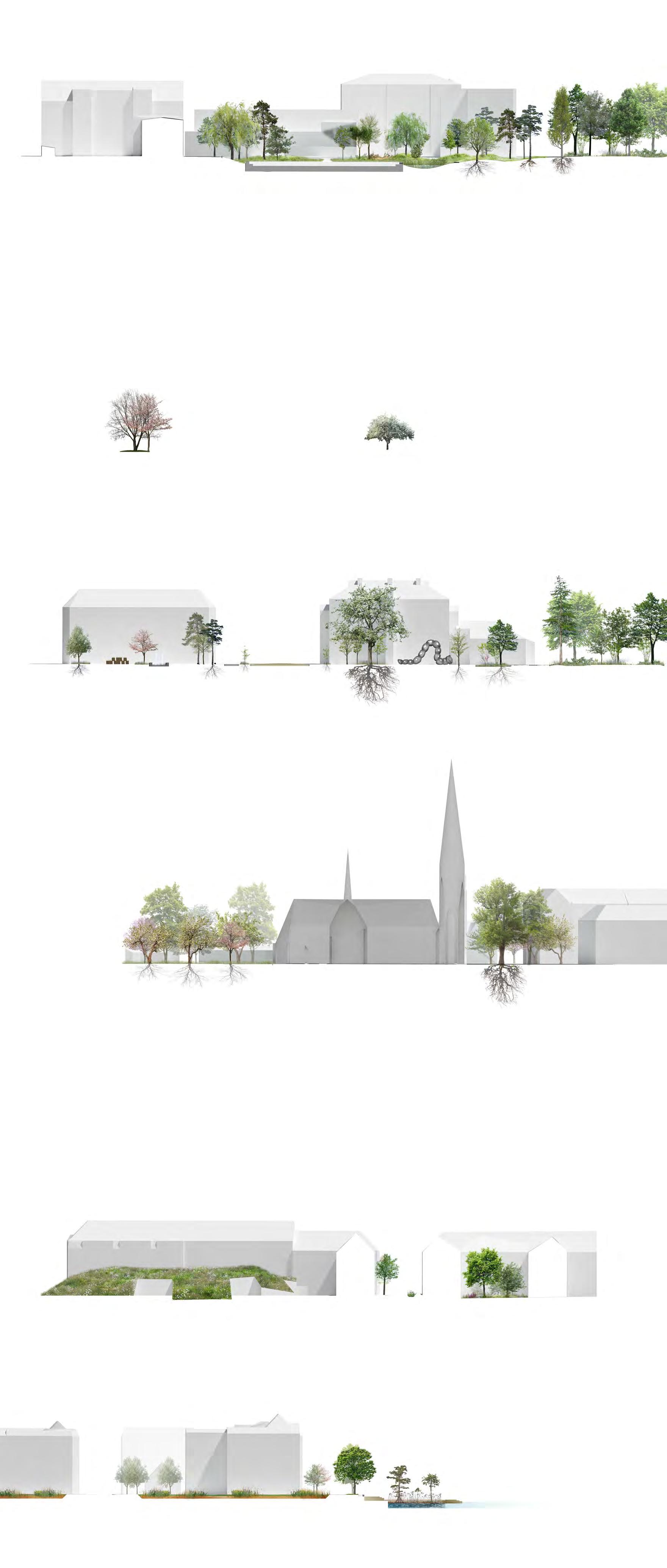
Elevation approaching from Road
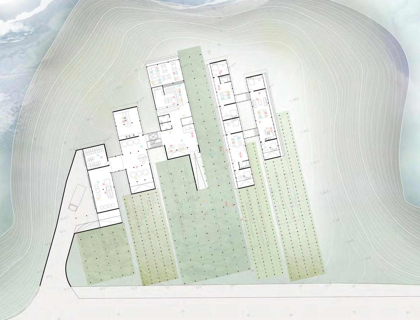

1 2 3 7 8 8 9 6 4 5 0 10m
Wine-making = 225 sq m 1. Loading Dock 2. Crush Sort, De-stem 3. Ferment, Press, Filter 4. Bottle 5. Mature + Store Restaurant + Tasting = 215 sq m 6. Lobby 7. Restaurant Auberge = 225 sq m 8. Workshop Space 9. Shared Common Space (Kitchen, Dining) 10. Rental Rooms Total = 665 sq m
Elevation from Ocean
17
Elevation from Ocean
18
Section
Perspective of Shared Learning Space
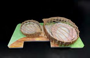
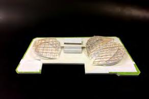
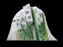
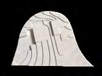
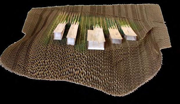
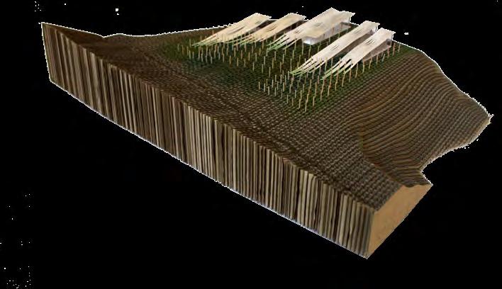
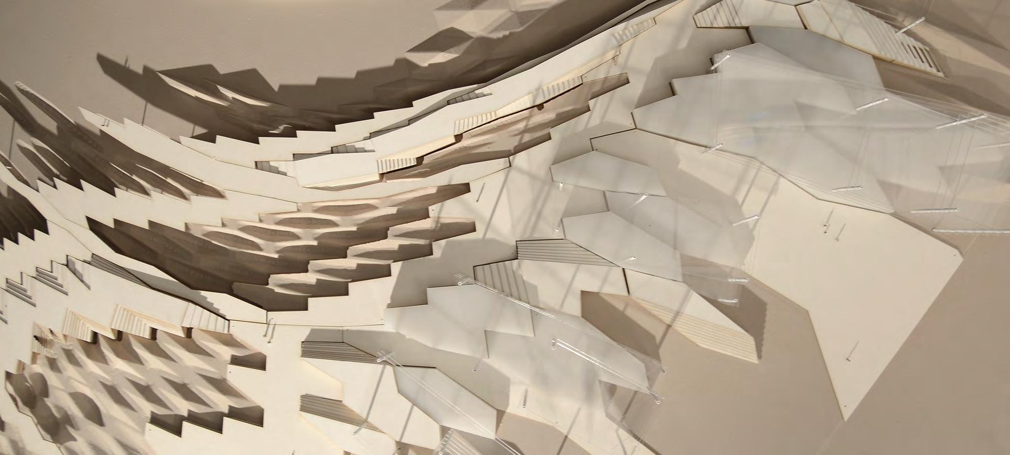
1:200 Site Model of Site Concept
MODELING THE SHARED LEARNING SPACE
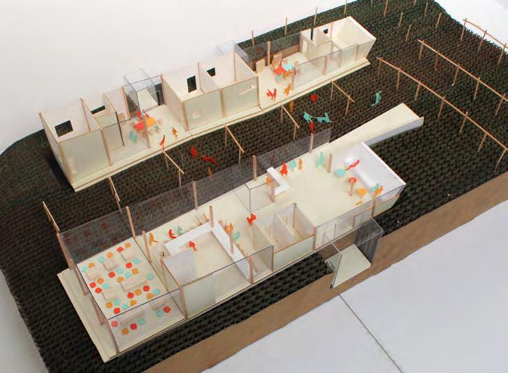
 Interior View of Shared Learning Space
19
Curvatures of Roof Structure
SANWA SHOWROOM
Location: Hangzhou, China
Project Type: Interior Retail Fit-out
Phase: SD, DD CA, Built - Accelerated Timeline 6 Months
Total
Role: Project Manager at Keiji Ashizawa Design Co. Ltd
Area: 500 sq meters
20
04.
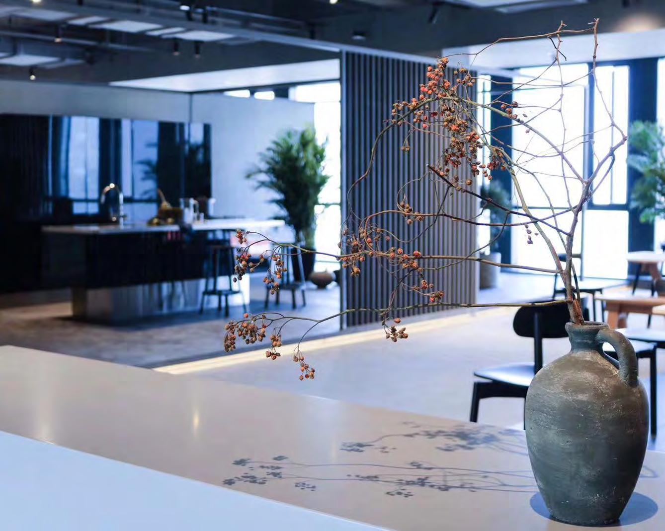
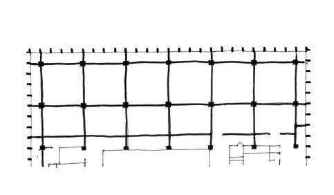
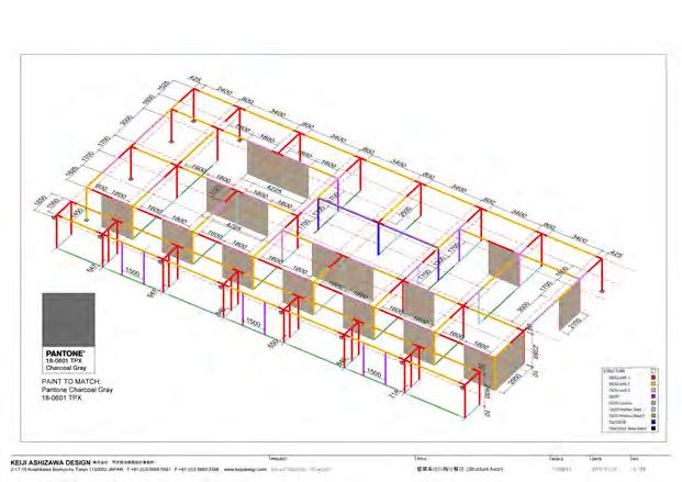
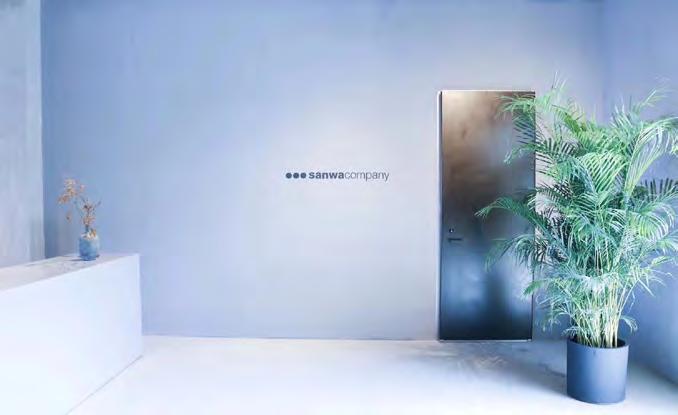
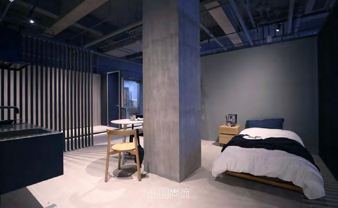
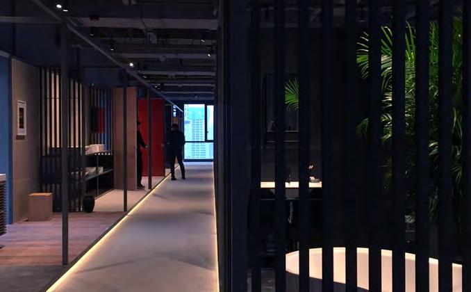
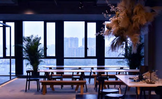
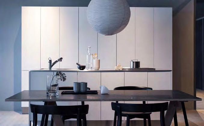
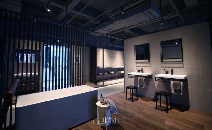
This showroom is based on the concept of a frame within frame. This frame system creates flexible modules which can be reconfigured to show different scenes that showcase the whole range of Sanwa Company’s kitchen and bath products. The intention was to create a showroom that not only displays the products, but showcases new lifestyle possibilities to the Chinese market by introducing Japanese simplicity.
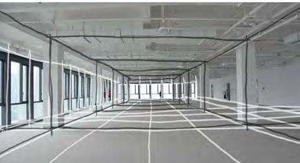
The idea utilizes the structural rhythm of the architectural shell in order tocreate a secondary structural system. This secondary frame system uses a simple dark steel frame and louvre system to create different types of rooms ranging from: compact hotel rooms to luxury kitchen and bath and luxury hotel. The timeline for this project was extremely accelerated, with me and my colleague having to go through schematic design through finished construction in only 6 months.
21
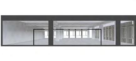
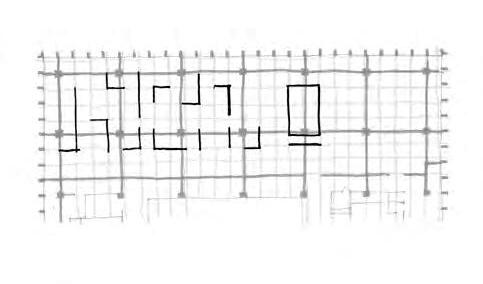
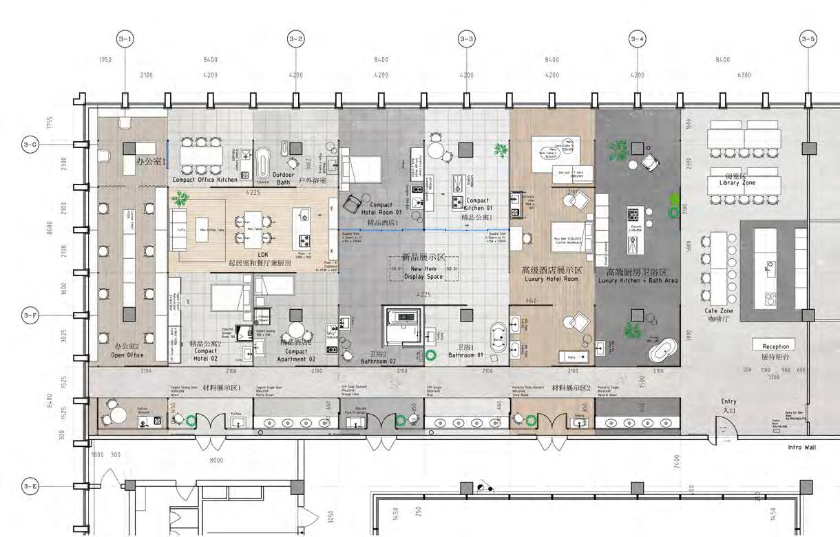
Showroom Plan 1:200
22 Steel Hollow Section 30x50 Quadro Slim Doors (4 Slide) 48 正面 50 50 90 1215 12.5 9 Plywood Base T=18 Plywood Base T=9 50 KEIJI ASHIZAWA DESIGN 株式会社 芦沢啓治建築設計事務所 2-17-15 Koishikawa Bunkyo-ku Tokyo 1120002 JAPAN T +81.(0)3.5689.5597 +81.(0)3.5689.5598 www.keijidesign.com Flat Bar 3x30 Flat Bar 9x90 50 50x50 Steel Hollow Section 9 1215 12.5 3 3 3 正面 4150 15 12.5 9 12.5 2100 2100 2300 4200 4200 44 44 4150 Flat Bar 9x90 Steel Hollow Section 15x15 50x50 Steel Hollow Section Plan View
of Wall Frame Fabrication Details
Detail
23
TOKYU MILAN HOTEL
Location: Shinjuku, Tokyo, Japan
Project Type: Luxury Hotel
Phase: SD and DD
Role: Designer at Keiji Ashizawa Design Co. Ltd
Area: 3000 sq meters
24
05.
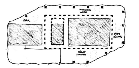
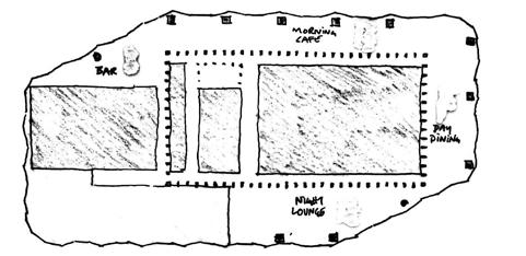
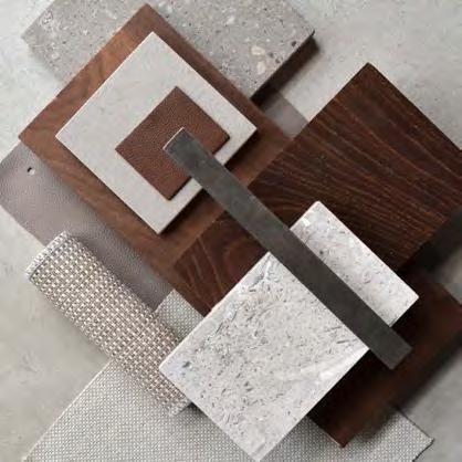
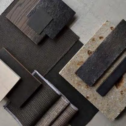
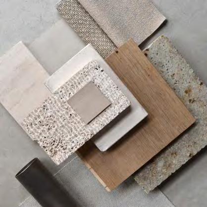
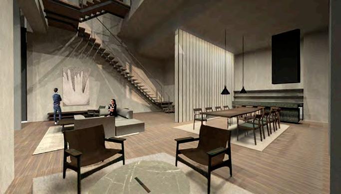
Inspired by the grand architecture of Milan and the restrained, simple and timeless aesthetics of the old Tokyo, Tokyu Milan is a hotel that is conceptually a fusion of the two metropolises. Both cities carry a strong architectural tradition characterized by their columns, rhythms, layers of spaces and a richness of materials.
The ambition is to create a united space with a new expression grounded in the two strong legacies of these two cultures. Implementing colonnades, wooden panels and marble walls washed with light will be of main focus. An evolving change of materials throughout the space will define the different areas and bring out the most delicate details of good craftmanship.
25
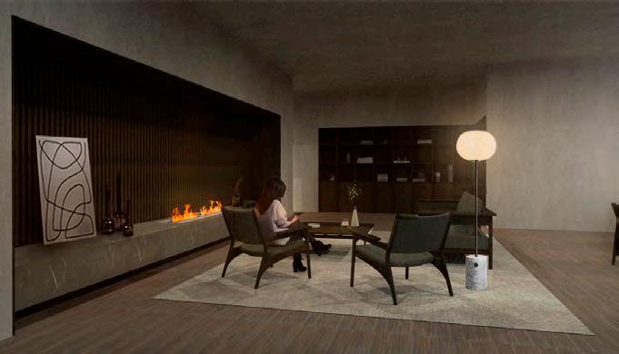
Morning Daytime Evening
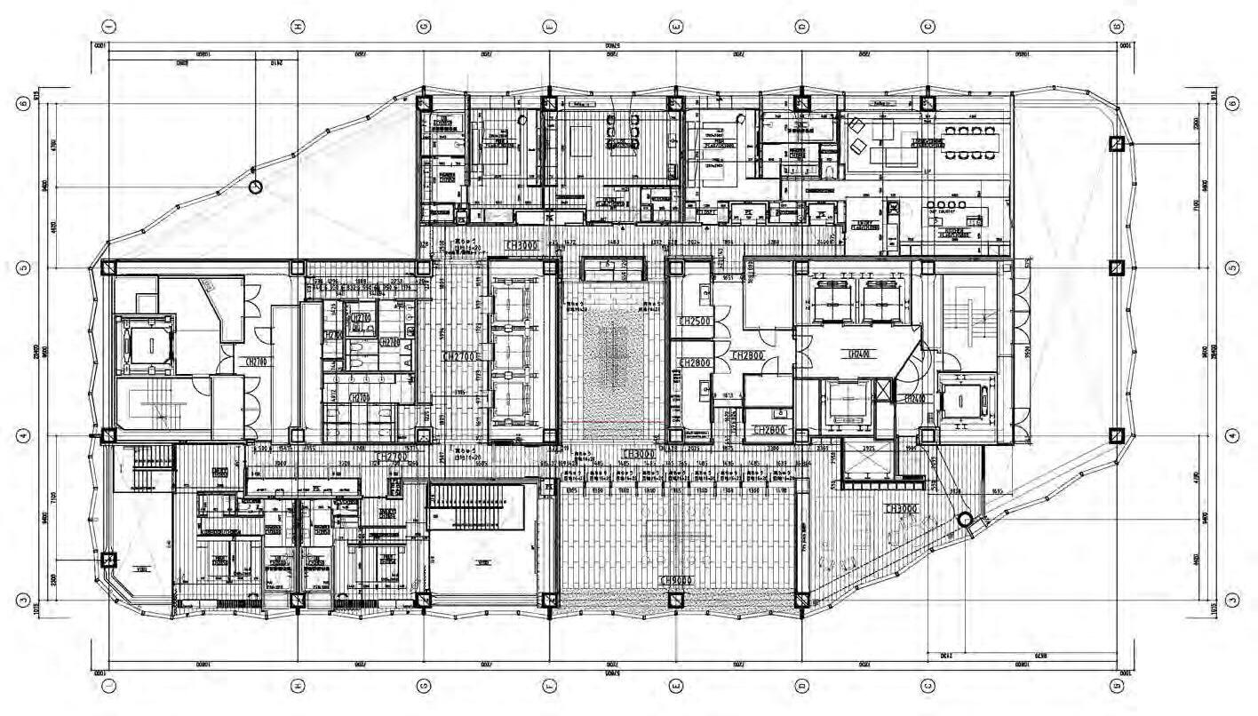
26 41F Plan 1:300
Skygarden
Sunset Lounge
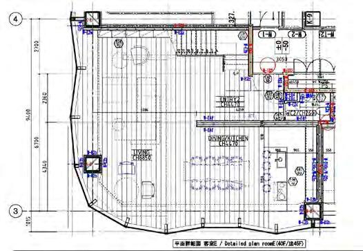 Room E LDK
27
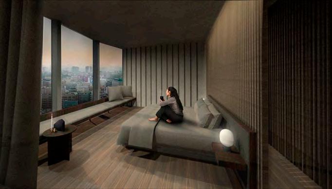
Room D Bedroom
THE SOUL OF NØRREBRO
Location: Copenhagen, Denmark
Award: 1st Prize - Competition Winner, Nordic Built Cities Challenge Winner
Project Type: Landscape Climate Adaption Masterplan
Role: Competition Team Member at SLA Architects
Area: 85,000 sq meters
Projected Budget: 18 million Euro
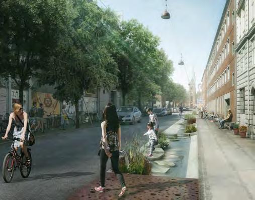
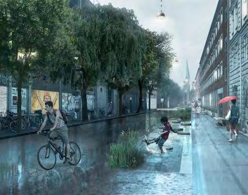
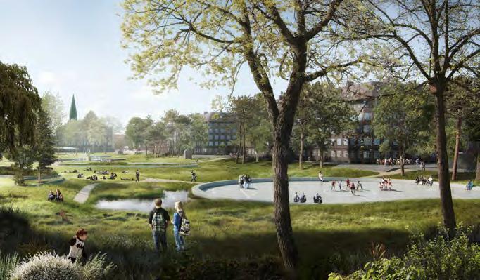
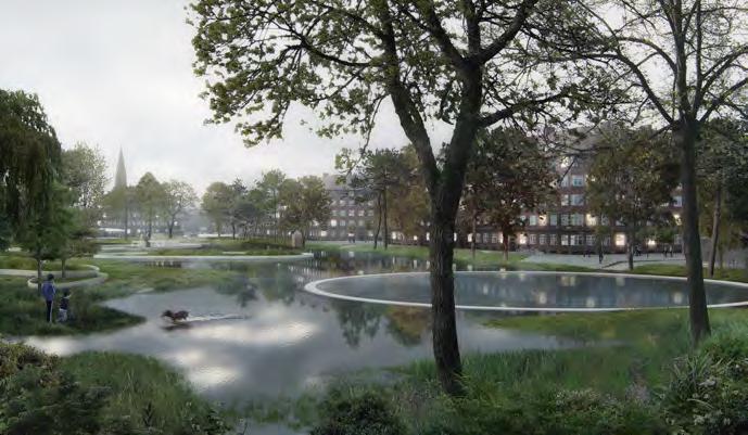
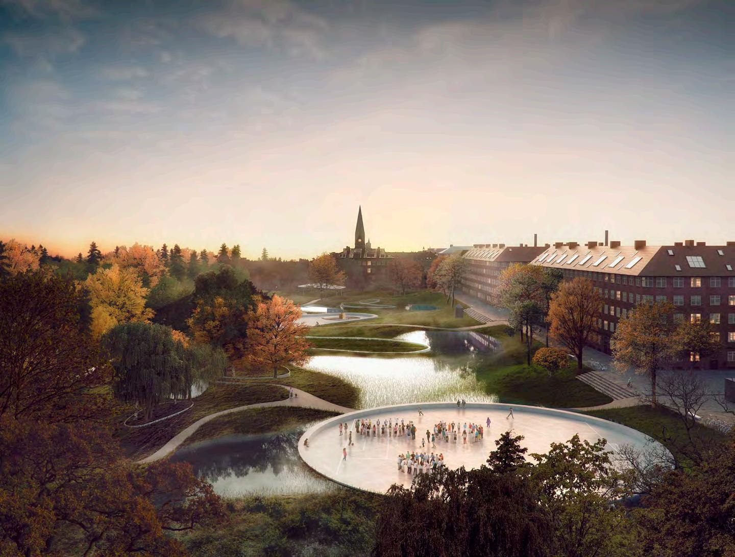
28 07. Rendering by Professional Rendering Firm
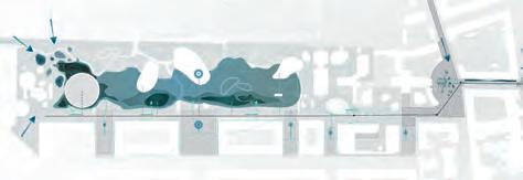
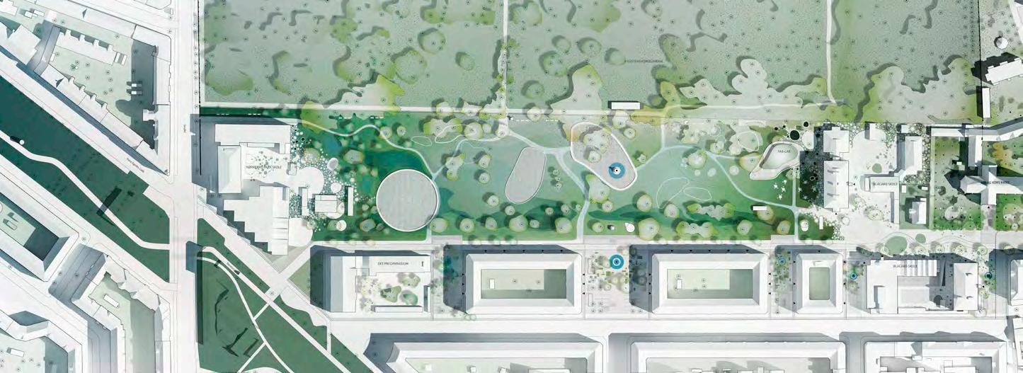
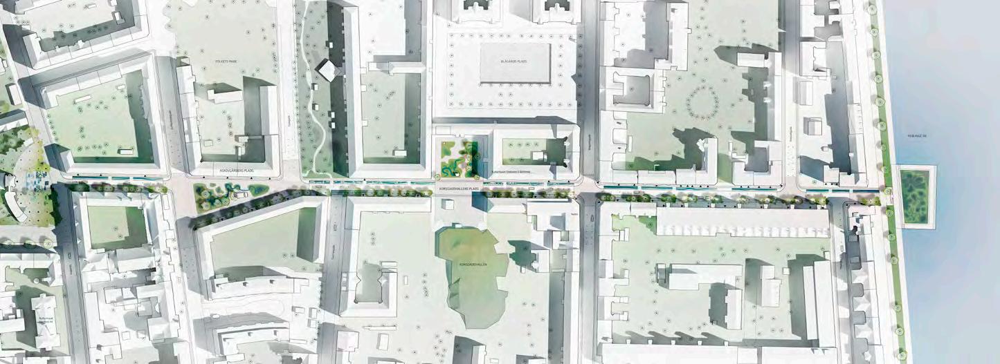
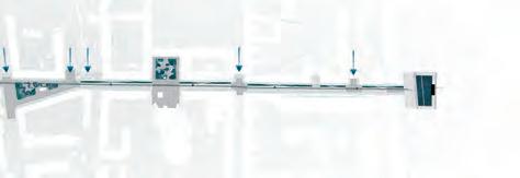
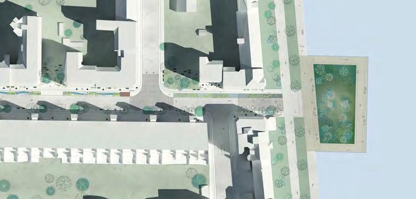
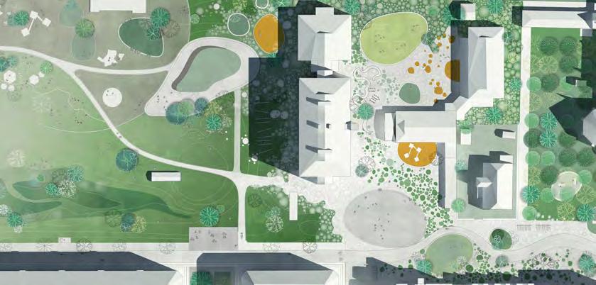
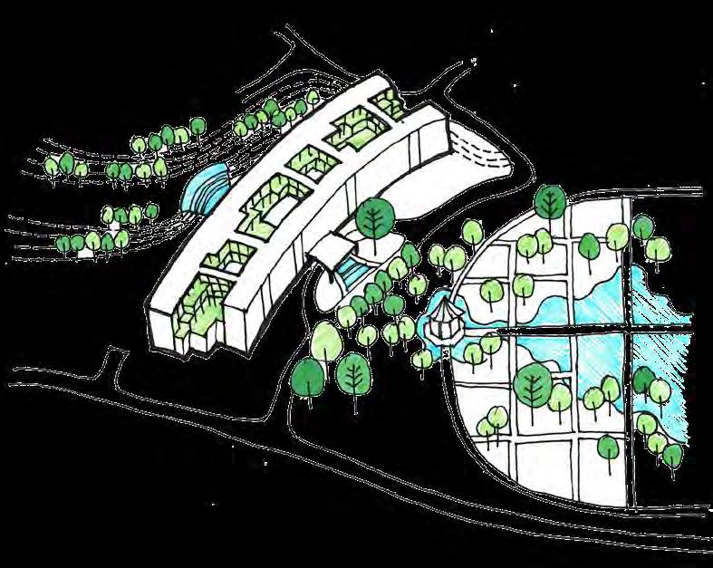
Water, whether the increase of it, the pollution of it or the lack of it will be one of the main urban challenges of the 21st Century. SLA’s project The Soul of Nørrebro addresses this issue through a new Nordic Model for city development. It is a highly scalable model based on co-creation, dialogue and humanistic nature-based design solutions., which seek to simultaneously solves both physical, social and cultural challenges in our cities.
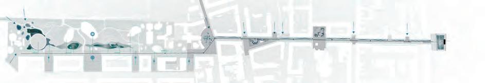
The Hydrological Circuit


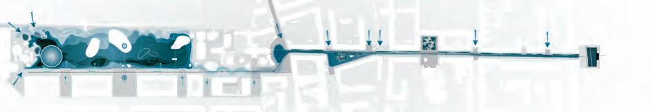
Copenhagen’s city nature needs the utility and amenity values of its rain water – as well as its poetic value. In The Hydrological Circuit both small and large scale rain is seen as a resource where the rain water is collected, cleansed and reused to irrigate the city nature, and to enrich the everyday life in the city with a new poetic and sensuous experiences of life-giving rain.
The Biological Circuit


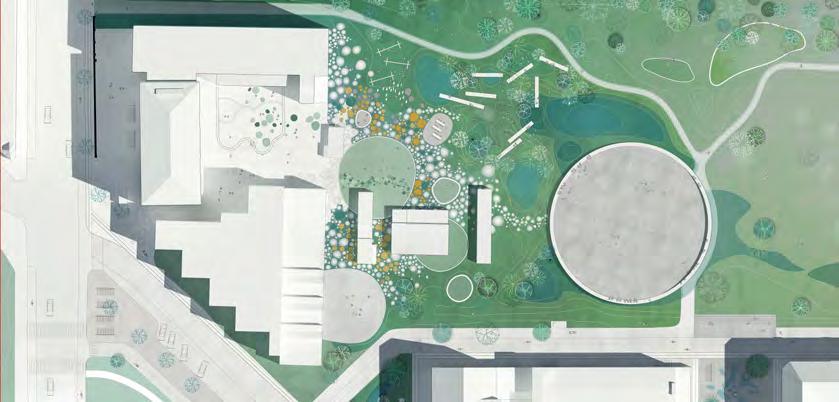
Nature’s biological circuits are vitalizing, dynamic and constantly evolving. By strengthening The Biological Circuit of Inner Nørrebro, Hans Tavsens Park will become the birthplace of a biological diversity and variety that will spread from the area to the rest of Nørrebro and Copenhagen.
The Social Circuit


Nørrebro is the most diverse neighbourhood in Copenhagen. The purpose of The Social Circuit is to strengthen commitment to – as well as the co-creation of – the residents’ shared well-being. The Social Ciruit is anchored in the neighbourhoods’ institutions – including Copenhagen’s first Fablab for City Nature.
CIty Nature.
29
MATURING THE BIRTHPLACE OF DIVERSITY MIXING WEATHERING FLOWERING GROWTH FOCUS ON CO-CREATION PLAYFUL CHILDREN PIONEERING SPIRIT COMMUNICATORS ACTIVITY LOCAL COMMITMENT 100% UTILITY & AMENITY VALUE DELAY & STORAGE RECYCLING RAIN SEEPAGE CLEANSING
ENGAGING ECOTONES : LAGUNA GLORIA
Location: Austin, Texas, USA
Award: 1st Prize - Competition Winner, Consequent Masterplan, Schematic Design
Project Type: Landscape Masterplan Competition
Role: Designer at Reed Hilderbrand LLC
Area: 18 acres / 72,000 sq m
34
08.
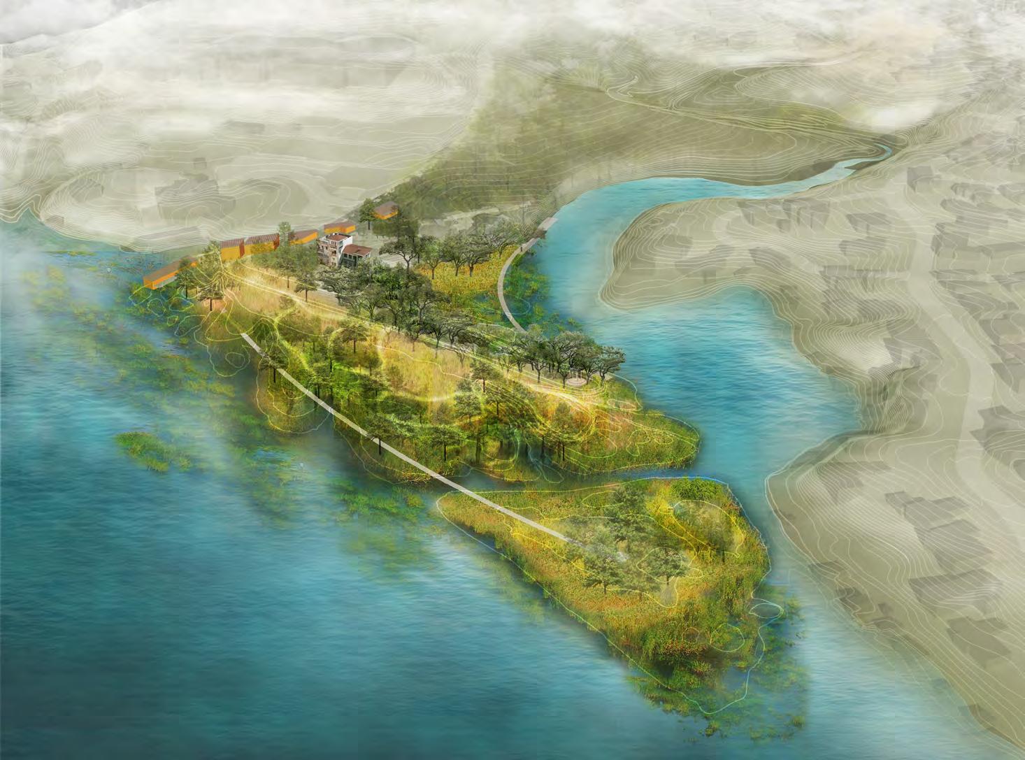
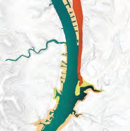
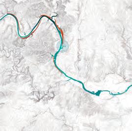
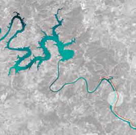
Laguna Gloria is a historic riverside estate in Austin, Texas that was acquired by “The Contemporary Austin” to be the future site for an outdoor sculpture park. Out of four shortlisted landscape architecture firms, Reed Hilderbrand’s competition entry was selected to continue on to the design of the masterplan proposal for the 12-acre site. The waterfront site will be reconceived as a coherent and welcoming landscape that inspires site-responsive permanent and temporary art installations.

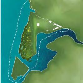
 Colorado River
Lake Austin
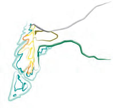
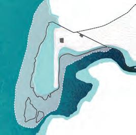
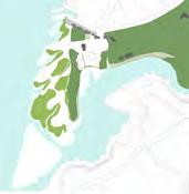
Laguna Gloria Hydrology
Landform / Microtopography Steep Slope Analysis
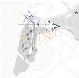
Existing Vistas
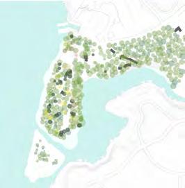
Existing Canopy
Colorado River
Lake Austin
Laguna Gloria Hydrology
Landform / Microtopography Steep Slope Analysis
Existing Vistas
Existing Canopy
35
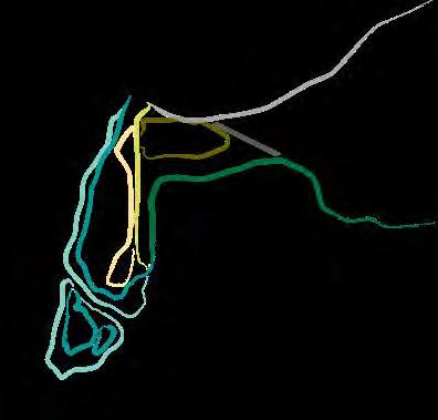
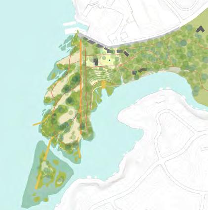
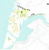
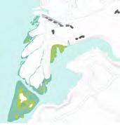
Existing Edges: Static Proposed Dendritic Edges: Dynamic
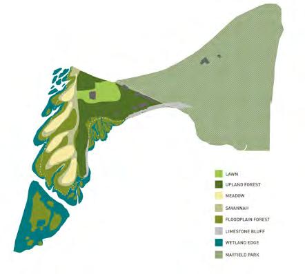
Proposed Ecological Zones
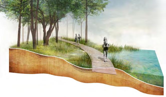
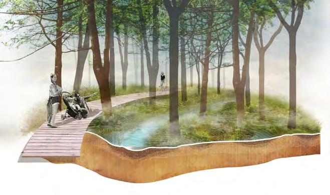
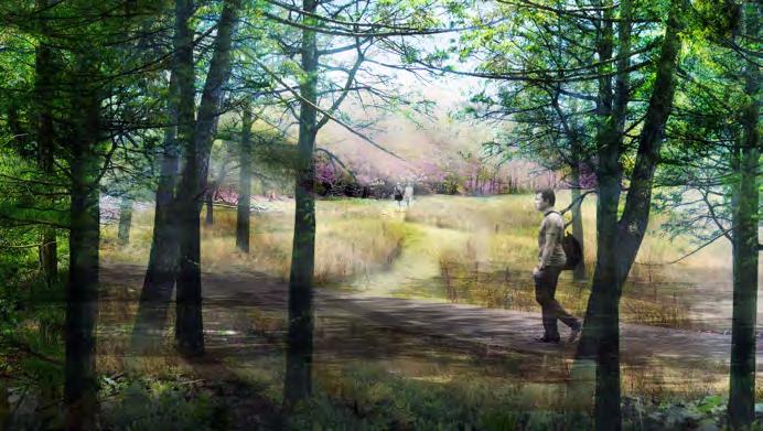
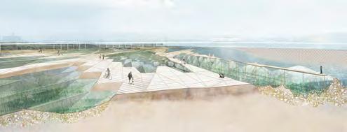
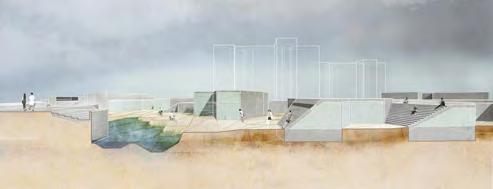
CREATING SPACES FOR ENGAGEMENT

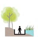
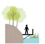
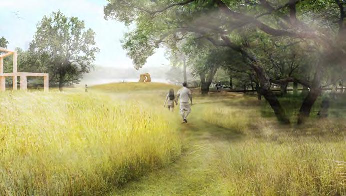
By increasing ecological edges, we seek to create unique pockets of space that make Laguna Glorai a distinct destination for visitors. One key part of hte design was toreconnect the land and water, By creating a unique boardwalk system throughout the site, we wanted to give visitors the opportunity to walk through the various ecological zones to engage with both the landscape and art.
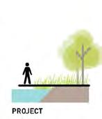
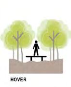
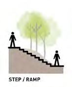
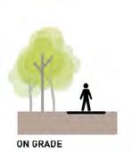
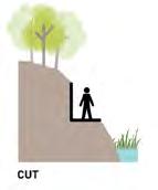
Circulation Typologies:


36
Boardwalk Over Hummocky Wooded Ground
Meandering Emergent Edge Boardwalk
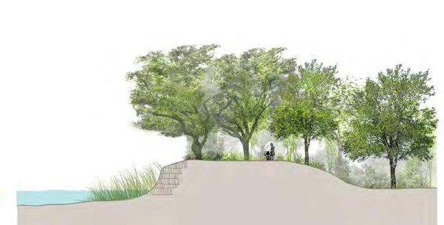
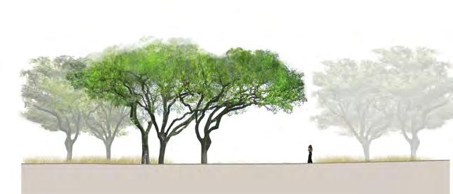
On Grade Meadow Walk
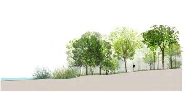
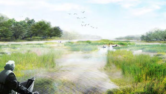
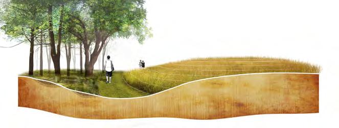
 LOWLAND / EMERGENT EDGE
MEADOW / SAVANNAH
LOWLAND / EMERGENT EDGE
MEADOW / SAVANNAH
37
DENSE WOODLAND
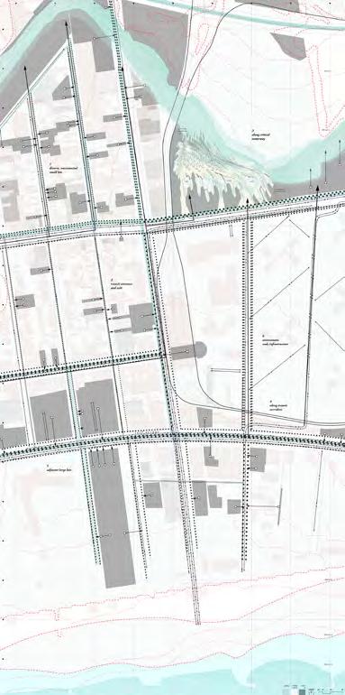
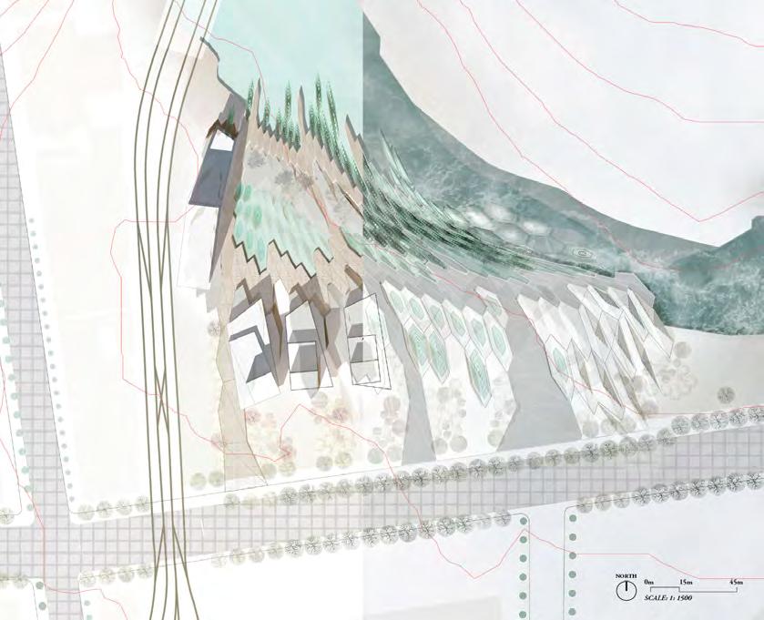
THE URBAN SIEVE
Location: Palava City, Mumbai, India
Studio: Harvard GSD Option Studio - Spring 2017 - Urban/Landscape Design
Professors: Christopher C.M. Lee + Simon Whittle
Area: 35.3 Hectacres
Award: Featured in Harvard GSD Platform 10 exhibit
38
09.
The Palava development seeks to create a world-class “developmental city” – which can create its own self-sufficient digital and immaterial economy away from the messiness of the material-based economy of Mumbai.
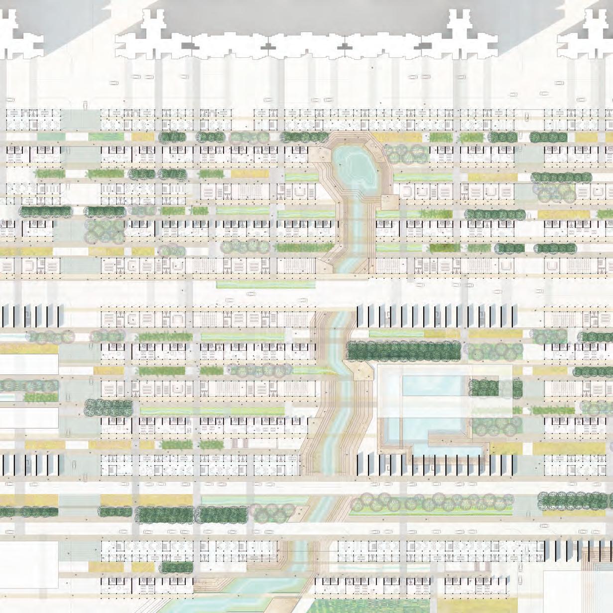
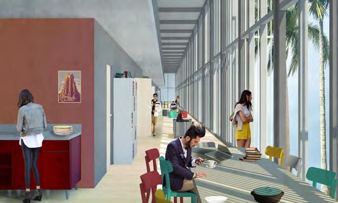
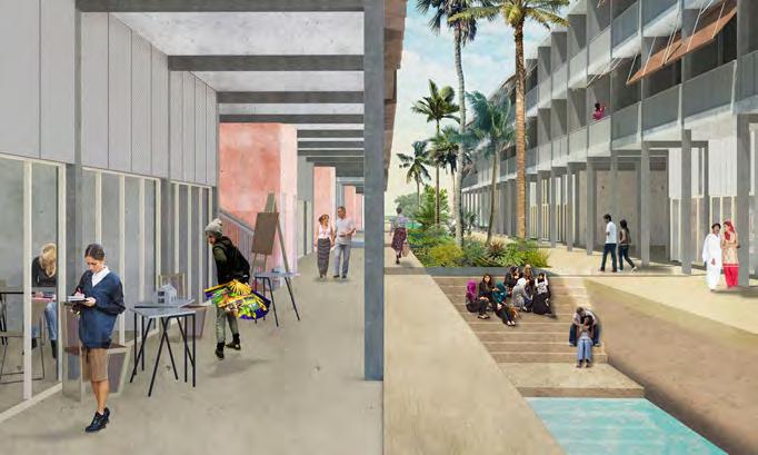
To encourage a new type of knowledge-based live and work urban environment, we are proposing the concept of an urban sieve. This urban sieve’s deep structure functions in a bilateral manner to organize movement. The deep structure that divides the space of economics (the housing units) imprints itself on the ground floor as a flexible, colonnaded corridor. The openness of the ground plane allows people and landscape to filter through. This creates programmatic clarity and continuity in the east-west direction while allowing for a diversity of landscape experiences moving east to west.
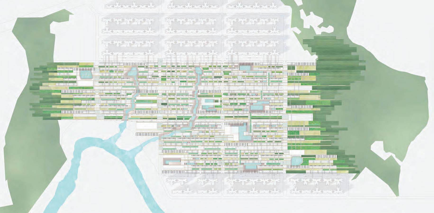
Our “urban sieve” intends to be an intentionally low-rise scheme that disperses the campus across the city within three strips of program on the ground floor: incubator, social/commercial and classroom. Ultimately, the open ground floor plan is meant to encourage the metropolitan condition of chance encounters and unpredictable convergences, conditions necessary for innovation and creativity to occur.
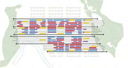
Continuity of Program E-W
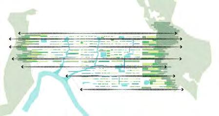
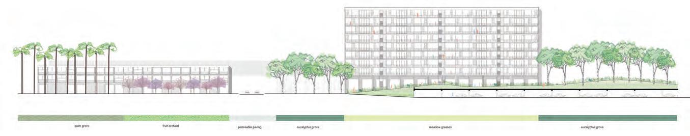
Variation of Landscape E-W
39
40
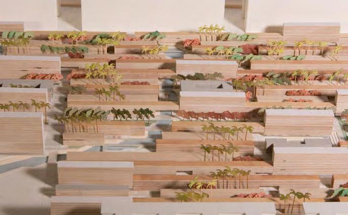
Detailed Ground Floor Plan Centered around Nala Hydrotype
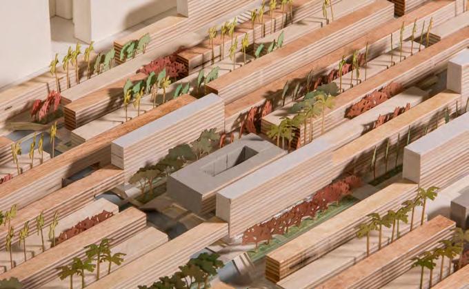
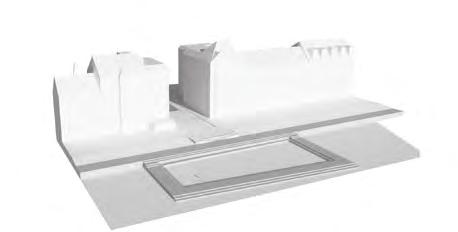
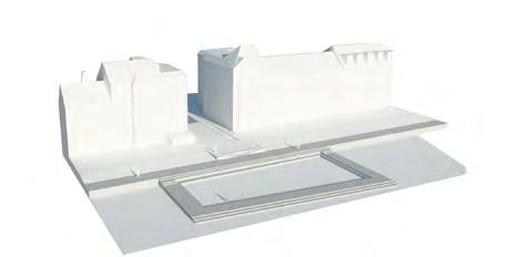
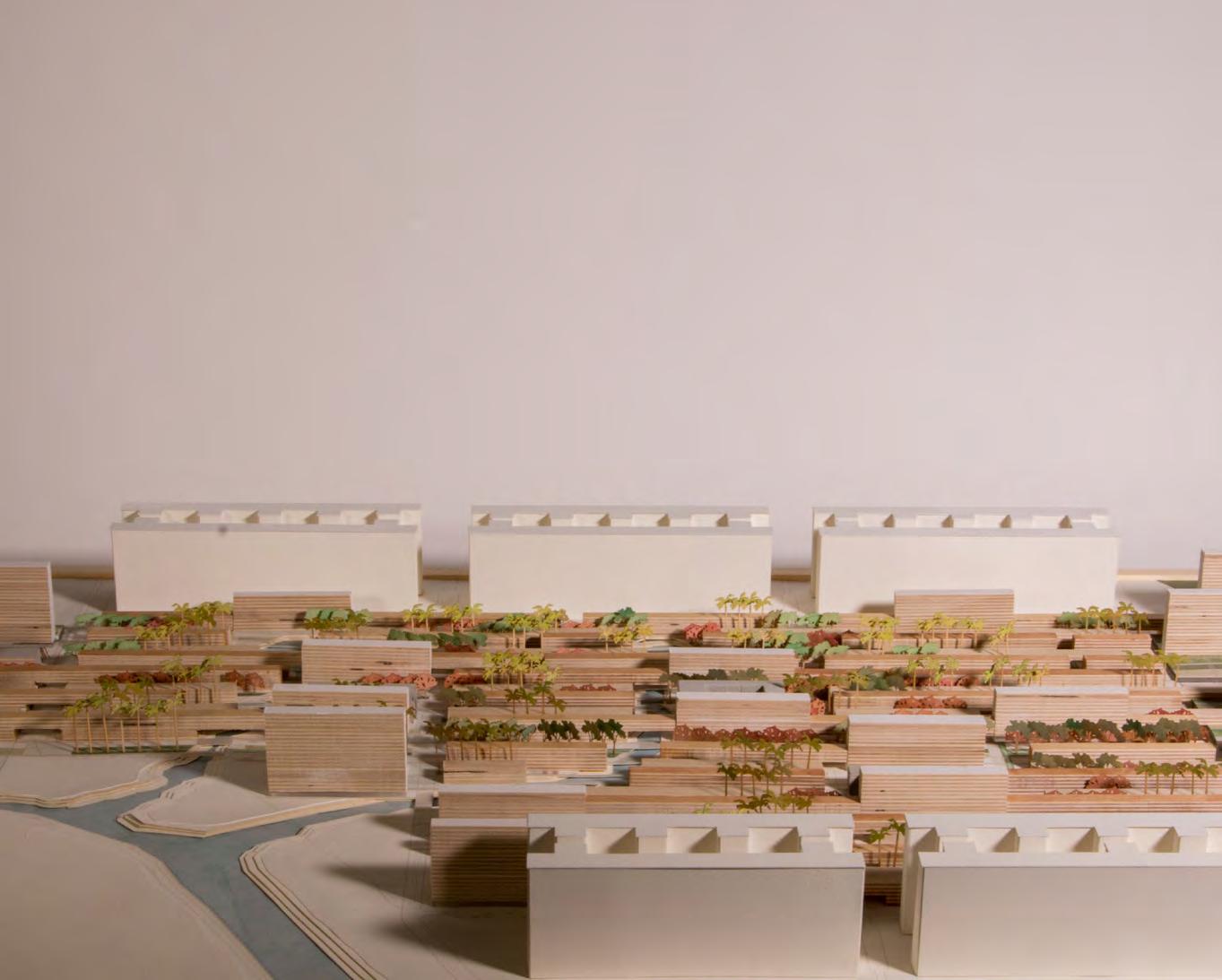
 Massing around a Large Event Space
41
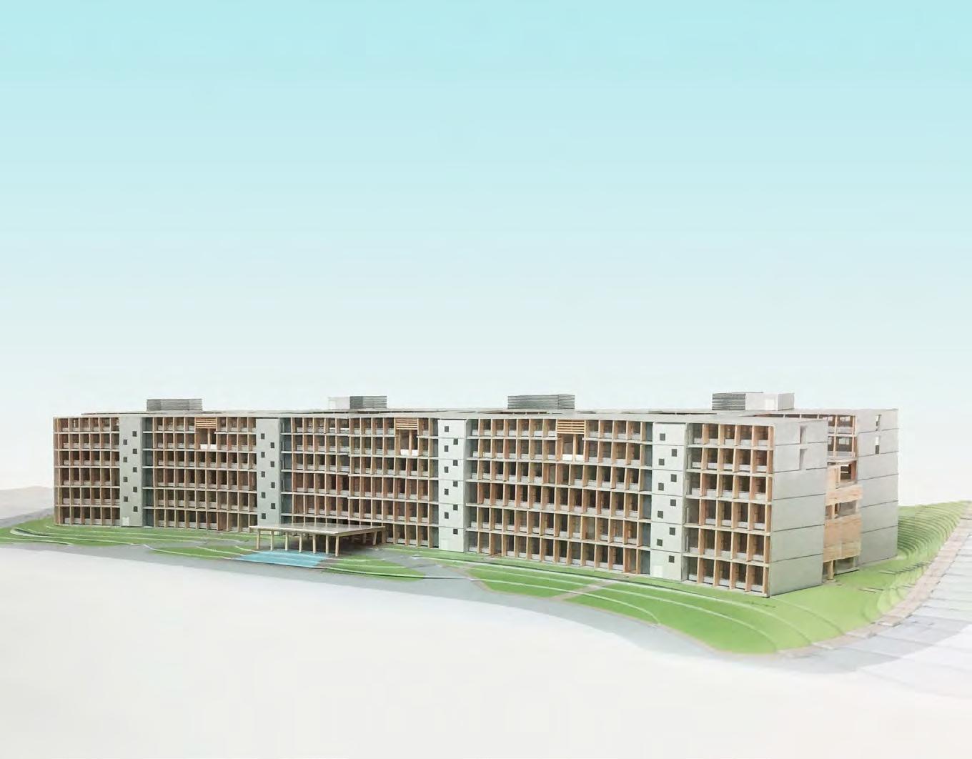
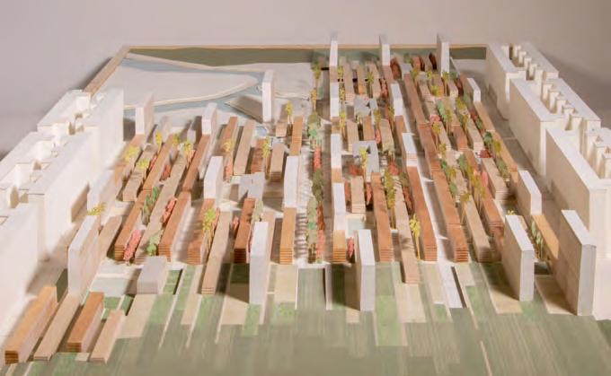
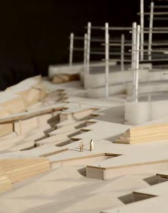
Model of Overall Urban Masterplan Massing E-W Section showing Variation of Landscape Experiences
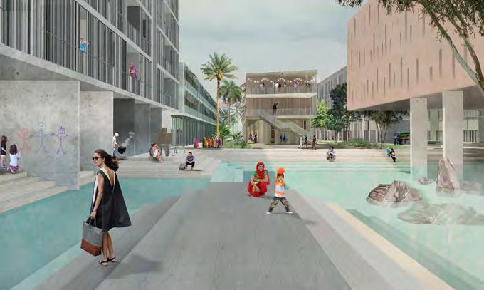
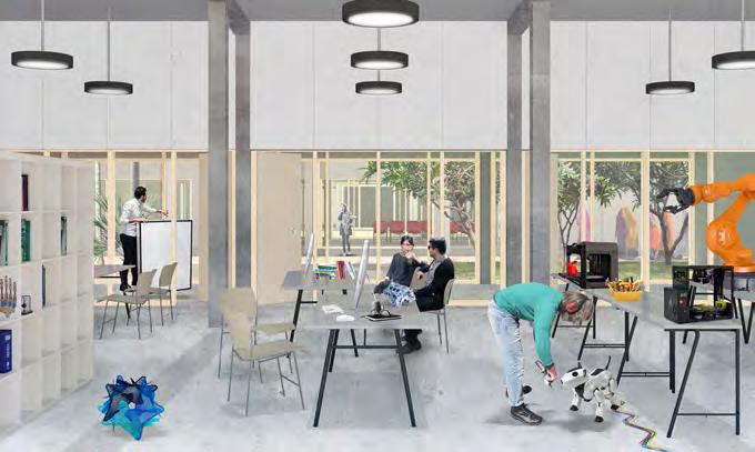
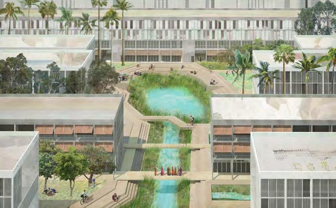
42 Student Housing - Type 1 Ground Floor Level 1 Level 2 Incubator Space Student Housing - Type 1 Large Ornamental Pool Social Space Faculty Housing For-Sale Housing Tower View between Classroom Strip and Social Strip View of Student Housing Shared Common Space Faculty Housing Student Housing - Type 1 Ground Floor 2 Studio Level 1 Level 2 Ground Floor Level 1 Level 2 Student Housing - Type 2 For-Sale Tower Ground Floor Ground Floor Upper Floors Level 1 Level 2 2 Bedroom Unit Studio Student Housing - Type 2 For-Sale Tower Ground Floor Ground Floor Upper Floors Level 1 Level 2
N-S Section Showing Relationship of Strips of Program
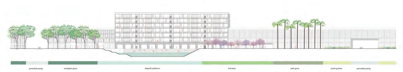
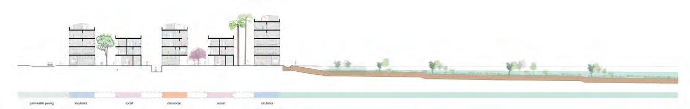
Nala Social Space Deep Stepwell Underneath Pilotis Building Recreational Hydrotype
0M 5M 0M 5M FRACTURED BEDROCK UNCOMPACTED SOIL CHECK DAM WATER LEVEL 20M 20M 0 20M 0 0 1:500 SECTION B 10M 1:500 SECTION A 10M 0M FRACTURED BEDROCK UNCOMPACTED SOIL CHECK DAM WATER LEVEL 20M 20M 0 20M 0 0 1:500 SECTION B 10M 0 1:500 SECTION A 10M 0 E-W Sections along Nala flowing South Check dams along Nalas slow Water
20M 20M 0 20M 0 0 1:500 SECTION B 10M 0 1:500 SECTION A 10M 0 0M 5M 0M 5M FRACTURED BEDROCK UNCOMPACTED SOIL CHECK DAM WATER LEVEL 20M 20M 0 20M 0 0 1:500 SECTION B 10M 0 1:500 SECTION A 10M 0 Ornamental Pool within Bedrock Deep Stepwell Cuts Into Natural Bedrock 43
E-W
Section showing Deep Stepwell Hydrotype
LAND[SCAPE] BANKING
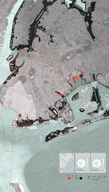
Location: Coney Island, New York, NY
Studio: Harvard GSD Landscape Architecture Core Studio IV - Spring 2015 - Landscape Urbanism
Professors: David Mah + Chris Reed ; Collaborator: Linh Kim Pham
Area: 33,000 sq m
Award: Featured in Harvard GSD Platform 8 Exhibition
44
10.
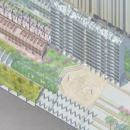
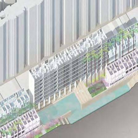
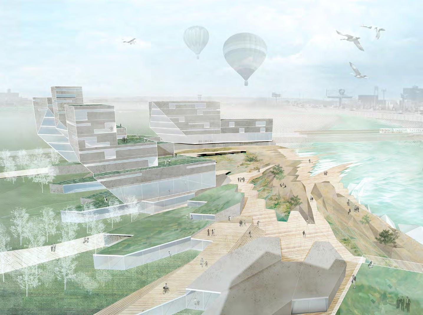
Land[scape] banking puts forth a development initiative that acknowledges the desire to build alongside concerns of coastal vulnerability with an unpredictable building market. With increasingly occurring climatic events such as Hurricane Sandy, this project seeks to create a hydrologic ground work that will guarantee public accessibility in future private development.
Initial Topography Study of Hydrological Ground
Neighborhood Plan of Urban Bioswale Strategy
 Vulnerable Coastal Conditions near Coney Island
45
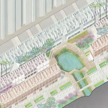
The pilot site was developed in 3 phases. The initial stage establishes a hydrologically performing ground-plane and main bermed path based on the desire lines of water flow and pedestrian movement. This initial ground plane contains landforms that both buffer against storm surge and allow for water to infiltrate the site at certain points.The second phase establishes small scale modular units on the ground floor that will become public retail storefronts. With future predictions of sea-level rise, this public space can become transformed into sacrificial ground for various flood scenarios. The Final phase integrates private development to densify on top of this initial ground floor, first with adapted floorplates and then regularized plates for maximum economic expediency for future developers.
Planting Palette of Hydrological Ground
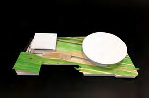
PHASE B low rise retail + bermed topography A

PHASE A Hydrologic landform + urban street network B C
lowland/dune planting upland planting street trees

46
Phase C
Phase B
Phase A
PHASE C densify with mixed use mid-rise building
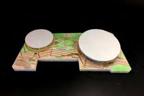
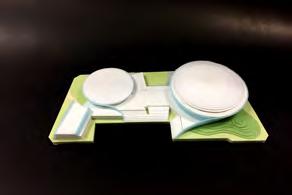
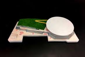
PHASED DEVELOPMENT STRATEGY
Hydrologically functioning ground typologies
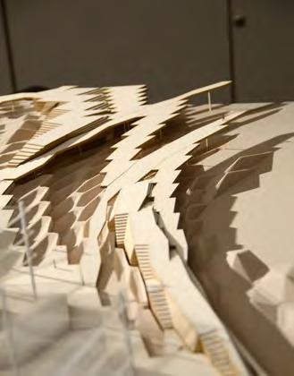


 CNC Routed Hi-Density Foam Model of Phased Development Strategy
Solar Carving
CNC Routed Hi-Density Foam Model of Phased Development Strategy
Solar Carving
47
Model depicting elevated boardwalk + breakwaters