15 minute read
10 Z-Series Keypads

from JVA Z25 Manual

There are 2 different keypads that can connect to the keypad bus of a ZSeries device:
PTE0210 LCD keypad
Advertisement
PTE0230 Touch Keypad Both devices can be used to control, program and monitor the devices on your fence.
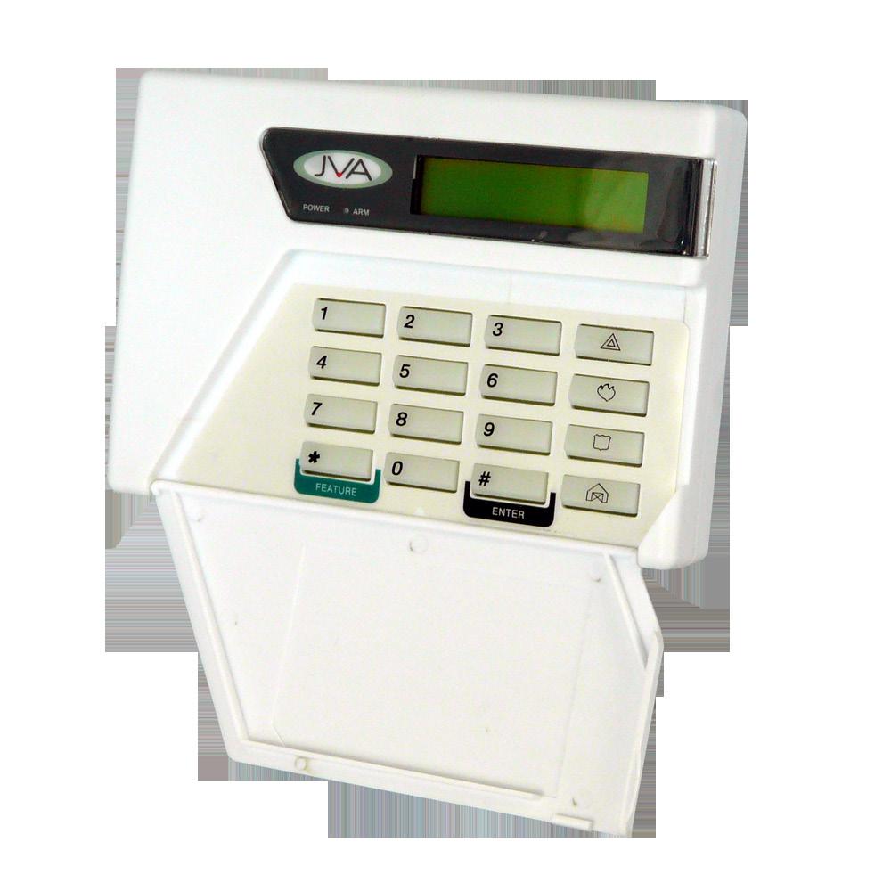
10.1 PTE0210 LCD KEYPAD
Z-Series Keypads
The PTE0210 is an easy to use, durable and economical LCD keypad that can be used to control and program all Z-Series devices. It displays fence information such as fence voltages, battery voltages and any alarms if and when they occur. The onboard beeper alerts the user to any issues and instantly shows the relevant information that the user needs to see.
JVA’s most advanced keypad features include:
Touch screen with clean user interface designed for ease of use
Quickly arm or disarm the entire site or granularly via the Zones screen
Emails on alarm

View all active and latched alarms in the alarms screen Program all Z-Series devices through an intuitive system, without having to remember or refer to a manual for key sequences. With the new MK2 protocol, these devices can be all programmed together without having to isolate each device individually Quiet mode: set a time where the Keypad won’t brighten the screen or set off loud sirens unless it is critical such that you might enjoy a restful night’s sleep. The ability to monitor and log all user actions Can be used to maintain a log on a Perimeter Patrol managed system in case the PC goes down or the TCP/IP connection from the PAE212 to the PC is lost. Note for all information to be captured each sub group will require PTE0230 Touch Keypad
Z-Series Keypads
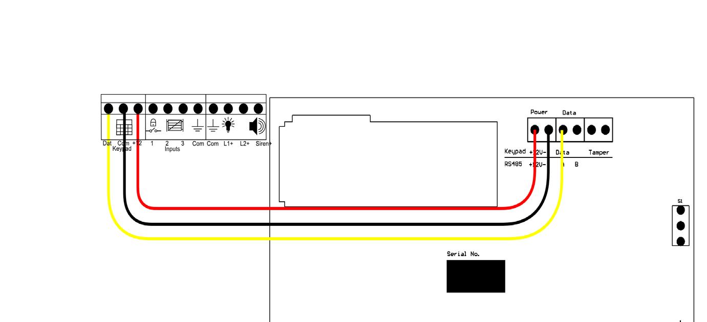
Wiring up your Z-Series LCD Keypad
The following diagram shows how to Wire up a Z-Series LCD keypad.
Z-Series Keypads
Remove the rear of the LCD keypad to expose the wiring terminals shown in the diagram above.
10.3.2 Keypad status LEDs
The LCD keypad has two LEDs, Power and Arm, which act as follows:
Power On with Mains power, flashes on low battery.
Arm On When the energiser is armed (pulsing), flashes when in
Low Power Mode.
Function Arm Disarm
Code [User PIN] # [User PIN] # Default Code 1234# 1234#
LCD Keypad arm/disarm codes. Default code uses the default User pin Enter your [User PIN] and push the # key. Make sure the red ARM light comes on and the keypad beeps twice to confirm that the system is armed. The fence will power up and if all is well (no faults) the system will be ready to deter and detect.
To disarm the system, enter your [User PIN] and press #. NOTE: If there is an alarm sounding you will need to enter your [User PIN] twice, once to silence the alarm and once more to disarm.
10.3.4 Menus
The Z-Series keypad has an optional menu driven interface. The main menu is accessed by pressing the Menu key (bottom right). You will be asked to enter your PIN, and then press #. Most functions are available via the menus. Use the 2 key to go up and the 8 to step down through a menu. The Enter (#) key is used to select the current line.
The menu will time out after a few minutes and return to the normal status display.
Z-Series Keypads
Z-Series Keypads
In normal operation the keypad shows a continuous summary of the system status. For example if the system is disarmed the keypad will display “Ready to Arm”. If the system is armed then the keypad will display the voltages for each zone in the system. Since there can be many things to display the keypad automatically “scrolls” through all relevant information. Each screen is shown for about 2 seconds. If you wish to hold the display at a particular point simply press the # key. The auto scrolling will stop for about 20 seconds. Pressing the # key again will advance the display one step. If a new trouble (AC fail, low battery etc) or alarm occurs, the keypad screen will jump to the relevant zone, the keypad will beep (unless toggled off) and auto scrolling will cease for about 3 minutes.
10.3.6 Changing the Keypad Messages and Address
Function Enter Keypad Programming mode Code [Installer Pin] *01# Default Code 012345*01#
Exit Keypad Program- *# *# ming mode
LCD Keypad Programming mode commands. Default Code uses default Installer Pin
You can change the messages and each of the zone labels. •
The Dealer Message displays when the system is on standby.
Zone Labels displays after the # key is pressed during alarm memory or faults.
The programmable Service Message is displayed during AC failure, communication failure, or low battery.
[4] Cursor left
[7] [5] Next Message [6] Cursor right
[8] Character [0] Last Message [9]
[#] Enter/Exit Emergency not used down
Fire not used
Panic
Bypass not used
Keys used for changing messages To activate the keypad programming mode, enter the [Installer PIN] *, 0, 1, #. Information may be entered into the keypad in the form of letters (upper and lower case), numbers (0 - 9), and 22 special symbols. All characters are displayed in the order: upper and lower case letters, numbers, and special symbols. The [Space] character precedes the letter A. To enter a Label, use the [2] key to scroll through the characters until you reach the desired character. If you scroll past the desired character, the [8] key may be used to scroll backwards. NOTE: The space character is before the A character (When A is displayed, press [8] to get a space). When the desired character is displayed, press the [6] key to move the cursor to the next character position. The [4] key moves the cursor to the left. NOTE:
If you move to the next message using [5] instead of the [#] key you will lose any changes you made!
To change the keypad address, scroll through the messages until the keypad displays: “Keypad address __” then change the value by pressing [2] (up) or [8] (down). Submit the change by pressing [#]. The message order is:
SERVICE MESSAGE (Displayed under “System Trouble”)
DEALER MESSAGE (Displayed under the standby message: “Ready to
Arm”)
ZONE NAMES
Z-Series Keypads
Z-Series Keypads
BAUD RATE (should be left at 2400)
KEYPAD ADDRESS (should be left at 1) 10.4
TO EXIT KEYPAD PROGRAMMING
When you have finished programming, press * #. NOTE: The keypad will also exit the programming mode if you do not press any key within a five minute period. To return the Keypad to default settings press the emergency button
10.5
during power up
CONNECTING MULTIPLE KEYPADS TO A SYSTEM
Function Re-analyse the Keypad group Code [User Pin]*68# Default Code 1234*68#
Up to three keypads may be used to remotely monitor and control Z-Series devices.
To operate correctly, each keypad must be configured to use a unique keypad address. This is best achieved by connecting one keypad (at a time) to the master Z-Series device and updating the keypad address. Once all keypads have a different address, all can be connected to the system. A recommendation is that one keypad is kept at address 1. The Z-Series device now needs to be introduced to all of these keypads. This is achieved by resetting the Z-Series device using the keypad (configured to address 1), by pressing [User PIN]*68#. Alternately the power can also be removed to reset the Z-Series device. After a reset, the Z-Series device will determine what keypads are connected, and only these addresses will be used in the future. This prevents unauthorised keypads being added to the system once it is running. NOTE: If the security system is to use Perimeter Patrol, keypad address 2 should not be used by a keypad because that is the default keypad address that Perimeter Patrol uses.
Zone 1 (the master) must be connected to the group. If it is not connected to the other Z-Series devices in the group, it will not send its data to the keypad; Data such as voltages and alarm information which the keypad displays. If Zone 1 is not connected, the keypad will report a communications failure with all the zones. A Slave Z-Series device that is disconnected from the group will only talk to a keypad if it has a keypad address of 1. When adding or removing a Z-Series device to or from the group, or if you have changed a device ID, be sure to re-analyse the group using the key sequence [User PIN] * 6 8 #. Zone 1 (the master) must be connected to the group for this operation to work. NOTE:
When re-analysing a group ensure all Z-Series device are disarmed; if they are not this function will not work properly. If the group ID has recently been changed you may need to reset, [User Pin] * 6 8 # before the new ID’s will be properly reported to the keypad.
Z-Series Keypads
Z-Series Keypads
The PCB’s will be factory calibrated and should not require adjustment for the life of the product. If, however, certain components are replaced during repair the Energiser may need recalibration. This includes the main processor chip.
Procedure:
1.
On the energiser Fence connectors, connect Return to Feed terminals and Earth (Return) to Earth (Feed) terminals.
2.
Plug in the keypad, power the unit and turn on the energiser using the key-switch. Clearing old calibration using the keypad: 3.
4. Type [Installer’s Code] *, 0, # Enter programming mode. Type 9, 8, 0, 0, # Clear the calibration for the Left value.
5.
6. Type 9, 9, 0, 0, # Type *, #
Clear the calibration for the Right value. Exit programming mode. Once the calibration is cleared, run the energiser and record the actual voltages produced by the energiser using a fence meter. Record the values displayed on the LCD. The actual voltages must be higher than the values displayed on the LCD for calibration to work.
Left Value (Return 1) Right Value (Return 2)
Calculate the return calibration factor (Actual Voltage * 100 / Displayed voltage) – 100 For example If after clearing the calibration the Actual fence voltage is 7.1 but the display left value reads 6.0 (as per the picture above) the factor is:
(7.1 * 100) / 6.0 = 118.3 118.3 - 100 = 18.3 (Ignore the value after the decimal point)
For the Left value, the factor to enter is 18 (an increase of 18 percent). Using the same process for the Right value (above picture shows 5.9kV), For the right value, the factor to enter would be 20. Entering new calibrations using the keypad (for our example) 8.
Type [Installer’s Code] *, 0, # Enter programming mode.
9.
Type 9, 8, 1, 8, # 10. Type 9, 9, 2, 0, # 11. Type *, #. Enter the Left calibration. Enter the Right calibration. Exit programming mode.
Z-Series Keypads
The PTE0230 Touch Keypad consists of the following screens:
Home
Alarms
Settings Events
Zones Zone Details Program Devices
10.8.2 Home Screen
This is the first screen you are presented with when the ZKeypad Application starts. This screen acts as a gateway to all the other screens.
Z-Series Keypads
Key 1.
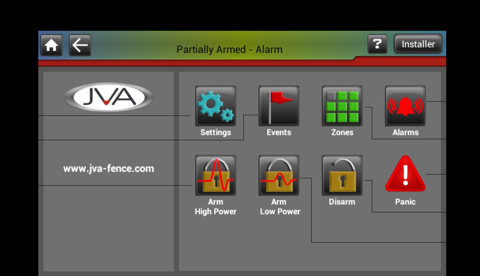
2. Home button – returns you to the home screen. Back button – this will show the previous screen.
3. Site state/alarm screen button – if the keypad is in alarm, launches the Alarm screen, otherwise it shows site information.
6.
7.
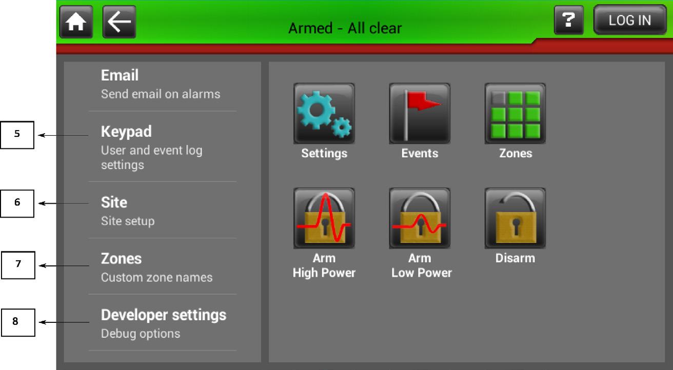
8. 9. Help button – launches the keypad help documentation. Login/logout button – provides pin entry dialog if a user is not logged in. Or if a user is logged in allows them to logout. The above screenshot shows that the installer is logged in. Alarms Screen Button – Launches the Alarms Screen, this will only appear when there are active alarms. Settings screen button – launches the Settings screen.
Events screen button – launches the Events screen.
Zones screen button – launches the Zone Details screen. 10. Site disarm button – disarms the site, privileges permitting. 11. Site high power button – arms the site in high power mode, privileges permitting. 12. Site low power button – arms the site in low power mode, privileges permitting. 13. Panic Button - Pressing this will send the panic command out, activating the sirens.
Z-Series Keypads
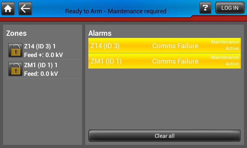
This screen can be accessed by clicking the header bar (where it currently states “Ready to Arm – Maintenance required” in the image below) when the keypad is in alarm or by clicking the dedicated alarms screen button. From within the screen the alarms can be dismissed by clicking the Clear all button. NOTE: The Clear All Button will only clear latched alarms that have been resolved.
Z-Series Keypads
This screen allows the user to adjust preferences such as the screen brightness, zone names and other application preferences
Z-Series Keypads

Key 1.
2.
3.
4. Display – Contains brightness settings. Sound – keyclick and alarm volume settings. System – date and time and Wi-Fi settings. Email – for configuring email notifications for alarms.
Z-Series Keypads
6. Keypad – change user pin, automatic logout time, and event log settings. Site – home screen customisation and site configuration settings – installer only.
7. Zones – allows zones to be renamed, to be more memorable – installer only.
8.
Developer settings – this contains diagnostic information – installer only. Display
Manual Brightness - if checked will enable the Brightness slider allowing you to select the application brightness manually. If unchecked the brightness will be set automatically.
Screen Dims – This option sets the idle time required before the screen dims.
Sound
Keyclick volume – slider that adjusts the click volume that plays when a button is pressed. Siren volume – slider that adjusts the siren volume that plays when an alarm is detected.
Siren mutes – option that allows you to adjust how long the siren will play for before being disabled. System
Set date and time – This option sets the systems date and time
Wi-Fi settings – This option launches the Wi-Fi Settings such that the tablet can connect to a local Wi-Fi network.
These settings allow the tablet to be configured to email up to two email addresses when a fence alarm occurs. This can be configured such that only certain alarms will cause an email to be sent. Keypad
Automatically logout – setting for the amount of time that needs to expire before automatic logout.
Delete events – this option adjusts how many days worth of events are stored and displayed in the events screen. If a Micro SD card has been inserted the device will backup all events to this but will only display the amount of days worth of events selected here.
Show all events – This option toggles whether or not the event log shows all system events or just the important ones.
Quiet Hours - this setting when enabled allows the user to specify a time frame where only the most critical of alarms sound the onboard speaker and brighten the screen. In this way the user can have a good nights sleep and deal with any maintenance issues the following morning. Site - Installer Only
Installer details - by editing this text field you can adjust what is displayed on the home screen under the JVA logo.
Site Name – This setting allows the Site name to be set. This name is used when emails are sent and for the file name when the site is saved.
Clear site - this clears all the devices that are currently in the site.
Save Site – This allows the current sites configuration to be saved to the SD card.
Load Site – This setting allows a site’s settings to be loaded into the keypad without having to configure the site manually. Auto-build zones - by checking this any devices that are added to the site are automatically detected and displayed by the keypad. Program devices – This launches the program devices screen which is explained in further detail below. Keypad id - this is where the keypad id is set. Baud rate - this is where the baud rate is set.
Installer pin - This setting allows you to change the pin required for logging on as an installer. Zones •
This shows all the zones in the site that have been detected by the key-
Z-Series Keypads
pad. By clicking on each zone they can be renamed to something more intuitive to the user.
10.8.5 Events Screen
This screen allows you to view all the events that have been logged by the keypad over the set amount of days set in the keypad settings.
Z-Series Keypads

The zones screen (left) displays the zones that are currently in the site and by selecting one you can find further information about the zone in the zone details screen (Right). In the zone details screen you can set the currently selected zone to high or low power as well as the ability to disarm it.
Z-Series Keypads

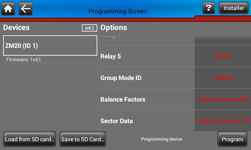
This screen is opened via the Program Devices button in the Site settings. This Screen allows an installer to configure each energiser quickly without having to slowly enter key combinations whilst referring to a manual. If the site energisers are all running the MK2 protocol, you can program each device without having to connect to them individually. To start Programming, choose a device from the list to the left. The Keypad will automatically enter programming mode for that device and read its current programmed settings. These settings will appear on the list to the right. At this point you can begin to edit the settings, upon changing them, their colour will change to red indicating that you have yet to program these to the Z-Series device. To do this, press the program button. After programming the device you may wish to save the currently set up programming options to save time next time. To save the configuration press ‘Save to SD Card’ give the file an appropriate name and press save. You can load this configuration back at any time by pressing the ‘Load from SD Card button’.
Z-Series Keypads
Screenshot above showing when a device is first selected from the left list


Screenshot above showing changed values turning to red
Z-Series Keypads
Screenshot above showing a device that has been successfully programmed


