


















We are getting ready for fall, after a summer of record temperatures, wildfires, floods and water supply issues.
The Calgary Feedermain failure had the attention of many of us in the industry, as the City pulled out all the stops to get the vital pipeline back in service. Several trenchless rehabilitation companies offered potential options to restore water service. It was interesting to observe the wide range of solutions proposed. Perhaps most outstanding was the shipment of two key prestressed concrete cylinder pipe segments from the San Diego County Water Authority.
The pipe failure and resulting solutions really highlighted that we at the NW Chapter, as well as most other Chapters, have a lot of work to do to educate the public and professionals related to infrastructure rehabilitation. The crisis certainly made many aware of the wide range of rehabilitation methods available, and that not all fit every situation.
The NW Chapter has been working on continuing our technical luncheons in Edmonton and Calgary. Keep an eye out for details, and please reach out to our Board if you have any suggestions for topics. We are also planning to introduce more seminars and short courses on a range of trenchless rehabilitation technologies in Winnipeg for fall 2024, and spring 2025. The biggest local Calgary section is planning a two-day symposium for June 2025, which will include a day of NASTT courses and a full day of technical presentations. We have great resources in the Chapter who will share experiences and knowledge through these venues.
Following up our very successful, and attendance record breaking, No-Dig North conference in Edmonton in 2023, the GLSLA Chapter has been working hard to put together excellent technical and overall programs for Niagara Falls, from October 28th through 30th. Registration is open, and a number of individuals from across our Chapter have been awarded municipal scholarships that cover the cost of registration and accommodations for municipal employees to attend the conference. The NW Chapter also contributes towards a
“I call out to any members, as well as other interested individuals, to join us as we strive to provide learning opportunities in Manitoba, Saskatchewan and Alberta.”
number of municipal employees’ costs for travel. These scholarships have historically provided dozens of attendees to learn and network with a wide range of industry experts.
The NW Chapter covers a large geographical area. It makes it
to offer education and networking events. As usual, I call out to any members, as well as other interested individuals, to join us as we strive to provide learning opportunities in Manitoba, Saskatchewan and Alberta. Please reach out to any of our Board members or visit www.nastt-nw.com to learn more about the Chapter and opportunities to learn and grow.
George Bontus, P.Eng. Chair, NASTT Northwest Chapter



Hello Northwest Regional Chapter Members. As we roll into fall, I want to share some key updates and upcoming opportunities that are of importance to your chapter and our organization and industry.
We are so excited for the upcoming No-Dig North conference, scheduled to take place from October 28–30 in Niagara Falls, ON. Th is event is a premier opportunity for professionals in our field to learn about the latest innovations and best practices in trenchless technology in Canada. We encourage all members to attend and take advantage of the technical sessions, exhibits, and networking opportunities. Registration is now open, so be sure to register soon to secure your spot. Visit nodignorth.ca for all the details.
I’d like to offer a big thank you to everyone who participated in this year’s 2024 No-Dig Show held in Providence, RI. Your engagement and contributions made it a resounding success! The presentations were insightful, and the networking opportunities were invaluable. We are currently in the thick of 2025 planning and
“Thank you for your continued support and dedication to your Chapter. Together, we are driving the future of trenchless technology forward.”
we hope you will mark your calendars for March 30 – April 4 in Denver, CO! If you have any feedback or suggestions for future events, please do not hesitate to reach out to us at info@nastt.org.
We are now accepting applications for our municipal scholarship program for the 2025 conference. The NASTT No-Dig Show Municipal & Public Utility Scholarship awards employees of North American municipalities, government agencies and utility owners who have limited or no training funds with a Full Conference and Exhibition registration to the NASTT No-Dig Show. Hotel accommodations are provided for selected applicants. Recipients have full access to all exhibits and technical paper sessions.


The application deadline is November 1, 2024 so please spread the word to any eligible candidates who may benefit from this opportunity. Detailed information about the scholarship program and the application process can be found on our website at nastt.org/no-dig-show/municipal-scholarships. We are excited that the fi fth edition of the Horizontal Directional Drilling (HDD) Good Practices Guidelines book has been released. And by popular demand, the book is now available in a digital format you can access online from any device, as well as a print-on-demand version! The fi fth edition includes updated content reflecting the latest advancements and techniques in HDD. Alongside the book, we have also updated our HDD training course to align with the new edition. These courses are designed to provide both new and experienced professionals with the knowledge and skills needed to excel in their roles. Please check our website for more details on how to purchase the book and enroll in the courses.
Th ank you for your continued support and dedication to your Chapter. Together, we are driving the future of trenchless technology forward. If you have any questions or need further information on any of the topics mentioned, please do not hesitate to contact me.
Best regards,
Matthew Wallin NASTT Board Chair


MARCH 30-APRIL 3 | DENVER, CO







Soil formations with pressurized groundwater is one of the conditions under which horizontal directional drilling is generally considered either particularly challenging with high risk or otherwise infeasible. Maintaining drilling fluid within the borehole is key to the success of HDD. However, the stability of a bore hole is controlled by having the internal pressure plus strength of the mudcake always greater than the external pressure from external soil and groundwater pressure. This paper will focus on the influence of pressurized groundwater causing the external pressure to exceed the internal pressure.
Pressurized groundwater is capable of exceeding the borehole internal resisting pressure. Two conditions are capable of causing this detrimental imbalance: 1) slope drills with one end of the bore significantly higher than the other, wherein the severe change in the borehole elevation along the profile, coupled with the steep nature of the topography and corresponding groundwater elevation contribute to external pressure imbalance at the higher elevation along the bore path and internal pressure imbalance at the lower bore elevations.
2) Pressurized aquifers wherein the groundwater pressure at a point is higher than a typically calculated hydrostatic pressure based on depth below local ground surface resulting in extreme conditions called artesian pressure. Th is technical paper presents the mechanism and key interactions between the drilling fluid, borehole, and groundwater in such situations, along with an analysis of the inherent risks, challenges, and mitigation strategies. Th ree case studies are presented with specific examples of how the risks manifested along with the specific actions taken to address the issues. The case studies document an of encountering an artesian condition capable of generating up to 200 GPM groundwater inflow.
Groundwater flows through soils with a gradient like surface streams and rivers albeit at a much slower rate. The groundwater level within a given soil unit is defined as the elevation of the Groundwater Table. Soil above the Groundwater Table typically is defined as the Phreatic Zone, and has a moisture content of less than 100%
saturation. Soil below the groundwater table often has a moisture content at or near 100% saturation.
An aquifer is a saturated soil unit which stores water and can readily transmit groundwater. Wells advanced into an aquifer will typically produce usable groundwater flow rates when water is withdrawn, groundwater withdrawal causes a pressure gradient resulting in flow within the groundwater which recharges the well. A groundwater withdraw rate that maintains a stable column of water within the well is considered to be the stable withdraw rate for that well. When water is introduced into an aquifer, such as infiltration from precipitation, the water will quickly restore the water pumped from the aquifer. Aquifers are made of soils which are permeable, and typically include granular soils such as sands, gravels, or cobbles, and have relatively small amounts of fine-grained soils.
An aquiclude is a soil unit which does not transmit groundwater flow. The term is often used interchangeably with an aquitard. An aquitard is a soil unit which may transmit a small amount of flow but is considered relatively impermeable over a short time period. Examples of these types of soil units
may include unfractured rock, clay and silt layers, as well as certain very dense and wellgraded glacial soils containing more than about 15% fine grained soil size material (sub #200 sieve size or smaller). Water introduced to an aquiclude will typically not pass through the soil matrix, and often flows along more permeable layers above the aquitard or within an aquifer confined between two aquitards. A confined aquifer can result in artesian conditions when the water has a path to the ground surface.
The groundwater table (Elevation head) in both an unconfined and confined aquifer is defined as the static water level within or above the local ground surface when no drainage is permitted. When groundwater exists in an aquifer on top of an aquitard, and the groundwater table in this layer is higher than the groundwater table in lower soil strata, the water is described as perched groundwater. Perched groundwater is often associated with seasonal water flow. For this paper, groundwater is considered to be pressurized when the groundwater table is higher than the discharge point, such as when a permeable pipe is located below the groundwater table, and artesian when the groundwater table is higher than the local ground surface. Groundwater pressure is defined at the density of water times the elevation changes between the Elevation head and a lower elevation point of interest.
HYDROSTATIC
Hydrostatic groundwater pressure describes a condition where the groundwater table is stable under given conditions. Groundwater flow encounters frictional resistance by the soil particles, which requires groundwater pressure to overcome. Therefore, groundwater pressure at any point within an aquifer with flow is the product of the density of the water times the Elevation head is at the highest point in the aquifer, minus the amount of frictional resistance pressure between the measured Elevation head and the measurement point. The dominant direction of water movement is always from a point of high pressure to a point of lower pressure, with the slope of the water surface defined as the gradient head or pressure gradient.
The gradient for an unconfined aquifer is controlled by gravity acting on the Elevation head at a measurement point, and gradient will trend to slope downhill. The gradient in a confined aquifer will follow a pressure path from the highest Elevation head to a lower discharge point Elevation head that may be above or below the point of highest pressure. The pressure in a confined aquifer
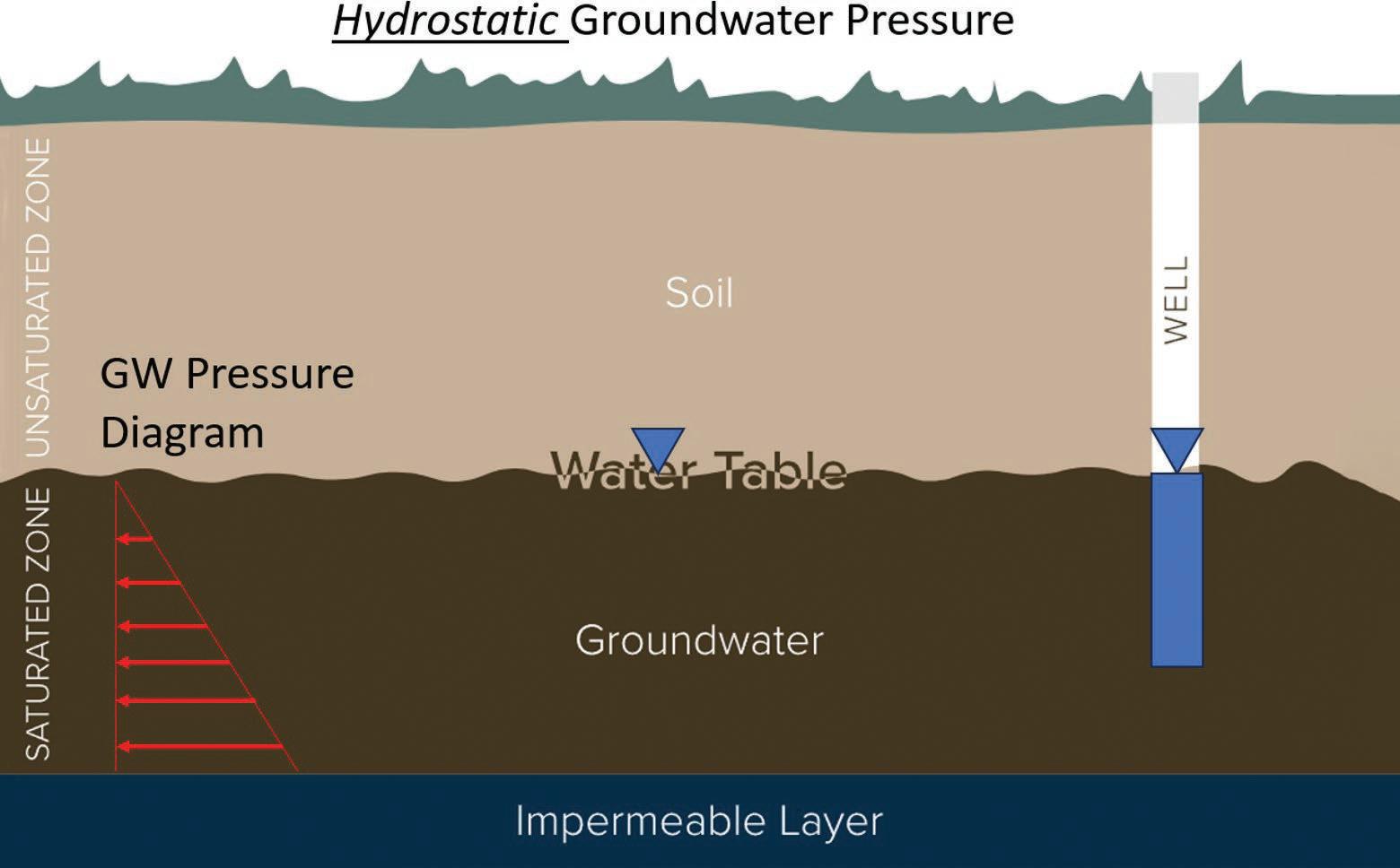
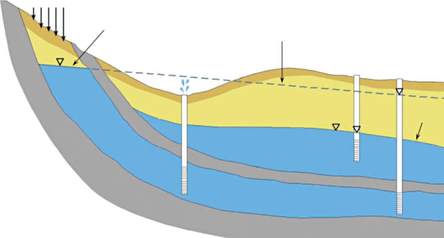
remains the same as for an unconfined aquifer but does not necessarily follow surficial topography. Figure 1 shows a typical presentation of hydrostatic groundwater system with no flow. Under a hydrostatic groundwater condition, a well drilled into the aquifer from above will show a level that is generally consistent with the level of the water within the soil unit.
For this discussion, pressurized groundwater occurs within a confined aquifer. In areas with topographic relief, groundwater Elevation head may build up in a hillside within an aquifer lens of granular soil sandwiched between two clay/silt layers. The aquifer layer may be level but is more often tilted from horizontal. Pressurized water resulting from confined aquifers may be localized in hill and valley provinces, or over a continental area such as the Ogallala Aquifer rooted in the Rocky Mountains and extending well into the Plain States.
Confined aquifers have an Elevation head from recharge to a measurement point of discharge resulting in a pressure gradient within the aquifer. The Elevation head gradient results in a slope or gradient of the groundwater table that is independent from surface topography. Confinement by an impermeable layer prevents the water from seeking a natural (topographically defined) Elevation head gradient as would be expected in an unconfined aquifer. A well advanced into a pressurized aquifer will show a water elevation that is often higher than what would be expected for an unconfined water elevation, as shown in Figure 2.
An artesian condition is a specific type of pressurized groundwater wherein the pressure within the aquifer is such that the hydraulic gradient extends above the ground surface. A well advanced into the soil unit will produce water without active pumping, called out as a flowing artesian well in Figure 2.
HORIZONTAL DIRECTIONAL DRILLING
BENEATH THE GROUNDWATER TABLE
The characteristics of a standard HDD installation have the drill pit and reception pit at the surface, are situated such that the majority of the borehole is below both the entry and exit elevations. The drilling fluid is captured in the ‘belly’ of the drill path at a static elevation head of the lowest pit. The fluid remains static, unless additional fluid is pumped into the bore to cause a pressure gradient resulting in flow from the higher-pressure discharge at the bit to the lower of the pits at atmospheric pressure. Typical unconfi ned aquifer HDD applications have both entry and exit pits higher in elevation than the groundwater elevation. As drilling fluid has a higher density than water, the static mud pressure inside the borehole produces a higher internal static pressure than the local pressure caused by the elevation head. The borehole is stable under this condition. HDD is capable of drilling beneath the groundwater because the internal drilling fluid pressure and mudcake strength
is sufficient to counteract the external groundwater pressure at the impermeable mudcake boundary.
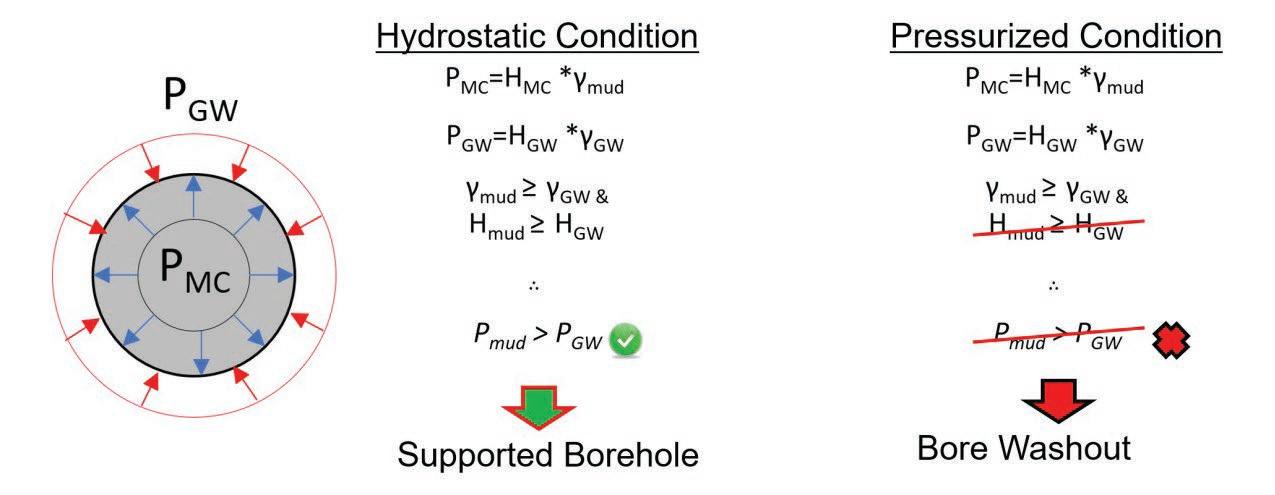
A typical HDD installation beneath a river or wetland encounters conditions similar to the pressure balance model shown in Figure 3 of a Supported Borehole. The properties of HDD drilling fluid when subjected to flow add internal pressure during the pumping process thus improves stability. However, the dominant driver of borehole stability is pressure diff erential between internal and external forces.
There are two sets of general circumstances where the pressure balance shown on the right (Bore Washout) in Figure 3 above is present and fluid will commonly need to be contained in a soil borehole: 1) slope drill wherein the entry and exit are at diff erent elevations, such as the crest and toe of a slope, and 2) instances when the alignment of the HDD advances through a pressurized aquifer where aquifer pressure is greater than the combined drill fluid pressure and mudcake strength.
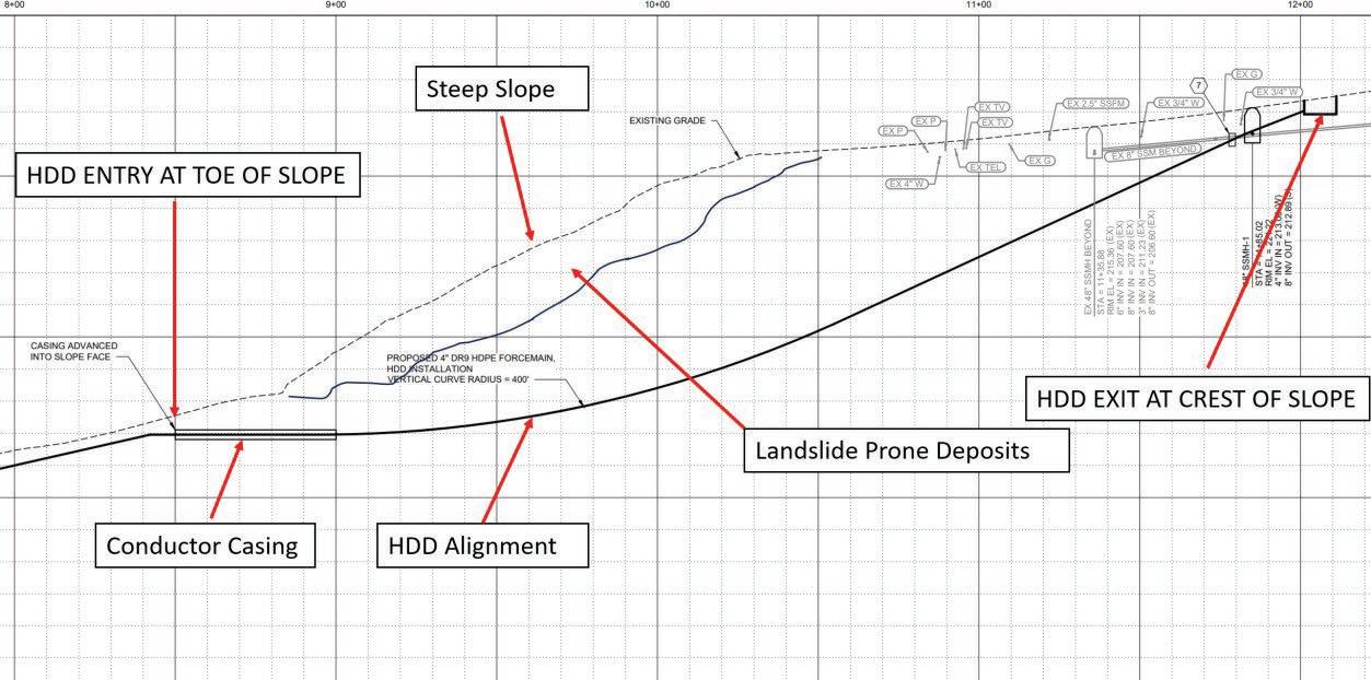
A slope drill describes the scenario wherein the HDD entry and exit pits are at significantly different elevations as described in Figure 4. Typically, the drill rig is staged at the low end of the alignment if at all possible. This convention is due to many experiences demonstrating that drilling downhill will significantly increase the chance for hydrofracture, inadvertent returns, and associated sinkholes as the bore advances downhill. Drilling uphill allows the drilling fluid to flow by gravity back to the drill rig and out of the borehole, but can leave the bore length higher than the entry pit dry of drill fluid, thus providing no support to the bore hole wall by a mud cake and possibly over excavation by erosion as the fluid flows down an unfilled bore hole. Additionally, there is a loss of the lubricating capacity of the drill fluid on the drill rods and during pull back of the carrier pipe adding both friction to the drill string and to the pull force required to install the carrier pipe.
HDD is feasible in dry bore scenarios only in the most favorable of geologic conditions wherein the soils have sufficient strength to hold a hole without internal support, and there are no adverse groundwater conditions to overwhelm the bore path wall.
The following HDD risks are present and enhanced during a slope drill:
1) Borehole collapse: the soils at the crown of the bore fail to bridge and soil collapses into the bore making all phases more difficult and potentially over excavating the bore causing voids/sinkholes.
2) Bore washout: steep slopes often contain perched or perennial groundwater.
The borehole then can serve as a conduit for water to flow, collapsing the bore and over excavating soil. This situation may not be correctable by any mitigation effort and can result in lowering or loss of the perched water in an aquifer. The alignment can travel through competent, impermeable soils and exit into a granular water bearing soil unit that becomes unstable when subjected to the loss of confinement caused by the excavation process (see Figure 3 – Bore Washout).
3) Excessive groundwater ow to drill pit: This is a less extreme instance of risk two above. Even if the water does not fully collapse the borehole, groundwater will flow to the entry pit, dilute the drilling fluid, and overflow the pit. This can result in major costs and difficulties for drill
fluid containment. Any groundwater encountered, whether pressurized or not, typically causes complexity and concern to slope drills because gravity will cause it to flow down any new pathways created by the drilling which can often result in destabilization of the hillside. There are several common reasons why HDD may be applied to a slope drill. To justify taking on the additional risk, complexity, and construction cost of a slope HDD, there should be a strong driver or advantage to using HDD in such an instance.
• Install a new pipeline beneath a hill with surficial landslide prone deposits
• Install a replacement pipeline beneath a hill in which existing infrastructure is failing due to soil movement (easement constrains often apply)
• Hillside is too steep to and inaccessible for equipment to effectively/safely install pipe with open cut/cover without excessive costs and mitigations
• Hillside is regulated or otherwise protected such as a designated wetlands or park property
• No feasible alternative path or construction technique is available.
The most effective risk mitigation for a slope drill is finding and designing the drill alignment within competent soils. Firm to hard fine-grained soils such as stiff silts, glacially overridden fine-grained and wellgraded soils, and soft rock without excessive fractures, are examples of such conditions. If the borehole can be advanced through soils with the strength to bridge over the bore overcut without internal support, every effort should be made to place the HDD alignment within such soils.
Where less favorable soil conditions are exhibited, mechanical or fluid support or ground modification may be required to stabilize the borehole, prevent bore collapse, and allow the HDD installation to proceed. Fluid support is temporary and requires a mud column extending up from the base of the bore to the top. This can be done through the installation of a steel conductor casing and packer installed prior to drilling. A ‘packer’ is a mechanical bushing type of mechanism which allows the drill steel to pass back and forth into the conductor casing and borehole while controlling/ restricting the rate of drill fluid return. Packers used for HDD are often partially
field or shop fabricated. The packer contains valves which may be partially or fully closed to force drilling fluid to build up elevation along the bore path subsequently increasing the internal pressure and providing drill fluid support to the borehole. During the drilling process, sufficient drill fluid still needs to be released to remove spoils from the borehole. This may be accomplished by a careful drill fluid management program and/or more frequent swab or drill fluid flushes of the bore path just for cutting removal.
A packer is also a means of preventing groundwater intrusion from perched groundwater which may be encountered along the design bore path. Uncontrolled groundwater inflow results in an overflowing drill pit and potentially a flooded drill site or contamination of surface waters. The packer allows such water to be contained by closing the valves when there are no drilling activities such as planned shutdowns. Similarly, if the drill encounters perched water in a hillside, the packer is used to prevent uncontrolled volumes of water from flowing out of the hill and into the drill site during drilling, However, it will not stop the long-term flow of groundwater from following the bore path after installation of the pipeline. Such flow may destabilize the hillside, drain the perched water, or destabilize or erode the carrier pipe over time.
A typically situated HDD with entry and exit pits at similar elevations may encounter pressurized groundwater and its resulting complications any time that the HDD alignment advances through an overlying impermeable layer into an underlying aquifer. The effect of pressurized groundwater is particularly noticeable when the elevation
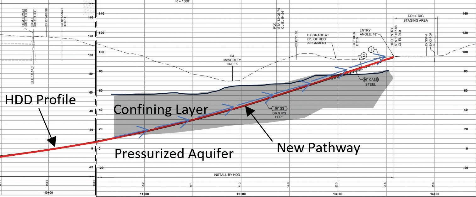
head of the hydraulic contour (level that the water will rise in a groundwater well standpipe) is greater than the local pressure caused by groundwater table elevation head. In such instances, the HDD may create a preferential flow pathway connecting the pressurized zone to the surface pits and to overlying soil units. The fluid will flow to the entry and exit pits, and depending on the pressure and surface topography, the pressure may force the fluid to the surface through more permeable overlying units. The geologic and topographic conditions required to pressurize an aquifer are particularly likely when drilling beneath a steep hill such that the ground surface at the entry or exit is significantly lower than the intervening hill’s topography and geologic stratified conditions. A bore path initiated from valleys or basins or valley aquifer may be connected to a hillside geology that has a distant elevation head differential from the bore, even if there is no elevation difference in the immediate vicinity of the installation.
A common presentation of pressurized groundwater impacting an HDD borehole is shown in Figure 5.
Without planning and design, pressurized groundwater or lack of internal drill fluid destabilizes the bore as external pressure exceeds the internal pressure. Long term and construction related consequences include: borehole destabilization, washout, unplanned settlement, long term dewatering of an aquifer, and hillside instability. External groundwater pressure may exceed the internal pressure and mud cake strength, allowing water intrusion and subsequent over excavation to occur. Groundwater migration along the borehole will displace drilling fluid, remove mud cake, and flow into the drilling pit, diluting the drilling fluid and potentially overflowing containment and the work area.
MANAGING PRESSURIZED GROUNDWATER
Project 1 –1,350 LF of 16-inch HDD with Pressurized GW
Project 1 General Description
Th is installation was designed and constructed in Des Moines, Washington as an HDD to install a 16-inch outer diameter HDPE pipe as a sewer siphon. The installation was relatively deep, up to 120 feet (36.58 metres) below the entry and exit pits, which were at similar elevations.
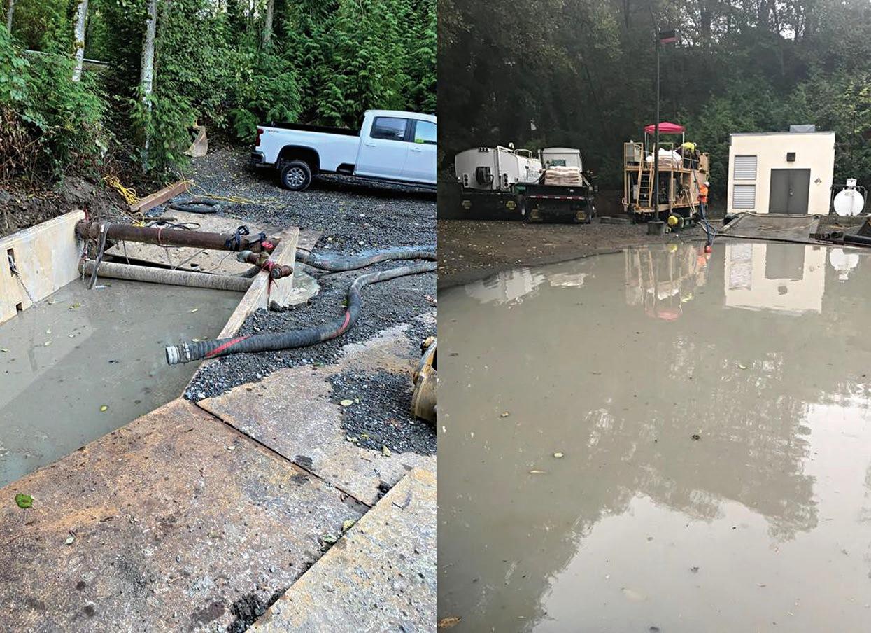
The HDD was drilled from right to left along the pathway shown in Figure 6. The pilot bore extended approximately 200 feet through dense, silty sand glacially overridden soils. The drill bit was a standard hard ground, mill-tooth, tri-cone pilot bit. The drill then encountered a significantly harder layer which required a tri-cone outfitted with carbide button bits. The drill was advanced to approximately 80 feet (24.4 metres) below the drill entry, approximately 250 feet (76.2 metres) into the borehole when operations were stopped at the end of shift on a Saturday. No indication was observed of encountering an aquifer. The following Monday, it was discovered that the drilling pit had filled and was overflowing to flood a low point within the site work area (Figure 7).
Project 1 Groundwater Flow Mechanism
As the construction progressed, it was discovered that the groundwater flow did not stop while draining of water, but rather stayed consistent, suggesting that the aquifer was readily recharged. The hydraulic contour (elevation head) was estimated at approximately 10 feet (3 metres) above the ground surface at the HDD entry area. The inflow of groundwater into the pit varied depending upon the fluid level in the pit, but generally contributed as little as 5 gallons (18.9 litres) per minute and up to 50 gallons (189.3 litres) per minute.
Various glacial soil units were identified in the geotechnical borings including:
• glacially overridden till consisting of various compositions of hard, low plasticity silt and silty sand
• advance outwash consisting of gray/ black gravelly sands and sandy gravels with less than 20% fi ne grained material

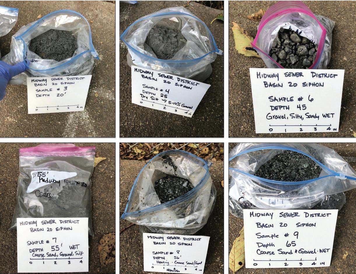
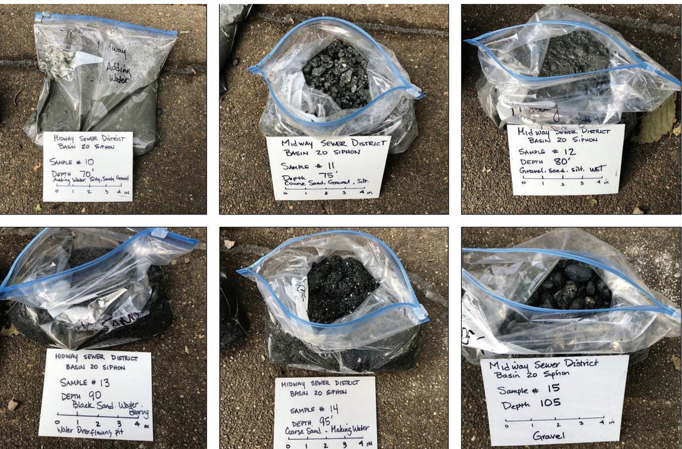
A depressurization well was eventually advanced into the advance outwash aquifer to a depth of 105 feet (32 metres) below grade, providing a cross section of the confining and water bearing layers from which samples are shown in Figures 8 and 9.
The silty sand and sandy silt glacial till layer from approximately 20 to 30 feet (6 to 9 metres) and the combination of gravel, coarse sand, and silt up to approximately 80 feet (24.4 metres) below grade comprise the very dense glacial cap. Below 80 feet depth, a 25-foot-thick (7.6 metre) layer of black sand was encountered and was identified as the pressurized aquifer.
The primary disruption to the work was the dilution of drilling fluid and production of bentonite-laden nuisance water during off-shift hours. During the active drilling of the pilot bore, the presence of bentonite drilling fluid within the borehole, combined with pressure gradient generated by the pumping of drilling fluid, was sufficient to mitigate the intruding groundwater and operations were able to proceed without noticeable disruption.
When the mud column in the borehole was static, the external pressure was sufficient to overcome the internal drill fluid pressure and mudcake strength which allowed groundwater flow to the drill pit. This was a significant delay to drilling operations each shift as approximately 7,200 gallons (32,731.9 litres) migrated to the drill site during each 12-hour nighttime shutdown. Diluted drilling fluid needed to be removed and new mud mixed at the beginning of each shift, slowing production significantly.
Pit pumps were used to direct diluted drilling fluid to settling tanks and from there into a nearby pump station sump.
Th is still required replacement of drilling fluid regularly because it did not stop the displacement and dilution of the bore mud column. The pilot bore was completed in this fashion.
Prior to fi nishing the fi rst ream pass, a depressurization well was advanced into the pressurized aquifer. The target was to depressurize the water and reduce or eliminate groundwater inflow into the bore path while removing ‘clean’ groundwater for ease of disposal. Th is was accomplished and the water was pumped out at a rate of 200 gpm (757 l/m) and was permitted to be discharged into a nearby storm drain.
The water migrating back to the pit halted soon after the well began producing water, thereby eliminating the problems associated with intruding groundwater such that the reaming and pipe pullback could commence using standard means and methods.
The 16-inch outer diameter HDPE pipe was installed into a 24-inch diameter reamed borehole per standard HDD practices. HDDs are commonly left in this manner with the bentonite drilling fluid is expected to eventually mix with drilling spoils and the surrounding soil. This is not sufficient for boreholes intersecting pressurized groundwater, because the borehole acts as a preferential flow path. Upon abandonment of the well, the pressure in the aquifer was expected to return and would then constantly flow along the pipeline, likely eroding the foundation of the pipeline and potentially causing issues in the area surrounding the pump station at the HDD entry area.
The selected mitigation was that the borehole must be sealed within the zone of the confining layer to effectively return the ground to the pre-existing conditions.

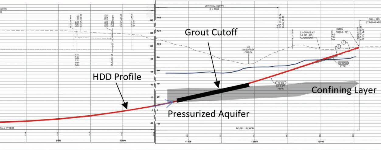
Sealing material placed only in the near surface portion of the borehole or controlled density fill poured into the drill pits may form a short-term water cut-off by stopping water from migrating back to the entry location. However, over time there is a high risk of the groundwater migrating to the surface (because this soil is not necessarily impermeable) causing long term issues with the pipeline, flooding overlying areas, and changing the region’s groundwater regime. Additionally, bore seals must be done remotely from the entry and exit location thus there is no certain method to verify that the long-term seal will be accomplished when sealing a drill fluid filled bore hole.
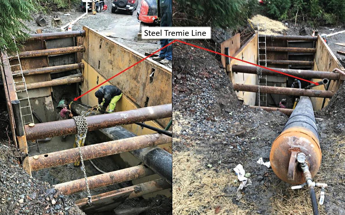
Installing such a grout cut-off is not a simple task within an HDD borehole. Any annular space grouting effort faces challenges because the borehole is not a straight, open cylinder into which grout will readily flow; but rather a void space within the soil filled with water, drilling fluid, drill spoils, and collapsed soils. Therefore, grout cannot be reliably placed from the surface, it must be placed by tremie pipelines installed into the borehole. The installation of these tremie pipelines can be difficult depending upon how clear the borehole and there is often uncertainty in the feasibility of installing the grout pipes any meaningful distance into the borehole, and there is further difficulty advancing past the point of curvature in a borehole.
For this grout seal, a 15 ppg (1,797.4 g/l) heavy grout mix (22 sack neat cement) was used with no aggregate, and viscosity reducers and cure retarder incorporated, to make the mix pumpable and workable during the timeframe allotted for pumping. The weight was chosen to ensure that the mix would easily displace the spoil laden drilling fluid (11 ppg or 1,1318.1 g/l).
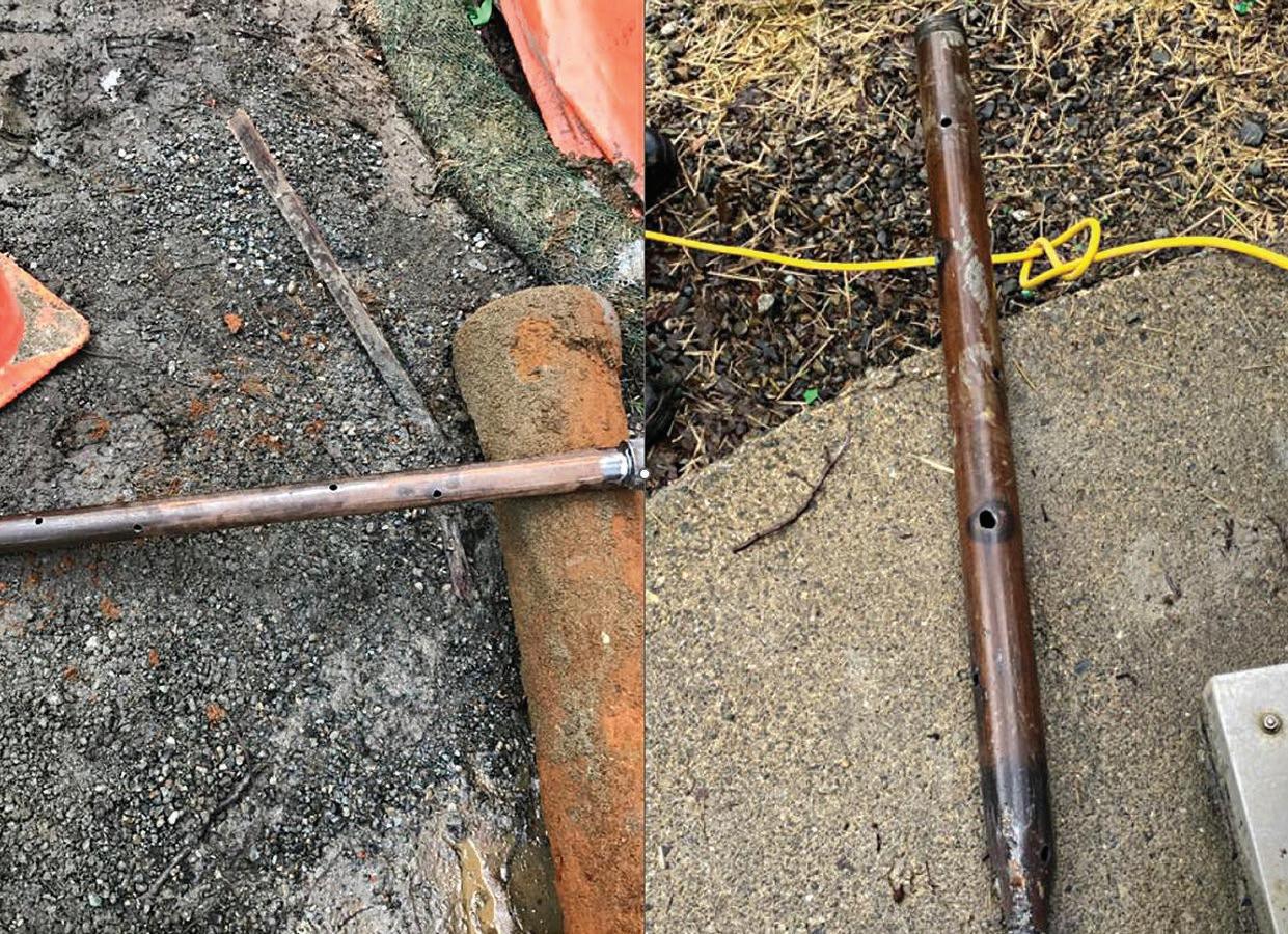
The grout was pumped via two-inch diameter threaded steel tremie pipe on both ends of the borehole (Figure 12). A grout shoe was manufactured in a four-foot length of pipe with 12 x 3/4- inch holes for the grout to discharge into the borehole (Figure 13).
The tremie pipelines were installed 100’ (30.5 m) past the exit pit face into the borehole and approximately 200’ (60.1 m) past the entry pit face. The entry pit was considered the most critical as it was
clear that the topology and geology were such that groundwater would return to this location under restored conditions. However, if the confining layer extended along the alignment the exit side of the borehole was also a potential opening through which pressurized groundwater could flow.
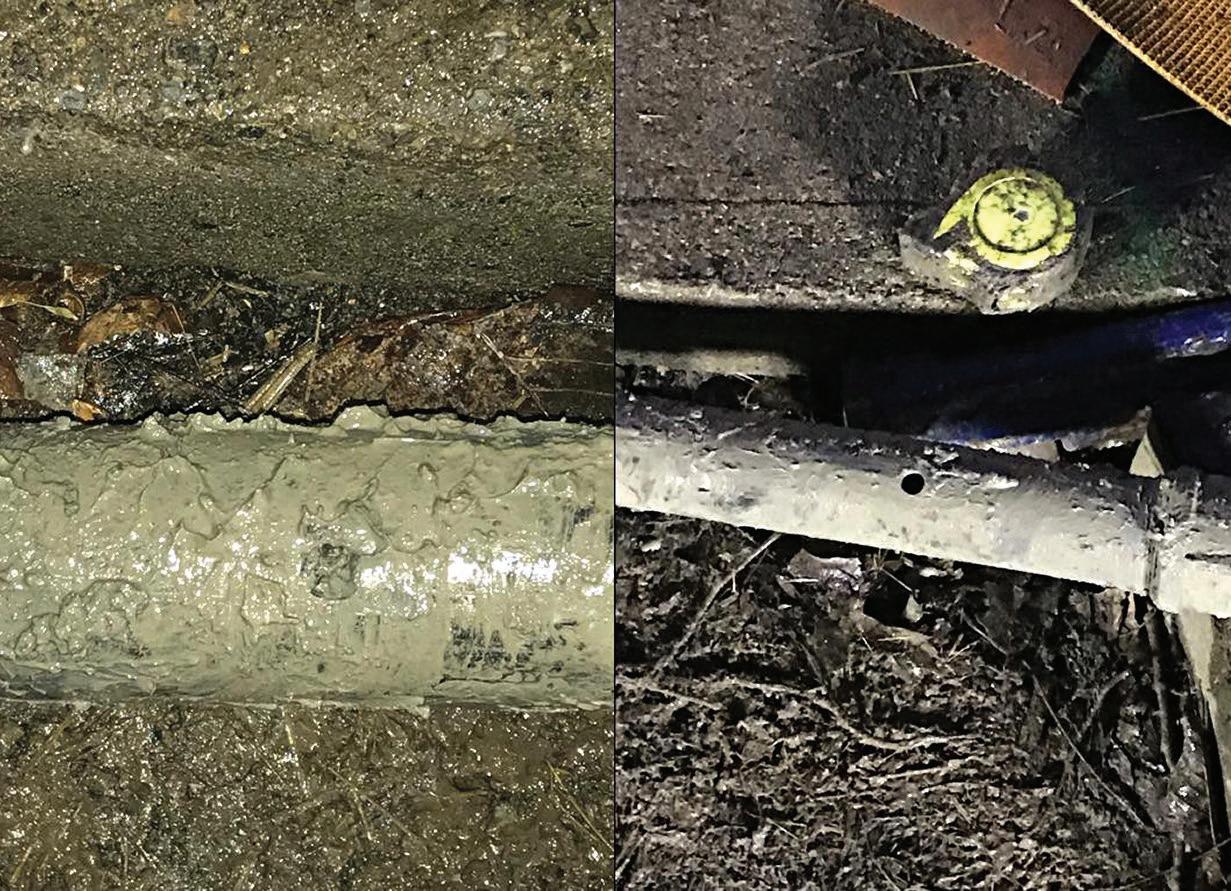
The grouting of the boreholes was completed over three days. The first day, the grouting operation was not able to proceed because the grouting shoe was clogged by aggregate. It became clear that the cement trucks had not been thoroughly washed from a previous load of cement (Figure 14).
The tremie pipelines were then removed to clean them from grout and to unclog the grout shoe and had to be re-installed into the borehole.
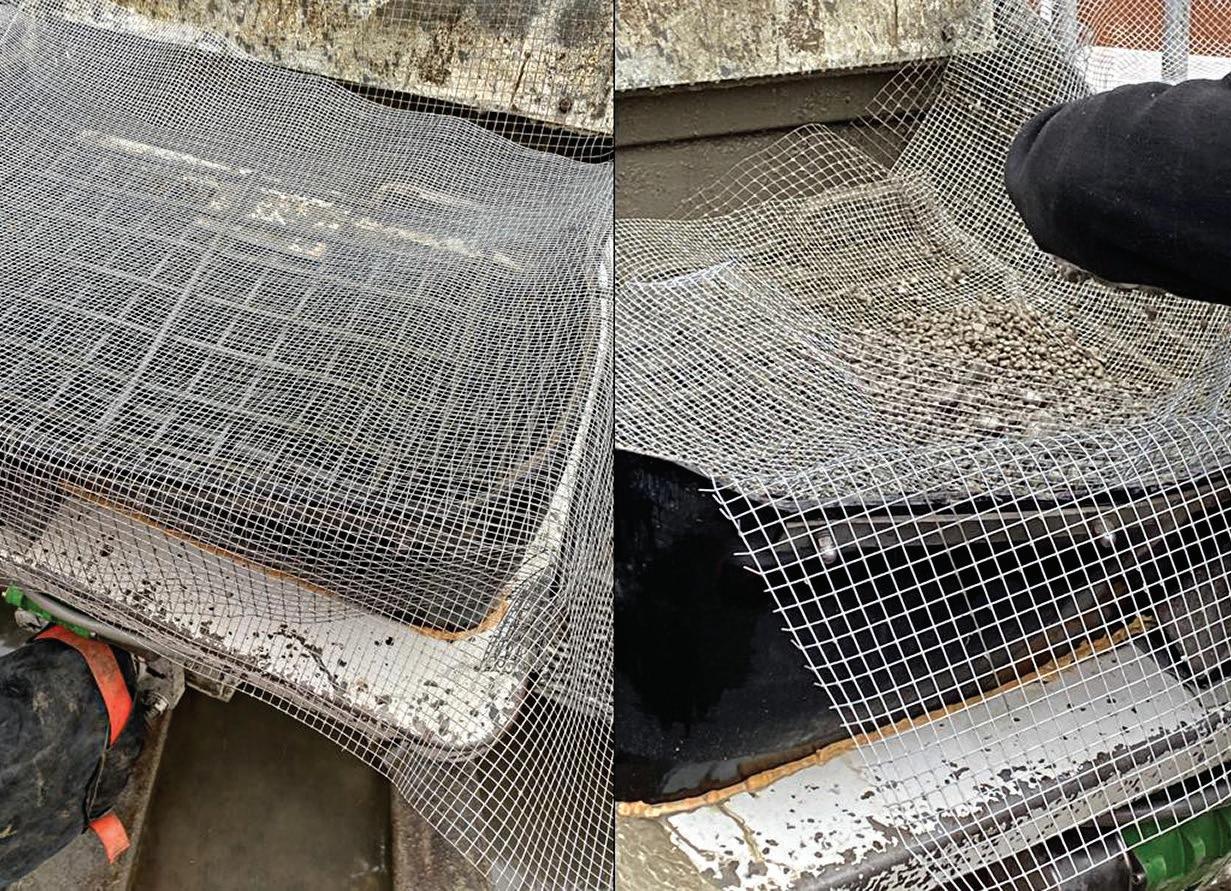
Truck washes were required prior to all loads of cement; however, it was evident that further protection against clogging was required. A screen was placed across the pump truck hopper to capture aggregate. During both instances, aggregate did accumulate in small amounts on the screens. In situations where truly neat cement is required and is not being batched on site, such screens are a simple and cheap measure to prevent a very costly delay.
Based upon the volume of grout pumped, pump pressure records, and estimates of the displaced bentonite volumes, the grouting operation created a plug which extended 50’ (15.2 m) past the ends of the tremie lines and up to the entry/exit pits.
The de-pressurization well was decommissioned two weeks after the groundwater cut-off/sealing operations were complete. Approximately four years later, no visible signs groundwater seepage around the grout seal up to the surface have been observed at the pump station (HDD entry) site. The site is subject to regular monitoring by the owner at this location as a matter of consistent operation. The current operations staff are aware of the potential for seepage at both the well location and the borehole location as an attempt to flag the presence of excessive/new wet ground or active seepage to the surface at these locations. No sign of change has been observed to date.
HDD technology can be applied successfully to slope drills and to sites with pressurized groundwater, but this is asking
more of the technology than a standard drill, and deserves additional levels of planning to identify and implement risk mitigation strategies. The following should be considered for use on such projects:
• Consideration if there is a strong driving factor to justify taking on the significant risk of applying HDD to slope or pressurized groundwater conditions.
• Conductor casing
• Packer/Blow-off-preventer
• Annular space sealing/groundwater cut-off
• Selective placement of the bore alignment within favorable soils
• Design treatment to account for restoration of the pre-existing groundwater regime


The Northwest Trenchless Journal sat down with Peter Lischewski, CEO of Raedlinger Primus Line since 2021, and John Moody, Director of Sales North America, who has over 25 years of experience in the construction industry and has spent the last nine years helping to establish Primus Line® in the Canadian and U.S. markets. They told us a bit about the business, and how Raedlinger has become the company it is today.
Q: Can you tell us a brief history of your company, and how it got started in the trenchless technology industry?
A: More than 30 years ago, Josef Rädlinger Sr. acquired a company that made weaving machines for fire hoses. Some years later, a division of his company looked for a solution for rehabilitating gas pipelines, sparking the idea for Primus Line®. Josef’s son Werner took on the development of a high-performance liner. After years of research and development, we were able to master Kevlar® fibres and the G-Liner was born. This product group has been successfully used since 2003.
Q: What types of activities and projects is your company currently involved in within Canada?
A: In Canada, we focus on rehabilitation projects for drinking water and sewer rising mains, collaborating with local partners to develop these projects. Our distribution partners ensure stocked materials for short lead times. The use of non-metallic solutions
for pipeline rehabilitation is growing. Alongside the water market, we are active in the oil and gas sector, especially for the safe transport of produced water in fracking operations using our Overland Piping system, which helps reduce CO2 emissions.
Q: Primus Line® is known for its versatility in transporting liquid and gaseous media. Can you explain how this system works and what makes it unique?
A: A Primus Liner consists of three layers, with a core made of Kevlar® or a Kevlar®-hybrid fabric. The inner and outer layers are tailored to the application, setting it apart from ‘through the weave’ products. Our flexible rehab pipe – a true FFRP – is independent of the host pipe, absorbing all operational loads, unaffected by thermal or seismic movements within a certain area. Its flexibility allows installation with bends up to 90°. In some cases, rehab sections over 2,500m can be installed in a single pull without intermediate connectors.
In Canada, we focus on rehabilitation projects for drinking water and sewer rising mains, collaborating with local partners to develop these projects.
Q: Could you describe the benefits of using the Primus Line® system for the trenchless rehabilitation of pressure pipes?
A: Overall, trenchless rehabilitation technologies have a positive impact on our society and resource consumption. Depending on the rehab section, CO2 reductions can be as high as 75 to 90% compared to open-trench installation. A positive side-effect of the short project execution time and the very small workspace required for installation is less environmental disturbance such as traffic congestion or noise. Other advantages, as already mentioned, are the bendability of Primus Line® and its long installation lengths.
Q: Primus Line® Rehab is a significant innovation in the industry. How does this technology improve the process of rehabilitating aging pipelines?
A: Our rehab material does not require any additional treatment such as UV or steam curing or sectional wedding at the construction site. There is no need for additional material testing after the installation. The short overall installation time, including significantly reduced logistics, results in less network downtime for clients. We do not want to overemphasise it, but the longer the installation length, the more significant Primus Line®’s USPs become: less ground-breaking activities and one of the few technologies to rehabilitate river or sea crossings at all.
These technologies offer significant sustainability benefits, particularly in reducing water loss in networks, where 20 to 60% of produced drinking water can be lost. Leakages in sewer rising mains are even more hazardous due to contamination. If resource consumption were prioritized in decision-making, the global impact would be signifi cant .
Q: What are some of the key steps involved in preparing and installing Primus Line® for pressure pipeline rehabilitation?
A: A proper engineering feasibility check, combined with a CCTV pipeline inspection to detect e.g., harmful obstructions, is essential for a successful rehab project. Our installation manual offers best practices for pipeline cleaning to maintain consistent Primus Line® quality worldwide. After cleaning with scrapers, grinders, or water jets, a second CCTV inspection confirms the pipeline’s readiness for rehabilitation. Only trained and certified partners handle Primus Line® installations. For challenging projects or new partners, one of our engineers will be on site to supervise the process.
Q: Your company also o ers Primus Line® Overland Piping. What are its main applications, and how does it benefit projects requiring temporary, above-ground piping?
A: After extensive evaluation, our Overland Piping system is now classified as an ANSI300 Temporary Surface Pipeline (TSP) and approved for ‘off lease’ use. The system is reusable and requires no additional treatments like welding. It comes with a spooler for easy unwinding and rewinding of pipe sections of up to 690m of 12" liner. Canadian customers have shown that a 6km Primus Line® TSP was installed in two days and dismantled in two, compared to several weeks for HDPE pipelines in the past. This system offers productivity, financial benefits and significant emission reductions.
Q: Quality is essential in your line of work. How does your company ensure the high quality of its products, from raw materials to final installation?
A: Strict safety standards along with factory standards set the quality benchmark for Primus Line®. Monitoring starts with
incoming goods, and sensors and cameras ensure wall thickness and consistency during production. Every pipe undergoes in-house pressure testing, with independent third-party testing further assuring clients of our certified high-quality products.
Q: Can you explain the importance of certifications for your products and the specific standards they meet?
A: Every manufacturer should have internal quality assurance procedures, with documented life cycle calculations based on this testing regime. We believe independent third-party testing is key for clients to evaluate different materials or solutions. We have conducted 10,000-hour tests showing a lifespan of at least 50 years for our material in standard water rehab projects. Primus Line® holds drinking water certificates in around 20 countries and is certified to NSF/ANSI 61 standards, particularly suitable for North America. Unfortunately, many tender processes focus on price per metre instead of taking into account quality and documentation standards, which can harm the reputation of the entire trenchless industry when projects are executed improperly.
Q: How do your installation partners and certified installers contribute to maintaining your high-quality standards and customer relationships?
A: Through our onboarding process, training and certification, we maintain close relationships with our installation partners. Collaborative project development strengthens these partnerships. Our sales team also works with end clients, sharing case studies to build confidence in our solutions. New client contacts are passed to regional partners for further development or tenders. Additionally, nationwide or international clients often request local partners for projects in different regions.
Q: Traceability is crucial for quality control. How does your company ensure every production batch of Primus Line® is traceable and meets all necessary standards?
A: Our production process includes several steps. Before starting production, a verification batch undergoes tensile and burst tests. After successful pretesting, production begins, with 360° monitoring automatically recording all relevant data. Each metre produced receives a unique code detailing the liner type, MOP, batch, date, machine and production length, allowing data retrieval even years later. The entire batch’s data is reviewed in a verification meeting with quality, production and process management before being released for sale. Purchased materials, such as connectors and tools, are quality-checked by logistics specialists before being sent to the construction site.
Q: What do you see as the future of trenchless technology, and how is your company preparing to meet the challenges and opportunities ahead?
A: Although trenchless technologies have been used for years, their full potential remains untapped. These technologies offer significant sustainability benefits, particularly in reducing water loss in networks, where 20 to 60% of produced drinking water can be lost. Leakages in sewer rising mains are even more hazardous due to contamination. If resource consumption were prioritized in decision-making, the global impact would be significant. Primus Line®’s small logistics footprint and lean production process emit less CO2 annually than a two-week cruise. As new applications emerge, these benefits will continue to grow.




LOW-PRESSURE SEWAGE (LPS) SYSTEMS AND THEIR GROWING ROLE IN VARIOUS ENVIRONMENTS CAN BE UNDERSTOOD AS A PRACTICAL SOLUTION TO THE CHALLENGES OF GRAVITY SEWER SYSTEM APPLICATIONS AND AS A RESPONSE TO CONTEMPORARY INITIATIVES CREATED TO PROTECT WATERSHEDS AND OTHER SENSITIVE ENVIRONMENTS.


BY SAM EICHENBERGER, P.ENG.
The phrase ‘sewage flows downhill’ is a succinct reminder of the practical challenges of wastewater management across communities. Low-pressure sewage (LPS) systems and their growing role in various environments can be understood as a practical solution to the challenges of gravity sewer system applications and as a response to contemporary initiatives created to protect watersheds and other sensitive environments. The strengths and weaknesses of LPS systems are examined in this article as are potential solutions to perceived limitations. The Utility Management team at KWL has recently explored several cases for LPS and provides some insights into potential applications.
Most municipal sewer systems rely on open-channel gravity flow to collect and convey wastewater to a collection or treatment facility. Since gravity sewers need sloping pipes to convey flow, the transport distance can be limited by topography before pumping is required. As more branches of the sewer system converge, the pipe diameter must increase, but often the slope becomes limited by the allowable depth of the pipe. Large, deep sewers are notoriously expensive and challenging to construct and maintain. Septic fields and tanks were historically used in areas in which gravity systems were not a feasible option. Septic fields rely on dispersal fields that use gravity to drain liquid
waste to the groundwater table and require periodic pumping activities for the removal of solid waste. Millions of septic fields were implemented during the urban sprawl following World War II, but by the late 1950s many were showing signs of eventual failure before the end of the expected service life. Failures resulted in negative human health and environmental outcomes from contaminated groundwater flowing into surface features like lakes and rivers.


then pumped through small diameter pipes installed directly below the frostline and following the natural landscape to a sewer




Alternatives were developed in the 1970s to address the adverse effects of septic fields and to provide affordable, dependable and safe wastewater management. LPS systems powered by private side pump stations were introduced to make ‘sewage flow uphill’ and became a widely used and successful solution. LPS systems are differentiated from the conventional gravity system by a piping network and the reduction of solid particle size in wastewater at each connection. LPS systems use a network of grinder pumps and submersible siphons designed to reduce waste stream particulates to a fine slurry using a grinding mechanism. Wastewater is then pumped through small diameter pipes installed directly below the frostline and following the natural landscape to a sewer main, lift station or treatment system. Pumps operate with high pressure and limited flow, a key adaptation developed in response to the limitations of the gravity system.
THE UPS AND DOWNS OF LOW-PRESSURE SEWER (LPS) SYSTEMS

LPS systems are a viable and efficient solution for areas facing unique challenges in sewage management. LPS systems are a popular replacement for failing septic fields in existing subdivisions, new developments with slow build out rates, areas with high levels of groundwater, waterfront properties and projects with difficult terrain that may include undulating, steep or extremely flat topographies. The technology offers a range of benefits and is a compelling choice across a variety of settings. Positive attributes of LPS systems can be summarised as follows:
1. Cost-effective installation and maintenance: LPS systems require smaller and shallower trenches than gravity systems, reducing overall construction expenses. The modular nature of LPS systems simplifies maintenance and allows for swift, targeted repairs that do not disrupt the entire network.
2. Adaptability to challenging terrain: Traditional gravity systems may be impractical or excessively expensive in regions with exigent terrain. LPS systems offer flexibility with routing


LPS SYSTEMS USE A NETWORK OF GRINDER PUMPS AND SUBMERSIBLE SIPHONS DESIGNED TO REDUCE WASTE STREAM PARTICULATES TO A FINE SLURRY USING A GRINDING MECHANISM. WASTEWATER IS THEN PUMPED THROUGH SMALL DIAMETER PIPES INSTALLED DIRECTLY BELOW THE FROSTLINE AND FOLLOWING THE NATURAL LANDSCAPE TO A SEWER MAIN, LIFT STATION OR TREATMENT SYSTEM.
and navigation, making them the ideal solution in areas of varying elevation as well as densely populated urban environments. Installations typically involve flexible piping placed directly below the frost line, allowing for creative routing that follows a natural pathway or avoids specific landscaping features.
3. Remote and sparsely populated areas: LPS systems are particularly effective in remote and sparsely populated areas in which a centralized gravity system may not be feasible. The ease of installation and the reduced need for extensive excavation promote LPS systems as the pragmatic solution when avoiding logistical challenges associated with traditional methods.
4. Elimination of inflow and infiltration: Pressure pipes eliminate sources of inflow and infiltration, and are leak tested to the standards of potable water supplies. Inflow and infiltration are possible at the
gravity sewer connection and sump on private property, an element eliminated through the installation of the pump station inside a home in a basement mechanical room.
LPS systems offer multiple advantages that may be mitigated by negative situational realities, described below:
1. Energy consumption: The use of pumps in LPS systems contributes to the operational costs of homeowners through energy consumption. Energy-efficient pump technologies and the use of renewable energy sources can offset perceived economic and environmental drawbacks.
2. System vulnerability: LPS systems may be susceptible to power outages or pump failures, disrupting the flow of wastewater. Adequate backup systems and regular maintenance are essential elements in risk management.
3. Maintenance: Private pump stations require regular maintenance and will rely


‘SEWAGE DOESN’T FLOW UPHILL,’ BUT WITH THE RECOMMENDED TECHNOLOGY AND FORWARD-THINKING STRATEGIES, IT CAN PROGRESS WITH EFFICIENCY AND WITH SUSTAINABILITY AS A CRUCIAL ELEMENT. LPS
SYSTEMS OFFER PRACTICAL SOLUTIONS TO PRESENT CHALLENGES POSED BY TRADITIONAL GRAVITY SYSTEMS AND AREAS WITH UNIQUE TOPOGRAPHICAL, ENVIRONMENTAL AND LOGISTICAL CONSIDERATIONS.
on increased efforts from homeowners who are accustomed to the gravity system and its relative ease of operation as a sanitary service. Pumps will need to be replaced upon expiration.
4. Pump sump location: The pump sump must be located within the private homeowners’ property, typically installed at a low point or near a low side of the structure to enable sewage flow through gravity to the station to be pumped off site. Stations generally have a diameter no larger than 1.5 metres but contain appurtenances that must be accessible at grade. As previously mentioned, the installation of the pump station within the house in a basement utility room can offset predicted complications.
Utilities have at times balked at the idea of LPS systems due to perceived risks of maintenance challenges, however our practical experience suggests otherwise.
LPS AS A SOLUTION FOR TOMORROW’S CHALLENGES
Our team has recently reviewed several interesting applications for LPS, particularly
as a solution for replacing aging gravity infrastructure or on-site disposal systems.
• Some sewers were installed in environmentally sensitive or natural hazard areas prior to modern regulations that now make in-situ replacement or rehabilitation unfeasible. These sewers can be difficult or impossible to properly maintain due to risk to worker health and safety, which increases risks for utilities.
• On-site sewerage disposal (i.e., septic systems), especially in rural recreational areas that experience high seasonal loads can have a negative impact on water resources. These areas would be impractical to service with traditional gravity systems.
• Areas subject to periodic flooding or sewer backups due to wet weather flow can benefit from LPS because the check valves inherent in LPS prevent backflow, while the pumps can still discharge against modest backpressure.
Ongoing regulatory changes create ripple effects throughout the water sector and inform community approaches to planning
sewerage infrastructure. Alternative solutions like LPS systems can be affordable strategies to meet requirements. Additionally, collaborative efforts between local authorities, environmental agencies and engineering experts will bolster efforts for environmental and community sustainability.
‘Sewage doesn’t flow uphill,’ but with the recommended technology and forwardthinking strategies, it can progress with efficiency and with sustainability as a crucial element. LPS systems offer practical solutions to present challenges posed by traditional gravity systems and areas with unique topographical, environmental and logistical considerations. As communities navigate the ripple effect of regulatory changes, the integration of innovative sewage management solutions becomes a crucial aspect of the health of waterways and the sustainability of urban environments.
SOURCES:
eone.com/images/files/secret_life_pressure_sewers.pdf www.pumpsandsystems.com/grinder-pumpsevolution-pressure-sewer-systems

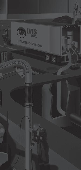


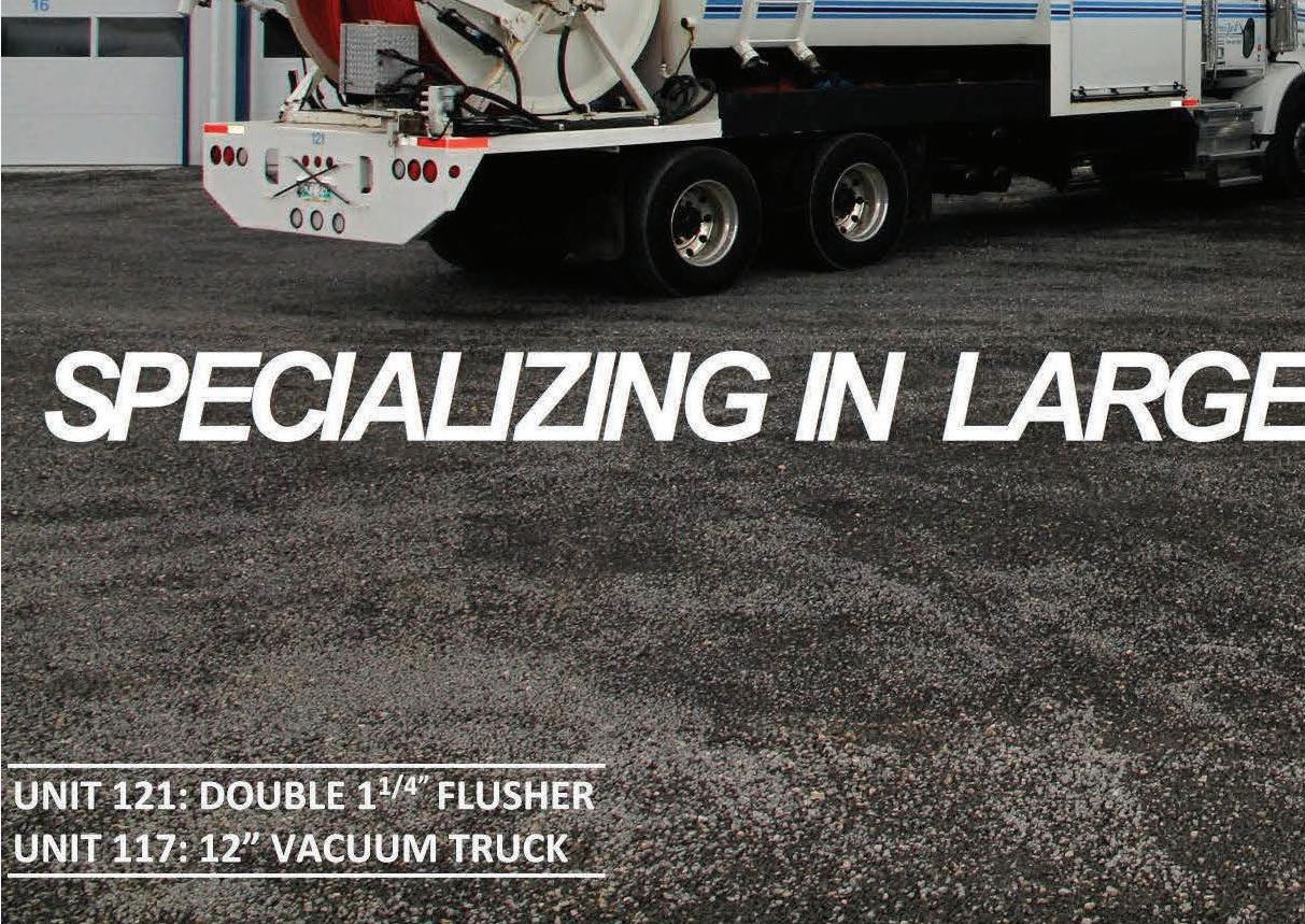
• Maintenance Programs


• Secondary Utility Locates/GPR
• High pressure flushing/vacuum
• CCTV (camera) inspections of sewer lines
• Lift Stations-maintenance & refurbishing
• Hydro excavating utilities, piles, trenching
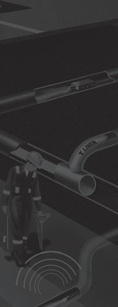


• High Rail Unit for hydrovac, flushing, vacuum
• Pipe bursting/open cut sewer replacement
• Relining of sewer lines, storm lines, laterals, T-liners, manholes and lift stations and potable water lines




Sam Eichenberger is a civil engineer who specializes in condition assessment and rehabilitation of linear infrastructure, specifically focusing on trenchless rehabilitation technologies. His work spans planning, condition assessment, design, contract administration, project management and construction field review.
He is the current Chair of the North American Society for Trenchless Technology’s British Columbia Chapter and is always happy to teach others about the benefits of these low-carbon emission options for construction projects.
This article was originally published in the Summer 2024 BC Water & Waste Association magazine, Watermark Thank you to the association and to Sam Eichenberger for reprint permission.
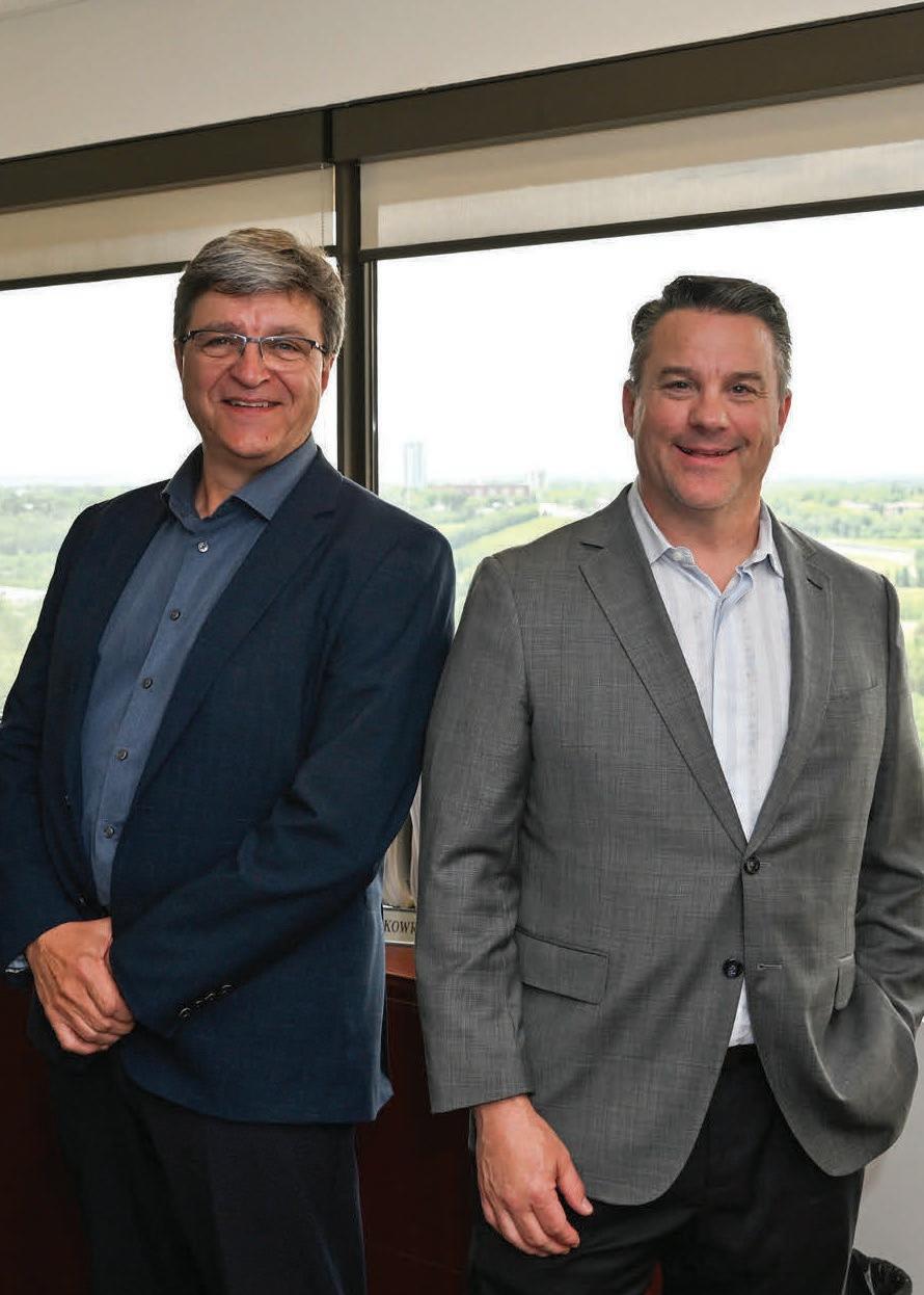
Associated Engineering is pleased to announce the appointment of Jeff Fetter as our new Senior Vice President, Civil Infrastructure. With a proven track record in delivering complex infrastructure and water projects, Jeff brings a wealth of experience to our staff and clients to design sustainable and resilient infrastructure.
After 35 years of dedicated service with Associated Engineering, Chris Skowronski is transitioning into retirement. Chris has been instrumental in fostering a culture of excellence and innovation. We thank him for his leadership and passion.
Congratulations to both Jeff and Chris!





Abstract
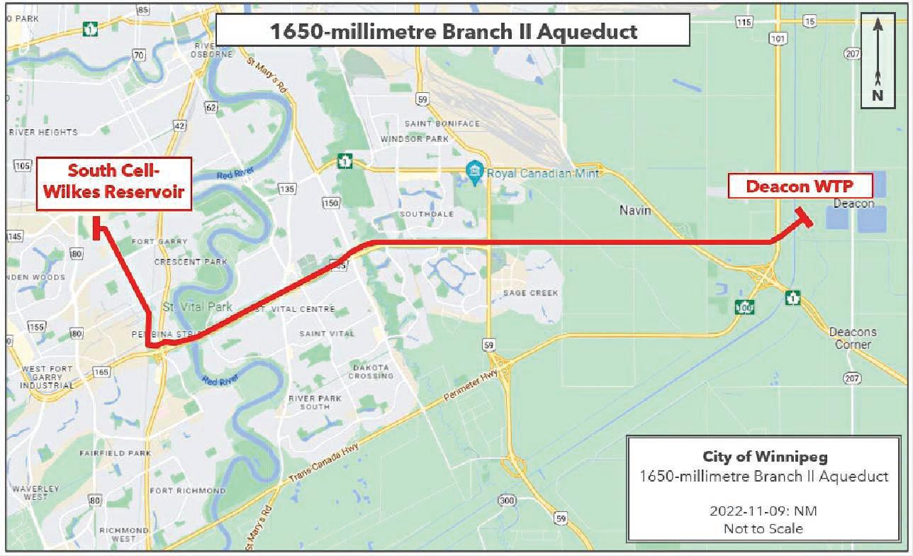
the South Cell of the Wilkes Reservoir.
SHANE COOPER, C.E.T., AECOM, Municipal Technical LeadCustomer Success Manager – PipeInsights (Canada)


The City of Winnipeg retained Pure Technologies, a Xylem brand (Pure Technologies), via a successful tender to conduct a condition assessment of the prestressed concrete cylinder pipe (PCCP) in the 1,650-millimetre Branch II Aqueduct in Winnipeg, Manitoba.
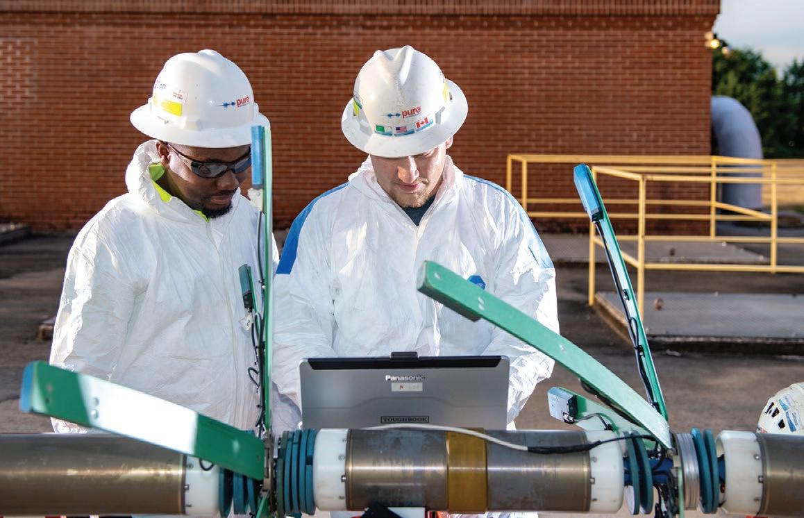
On September 21, 2022, Pure Technologies used its free-swimming proprietary PipeDiver™ platform, a non- destructive electromagnetic inspection technology to locate and identify pipes that have broken prestressing wire wraps. PipeDiver was determined to be the only feasible technology as the line could not be taken out of service.
The PipeDiver inspection covered a cumulative distance of 18.63 kilometres and spanned a total of 3,826 pipes from the Deacon Water Treatment Plant to
Analysis of the data obtained during the inspection determined that 33 pipes in the 1,650-millimetre Branch II Aqueduct displayed an electromagnetic anomaly consistent with prestressing wire damage, ranging from fi ve to 20 broken wire wraps.
Following the conclusion of the inspection, Pure Technologies performed structural evaluations on the PCCP pipes of the Branch II Aqueduct. The structural evaluations are intended to determine if the pipeline is operating under safe conditions based on design standards, as well as show the structural consequences of broken prestressing wires on a pipe. These evaluations include:
• American Water Works Association C301 and C304 Design Analysis
• Three-dimensional non-linear finite element analysis (FEA)
The Branch II Aqueduct was constructed in 1958 to 1959, to service the expanded regional water system during the City’s second large growth period, in the 1950s and 60s. The 1676 mm Prestressed Concrete Cylinder Pipe (PCCP) pipeline was designed to convey potable water from Deacon Reservoir to the newly constructed Wilkes Reservoir and W.D. Hurst Pumping Station. Since its original construction, major system upgrades have increased the system capacity: Deacon Booster Pumping Station (DBPS) in 1979 and the Winnipeg Water Treatment Plant (WTP) in 2009. The Branch II Aqueduct conveys approximately 60% of the City’s drinking water daily, and is, by every metric, a critical component of the City’s regional potable water system.
There are many contributing factors that enable the safe, reliable operation of the

Branch II Aqueduct. Condition assessment of the pipe is one critical program used to capture the current state of the pipe condition and ascertain whether active deterioration processes are present and were active in the past. All assets require some form of assessment and mitigation over time to maximize their useful life or service level expectation.
The RFP for this project specifically requested the development of a program to conduct an electromagnetic survey of the Branch II Aqueduct using a free-swimming tool to carry out a prestressing wire break survey under live flow conditions. While a wire break survey is a critical aspect of condition assessment for PCCP pipe, it is but one measure of deterioration and does not capture all failure limit states for PCCP, nor a number of other common deterioration modes that may lead to failure. Free swimming electromagnetic (EM) tools often provide a convenient method to carry out wire break surveys with limited impact on operations, however, they carry inherent risks themselves as an inspection method that requires to be assessed prior to deployment. They are also limited as a condition assessment technique to the observations that can be made in a wire break survey and their accuracy in wire break detection can be limited by the operating mode that needs to be employed to facilitate safe tool deployment.
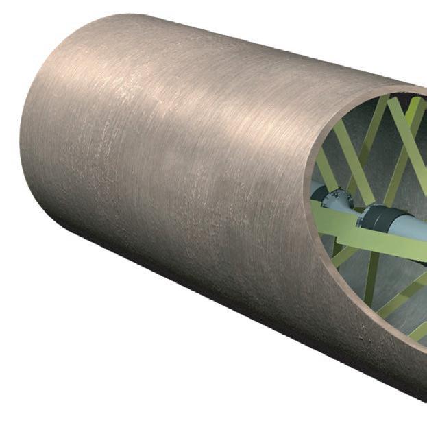
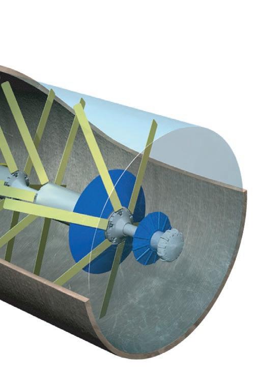
The PCCP installed for the Branch II Aqueduct is Embedded Core Pipe (ECP), where the pipe consists of a concrete core with an embedded steel cylinder. The resulting core is then wrapped with pretensioned prestressing wires placing the core/ lining into compression.
PCCP failure modes for both types of pipes are typically driven by material degradation. In the pipe barrel external deterioration of the outer mortar coating ultimately results in corrosion of the prestressing wires and can lead to a catastrophic failure mode. The concrete/mortar coating on the pipe exterior encases the pre-stressing wires, elevating the pH to the 12 or 13 level, which prevents the initiation of corrosion and resultant breakage of the prestressing wires. Where the outer coatings are exposed to undesirable soil chemistry and electrochemistry (e.g., elevated sulphates, chlorides, etc.) the coatings are more


susceptible to either break down (with sulphates) or lose their corrosion protective ability (with chlorides) which subject the wires to accelerated corrosion rates due to their high stress levels. Higher absorption values of the exterior mortar as a result of inadequate quality control during the manufacturing process can also expose the coatings to premature break down in less extreme exposure conditions. Failures of this type are not usually influenced by pipe diameter, but by a loss of tensile capacity as larger broken wire zones will allow the core to come out of compression.
Joints are also potentially susceptible to corrosion and ultimate failure. The risk is dependent on the quality of workmanship and materials related to installing the internal and external joint grout. The gateway for joint corrosion is either poor quality or poorly applied concrete mortar at the joints. Poor installation practices may also create an environment which places additional stresses on the pipe wall in longitudinal bending which results in circumferential cracking and consequently exposure of the steel components (cylinder or wire) to a corrosive environment.1


to Inspect the Branch II Aqueduct
The technology utilized to carry out prestressing wire break surveys is known as remote field transformer couple (RFTC) inspection. Due to the daily volume of water supplied to the City of Winnipeg through the Branch II Aqueduct, it was determined that the inspection must be completed with the pipe ‘in service,’ meaning no shutdown of the pipe could take place to facilitate inspection. In terms of carrying out inspections with the Branch II Aqueduct in- service, there is only one company in North America, Xylem, who utilize their PipeDiver platform to conduct RFTC inspections in an in-service mode as long as operating conditions can be developed to facilitate tool deployment and data collection in a real time operating mode.
The scope of this project included a condition assessment of the Branch II Aqueduct using the listed investigative techniques:
• Inline pipe wall assessment using the PipeDiver electromagnetic tool to quantify and locate wire breaks in the PCCP watermains within ±0.3 m. This inspection also provided an internal visual inspection via the PipeDiver cameras, to identify signs of significant deterioration, particularly at the pipe joints.
• American Water Works Association (AWWA) C301 and C304 Structural Design Check
• Three-dimensional, nonlinear finite element analysis (FEA)
• Recommendations for future serviceability of the pipeline.
Electromagnetic Inspection (EM) is a nondestructive technique that detects broken wires and broad areas of cylinder defects. The PipeDiver inspection tool can be inserted and retrieved in a fully operational pipeline. The inspection tool is neutrally buoyant and is carried by the flow of water, travelling at approximately 90% of the flow rate. Therefore, after insertion it travels with the flow until it reaches the desired capture and extraction location. The location of the PipeDiver is tracked from above ground using electric above ground markers.
For the insertion the PipeDiver technology used an existing 400 mm opening. During the Inspection Phase, the inspection tool traverses through the pipeline and induces a magnetic field on the metallic components of the pipe (wire and cylinder). Receiving sensors placed near the pipe wall record a resulting magnetic signature that is influenced by the presence of broken wires or wall loss. The signature is recorded on the inspection tool and data from the inspection is subjected to a detailed data analysis process that identifies and quantifies damage on the pipe. Extraction was via a ROV at the Wilkes Reservoir.
Challenges
The Branch II Aqueduct supplies the City of Winnipeg water distribution system post- treatment after the water treatment plant. The alignment of the system traverses both rural agricultural and urban environments.
Weather played a role in planning, as freezing winter environments in Winnipeg are notoriously difficult to work in, especially when dealing with water systems. Further complicating the schedule was a spring flood in the Red River Valley, which elevated the normal summer water levels in the Red and Assiniboine Rivers. Th is impact lasted well into the summer and delayed the planned inspection, as partial draining of the Wilkes Reservoir would be required to accommodate the extra water flow during inspection. The reservoir could not be drained, as the stormwater system that would take the drained water was at capacity and not draining due to the elevated river levels. Th is pushed the inspection date into the fall, when seasonal water demand would be lower in Winnipeg should the aqueduct need to be taken offl ine for any unforeseen reason during inspection.
The PipeDiver inspection tool also needed to traverse three siphon sections of the aqueduct, one of which was located under the Red River. The confi guration of the vertical bends of the siphon needed to be factored into the inspection process, as the fi rst and last set of bends featured capped pipe stubs that could potentially cause the PipeDiver to get stuck while attempting to negotiate the bends. Pure successfully mitigated the associated risk issue by ‘tilting’ the lead section of the PipeDiver down to induce a more vertical movement when going through the bends.
Electromagnetic data was collected on September 21, 2022, for the 1,650-millimetre Branch II Aqueduct. The inspected section spanned an overall distance of 18.63 kilometres, collected over a period of approximately 13 hours. From set-up to completion the inspection took over 18 hours and Pure deployed two crews to facilitate. A summary of the total number of pipes that had electromagnetic signatures consistent with broken prestressing wire wraps, as well as pipes with other electromagnetic anomalies, is presented below.
Of the 3,826 pipes inspected in the 1,650-millimetre Branch II Aqueduct, 33 pipes had electromagnetic anomalies consistent with broken prestressing wire wraps. The distressed pipes are presented in Table 2 and are sorted in descending order by the total number of broken wire wraps.


While the PipeDiver inspection techniques provide quantitative data regarding areas of pipe deterioration, this information alone does not provide the significance of the condition of a pipe. For example, wire breaks may be present, but this may not require the immediate rehabilitation or replacement of the pipe section allowing Winnipeg to manage and/or monitor the deterioration, focusing critical resources on higher risk areas of the infrastructure. The significance of the condition of a pipe should be ascertained through an engineering analysis to determine the severity of the deteriorated areas relative to the actual loads that act on the pipeline. Pure Technologies has developed a series of structural and statistical models based on current AWWA standards, that allow for immediate repair recommendations as well as long-term planning for future inspections and/or renewal strategies. These advanced structural models provide insight as to the true condition of the pipe rather than just reported anomalies.
Table 3 lists the pipe class design specifications used by Pure Technologies for the structural analyses. All values not obtained from the specifications provided
by the City of Winnipeg are the minimum requirement values provided in AWWA C3014 and AWWA C3045
FEA is a method for modeling complex geometry under diff erent loading conditions. Recent developments in fi nite element modeling and increased computational speed allow for the analysis of complex nonlinear problems, which are required to provide accurate models of PCCP with broken prestressed wire wraps. The FEA model has been developed by Pure Technologies to determine the structural consequence of broken prestressed wire wraps. Th is method incorporates the pipe design specifications, design parameters, and the current condition of the prestressed wire wraps, as determined during the electromagnetic inspection. During the analysis, the model of a pipe design is subjected to internal pressure, pipe and fluid weights, and external loads while varying the number of broken wire wraps. Pure Technologies uses a commercial fi nite element software, Abaqus®, to investigate the response of a PCCP under these diff erent loading conditions.
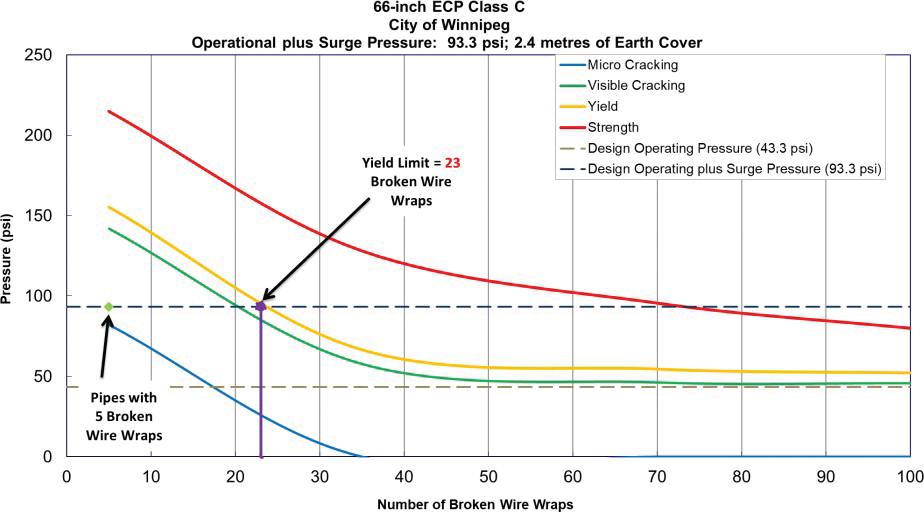
The FEA model predicts the performance of a PCCP using the tensile strengths of prestressing wire, steel cylinder, and concrete core, as well as a plasticity algorithm that simulates concrete crushing in compression regions. A performance curve, displaying the effects of broken wire wraps, is formulated. and used to determine the number of broken wire wraps required for the design to exceed theoretical FEA Limits. The values used in the models were taken directly from the provided specifications and the contemporary AWWA C301 design standards.
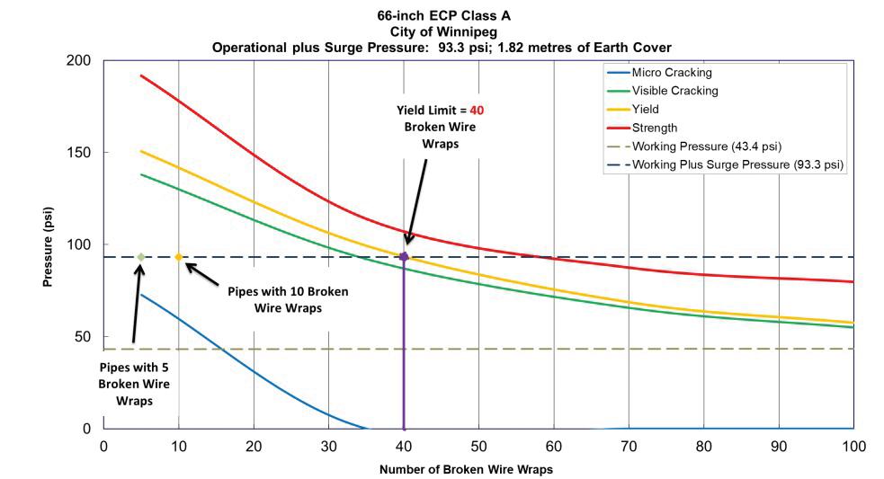
The number of broken prestressing wire wraps that a pipe design will tolerate under operational and surge conditions can be determined using a FEA -based pipe performance curve. Pure Technologies uses four FEA Limits to evaluate the condition of a pipe with wire wraps damage:
• Micro Cracking,
• Visible Cracking,
• Yield
• Strength Limits.
Table 4 defi nes the limits used by Pure Technologies to describe the predicted condition of a PCCP with a known quantity of broken wire wraps. The actual


number of broken wire wraps required to reach these Limits varies per the pipe design and earth cover.
The values used to represent the performance of the steel components are based on the yield and ultimate strengths provided on the pipe design specifications sheet by the City of Winnipeg. The yield strength for the prestressing wire is typically 85 percent of its ultimate strength, while the yield strength of the steel cylinder is either denoted on the pipe design specification sheet or Condition Assessment Report 1,650-millimetre Branch II Aqueduct City of Winnipeg taken from the design standard in place at the time of production. The Yield Limit is reached when either the steel cylinder or the prestressing wire exceeds its yield strength.
The ultimate strength of the prestressing wire is dictated by the gauge and class of the wire, while the ultimate strength of the steel cylinder is determined by the grade of the steel. The Strength Limit is exceeded when one of the PCCP components reaches its ultimate strength, which, theoretically, will result in failure of the pipe.
By evaluating the predicted structural condition of a pipe using FEA and analyzing all critical variables, a risk assessment for all distressed pipe segments can be performed to determine the condition at which a pipe with broken wire wraps should be rehabilitated. The FEA evaluates the impact of a growing number of broken prestressing wire wraps on the performance of a pipe and the corresponding likelihood of failure associated with this damage.
The limit that a pipe exceeds on the FEA performance curve is only one factor to consider when deciding whether to rehabilitate a pipe with broken prestressing wire wrap damage. Other critical variables, such as redundancy and consequence of failure should also be considered when determining the risk tolerance associated with a distressed pipe. Once a pipe reaches the Yield Limit, the rate at which broken wire wraps occur may increase until the Strength Limit is reached.
Pure Technologies typically recommends a pipe should be rehabilitated when the number of broken wire wraps meets or exceeds the Yield Limit on the FEA performance curve. Note that reaching the Yield or Strength Limit does not necessarily indicate immediate failure of the pipe, as the methodology of how the distressed pipe segments are evaluated is a conservative assessment of the pipe condition.



Based on the fi ndings of PipeDiver electromagnetic inspection and the associated structural analysis, the following conclusions and pipeline management recommendations are presented for consideration by the City of Winnipeg:
• Electromagnetic inspection of the Branch II Aqueduct determined there are 33 pipes with broken prestressing wires, representing 0.86 percent of the overall pipeline. The number of broken prestressing wire wraps ranges from five to 20.
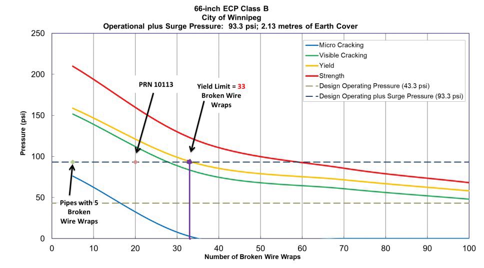
• A finite element analyses (FEA) calculated a Yield Limit of 40 and 33 broken prestressing wire wraps for the Class A and Class B pipes respectively, based on a working plus surge condition of 93.3 psi. At this evaluation pressure, all Class A and B pipes with broken wire wraps have exceeded their Micro Cracking Limit. Zero (0) Class A or B pipes with electromagnetic anomalies consistent with broken prestressing wires exceeded these Yield Limits.
• As pipe specifications were not available for Class E pipes, it is conservatively assumed that they have the same Limits as the Class B pipes. At this evaluation pressure, all Class E pipes with broken prestressing wire wraps have exceeded their Micro Cracking Limit. Zero (0) Class E pipes exceed the Yield Limit of 33 broken wire wraps.
• American Water Works Association (AWWA) C301 and C304 design standard evaluations were performed, the standards in place at the time of manufacture (1959) and today, and the Class A and B pipes in the Branch II Aqueduct continue to meet required design criteria for safe operation.
Where larger clusters of pipe breaks were found during the inspection, external inspection of those pipes is being considered to confirm the condition of the concrete pipe. Visual confirmation and/or concrete sounding for delamination are amongst the options to attempt to confirm the pipe-break results. In the pipe segment that exhibits 20 wire wrap breaks (10113), it has been determined that the 20 breaks are actually two sections of ten wire breaks each, and are far apart enough from each other in the pipe segment that they may be classified as two separate occurrences of wire breaks, and that the pipe is not in any critical yield condition state. Excavation may be able to assist in confirming this condition.
Conduct a pressure analysis of the Branch II Aqueduct by installing transient pressure monitors along the pipeline, particularly at the pump station, to obtain a current pressure profile of the watermain, and determine if any potentially detrimental pressure surges are occurring. Structural analysis conducted for this report is based
on design pressure data from 1959 as no present-day pressure data was provided at the time of inspection. Actual operating pressure information would refi ne the fi nite element analysis Limits and allow for more accurate management recommendations of distressed pipes and operating conditions of the Branch II Aqueduct.
Depending on the results of the pressure monitoring, reinspect this portion of the watermain electromagnetically in three to five years, or sooner if operating conditions change significantly, to continue to track the condition of the 33 pipes with prestressing wire damage and proactively manage the future serviceability of the watermain. The City can also consider the use of real-time wire break monitoring technology via acoustic surface mounted sensors.
Prior to the next electromagnetic reinspection, conduct an acoustic leak and gas pocket inspection. The PipeDiver inspection platform does not detect leaks, which can be located at the pipe joints or in the barrel of the pipe. Gas pockets can reduce the hydraulic capacity of the watermain and amplify the effects of any pressure surges, should they occur.
The City of Winnipeg should remain focused on operating the Branch II Aqueduct following industry best practices, specifically on maintaining a stable, consistent pumping process and operating pressure, stable above ground conditions and external loading on the pipe, and routine maintenance of features such as air valves and in-line valves.
1. Romer et al, AWWA Research Foundation, Failure of Prestressed Concrete Cylinder Pipe, AWWARF, 2008.
2. Pipe Classes are determined by depth of cover (A= 1.82m; B = 2.13m; C = 2.4m; E assumed same limits as class B)
3. The Break Position of the region with broken wire wraps is measured from the low station of the distressed pipe to the center of the distress region and was rounded to the nearest 0.1 metres.
4. American Water Works Association (AWWA), 1984. AWWA C301 Standard for Prestressed Concrete Pressure Pipe, Steel-Cylinder Type, For Water and Other Liquids, Denver, Colorado.
5. American Water Works Association (AWWA), 2014. AWWA C304 Standard for Design of Prestressed Concrete Cylinder Pipe, Denver, Colorado











With

Brandt


We are up for any challenge. Complex projects are opportunities to demonstrate our unmatched skill, outside-the-box innovations, and unyielding strength. Whether you are looking for a trenchless solution to minimize surface disruptions or need a consultation on the best tunnelling method approach to add value to your designs, we will exceed your expectations for quality, safety and sustainability.
Partner with Michels Canada and expect more.

