
Studio Applied Architecture
division (Byggnadsmaterial/Building Materials) and the University of Applied Science in Saarbrücken HTW. The students worked in groups of about 5-6 con sisting of KTH students (from both the architectural and the engineering departments) and architecture students from HTW.Inweek 8 of the project, the five different groups presented their projects after which one project was eventually chosen to be built by a jury, consisting of teachers and people from the industry. This booklet is to document all the five bridges that were designed for the competition.
This booklet was written in conclusion of the studio fourth project of the studio Applied Architecture at KTH Arkitekturskolan. The task of this project was to design and build a pedestrian timber bridge (span 10 m), con sisting of prefabricated sections manufactured in KTH’s “Snickarhallen”, over the creek Igelbäcken in Järvafältet, Stockholm. The work process was divided in four phases of which the second and third were organised as an architecture/engineering competition resulting in a win ning scheme that will be built. Project 4 was laid out as a collaboration bet ween the KTH Architecture School, the KTH engineering
Project 1 Garden Bridge Project 2 21.8° Project 3 84 Hands Project 4 Long Bench Bridge Project 5 Bridge of Truss.T 726046244 Projects
Engineering
Project 1 Architecture KTH Lidia RenéTorulfProykinaJörnholmHitimana Architecture HTW Niclas ChristianHertelBegon
KTH Frank Chia Muze Lu
Garden Bridge
Concept
For our bridge concept we came up with 3 clear design principles to help us guide our process:
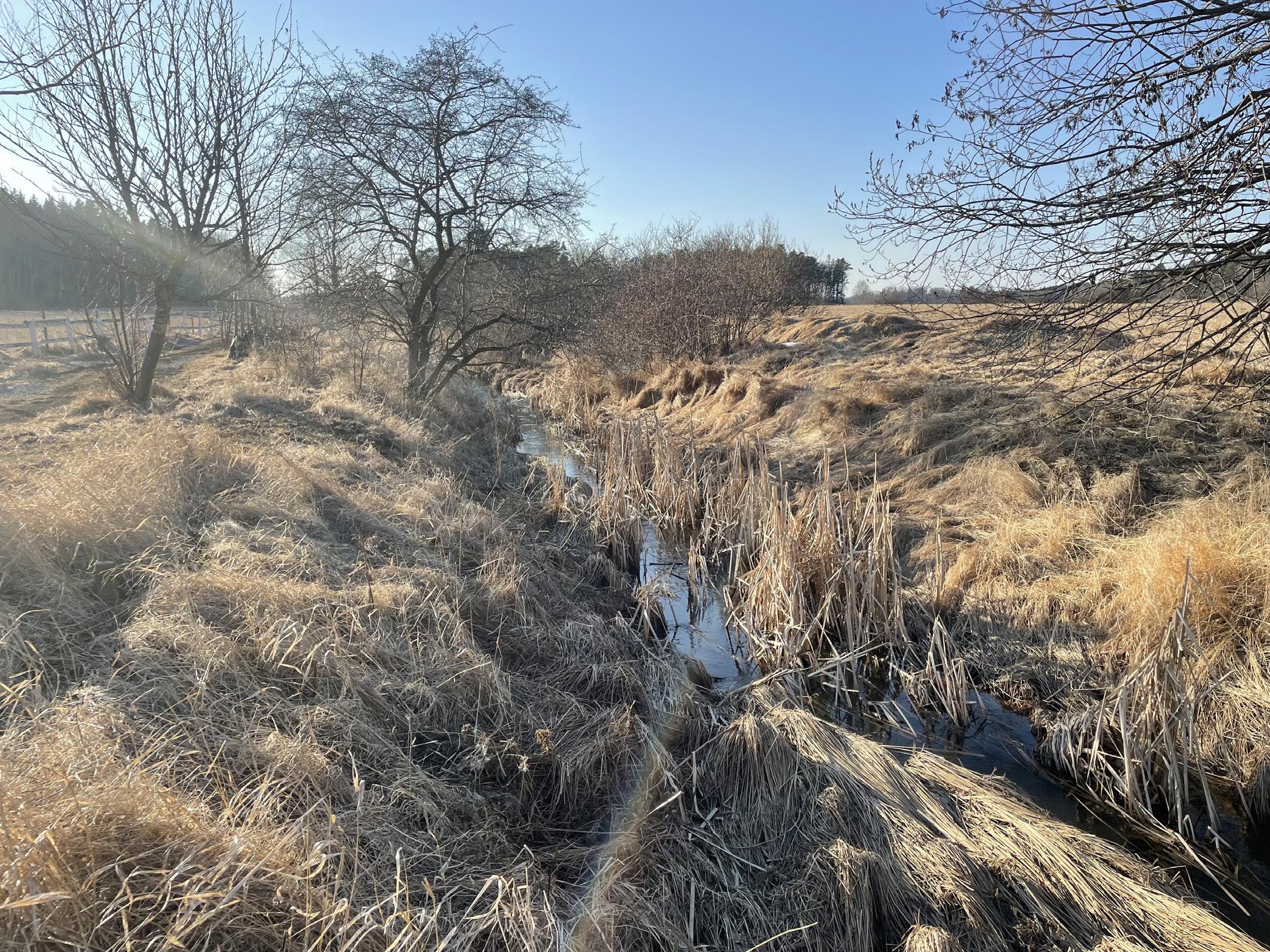
Location
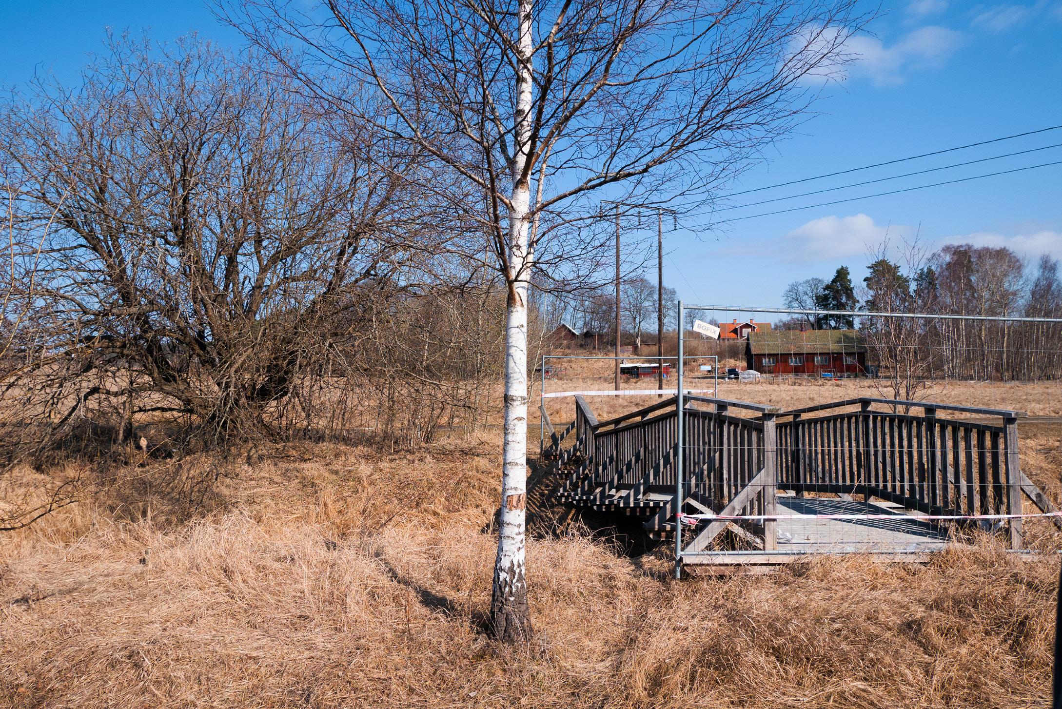
The site is located in Rinkeby, in a park/field area called Järvafältet. Close to the site there are multiple other foot bridges and a car bridge. Therefore, our approach to the project was to provide the users with something the other bridges couldn’t by creating an experience for them.
Garden Bridge 5 82
1. To create an interesting and tasteful design that would attract pedestrians - our inspiration came from 1800 English 2.Gardens.Todesign a raised bridge that will provide a nice vantage point for the user to enjoy the landscape
3. To design a bridge that will last more than 40 years by protecting the structure and designing an easily replaceable railing.
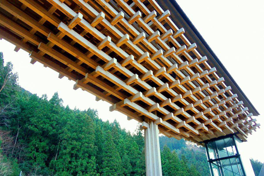
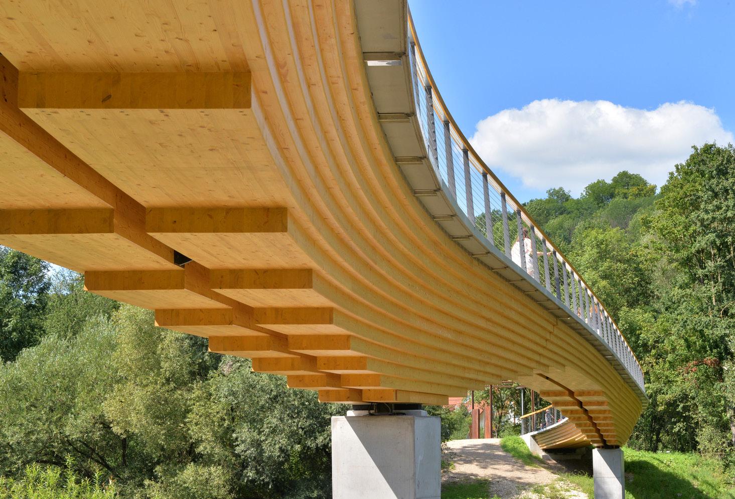
1) Yusuhara Wooden Bridge Museum, Kengo Kuma
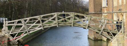
3) Mathematical Bridge, Cambridge
2) Curve Girder Bridge Neckartenzlingen, Ingenieurburo Miebach
Inspiration & Idea Sharing
Garden Bridge 6 82
In the beginning of the project we came together as a group and brainstormed ideas by sharing bridge designs we liked and found interesting. We narrowed them down to a few that we liked and that would fit into the 3 main princi ples we agreed upon in the beginning of the process. Then we further reduced the number of inspiration projects by what would be buildable with the materials we had and tried a few different variations.
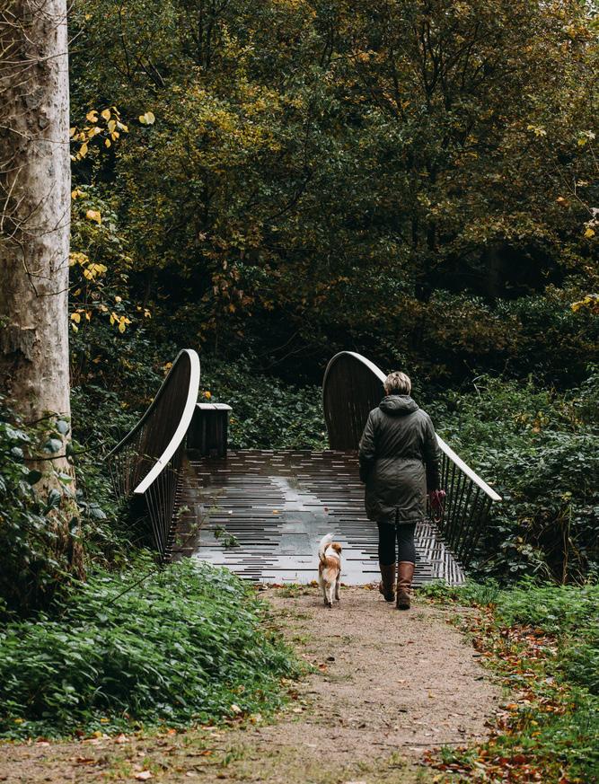
5) Windesheim Bridge, NEXT Architects
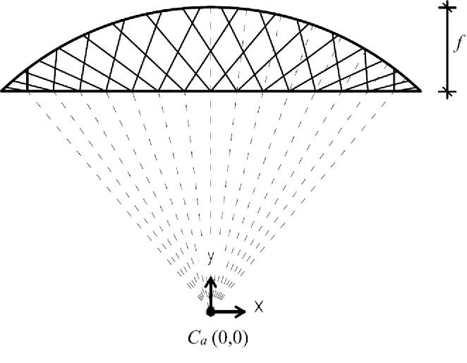
4) Parametric Study of Radial Hanger Pattern for Network Arch
Initial Design Variations
Garden Bridge 7 82
Version 2 Longitudinal Stacking Method Axo Render
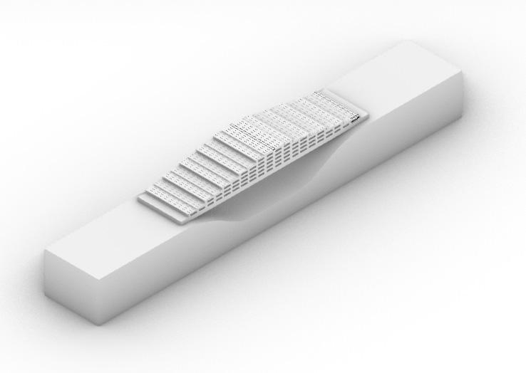
We explored different methods of creating an elevated bridge, one by stacking elements transversely and one by stac king elements longitudinally. At the time we liked the curved bridge better because of the more elegant look, therefore we proceeded exploring the curved bridge option. We also combined elements from both designs using the transverse parts to create a sloped deck. Later on, however, in discussion with our engineering colleagues we came to the reali zation that construction of the curved bridge using hand tools could be difficult, and a simpler structural system would be better suited for the purpose of the project. We went back and began exploring a flat bridge design with stairs instead.
Version 1 Transverse Stacking Method Elevation
Version 2 Longitudinal Stacking Method Floor Elevation (w/h deck planks)
Version 1 Transverse Stacking Axo Render
Version 2 Longitudinal Stacking Method Section
Section A-A
Section A-A perspective
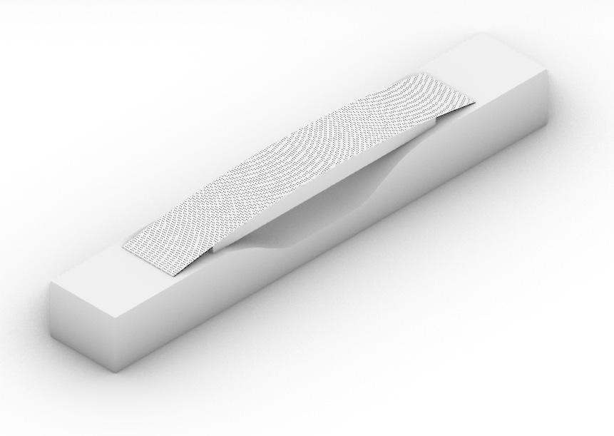
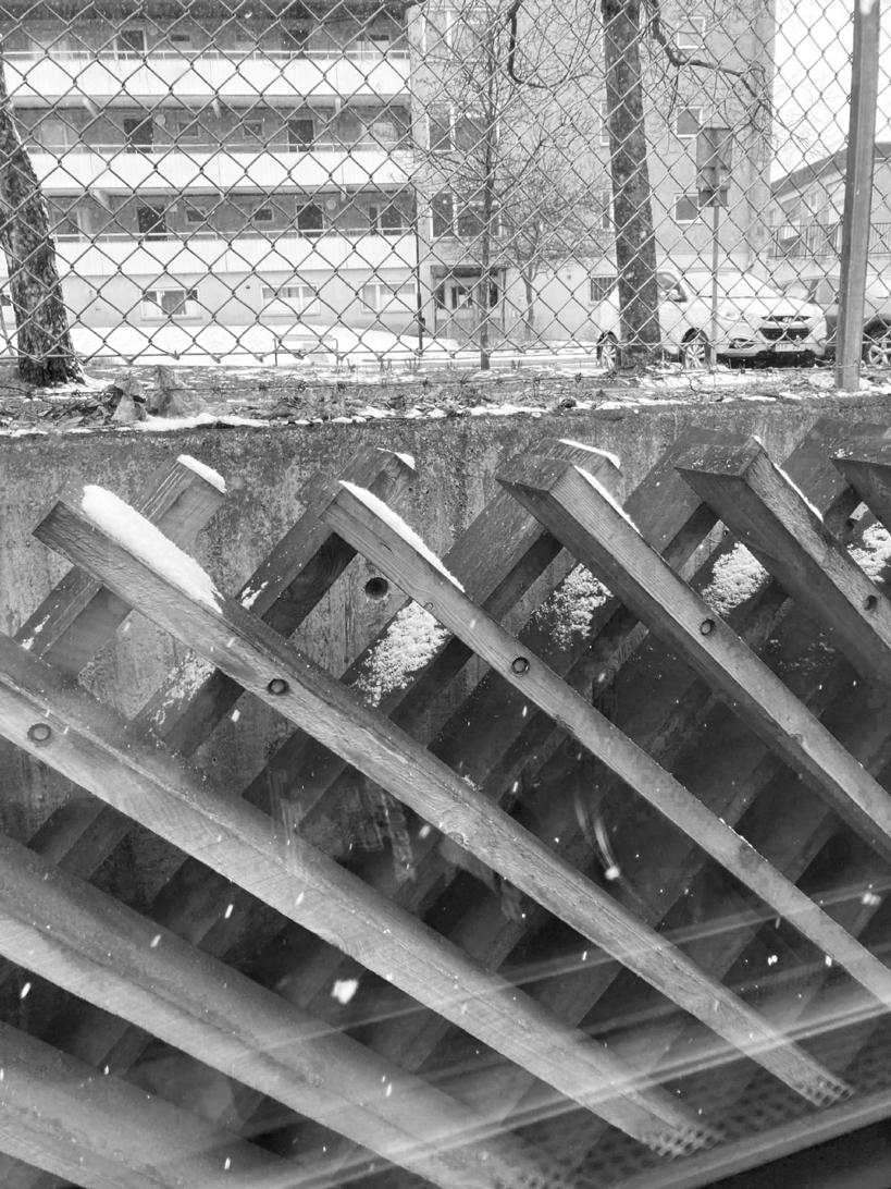
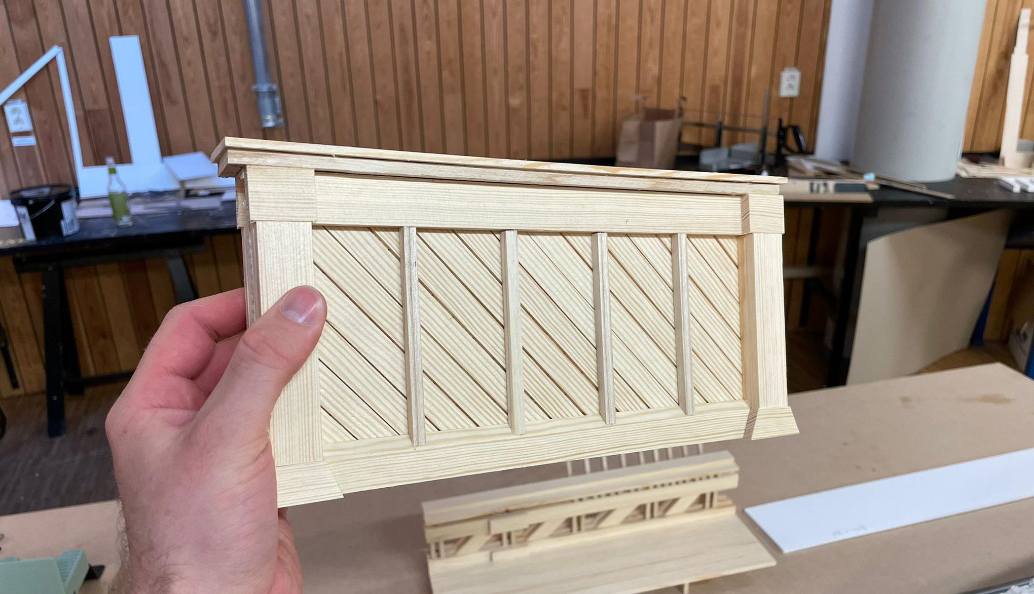
Our initial design iterations despite having potential, did not satisfy all 3 principles at first and work was not progres sing as planned. On a Sunday I took a subway ride and suddenly the above pictured decorative pattern appeared on the side of the train. The arrangement of the wooden planks reminded me of a 1800s English Garden and sparked the idea that we developed until the rest of the term. Initially we thought that a curved deck would still be possible and explored that idea once again.
Version 4 Side Elevation
Subway Inspiration
Tunnelbana Wood Panels Covering the Concrete Walls
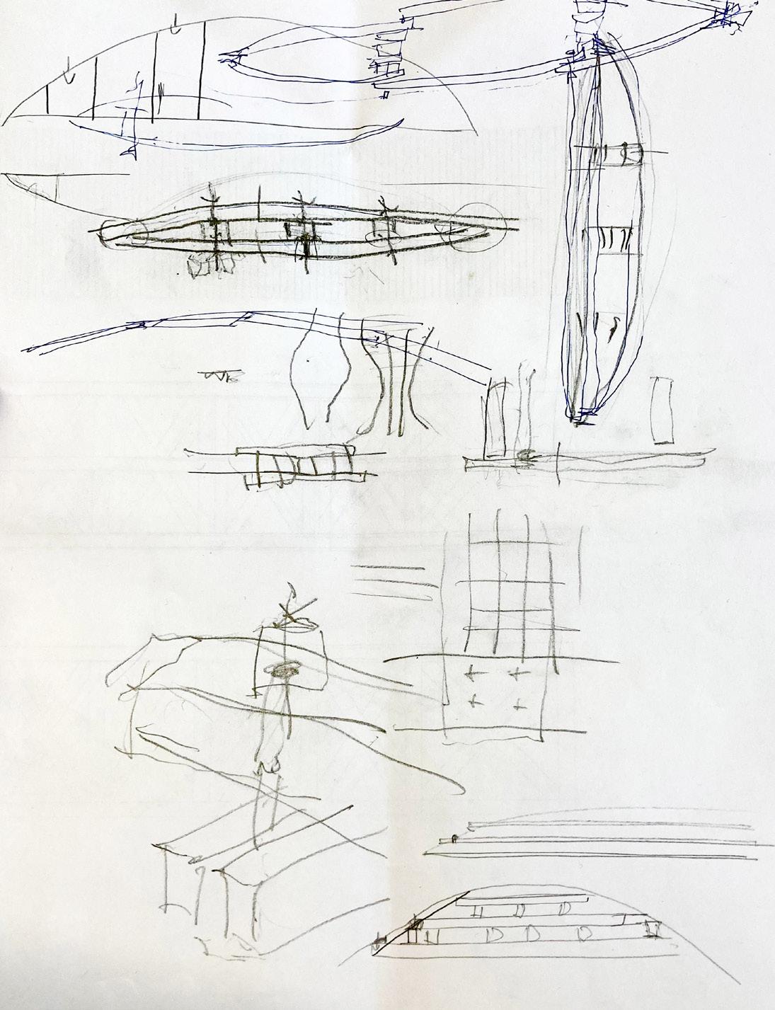
Version 1 Sketches
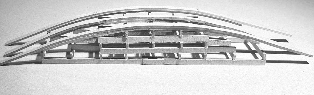
Version 3 (Combined Concepts) Sketch Model
Garden Bridge 8 82
Version 1 Sketch Model
Version 3 (Combined Concepts) Section & Detail Sketches
Version 4 Floor Plan
Section B-B
Section A-A perspective
Section B-B perspective
Version 5 Axo Transverse Section
Version 5 Axo Longitudinal Section
Garden Bridge 9 82 Vectorworks Educational Version Vectorworks Educational Version
Section B-B
Design Development
Section A-A
Version 5.1 Front Elevation Version 5.1 Side Elevation Version 5.2 Front Elevation Version 5.2 Side Elevation Version 5.3 Front Elevation Version 5.3 Side Elevation
Vectorworks Educational Version perspective
Version 5 Axo Floor Plan Version 5 Axo
Section B-B perspective
Version 5 Floor Plan Structural Truss Sketch Model
In the process of exploring the crossed diagonals, we agreed that a simple truss would be best for the structure and it would satisfy two of the principles - to have a protected structure from the elements and to create an elevated plat form for the viewer. That is when the exploration of the aesthetical process also began, we explored different variati ons of railing systems to mimic best a 1800s English Garden feel for the bridge. The outcomes were successful, but the final design was not quite there.
Railing Shape and Bottom Truss Detail Sketch
Review FLOOR PLAN M 1:10 ISOMETRY // with covering 10,45 sectionB-B sectionA-A B-Bsection 98201,07201,07201,07201,07201,0720 98 10,45 1,07201,0720 FLOOR PLAN M 1:10 ISOMETRY // without covering B-Bsection section sectionA-A
In the midterm review our design was more or less the almost final form of the bridge. The railing, however, was still not quite there yet. In order to truly mimic that 19th century English Garden feel we decided to explore using thinner elements such as 45 by 45 pieces that we had available to us and position them strategically to “hide” the structure. The stairs also needed a bit of an adjustment, as the slope was too steep for pedestrians. Additionally, in conversations and further static modelling, we discovered that only bracing on the top of the truss will be sufficient. And lastly, we remodelled the angle of the diagonals of the trusses in order to accomodate for more comfortable stairs.
Garden Bridge 10 82
Midterm
6 Floor Plan at Railing Bottom Truss Detail Railing Detail 1 Version 6 Floor Plan at Deck Railing Detail 2 Railing Detail 3 Version 6 Longitudinal Section Top of Stairs DetailVersion 6 Front Elevation Side VersionElevation6Transverse Section
Version
Truss and Railing Details Sketches
Moment Model of Truss
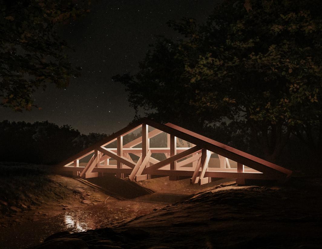
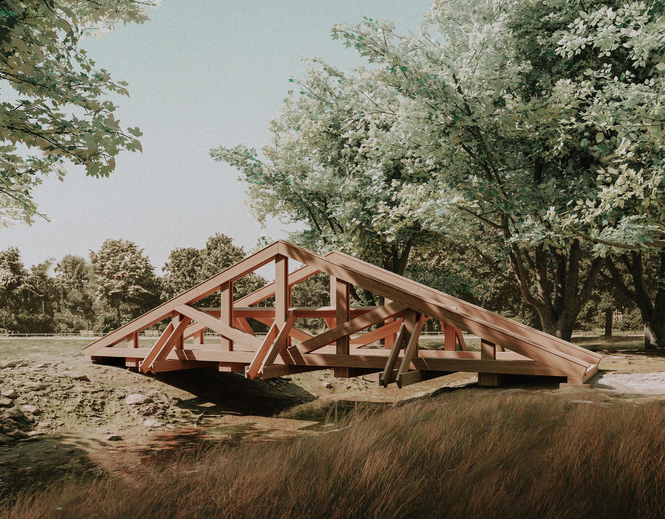
Deck View Render
Garden Bridge 11 82
Bridge Side View Render Axo

Stress Model of Truss
Deformation Model of Truss
Diagonal View Sketch Model
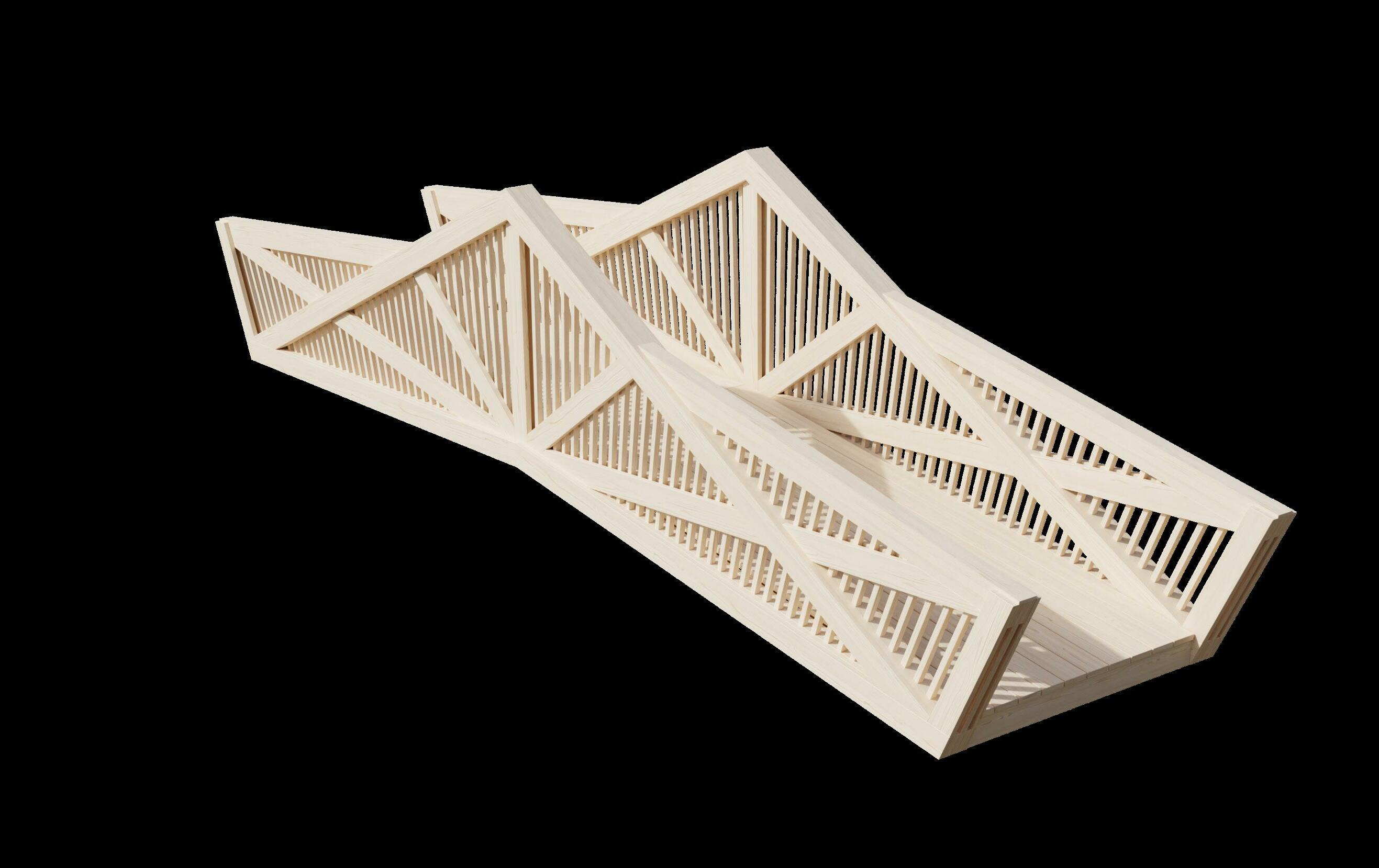
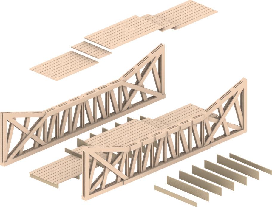
Exploded
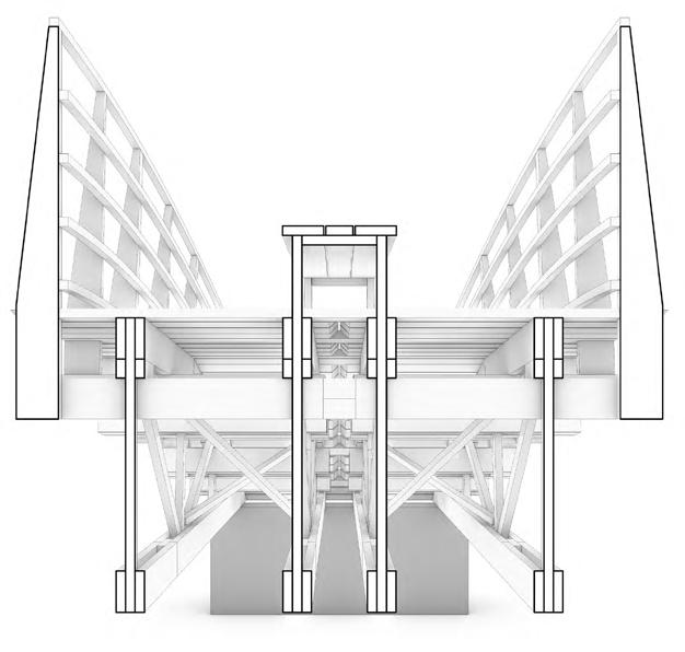
Frontal View Sketch Model
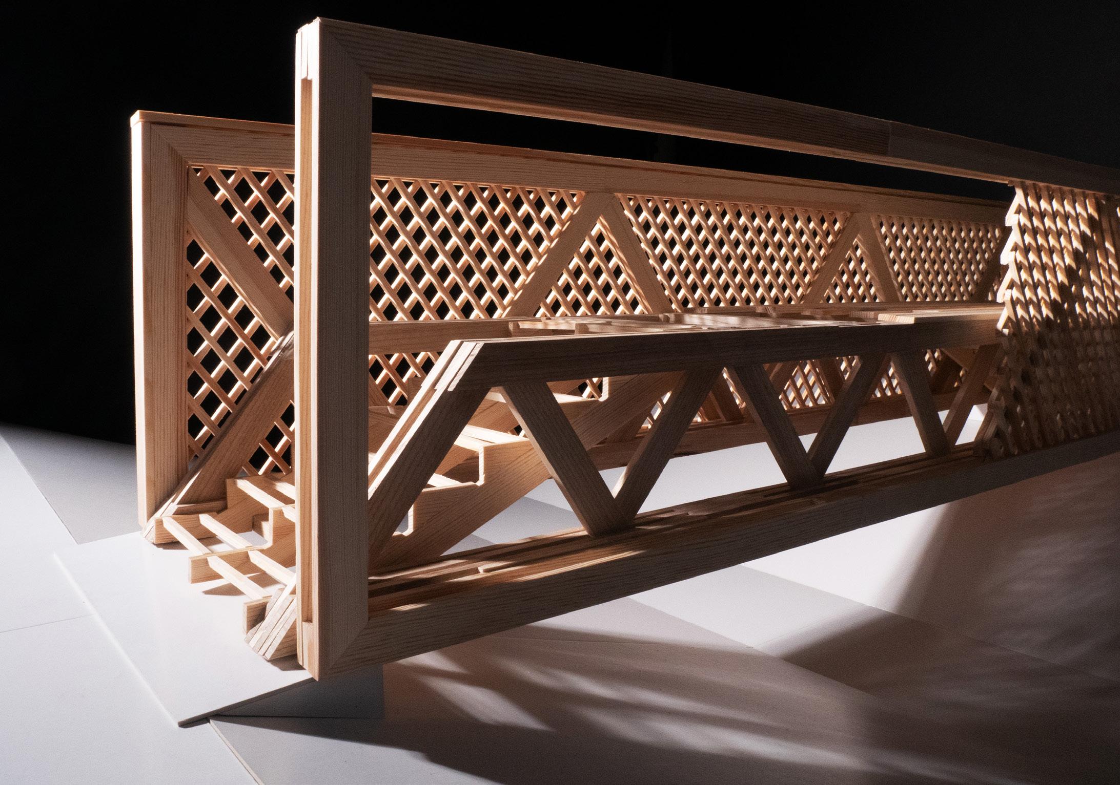
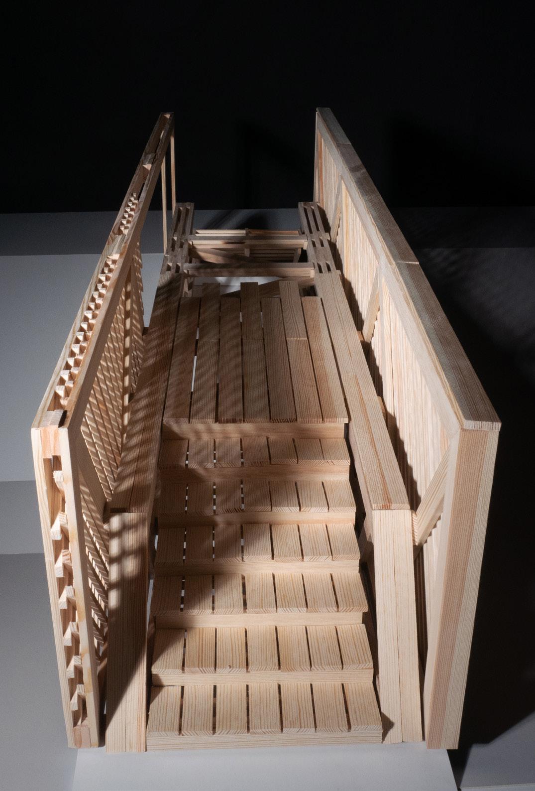
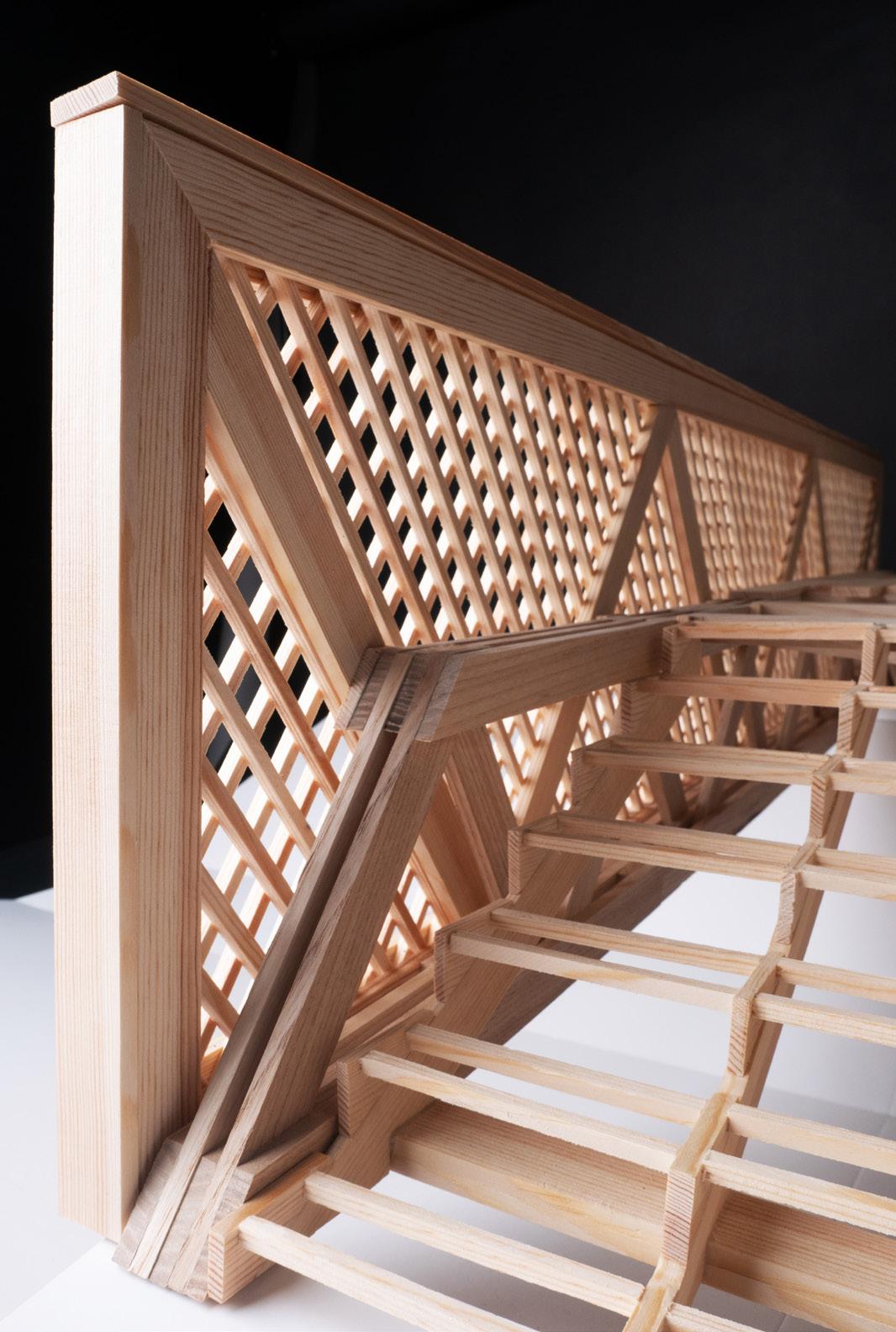
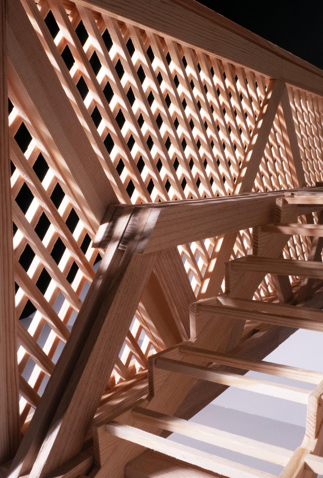
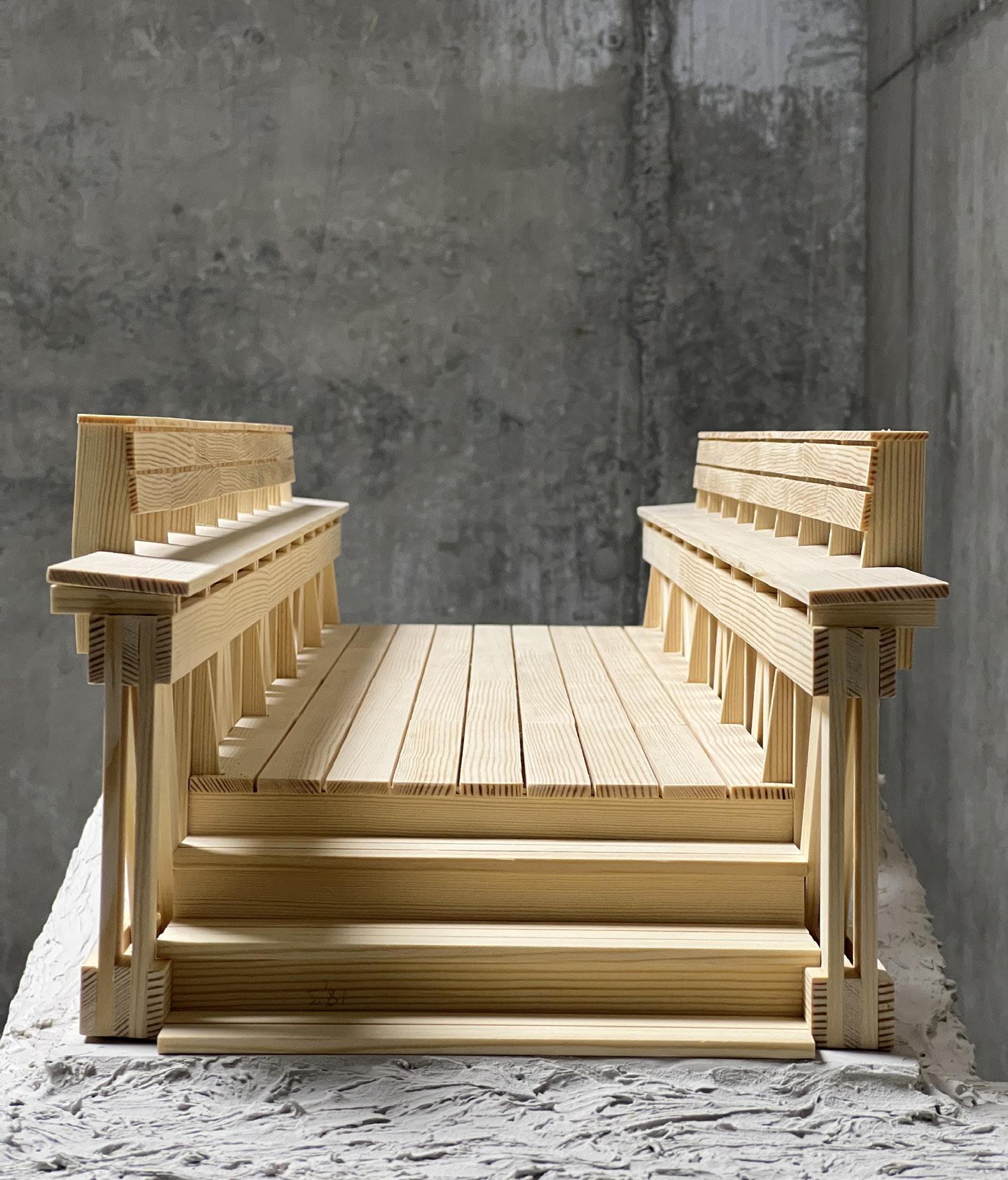
The finished bridge perfectly embodied our core design principles. We successfully created a railing that could be easily replaced, while also being aesthetically pleasing. Not only that but we playfully mimicked the structural truss diagonals to create beautiful and harmonious motifs and also “hide” the structure perfectly, appearing as if the railing plays a role in supporting the bridge, which could not be further from the truth. The end result was a perfectly structu rally stable bridge, with a well protected from the elements structure, and railing screens that call out to the pedestri ans to invite them and provide a serene experience while viewing nature.
Garden Bridge 12 82


Front

Finished Design 2380mm2000mm5614.8mm10000mm 1200mm1200mm Floor Plan 1 Floor Plan 2 Section AA Axo Section BB Axo Section AA Section BB
Elevation Side Elevation A ABB Floor Plan2 Floor Plan1


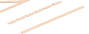
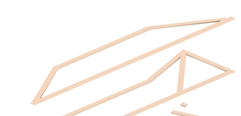
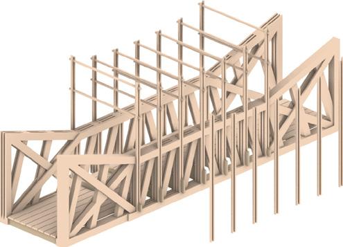
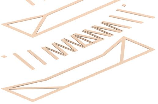
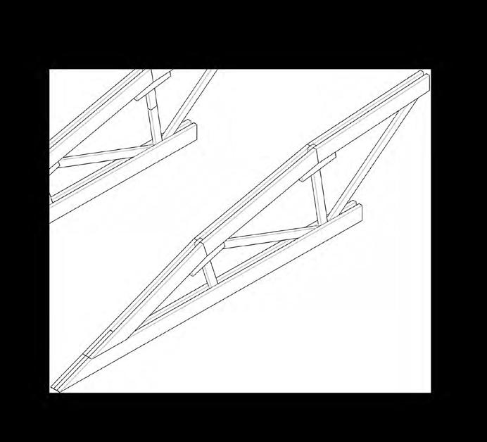
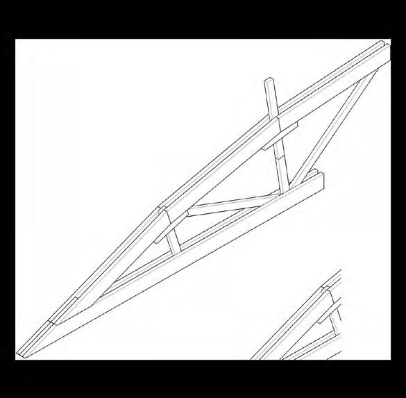
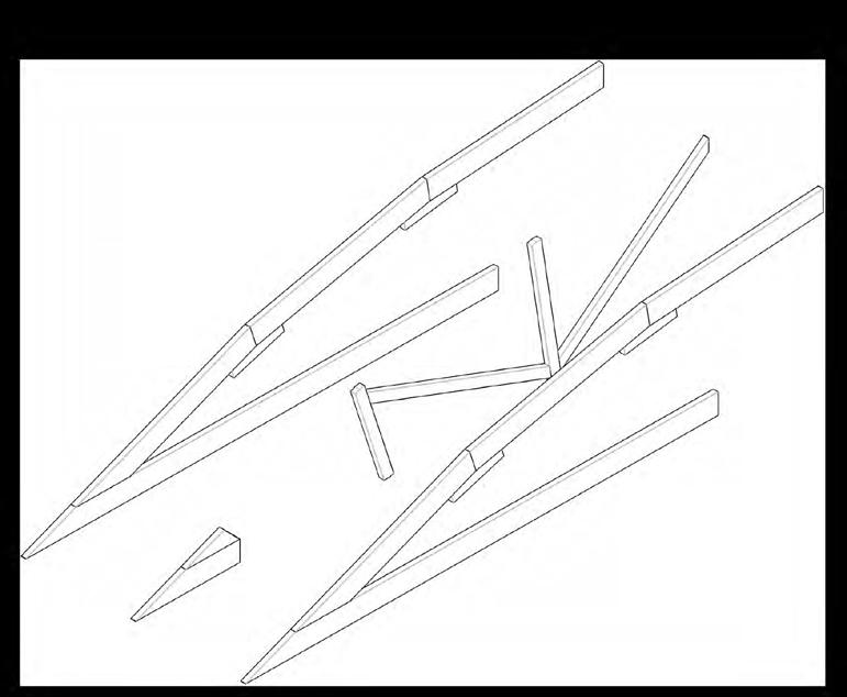
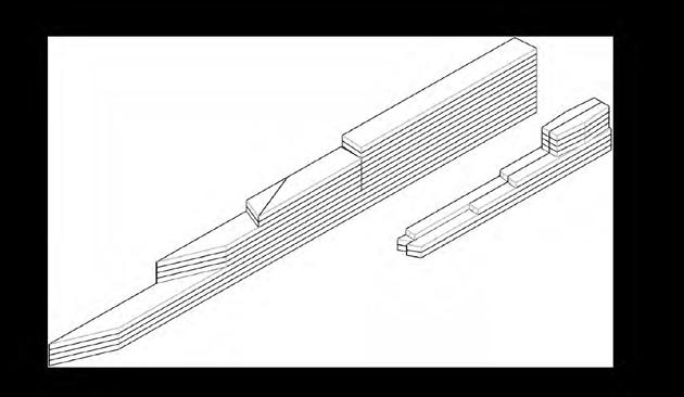
As the proposal was supposed to be built physically, we created an IKEA-like building instructions of how each indivi dual component comes together, what each major element is supposed to look like and how they all come together to form the finished bridge. We also included details of different important parts to show how they are joined to one another. Building the Bridge Construction Diagram Axonometric
Garden Bridge 13 82
Assembly
Railings Parts & Assembly
Trusses
Garden Bridge 14 82 1 4 5 x68x12x16x12x12x6x6 x12x128x14x8x24x4 x8
Railings Parts & &
Assemblyx8x2x16x8x4x8x16x16x20x20x2x2x2x2x104x16x36x8x8x8x8x8x8x8 Trusses Parts
Parts & Assembly 2 1 3
Garden Bridge 15 82 2 3 6 7 4 6 5 7
2 Bottom Truss and Railing Joining Detail
Railing Detail
Railing
Detail 1 Bracing Detail
Garden Bridge 16 82 2 4 Stairs Parts & Assembly x6x56x84x36x6x12x108x332 Bracing 1 3 Stairs Parts & Assembly
Garden Bridge 17 82 x2x2x7x28x112 x2x4x8x8x3x6 Bracing Parts & AssemblyDeck Parts & AssemblyBracing Parts Deck Parts & Assembly

Stairs Detail 2
Stairs Detail 1
Often times one sees only the finished product of an architectural design, without seeing the engineers work in making the design come to life. Therefore, we decided to let the reader in on the important work that goes behind the scenes in the form of computer generated models and static calculations done by our engineering collegues.

DeformationNormalMomentForceForce
Garden Bridge 18 82
Behind the Scenes Engineers Work
Shear
Page 2 of Static Calculations
Garden Bridge 19 82
Page 1 of Static Calculations
Page 3 of Static Calculations
Page 4 of Static Calculations
Garden Bridge 20 82
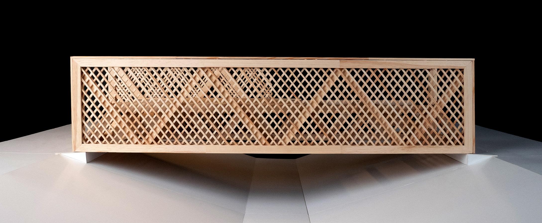
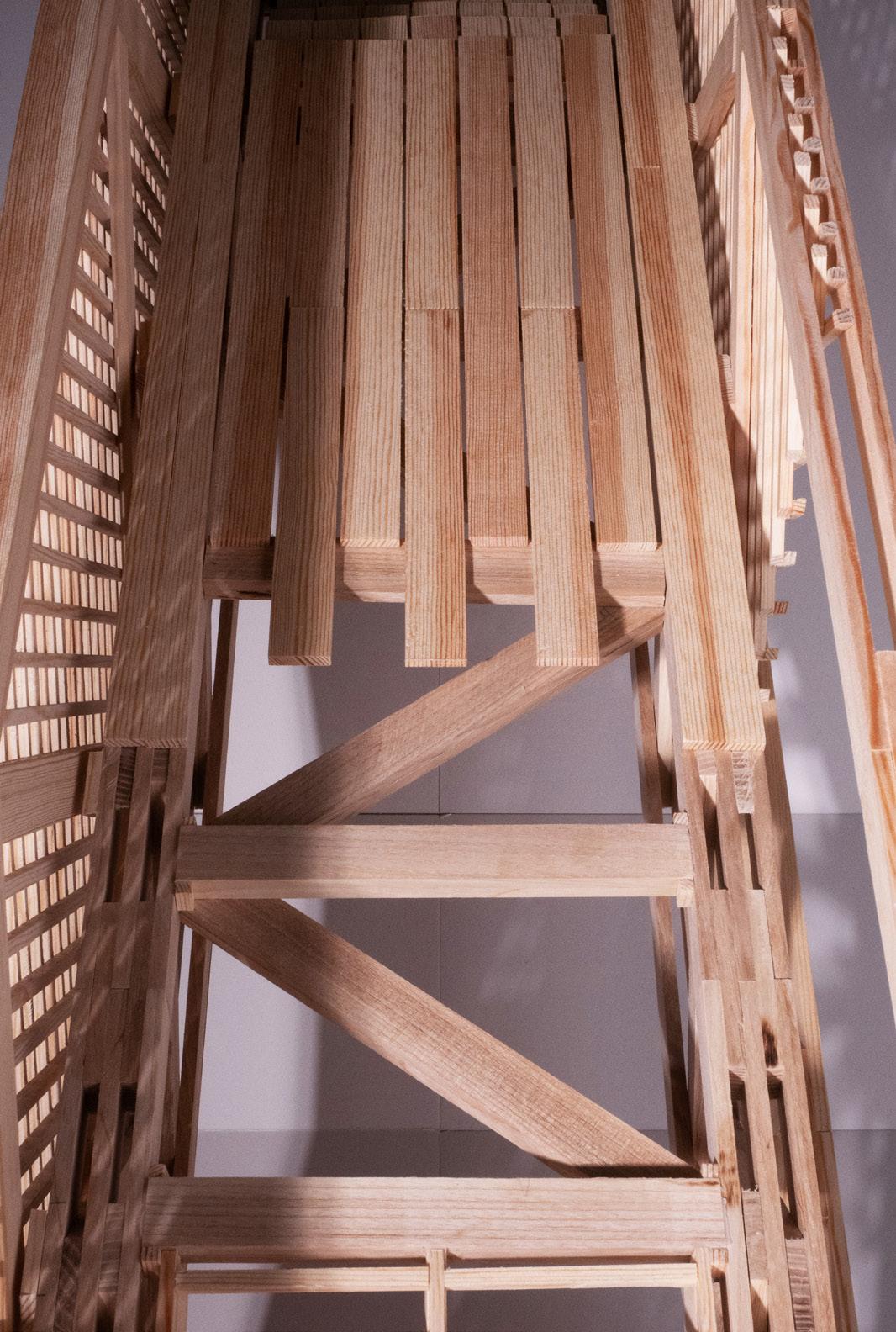
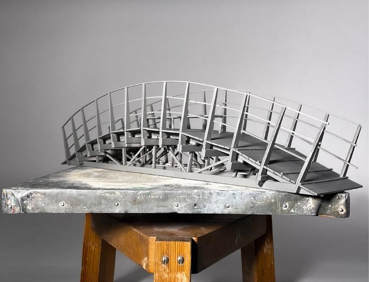
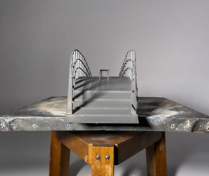
Hand-Made Model from Pine and Wallnut Wood
Garden Bridge 21 82
Garden Bridge 22 82
Garden Bridge 23 82
Project 2 Architecture Albin Jonsson Sarah Coltier Dani Georgos Architecture HTW Silke CorinnaMartinHeller Engineering Yasir ClemenceCharlotteZahidJägerBaud 21.8°
Concept
Our focus in this project was to create a simple design where the construction get to be the strong charachter of the bridg. But also simple design as it going to be build by student we wanted to make it as easy build as possible.
21.8° 25 82
Our biggest chalange was the railing. As the truss was the importent peise in our design we wanted the railing to be simple so that the truss get to be the center of etention.
21.8° 26 82
The designing process started with a triangler/diamont shape that had a traditional construction sulotion with a simple twist to it. Under the process to reach i unic design we kept us to the triangle truss shape.
ConceptConcept
Railing
As the Truss is quite hight we needed to add side support for the stabilisation of the truss. We come to a conclution where we atatch the railing to the side support as original solution. The railing is places only in the middle of the bridg inbetwen the sides of the triangle to give the triangle a clean shape. We imagine the railing to act as a leaning benshes where you can stand and watchout to the nature thru the bug truss opening.
21.8° 27 82
Final design
21.8° 28 82 Drawings 500 1000 500 1000
21.8° 29 82 500 1000 500 1000
21.8° 30 82 D F C C E G D2 E3 A7 B8 A3A2A1 B2B1 A4A5A6 B3B4B5B7B6 D1 (45x45) G C2 E1E2E4 (100x200)(100x200)F C1D2 E3 A7 B8 A3A2A1 B2B1 A4A5A6 B3B4B5B7B6 D1 (45x45) G C2 E1E2E4 (100x200)(100x200)F C1 D2 E3 A7 B8 A3A2A1 B2B1 A4A5A6 B3B4B5B7B6 D1 (45x45) G C2 E1E2E4 (100x200)(100x200)F C1D2 E3 A7 B8 A3A2A1 B2B1 A4A5A6 B3B4B5B7B6 D1 (45x45) G C2 E1E2E4 (100x200)(100x200)F C1 D2 E3 A7 B8 A3A2A1 B2B1 A4A5A6 B3B4B5B7B6 D1 (45x45) G C2 E1E2E4 (100x200)(100x200)F C1 Building part D2 E3 A7 B8 A3A2A1 B2B1 A4A5A6 B3B4B5B7B6 D1 (45x45) G C2 E1E2E4 (100x200)(100x200)F C1
21.8° 31 82 Building part x6 A1 A5 x2x4x2x4 A2 B2 A2 B4 A3 B5 A3 B4 A4 x2x3x2x1x2 B1 B1 B1 B1 B1 B3 B3 B3 B3 B8B8B6 B1B6 B1 TRUSS 1 x1 B7 A6 A6 A6 x1 A7 A7 A7 A7 A7 A7 A7 A7 A7 A7 1 2 3 4 B1 B1MONDAYSUPPORT x6 A1 A5 x2x4x2x4 A2 B2 A2 B4 A3 B5 A3 B4 A4 x2x3x2 B1 B1 B1 B1 B1 B1 B1 TRUSS 2 x1 B7 A6 A6 A6 x1 A7 A7 A7 A7 A7 A7 A7 A7 A7 A7 1 2 3 4 B1 B1SUPPORTTUESDAY x7 D1 D1 CROSS BEAMS + RAILING x3 1 2 3 4WEDNESDAY D2 D2 x6 C1 x4 C2C2 C2 x4 G1 100x200 FLOORING x12 E1 x6 E2 x6 E3 E4 x1 S1 S1 S1 S1 S1 S1 S1 S1 S1 S1 x2 S2 x2 S3 S3 S2 S4 S4 x1 S1 S1 S1 S1 S1 S1 S1 S1 S1 S1 x2 S2 x2 S3 S3 S2 S4 S4 x1 F1 F1 100x200 x2x1 B3 B3 B3 B3 B8B8B6 B6 SUPPORT 1 2THURSDAY Y5 Y5 Y4Y4Y4Y4 Y3Y3 Y2Y2 Y1Y1Y1Y1 5x 1200120012001200 24002400 12001200120012001x2x2x2x100x200100x200200x200200x20045x195 24002400 24002400 MONDAY TUESDAY WEDNESDAY THURSDAY FRIDAY MORNING Briefing Briefing Briefing Briefing Cleaning + installation of workstations (A7x10) +(A1x6) + (A5x6) + (B8x4) (A3x6) + (A2x6) + (A4x3) + (A6x3) + (B1x16) Lift + Assembly bracing & support to truss 1 (B7x2) + (B6x4) + (B3x4) + (B5x4) + (B4x4) + (B2x4) (D1x14) + (G1x4) + (E2x6) (D2x6) + (C1x6) + (E1x12) (C2x12) + (E3x6) + (E4x6) Lift + Assembly bracing & support to truss 2 Assembly C1 & C2 to the truss + Detach A-frame support (Y1x8) + (Y2x4) + (Y3x4) + (Y4x4) + (Y5x10)
(A7x10) +(A1x6) + (A5x6) (A3x6) + (A2x6) + (A4x3) + (A6x3) Marking floor + (B1x16) + (B2x4) + (B8x4) (B7x2) + (B6x4)
+ (B3x4) + (B5x4) + (B4x4) LUNCH AFTERNOON Place layer 1 & 2 + (S3x4) Place layer 3 & 4 + (S2x2) + (S4x4) & (S1x10) + Place layer 5 + screw Moving truss 1 outside Moving truss 2 outside + Cleaning Assembly C2 + E1, E2, E3 & E4 + G1 Assembly support (Y pieces) & Lifting the bridge on the suports Place layer 1 & 2 + (S3x4) Place layer 3 & 4 + (S2x2) + (S4x4) (S1x10) + Place layer 5 + screw (F1x2) 14h40 : Presentation Cleaning Cleaning Cleaning + Apéro OBJECTIVE OF THE DAY • Truss 1 cut and assembled • Bracing and support pieces for truss 1 cut • Truss 1 outside with bracing • Truss 2 cut and assembled • Bracing and support pieces for truss 2 cut • Truss 1 & 2 outside with bracing • All cross beams and railing pieces cut • All flooring pieces cut • Bridge completed 123413h3012h309h0016h30 1 2 43 11234324 1234 11122 2 B4B1 & B5 B2 B1 B8 A2 & A3A3 A2
Layer 4 2 pcs 2 pcs 8 pcs
Layer 1 1 pcs 1 pcs 2 pcs 2 pcs 2 pcs 2 pcs A5A4A3A2A1A6
Layer 2 2 pcs 2 pcs 8 pcs
11013 5930 2203
Truss : Ground outlineTRUSS OUTLINE FOR FLOOR 10 pcs A7 2 pcs B8 2 pcs B8
A5A4A3A2A1A6
B1B2B3B4B5B6B71 pcs 2 pcs 2 pcs 2 pcs
21.8°
Layer 1 1 pcs 1 pcs 2 pcs 2 pcs 2 pcs 2 pcs
Layer 3 1 pcs 1 pcs 2 pcs 2 pcs 2 pcs 2 pcs
21.8° 32 82 Bridge Assembly Manual 2021/22
B1B2B3B4B5B6B71 pcs 2 pcs 2 pcs 2 pcs 2 pcs 2 pcs A2A110 pcs A7 2 pcs B8
Layer 2 2 pcs 2 pcs 8 pcs
B1B2B3B4B5B6B71 pcs 2 pcs 2 pcs 2 pcs
Layer 3 1 pcs 1 pcs 2 pcs 2 pcs 2 pcs 2 pcs A5A4A3A2A1A6
Studio Applied Architecture
A5A4A3A2A1A6
Note : Use this plan to firstly draw
the outlines on the ground. Dimensions follow the projected perimeter of the pieces
21.8° 33 82 Truss : Layer 1
Note : Use this plan to place the pieces on top of Layer 1. In this layer, dimensions follow the distance in between the pieces Truss : Layer 2 Material : A3 A7A7 A7A7A7A7A7A7A7 A7 B8B8 A2 A1 A2 A1 A4 A3A3 A5 A5 A6 B1 B1 B1 B1 B1 B1 B2B2 B1B1 B3B3 B7 B6 B5 B4B6B5B4A2 A1 A2 A1 A4A3 A5 A5 A6 240 101 101 135135 357 10551055 105510551055 1055 10000 1250125012501250 12501250 10551055 1055 2000 10551055 1055 1250 1250 135135
10 pcs A7 2 pcs B8 2 pcs B8
A3 A7A7 A7A7A7A7A7A7A7 A7 B8B8 B8B8 A2 A1 A2 A1 A4 A3A3 A5 A5 A6 B1 B1 B1 B1 B1 B1 B2B2 B1B1 B3 B7 B6 B5 B4B6B5B4A2 A1 A2 A1 A4A3 A5 A5 A6 B1 B1 B1 B1 B1 B1 B2 B1B1 B3 B7 B6 B5 B4B6B5B4 A1 A1 240 101 101 101 101 135135 135135 357 10551055 105510551055 1055 240 10000 1250125012501250 12501250 10551055 1055 2000 10551055 1055 10551055 105510551055 1055 1250 1250 135135
B8
:
Layer 2 2 pcs 2 pcs 8 pcs B1B2B3B4B5B6B71 pcs 2 pcs 2 pcs 2 pcs
Layer 4 2 pcs 2 pcs 8 pcs B1B2B3B4B5B6B71 pcs 2 pcs 2 pcs 2 pcs
Layer 5 1 pcs 1 pcs 2 pcs 2 pcs 2 pcs 2 pcs A5A4A3A2A1A6
Layer 4 2 pcs 2 pcs 8 pcs B1B2B3B4B5B6B71 pcs 2 pcs 2 pcs 2 pcs
Layer 1 1 pcs 1 pcs 2 pcs 2 pcs 2 pcs 2 pcs A5A4A3A2A1A6
Layer 3 1 pcs 1 pcs 2 pcs 2 pcs 2 pcs 2 pcs A5A4A3A2A1A6
Layer 5 1 pcs 1 pcs 2 pcs 2 pcs 2 pcs 2 pcs A5A4A3A2A1A6 10 pcs 2 pcs 2 pcs
central axis of the pieces Material
Layer 2 2 pcs 2 pcs 8 pcs B1B2B3B4B5B6B71 pcs 2 pcs 2 pcs 2 pcs
to place the pieces on the ground outlines. In this layer, dimensions follow
Note Use this plan the :
Layer 1 1 pcs 1 pcs 2 pcs 2 pcs 2 pcs 2 pcs A5A4A3A2A1A6
B8
Layer 3 1 pcs 1 pcs 2 pcs 2 pcs 2 pcs 2 pcs A5A4A3A2A1A6
A7
Layer 5 1 pcs 1 pcs 2 pcs 2 pcs 2 pcs 2 pcs A5A4A3A2A1A6
Layer 3 1 pcs 1 pcs 2 pcs 2 pcs 2 pcs 2 pcs A5A4A3A2A1A6
Layer 2 2 pcs 2 pcs 8 pcs B1B2B3B4B5B6B71 pcs 2 pcs 2 pcs 2 pcs
21.8° 34 82 Note : Use this plan to place the pieces on top of Layer 2. In this layer, dimensions follow the distance in between the pieces Material :Truss : Layer 3 A3 A7A7 A7A7A7A7A7A7A7 A7 B8B8 B8B8 B1 B1 B1 B1 B2B2 B1B1 B3B3 B7 B6 B5 B4B6B5B4A2 A1 A2 A1 A4A3 A5 A5 A6 B1 B1 B1 B1 B1 B1 B2B2 B1B1 B3B3 B7 B6 B5 B4B6B5B4A2 A1 A2 A1 A4 A3A3 A5 A5 A6 240 101 101 101 101 135135 135135 357 10551055 105510551055 1055 240 10551055 1055 10551055 1055 10551055 1055 10551055 1055 10551055 105510551055 1055 135135 10 pcs A7 2 pcs B8 2 pcs B8 2 pcs B6B71 pcs Layer 3 1 pcs 1 pcs 2 pcs 2 pcs 2 pcs 2 pcs A5A4A3A2A1A6

Layer 4 2 pcs 2 pcs 8 pcs B1B2B3B4B5B6B71 pcs 2 pcs 2 pcs 2 pcs
Layer 4 2 pcs 2 pcs 8 pcs B1B2B3B4B5B6B71 pcs 2 pcs 2 pcs 2 pcs
Layer 4
Layer 5 1 pcs 1 pcs 2 pcs 2 pcs 2 pcs 2 pcs A5A4A3A2A1A6
Layer 1 1 pcs 1 pcs 2 pcs 2 pcs 2 pcs 2 pcs A5A4A3A2A1A6
Note : Use this plan to place the pieces on top of Layer 3. In this layer, dimensions follow the distance in between the pieces Truss : Layer 4 A3 A7A7 A7A7A7A7A7A7A7 A7 B8B8 B8B8 A2 A1 A2 A1 A4 A3A3 A5 A5 A6 B1 B1 B1 B1 B1 B1 B2B2 B1B1 B3B3 B7 B6 B5 B4B6B5B4A2 A1 A2 A1 A4A3 A5 A5 A6 B1 B1 B1 B1 B1 B1 B2B2 B1B1 B3B3 B7 B6 B5 B4B6B5B4A2 A1 A2 A1 A4 A3A3 A5 A5 A6 240 101 101 101 101 135135 135135 357 10551055 105510551055 1055 240 10000 1250125012501250 12501250 10551055 1055 10551055 1055 10551055 1055 2000 10551055 1055 10551055 105510551055 1055 1250 1250 135135
Layer 5 1 pcs 1 pcs 2 pcs 2 pcs 2 pcs 2 pcs A5A4A3A2A1A6
Material : 10 pcs A7 2 pcs B8 2 pcs B8
2 pcs B8 2 pcs 2 pcs B2B3B4B5B6B71 pcs 2 pcs 2 pcs 2 pcs
21.8° 35 82 A3 A7A7 A7A7A7A7A7A7A7 A7 B8B8 B2B2 B1B1 B7 B6 B5 B4B6B5B4A2 A1 A2 A1 A4A3 A5 A5 A6 B1 B1 B1 B1 B1 B1 B2B2 B1B1 B3B3 B7 B6 B5 B4B6B5B4A2 A1 A2 A1 A4 A3A3 A5 A5 A6 240357240 10551055 1055 10551055 105510551055 105510551055 1055 A3 A7A7 A7A7A7A7A7A7A7 A7 B8B8 B8B8 A2 A1 A2 A1 A4 A3A3 A5 A5 A6 B1 B1 B1 B1 B1 B1 B2B2 B1B1 B3B3 B7 B6 B5 B4B6B5B4A2 A1 A2 A1 A4A3 A5 A5 A6 B1 B1 B1 B1 B1 B1 B2B2 B1B1 B3B3 B7 B6 B5 B4B6B5B4A2 A1 A2 A1 A4 A3A3 A5 A5 A6 240 101 101 357 10551055 105510551055 1055 240 10000 1250125012501250 12501250 10551055 1055 2000 10551055 1055 1250 1250 Note : Use this plan to place the pieces on top of Layer 5. In this layer, dimensions follow the distance in between the pieces Truss : Layer 5 B8B8 B1 B1 B1 B1 B2B2 B1B1 B3B3 B7 B6 B5 B4B6B5B4A2 A1 A2 A1 A4 A3A3 A5 A5 A6 101 101 135135 240 10551055 1055 10551055 105510551055 105510551055 1055 Material : 2 pcs B8 2 pcs B6B71 pcs Layer 5 1 pcs 1 pcs 2 pcs 2 pcs 2 pcs 2 pcs A5A4A3A2A1A6 Truss : Layers joints positioning A B C1 C2 C3 E F K H2 J H1 G4 D4 G2 I2 G3 D3 G1 I1 L D1 D2 Note : See Annex 1 & Annex 2, at the end of the manual, for the screwing instructions and the details of each joint template (A-L).
8 x Ø6x200mm 4 x Ø6x200mm
ScrewsMaterial
Step 1 : Screwing truss layers
:
Screw Truss 1 layers in different joints while the truss is laying on the ground. Repeat for Truss 2. 50 x Ø9x200mm 12 x


A.Screw Truss
1 2 1 2 2 1
Truss 1 layers in different joints while the truss is laying on the ground. Repeat for
Step 1 : Screwing truss layers
21.8° 36 82 Material :
4 3 3 34 4 Screws
2. See screw template in Annex 1. 12 x Ø9x200mm 28 x Ø9x200mm
A. Ø9x200mm
S4 2 jacks
Step 2 : Fixing A-Frame & Transporting beams
1 S1 S1 S1S2 S4 S4 S3 2 12
S2 4
Step 1 : Screwing truss layers
6
Screw Truss 1 layers in different joints while the truss is laying on the ground. See screw template in Annex 1 & Annex 2. Repeat for Truss 2. 5 24 x Ø9x200mm 20 x Ø9x200mm 26 x Ø9x200mm 4 x Ø6x200mm 4 x Ø6x200mm5’56 6 5’ Screws 5 5’ 6 B.Place 2 transporting beams to the Truss 1. Use jacks to move the truss outside Snickarhallen. Repeat for Truss 2. A. Vertically raise truss with crane in Snickarhallen Place A-Frame support at the center of the Truss 1. Repeat for Truss 2. Material


S3 2
S4beamsTransportingA-FrameFixing 4
21.8° 37 82 Material :
S1 2
A. : pcs pcs pcs pcs pcs pcs
S1 2
21.8° 38 82
to the ground.
B.Place 200X200 support beams underneath the truss. Then place F1 pieces on top of each support beam. Lower the truss to rest on top of support beams. Then place random pieces holding A-frame to the ground.
Material : 2 pcs F1 2 pcs 200X200 2 pcs random leftovers
Support beams Support pieces 1 F1 F1 32 3 2 2

A.Repeat Step 3 Truss section place random A-frame
Cross section plan
Step 4 : Placing Truss 2 on support beams
pieces holding
A.Use jacks to raise the truss at about 35cm above ground.
18502300
for
Material : 2 pcs random leftoversSupport pieces 1 1
plan for distance positioning ). Then
DISTANCE BETWEEN TRUSSES
2 (See cross
Step 3 : Placing Truss 1 on support beams
21.8° 39 82

Step 5 : Connecting D1 beams
Material : 14 pcs D1ScrewsCrossbeams 21 D1 A.Screw D1 crossbeams pieces to Truss 1 and Truss 2 56 x Ø6x120mm

Step 6 : Connecting C1 & C2 beams
Material : 12 pcs C2 6 pcs C1ScrewsCrossbeams 312 C2 C2 C2 C1 C1 C1 A. Screw C1 to D1 crossbeams. Connect C2 to C1 and trusses. After C1 & C2 are connected, remove the A-frame support. Screw C1 & C2 at the center of the truss. 84 x Ø5x70mm
Step 8 : Flooring
21.8° 40 82 6 pcs D2Crossbeams 1 Material : Screws 2 24 x Ø9x200mm Step 7 : Connecting D2 beams A.Screw D2 diagonal cross beams to C1 ( See Cross beams plan ). Cross beams plan D2 C1 D2 E4 E3 E2 E1 E3 E1 E2 E3 E1 E2 E1 E1 E4 E4 E1 E1 E4 E4 E3 E2 E1 E3 E1 E2 E3 E1 E2 E1 E1 E4
A.Screw E1-E4 pieces to D1 crossbeams (See flooring plan and floorboard gapping). Flooring plan Floorboard gapping E1 E4 E2 E3 Material : 6 pcs E2 6 pcs E3 6 pcs E4 12 pcs E1ScrewsCrossbeams 51432 228 screws of Ø9x200mm
4 pcs Y2 : 200x200x2400
10 pcs Y5 : 45x195x2400
8 pcs Y1 : 200x200x1200
panelsProtectiveHandrails 54321
4 pcs Y4 : 100x200x1200
4 pcs Y3 : 100x200x2400
21.8° 41 82 Step 9 : Handrails A.Screw G1 pieces to C2 beams. Then place the protective panels on the outer top layer of the truss. Material : 4 pcs G1 16 pcsScrewspanelsProtectiveHandrails 321 24 screws of Ø6x120mm 22 C2 C2 C2 G1 G1 G1 C1 Y1 Y5 Y1Y1 Y1 Y3 Y3 Y4Y4 Y2 Y2 Step 10 : Bridge2XSupports A. Gradually build and place supports under the bridge with the help of jacks.


Material :
21.8° 42 82
21.8° 43 82

21.8° 44 82
21.8° 45 82
Engineering
Christoffer Baudou Janis FrankStainhauserVahstal
Bojan Covic Jakub Wright 84 Hands
Project 3
Architecture
Looking at the fact that this bridge is going to be build by a large group of students we decide this needs to be visible in the bridge. A bridge made by many hands.
The location is Järvafältet. Looking at this location we decide the bridge needs to become a desination in stead of just a bridge.
84 Hands 47 82
Location Concept
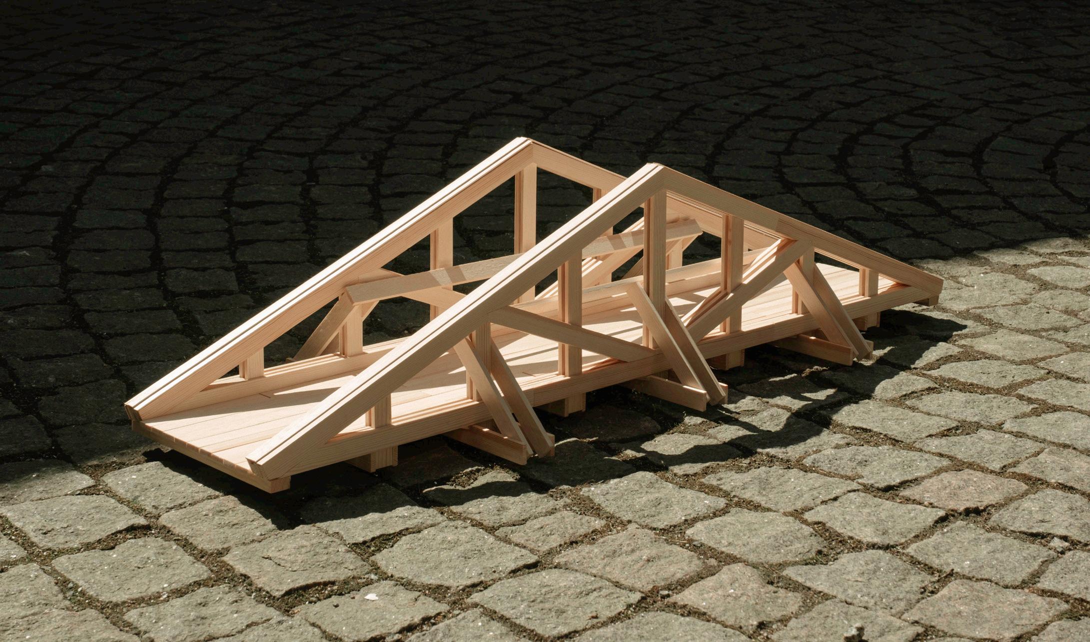
We tested the different trusses through quick 1-20 laser-cut models.

84 Hands 48 82
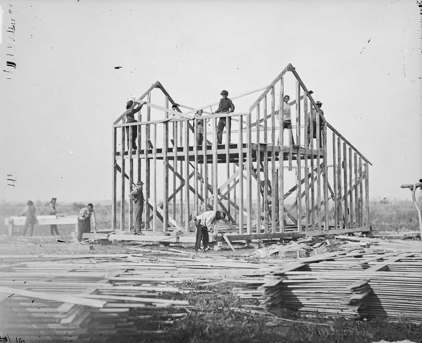
The combination of different systems was also the main characteristic of the Grubenmann brothers.
Concept
Throughout the process we had a strong urge to make this an exciting bridge. Looking at the structural concept we looked at different possibilities of creating this bridge for example a tie or a truss. For the final design we deci ded to combine these different.
Concept
Pergola
As mentioned before there was a desire to make this bridge more of destination in stead of a means to cross the water. Therefore we tested different ways to make the bridge more visible. Another option to make this bridge a destination is of course by giving it the possibili ty to have a seat.
84 Hands 49 82
84 Hands 50 82 Final Design
84 Hands 51 82 Final Design
84 Hands 52 82 2326 9804 2558 102000 4696 4703 3222 2849 2156 574 2 2 Building parts
84 Hands 53 82 2435 2147 1849 1807 1695 4602 2 2 26 6 6 2558 10 000 4718 4703 2869 2790 2158 574
84 Hands 54 82 2435 2147 1849 1807 1695 4602 2 2 26 6 6 2558 10 000 4718 4703 2790 574 2 2
84 Hands 55 82 2558 102000 4696 4703 3222 2849 2156 574 2 2 2100 10 000 3220 8 2570 16 825 16 2625 12 1740 4
84 Hands 56 82 Detailing

84 Hands 57 82 Steel plate Geka fastener
84 Hands 58 82 Geka fastener

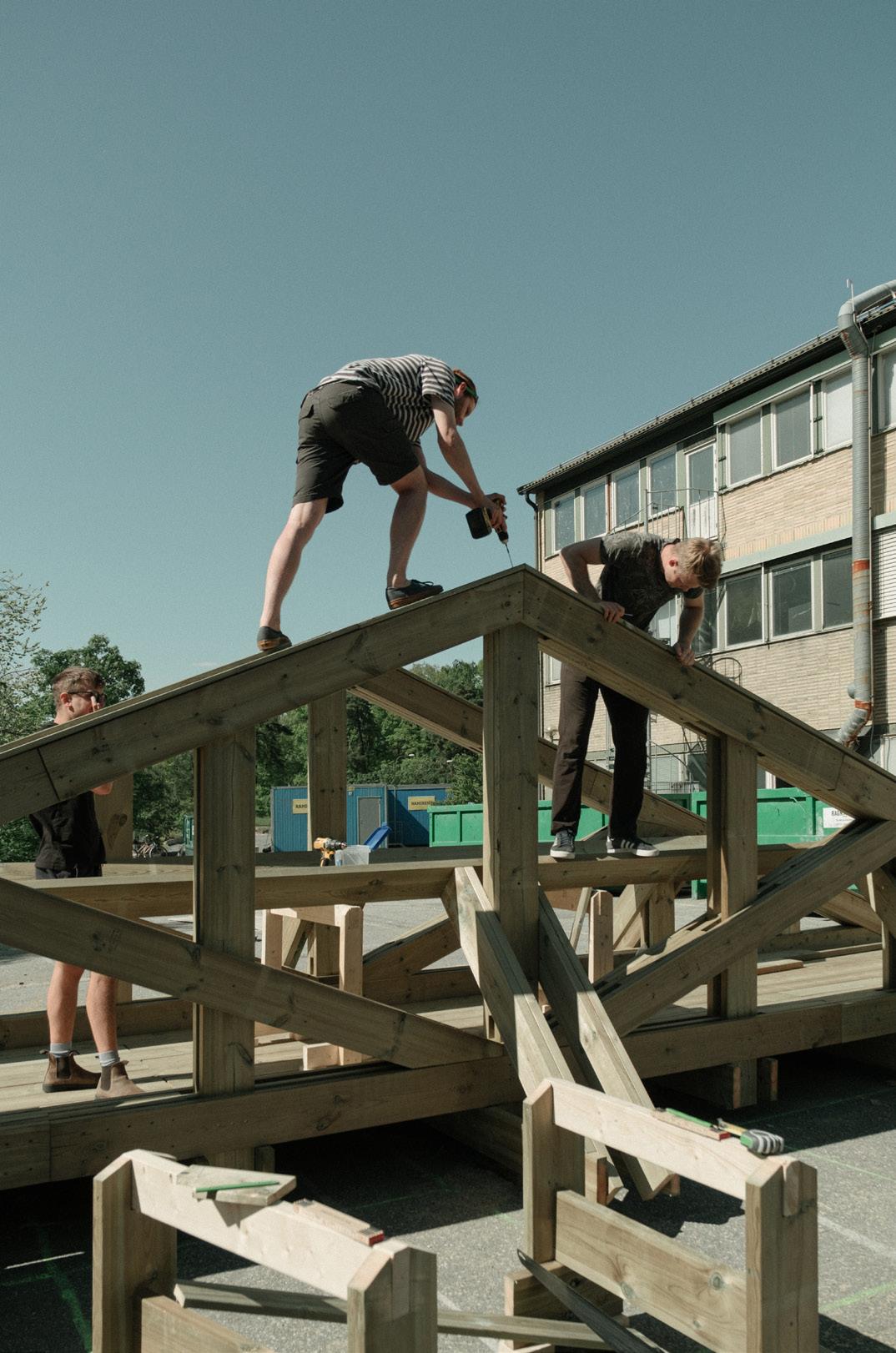
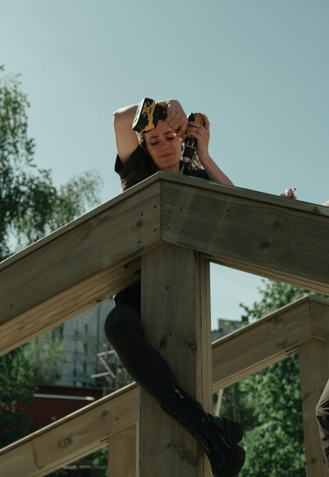
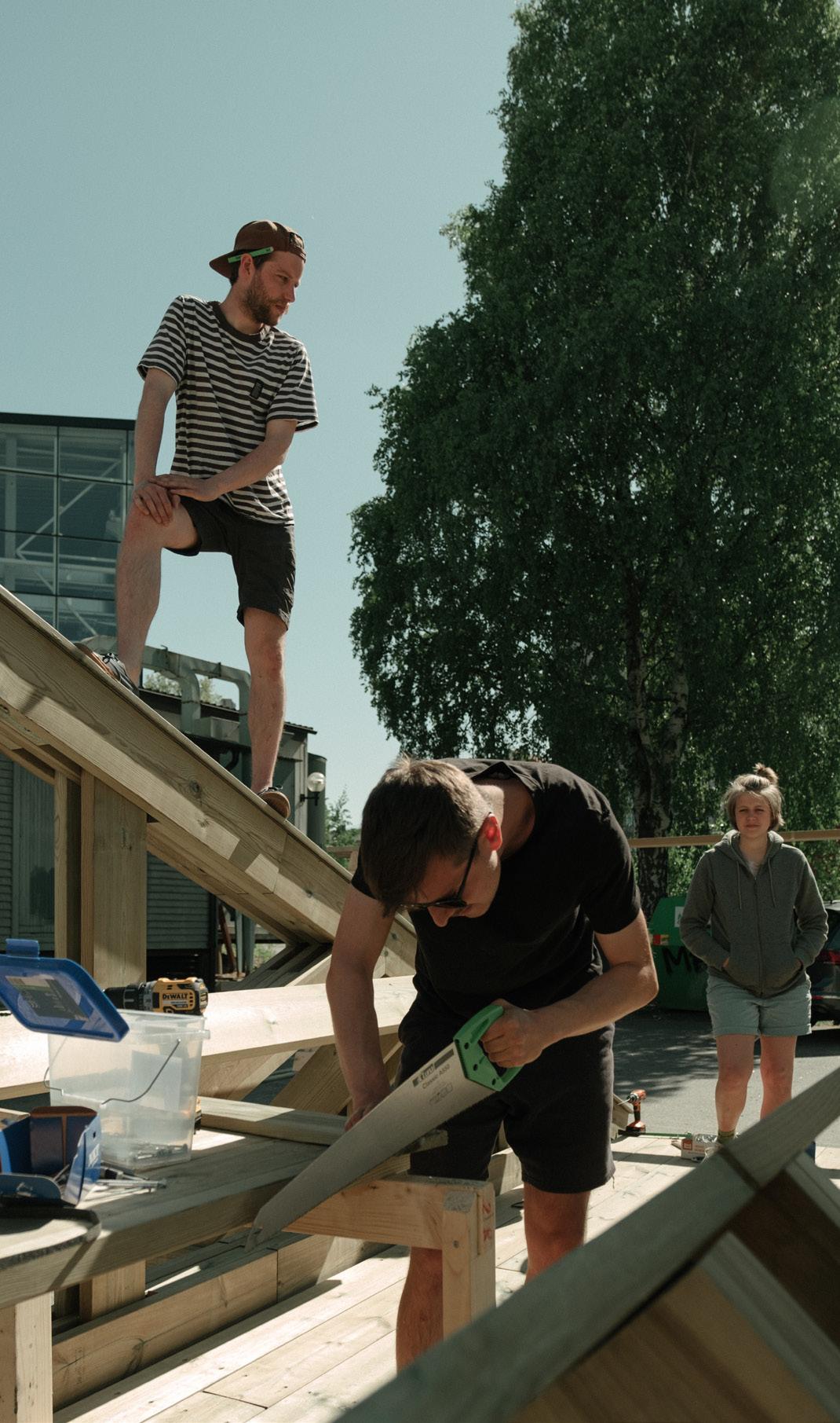
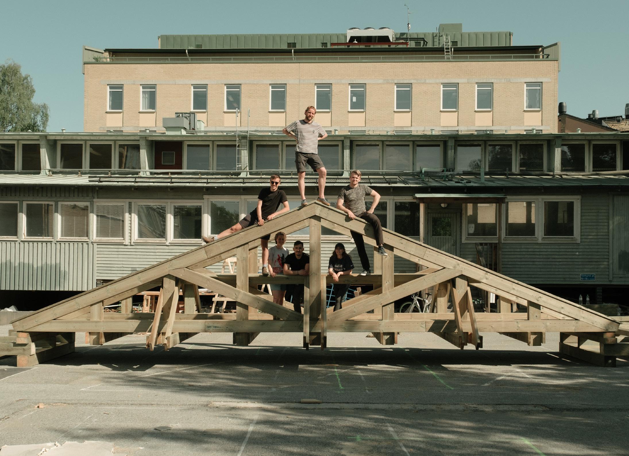
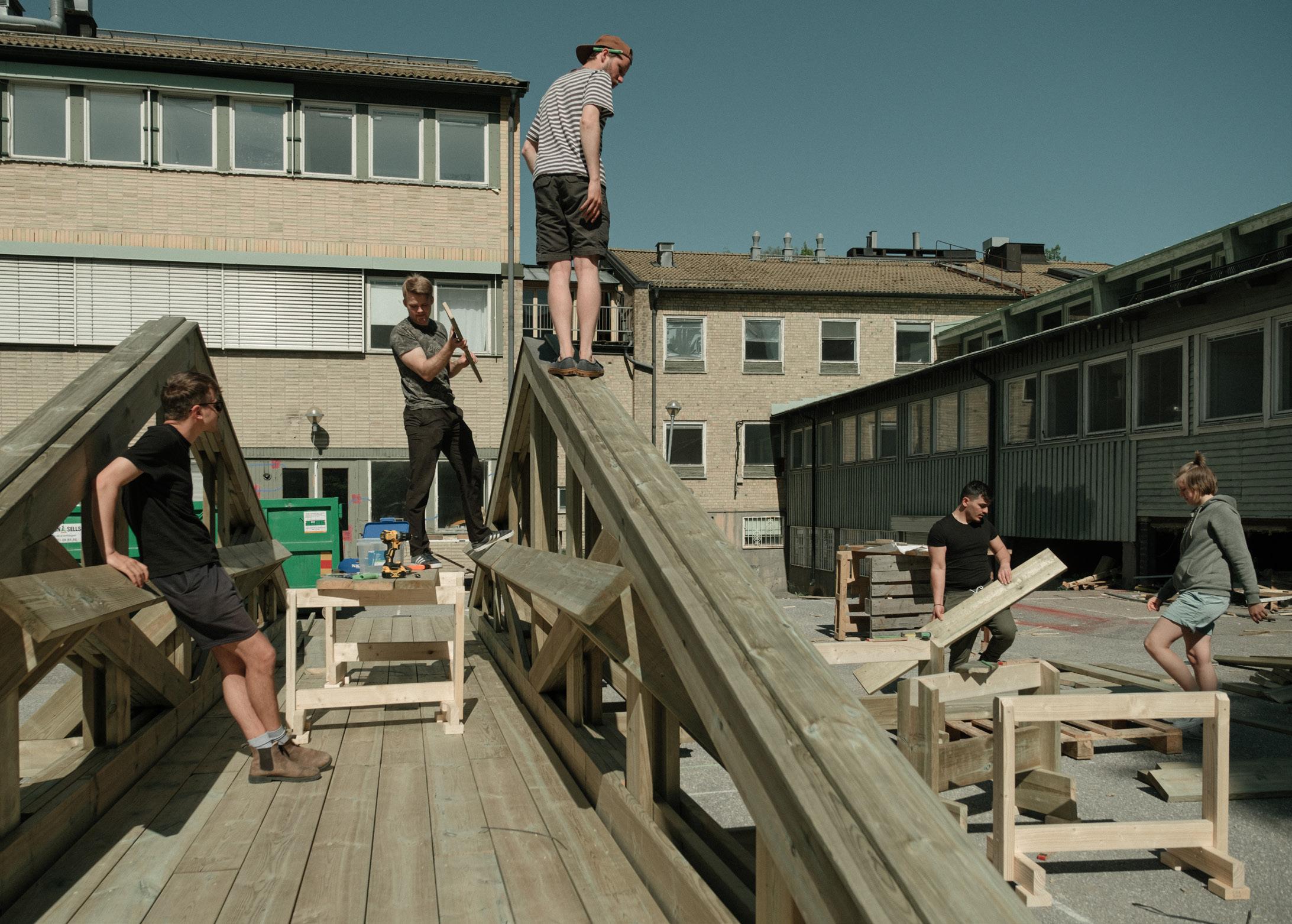
Production
84 Hands 59 82
Peter TomasAllgårdhHermsen
Project 4
Florian Schamper
Marc Lütticken
Engineering
Architecture HTW
Anna Vulovic
Yingnan Chen
Niklas Wulff
Architecture Benjamin Tengzelius
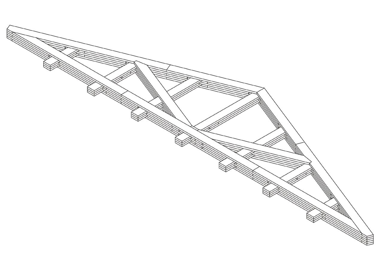
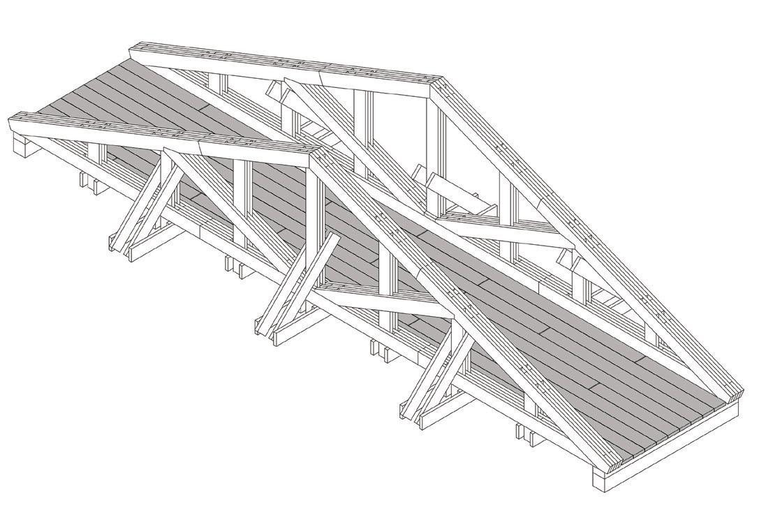
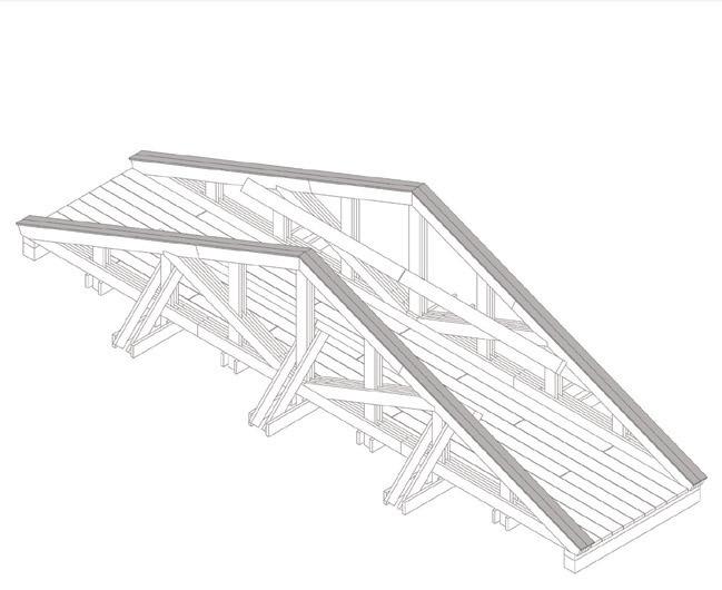
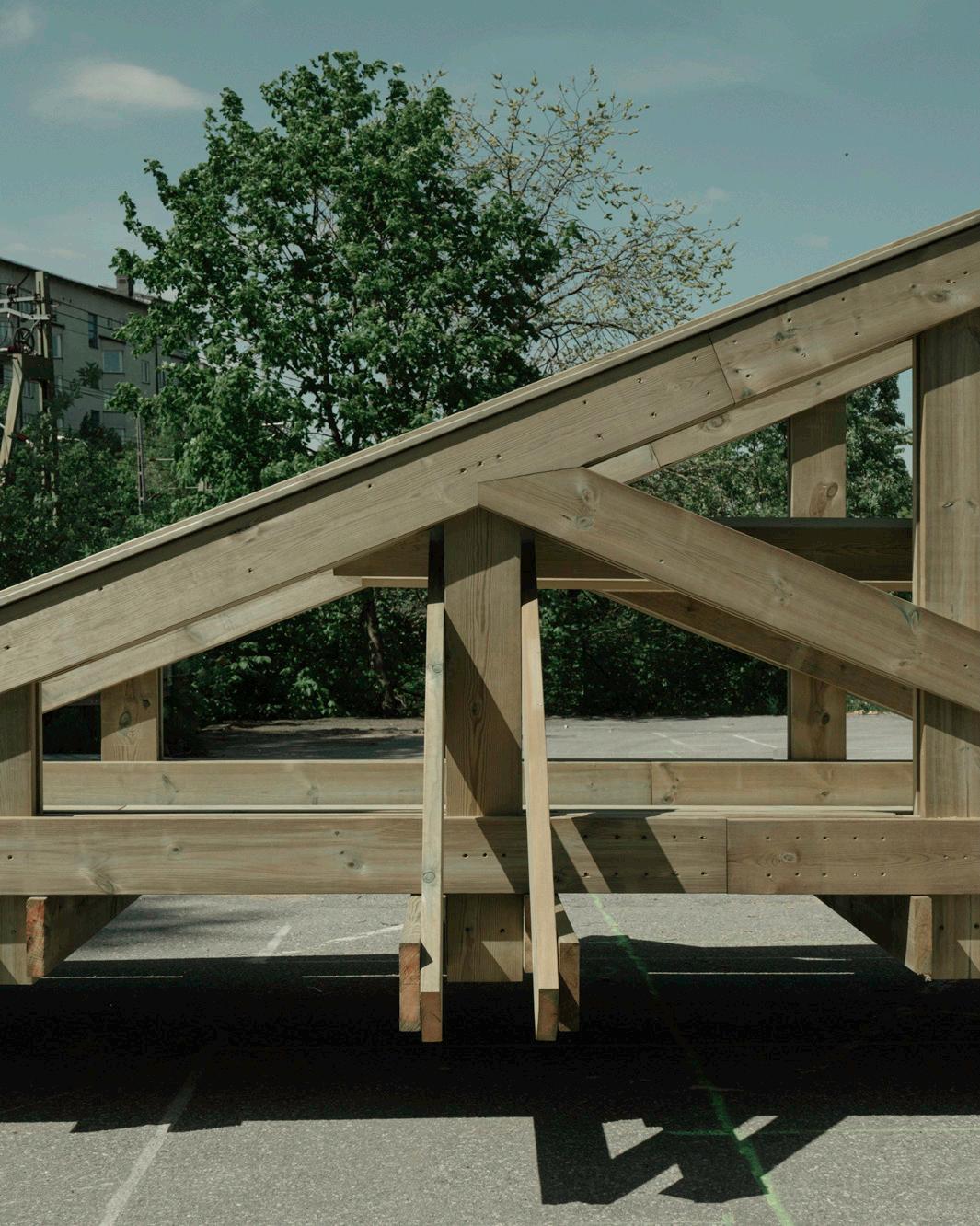
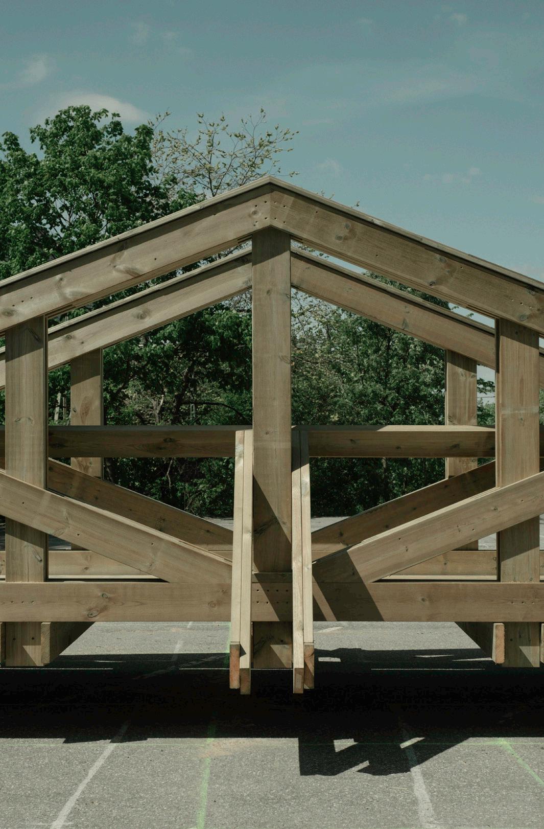
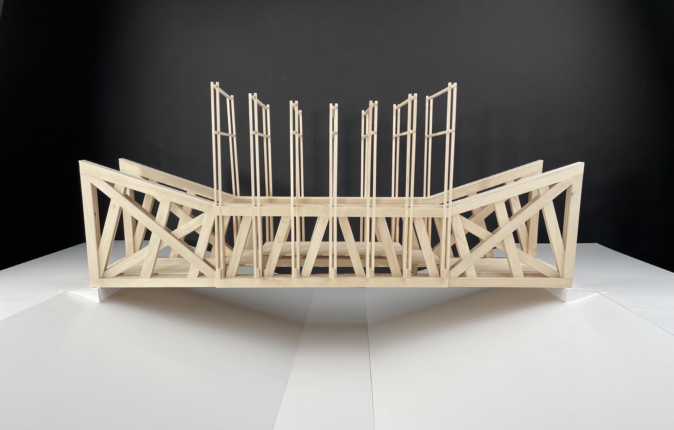
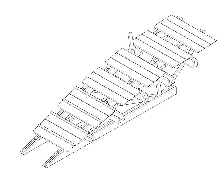
Long Bench Bridge
Long Bench Bridge 61 82
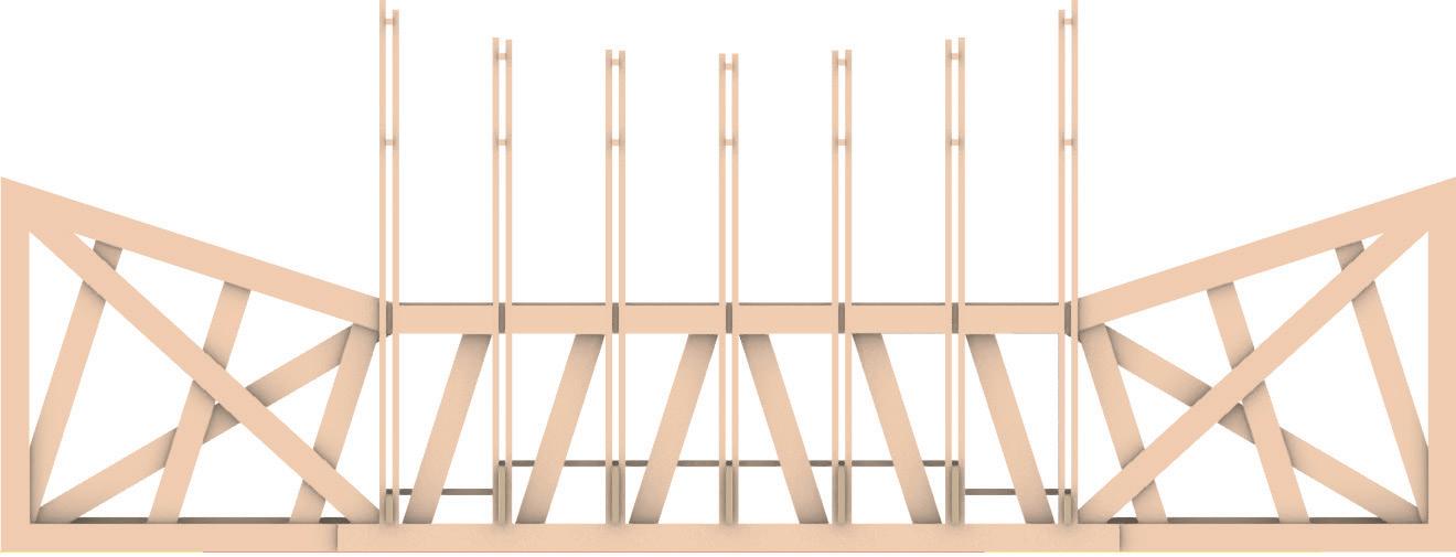
Long Bench Bridge 62 82 1:10 000 Longitudinal Section 1:10 Transversal Section 1:10 400 9045x195500 3615 45x75
Long Bench Bridge 63 82 1486 1200 510 4000 2000 15971917 191715971486 10000 Side View 1:10 4000 510 2430 540 3615 24510601060 Plan 1:10245 445 1712 1545 1671
Long Bench Bridge 64 82
Long Bench Bridge 65 82
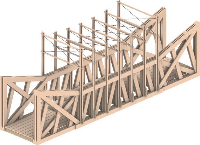
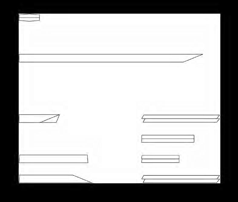
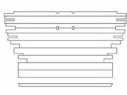
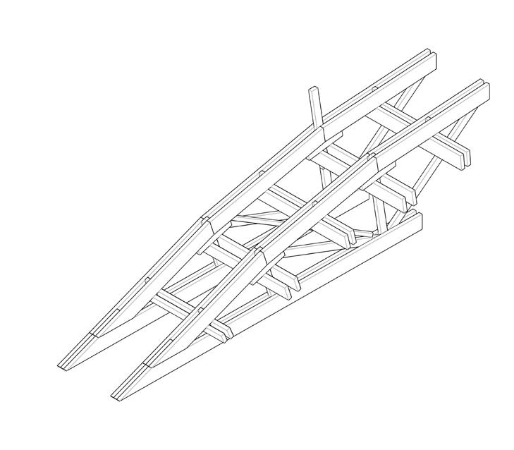
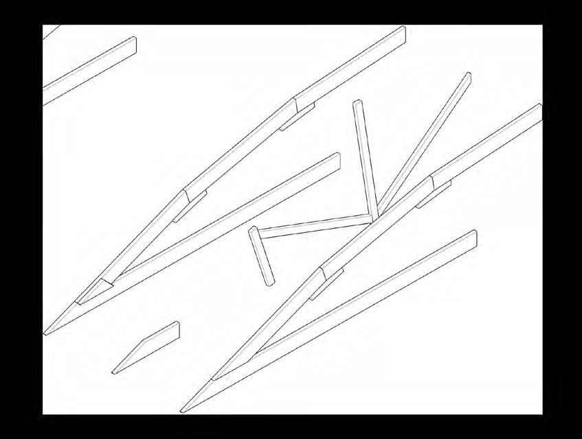
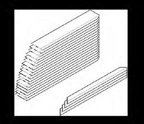
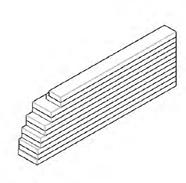
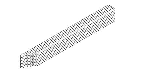
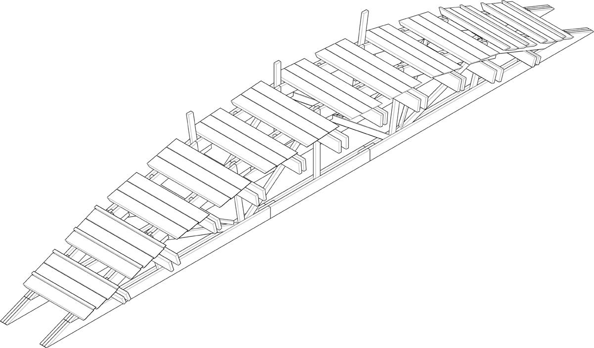
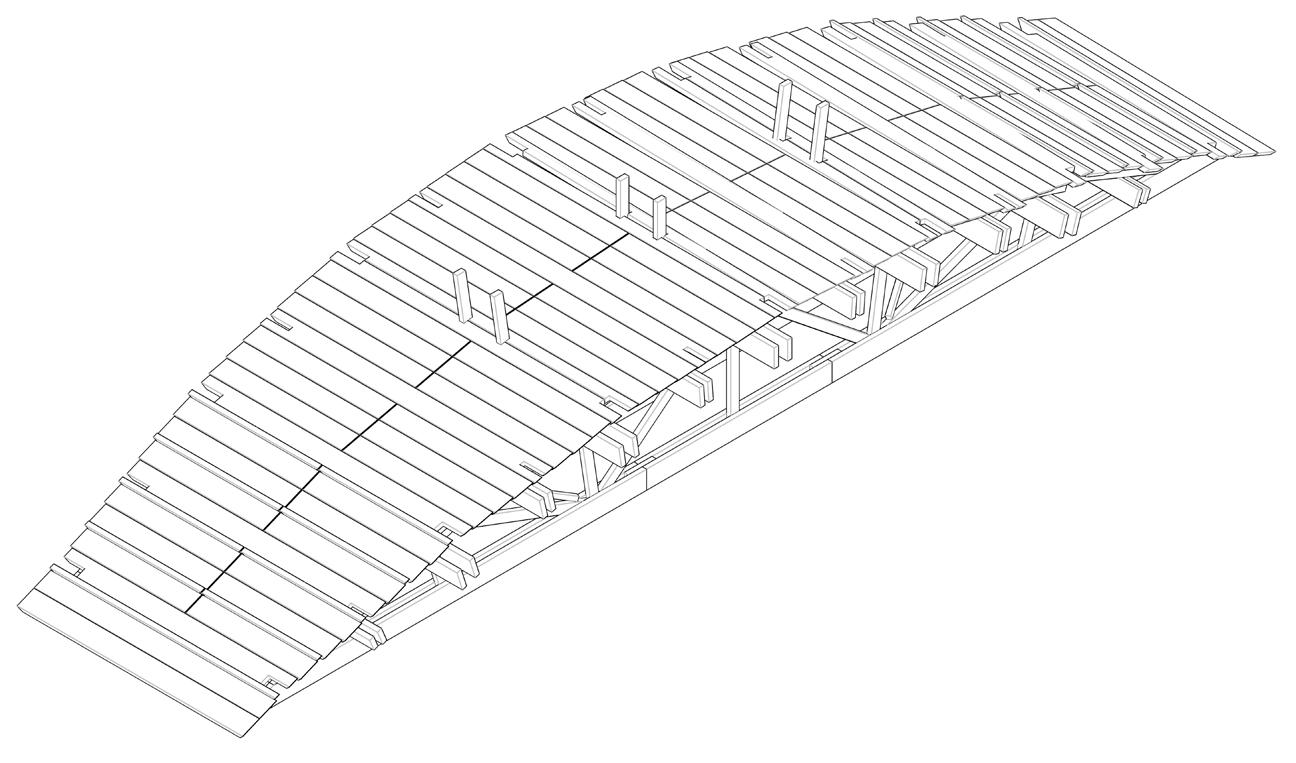
Long Bench Bridge 66 82 8 Half Arches 8 Bracing Crosses & 44 Tranverse Beams 110 Deck Panels 4 Connecting Trusses 32 x 16 x 8 x 4 x 4 x 8 x16 x 16 x 2 x 2 x 2 x 2 x 2 x 8 x 8 x 4 x 4 x 2 x 24xx 16 x16 Total:x 61.5m x (45mm*195mm) + 9.36m x (45mm*45mm) 500180 500300 180180 180 180180 180 195 195 195195195 4495 16309901665 1686 19081908920128217271790 14431452 130414151370390 1205 Web Members Top Total:Chords230m x (45mm*195mm) Total: 174m x (45mm*195mm) Total: 28.8m x (45mm*195mm) 115m x (45mm*195mm) 59m x (45mm*195mm) Bracing Crosses Tranverse Beams (At ends & mid) Tranverse Beams (Others) Tranverse Beam Connectors (each two have one) Lower In-betweenChordsmembers4x4x 8 x 4524 x 4 x 4 x 4 x 4 x 2 x + 4 x 195195 150150 195195195 195 2000195180 1395 1785 180 180 110150 1569 2432243224322428265128322967307530753130315014001305 12361267129213431368138814301447146314921505150515401547155415641567


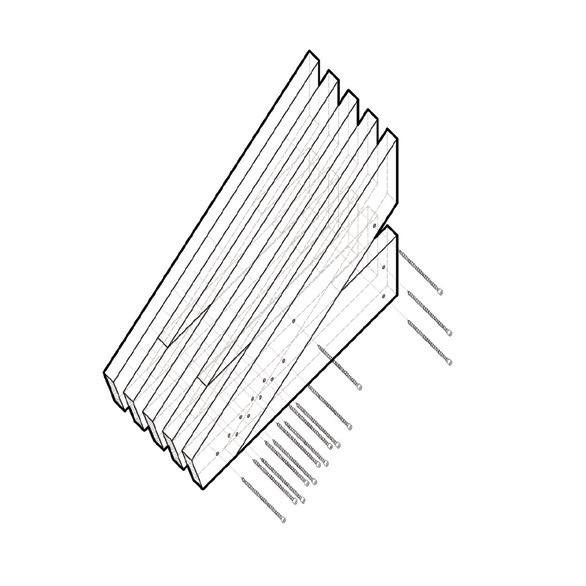
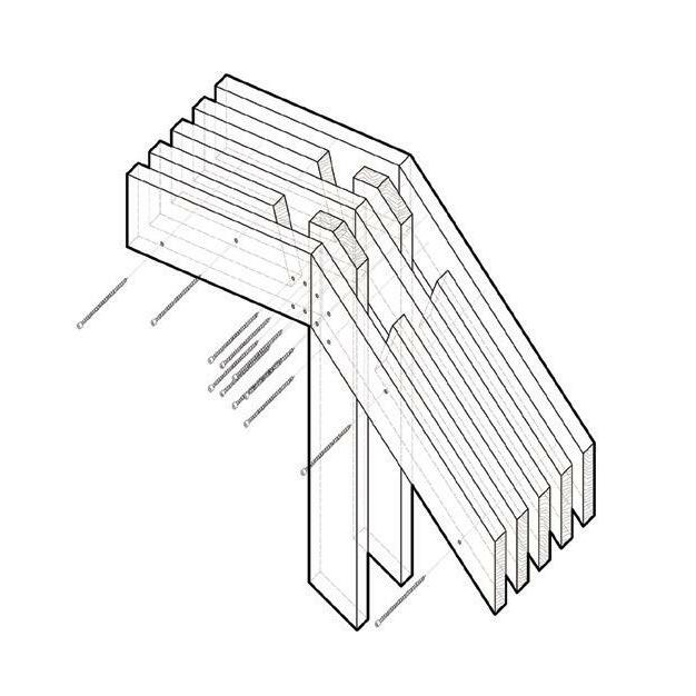
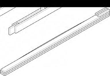
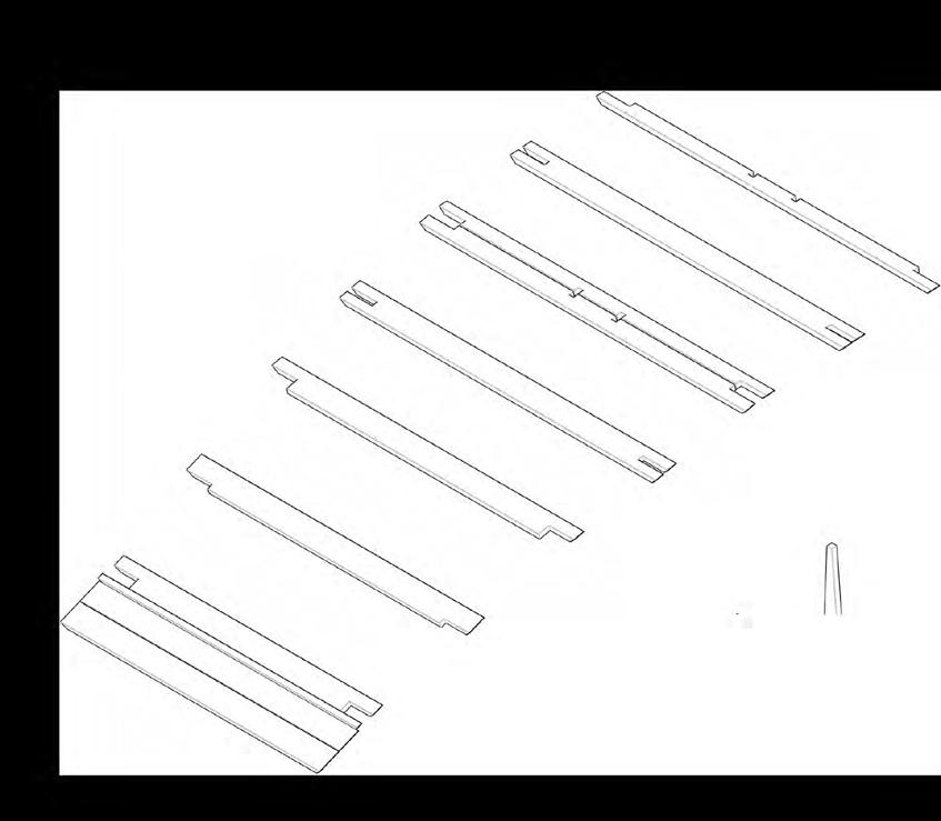
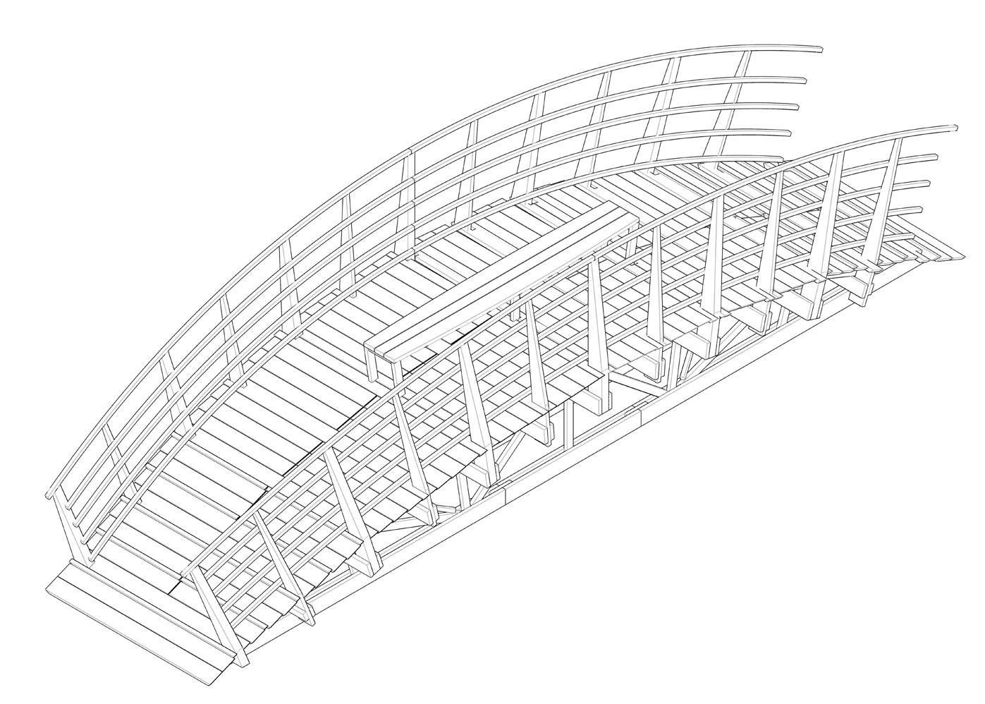
Long Bench Bridge 67 82 On-Site Assembly On-Site Assembly 2 (Handrails + Bench) 4 x 2 x 1 x + 2 x 2 x 2 x + Bench (45mm thick) 3615 10 x4 Railpostsx (100mm1560thick) 1860 200 200 12Railpostsx (45mm1860thick)195 130195 135 335 Total: 10.845m x (45mm*195mm) + 24.84m x (100mm*200mm) + 111.58m x (45mm*45mm) Other Material Use Roofing paper 50m or 4 rolls of 15m Metal FastenersVGZC49*200 8 (on raillings) + 264 (on trusses) = 6*120272 150 (on railings) + 360 (on trusses) = 510 6*120 or nails 344 (on railings) Deck Screws or 6*120 488 (on decks) Ankarskruv 4.8x Steelplate3204040 Bridge total Wood Use 505m x (45mm*195mm) + 25m x (100mm*200mm) + 122m x (45mm*45mm) 8 Handrailsx 2.656m2.714m2.975m2.830m2.773m

Long Bench Bridge 68 82

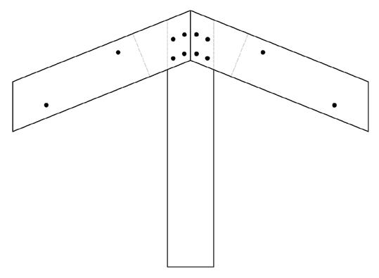
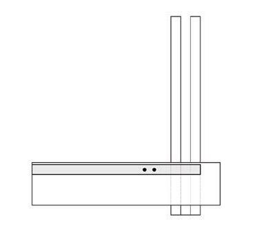
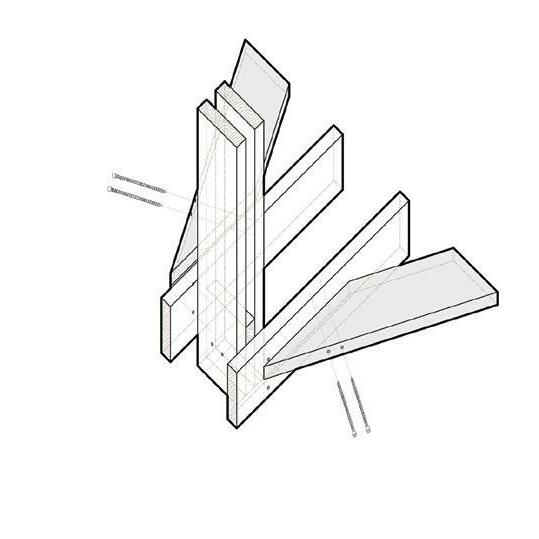
Long Bench Bridge 69 82 50 cm 4.8X40Ankarskruv Screw C4 6X20 VGZ 9x200C4 SideSideSide Top 50 cm From 90X4590X45X50195X45Roofingpaper2mm195X45top:decksteelplateArchArchjointverticalmember 4.8X40Ankarskruv Screw C4 6X20 VGZ 9x200C4
Long Bench Bridge 70 82 50 cm 4.8X40Ankarskruv Screw C4 6X20 VGZ 9x200C4 50 cm 4.8X40Ankarskruv Screw C4 6X20 VGZ 9x200C4
Long Bench Bridge 71 82 50 cm 4.8X40Ankarskruv Screw C4 6X20 VGZ 9x200C4 The joints in the handrail are made over 100X200 posts
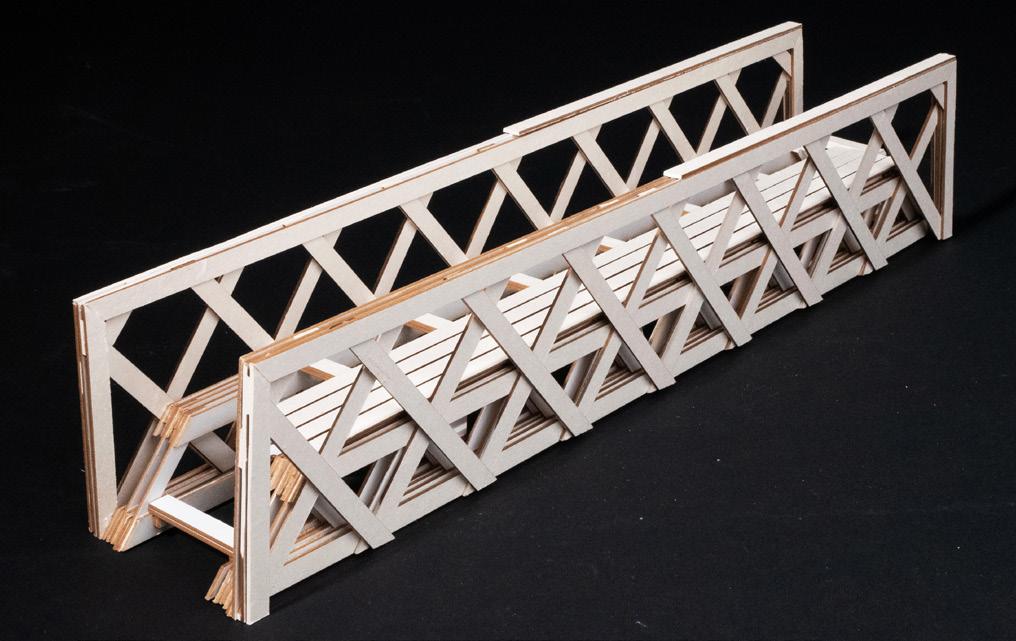
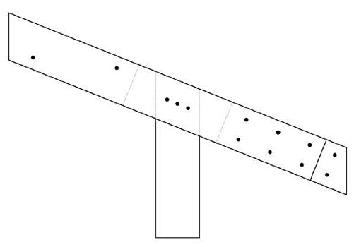
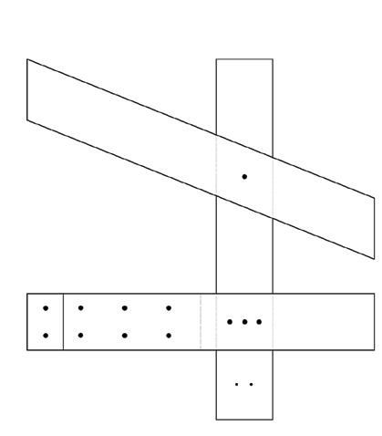
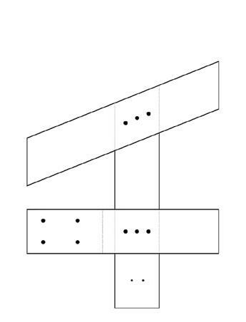
Project 5 Architecture Philip Reimers Zoe AndreasDuranPetersson Engineering Niklas CorentinSandraÅStrömSuursöötLeGall Bridge of Truss.T
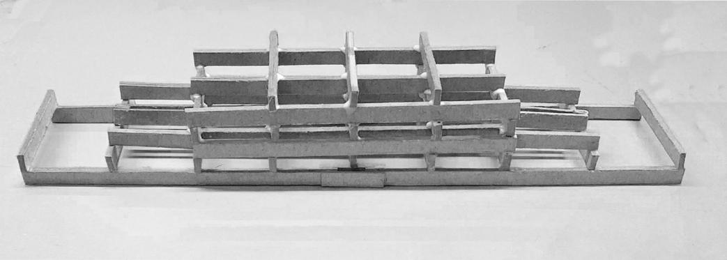
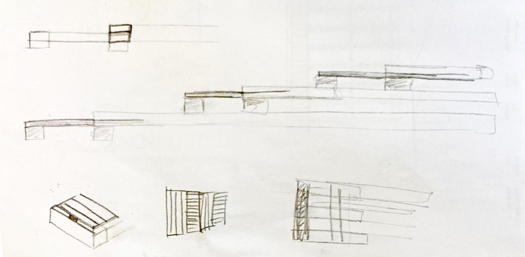
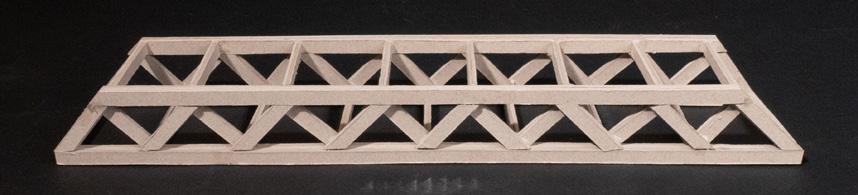
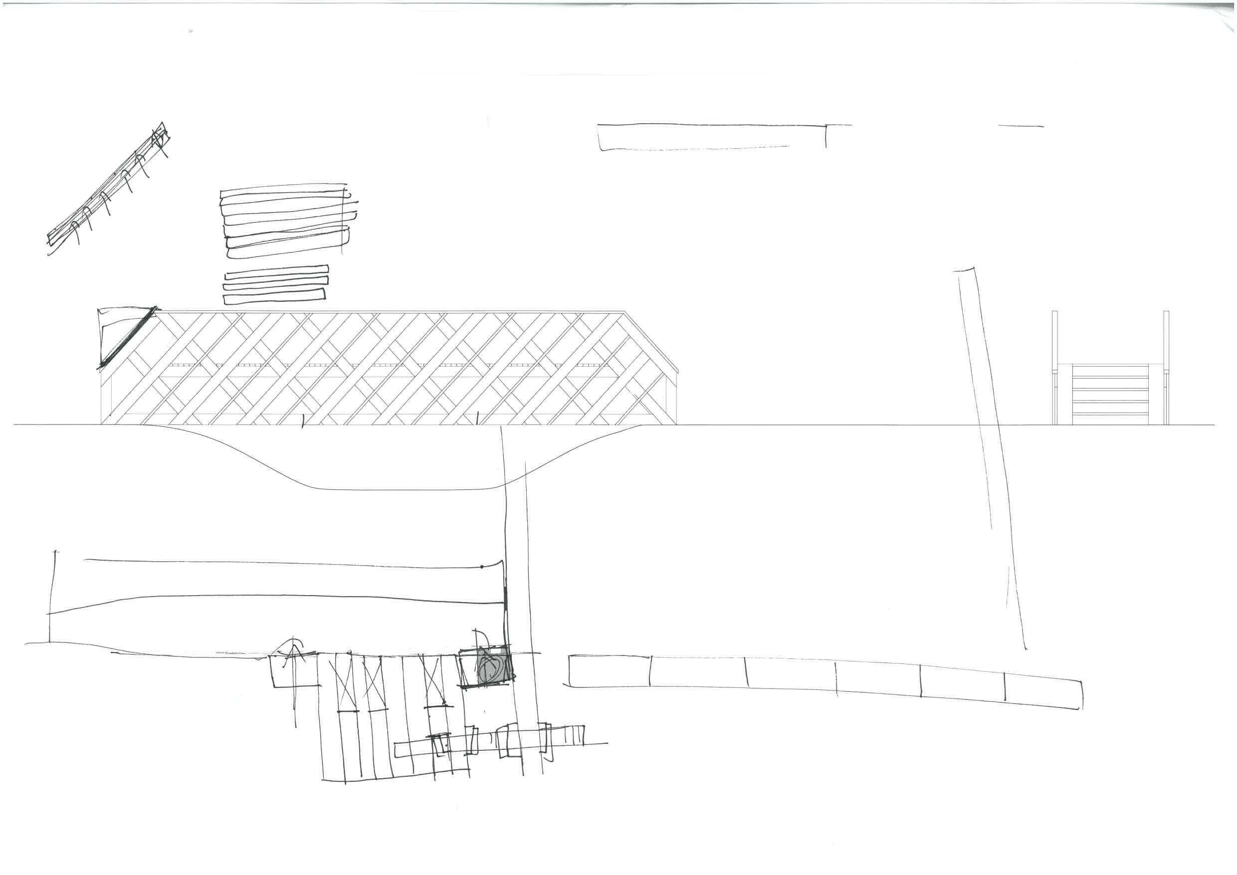
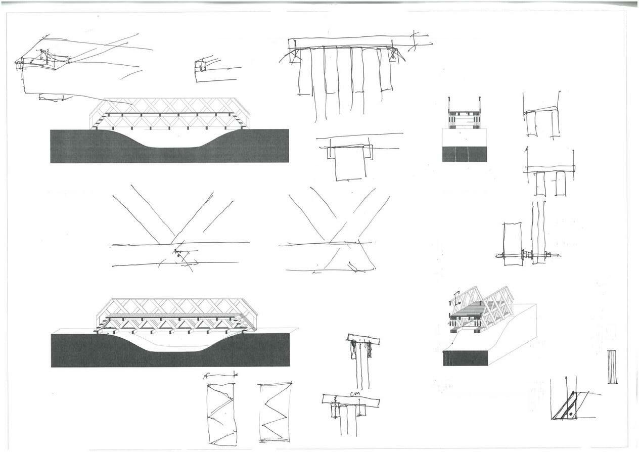
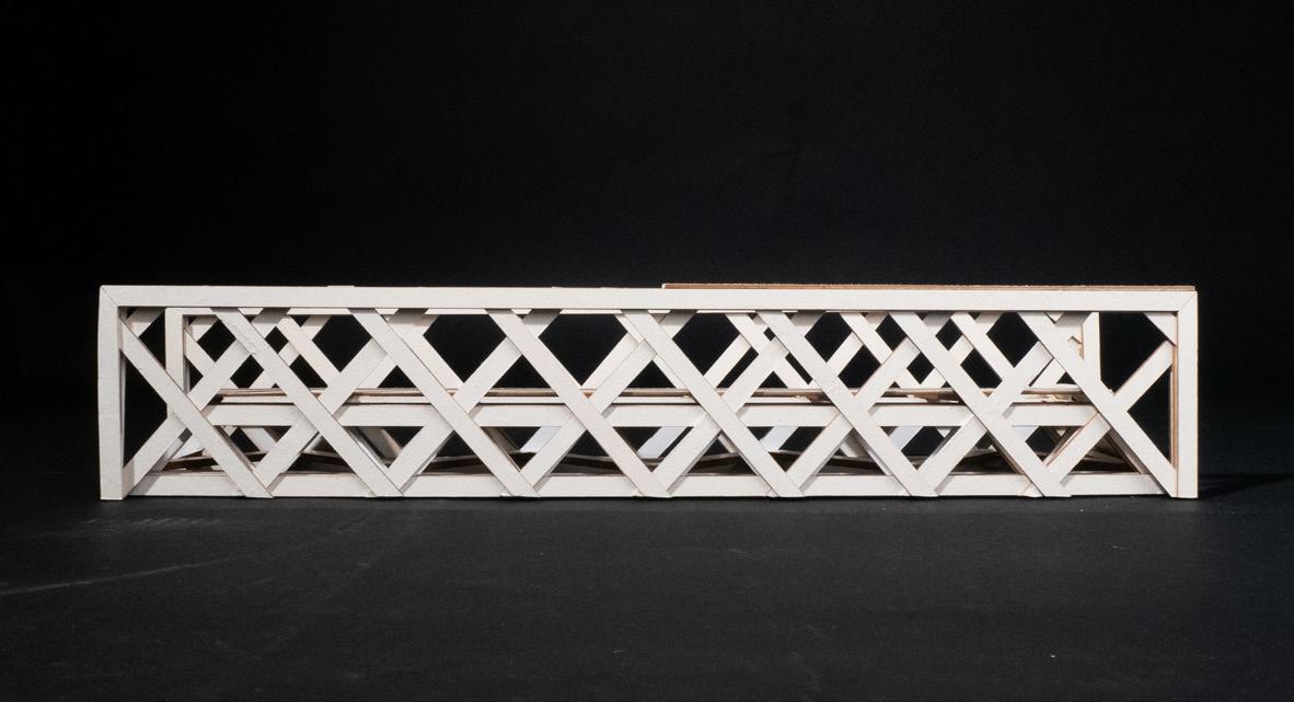
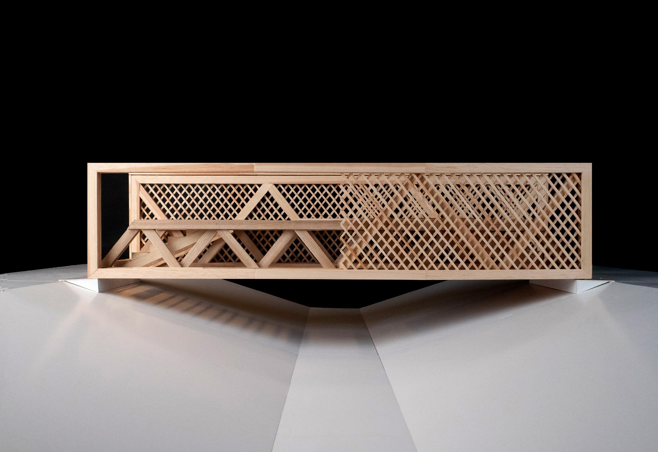
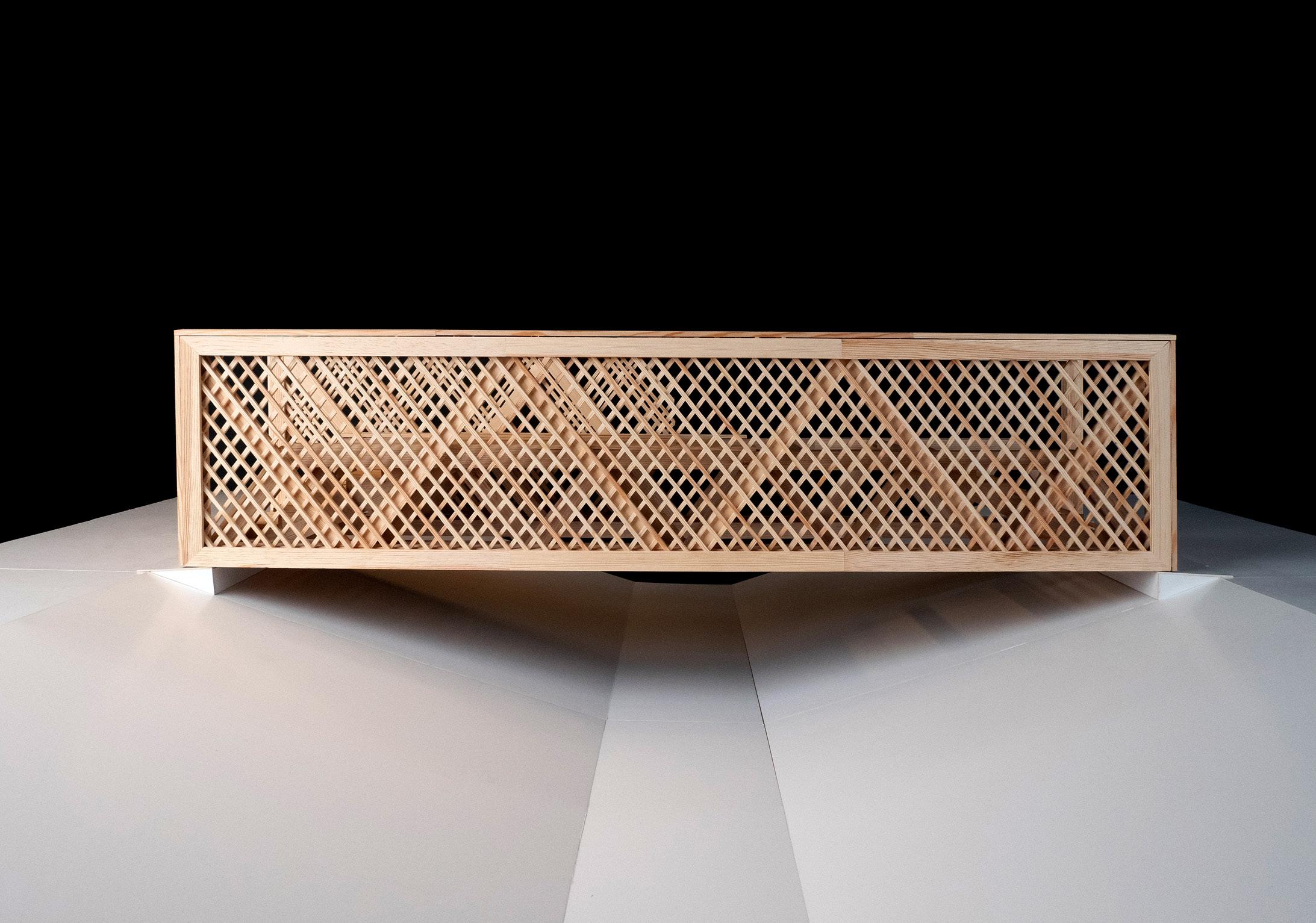
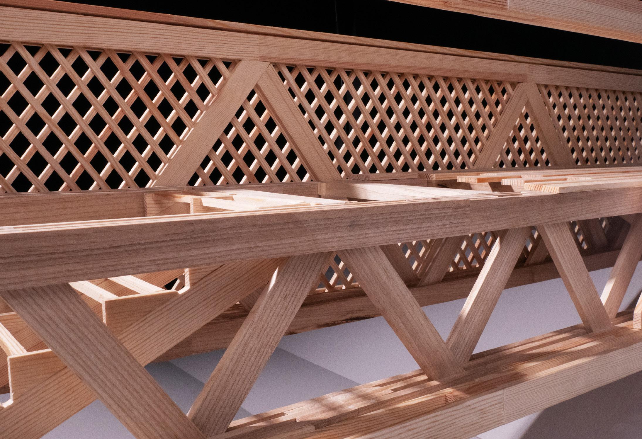
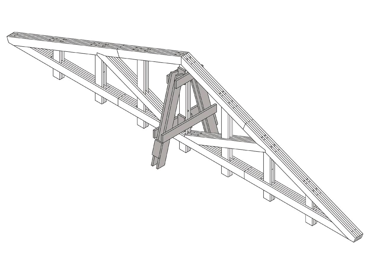
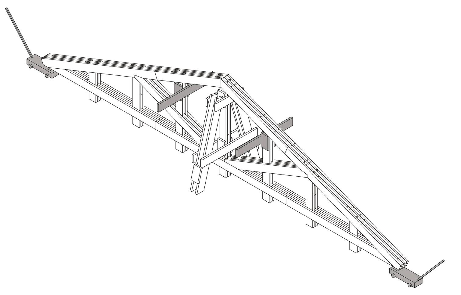
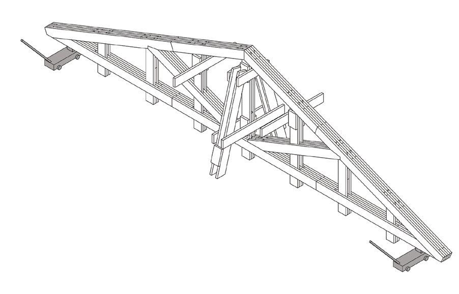
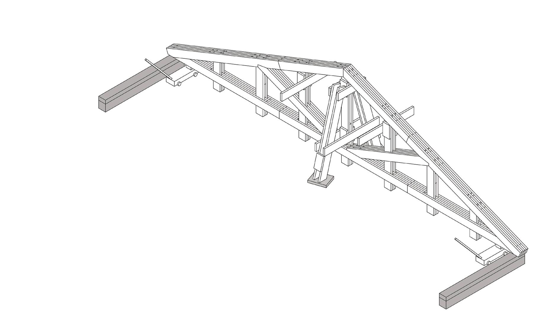
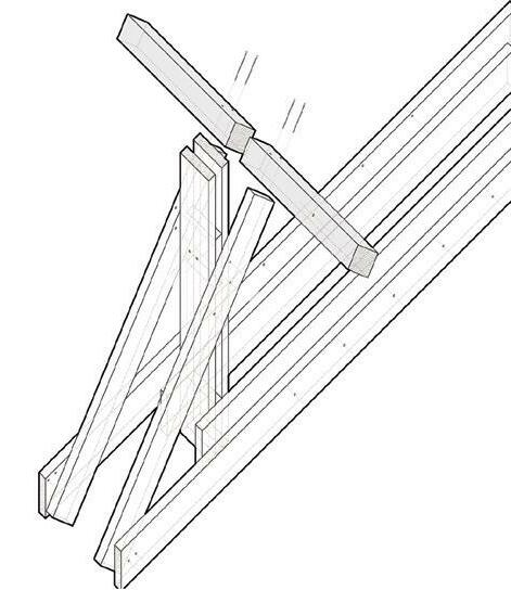
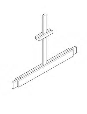
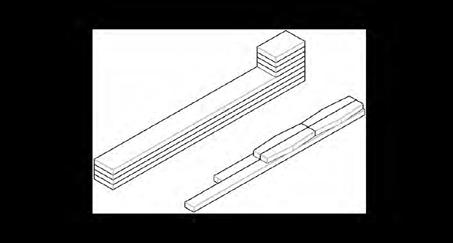
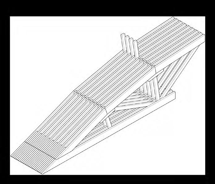
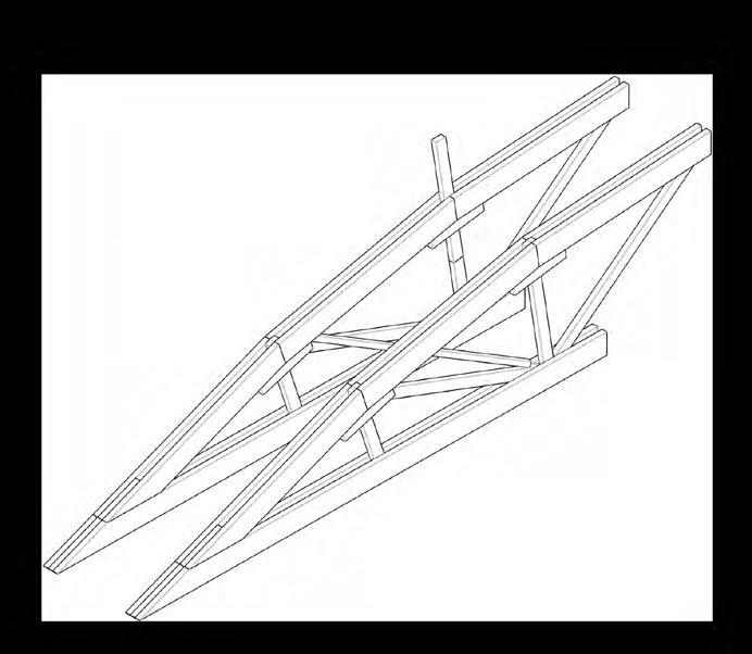
HildingTruss
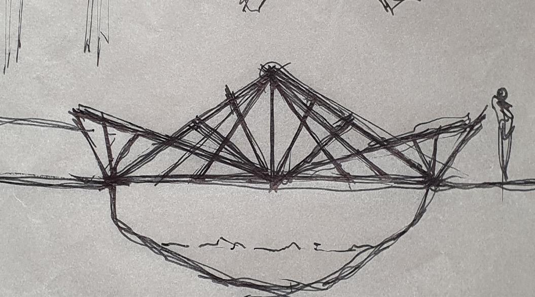
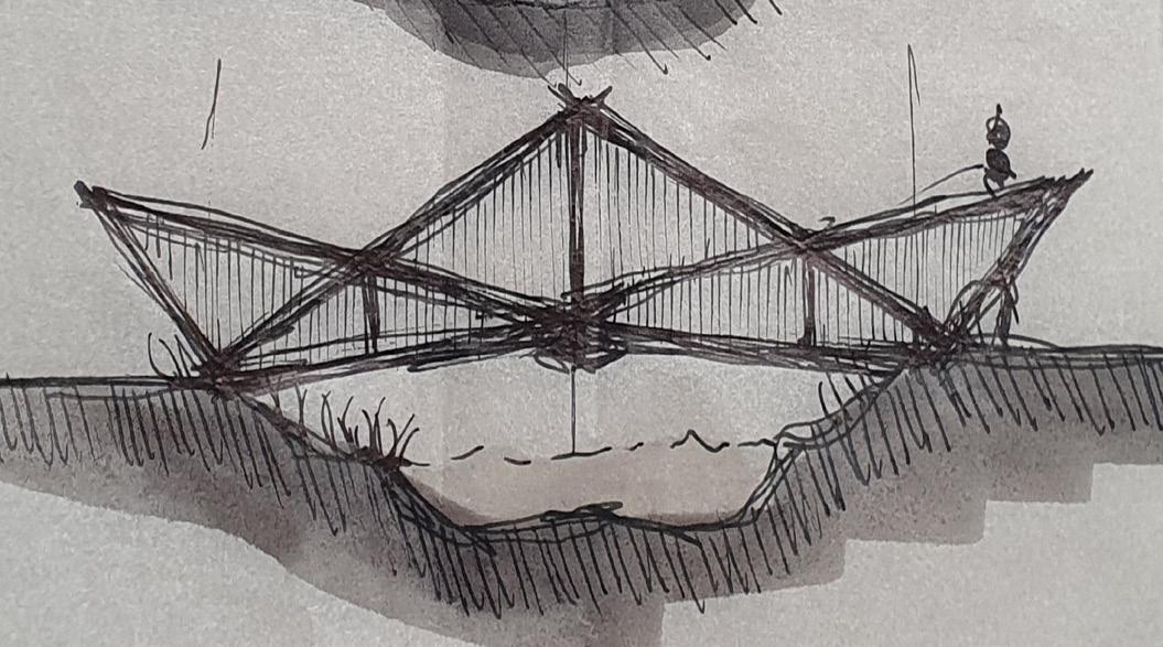
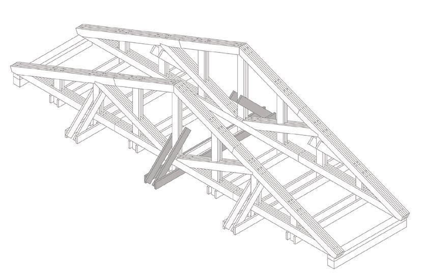
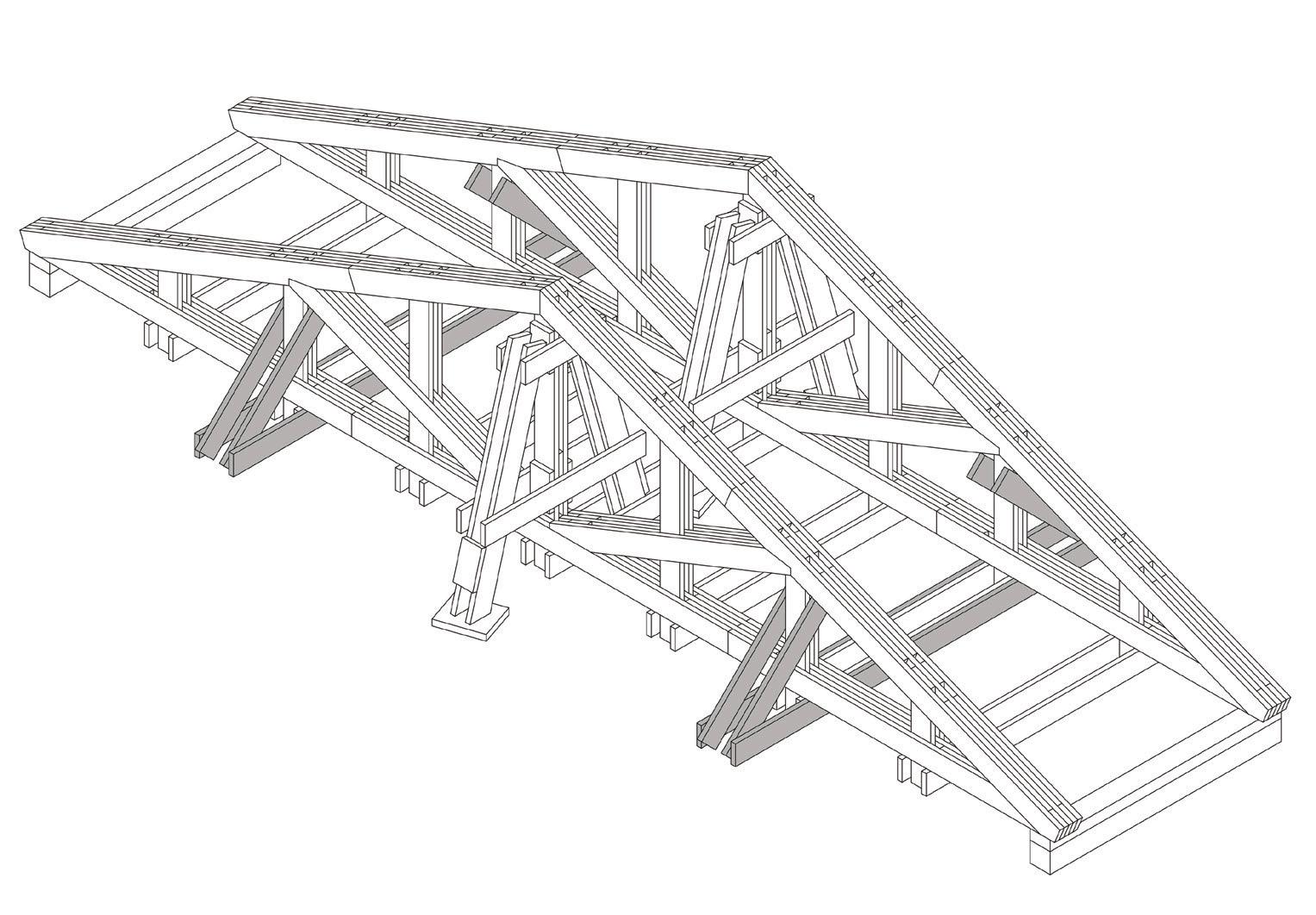
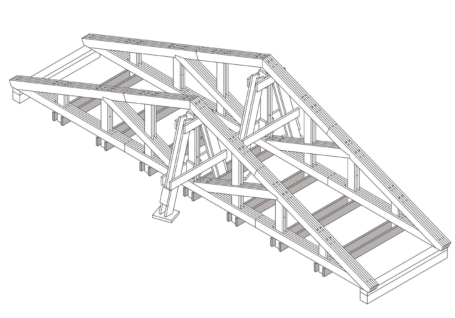
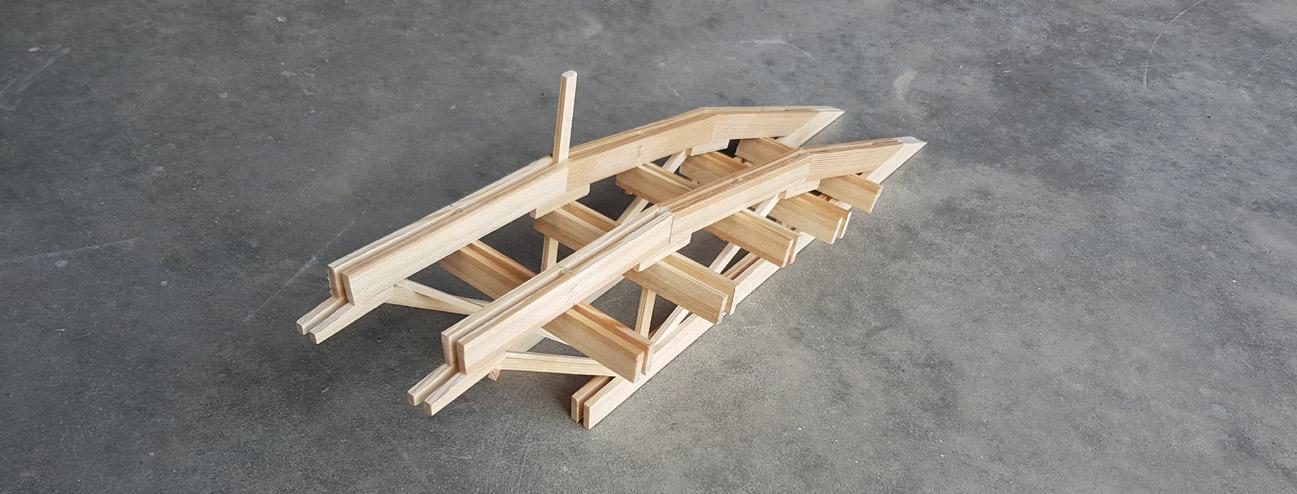
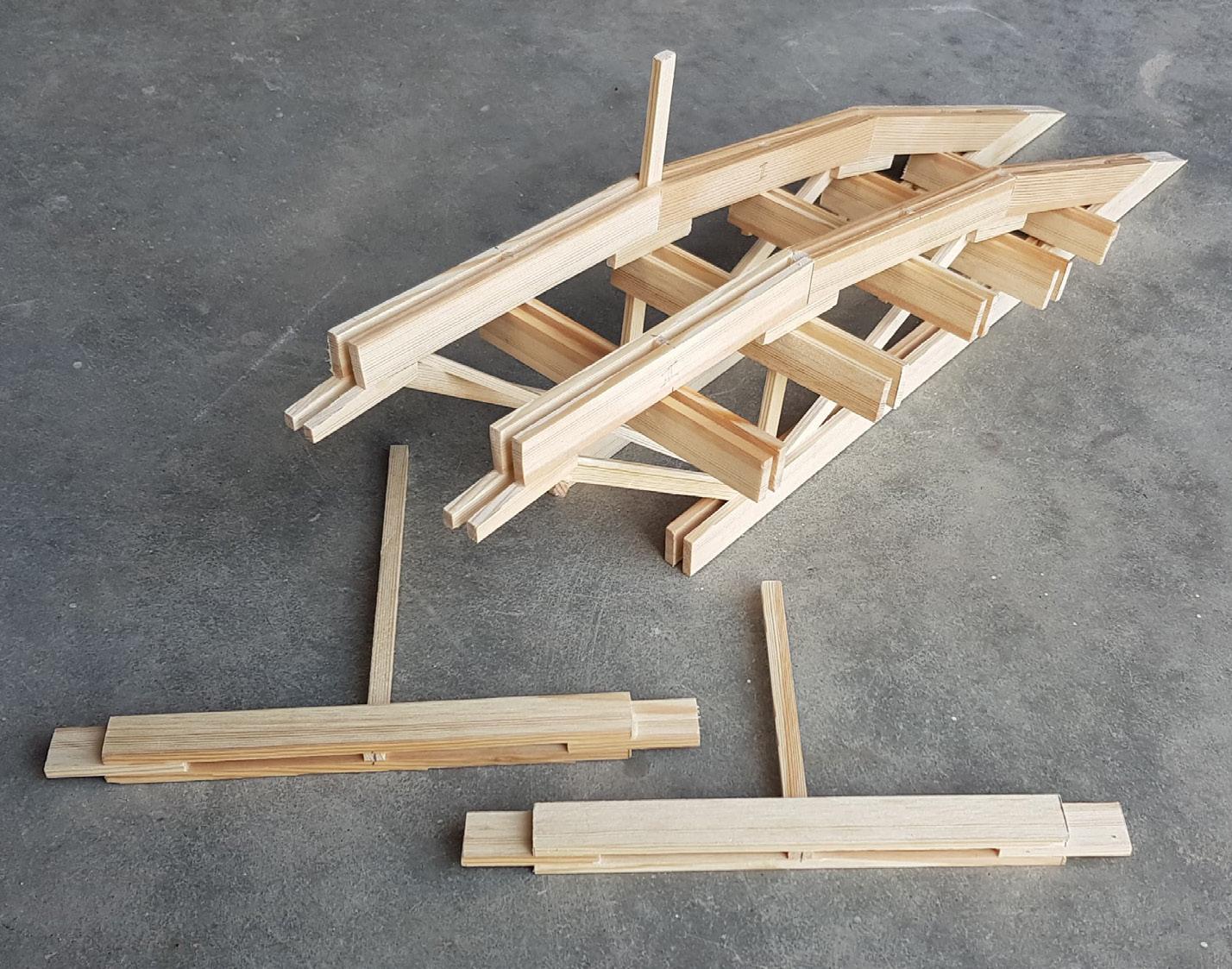
Two parallel constructions
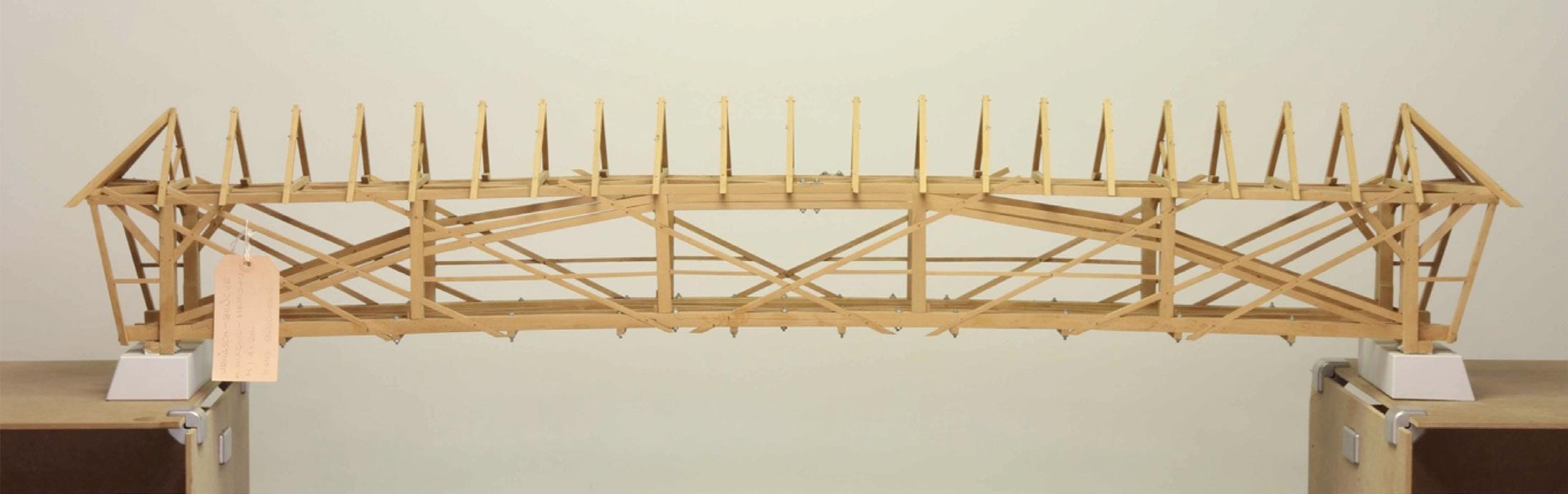
Through out the project we worked on two different construction principles with their own unique style and shape. The idea of using Hilding Brosenius construction came from the building Snickarhallen which used this type of construction, where also the winning proposal later would be built in. Because of the labor intensive work and possible shorter lifespan of the bridge we decided to go further with the truss construction, taking with us the Hilding Brosenius as an interesting construction for further exploration in the future.
Bridge of Truss.T 73 82
Brosenius

Bridge of Truss.T 74 82
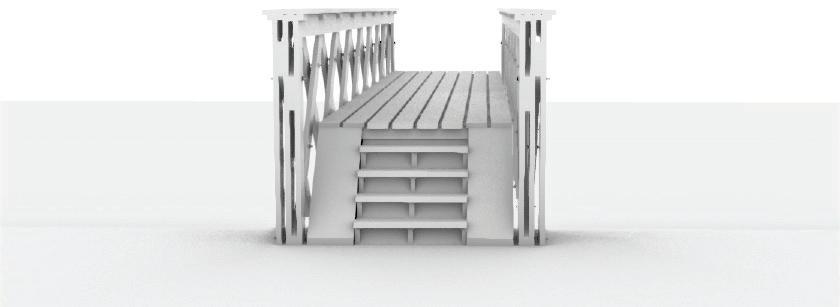
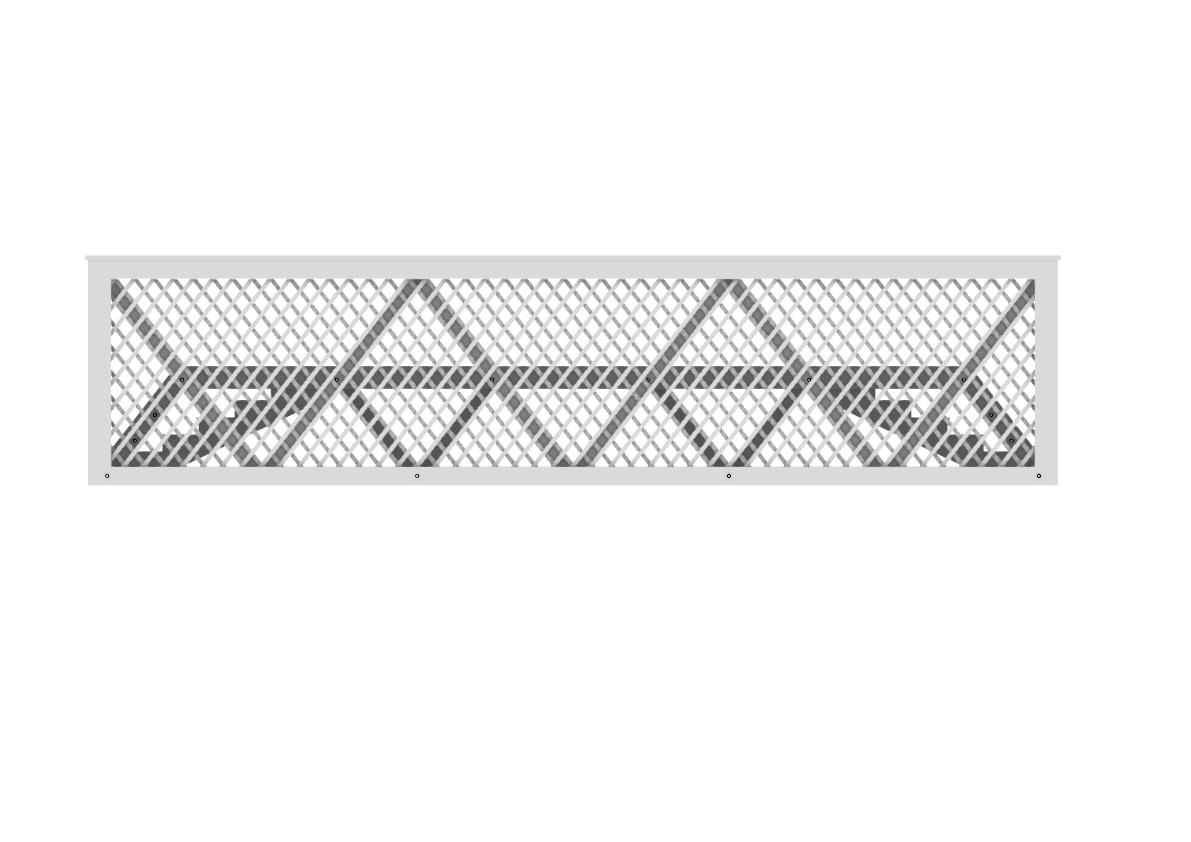
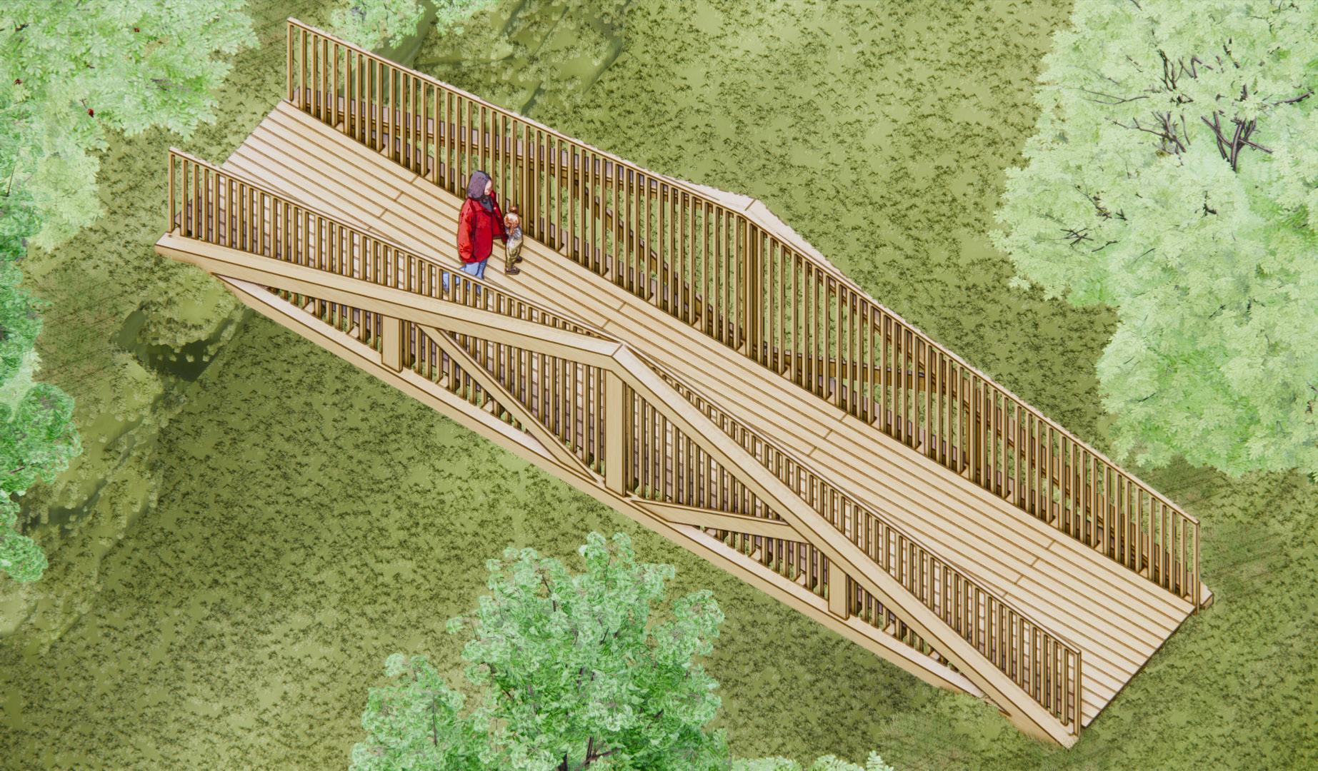
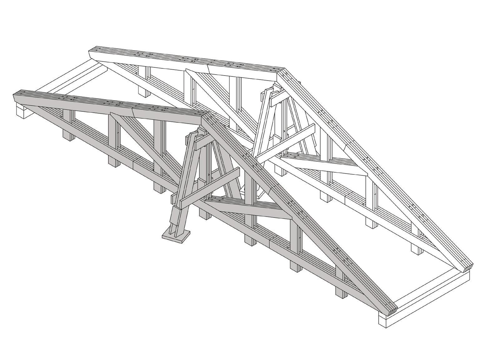
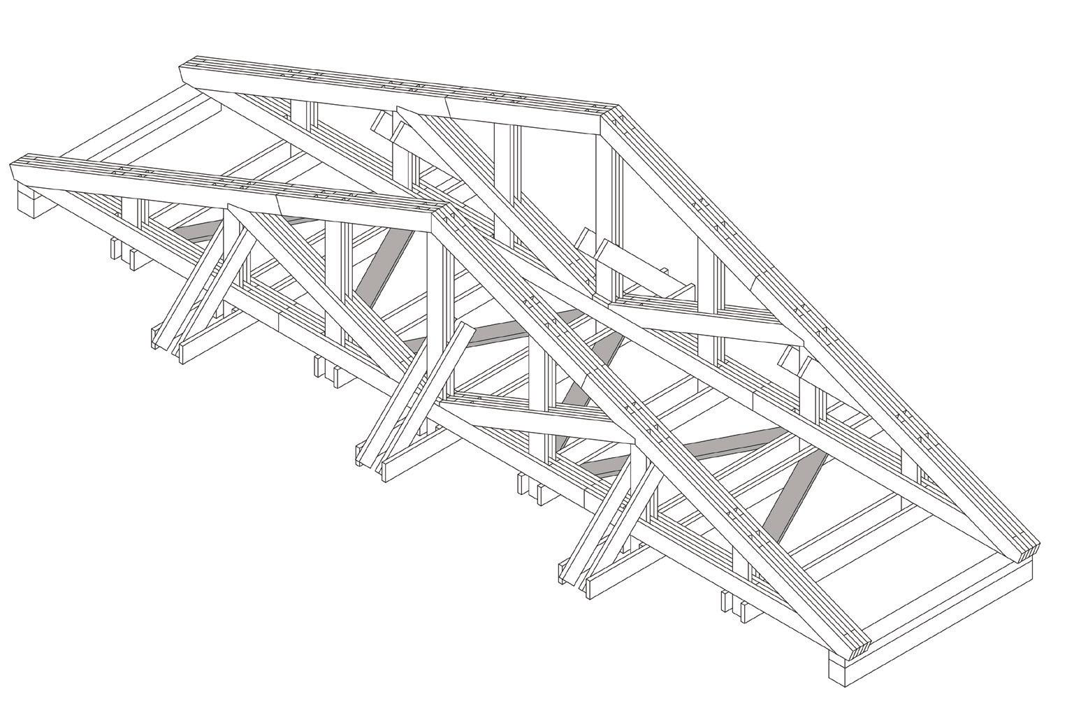
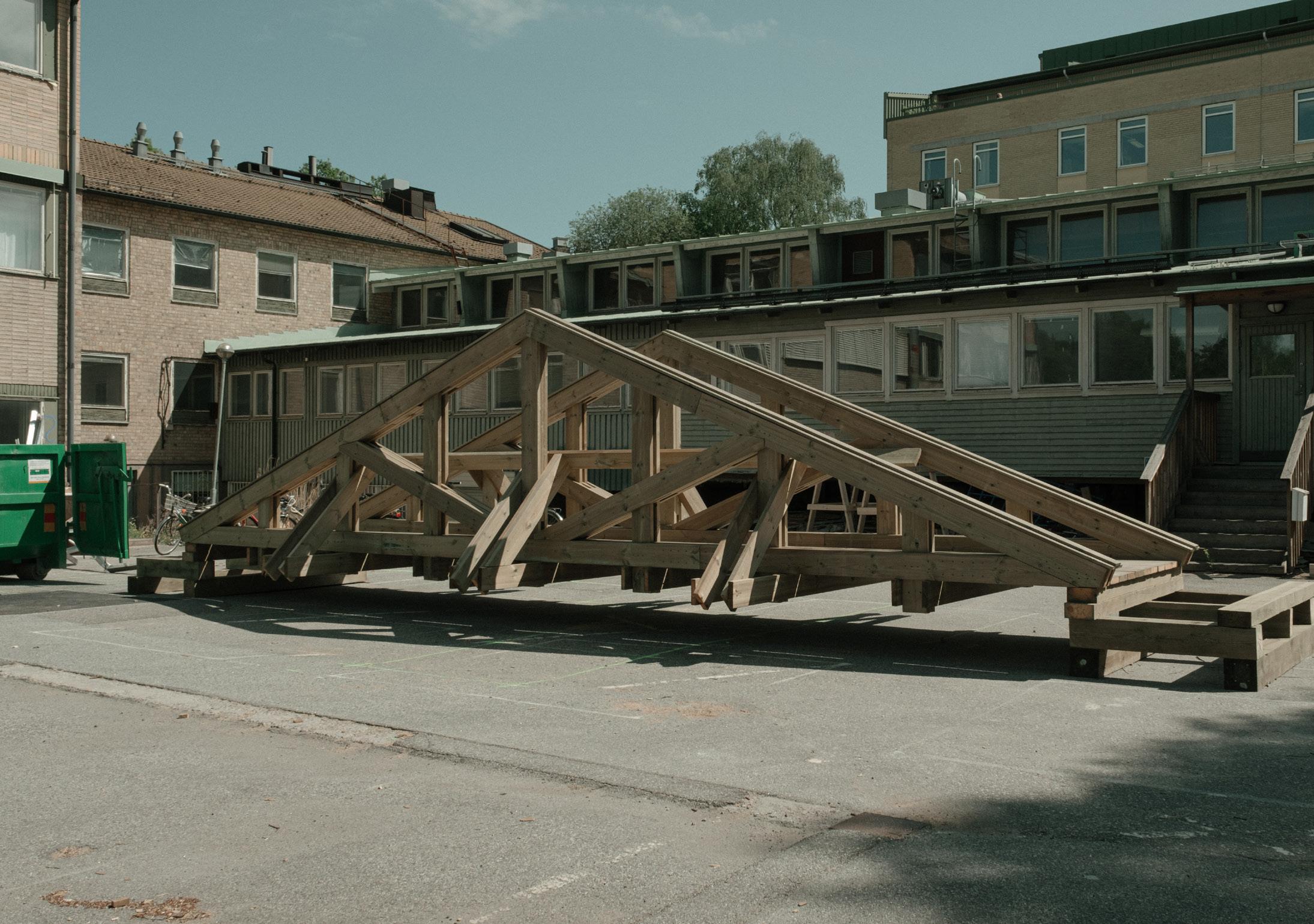
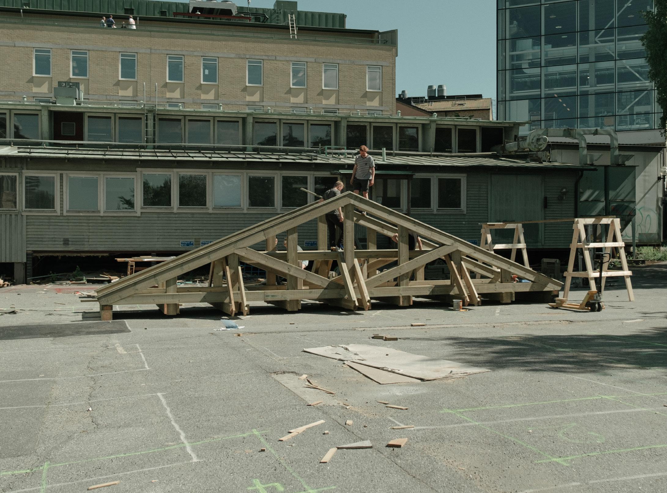
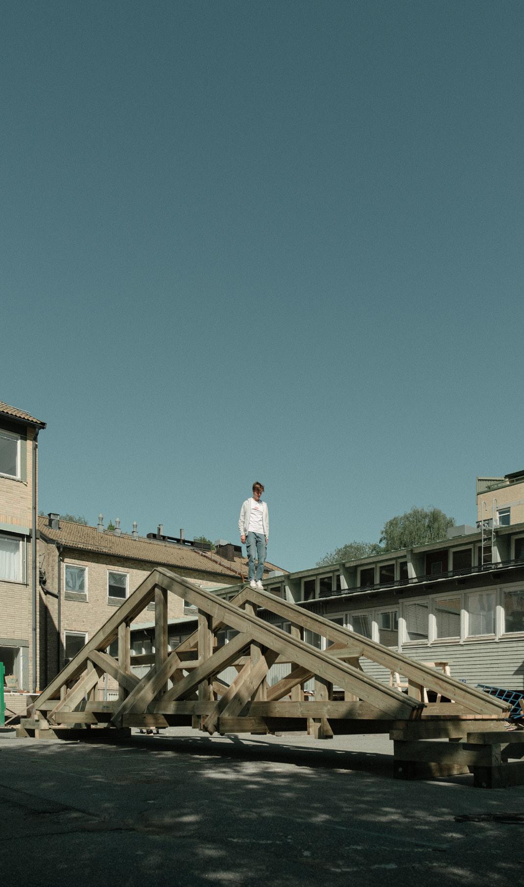
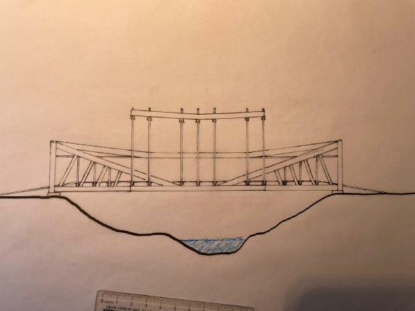
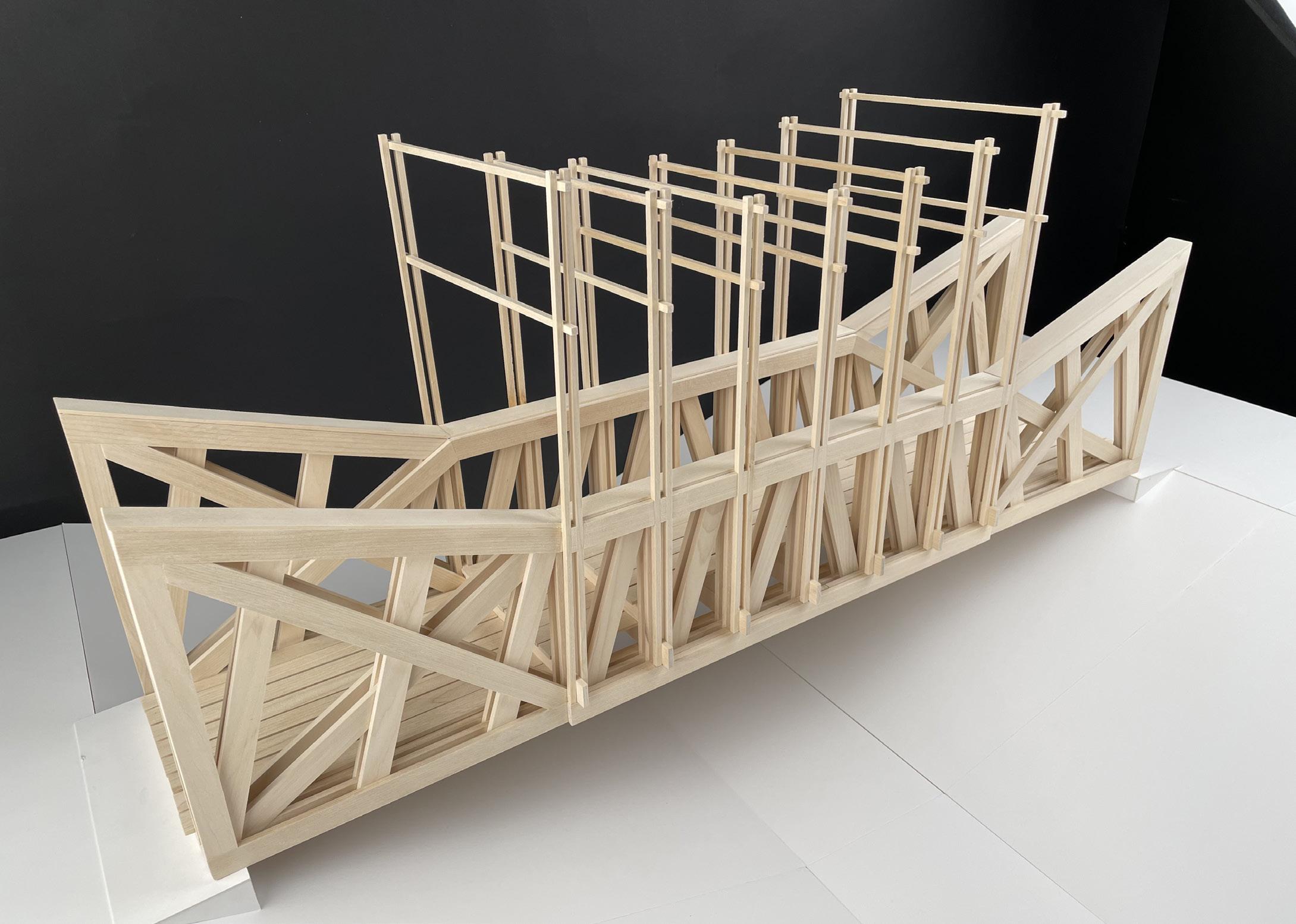
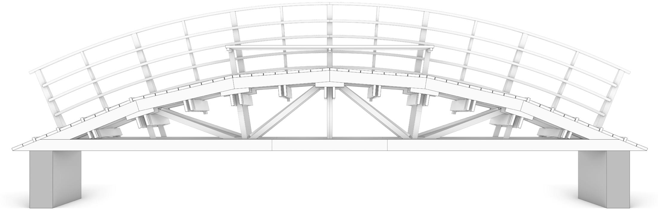
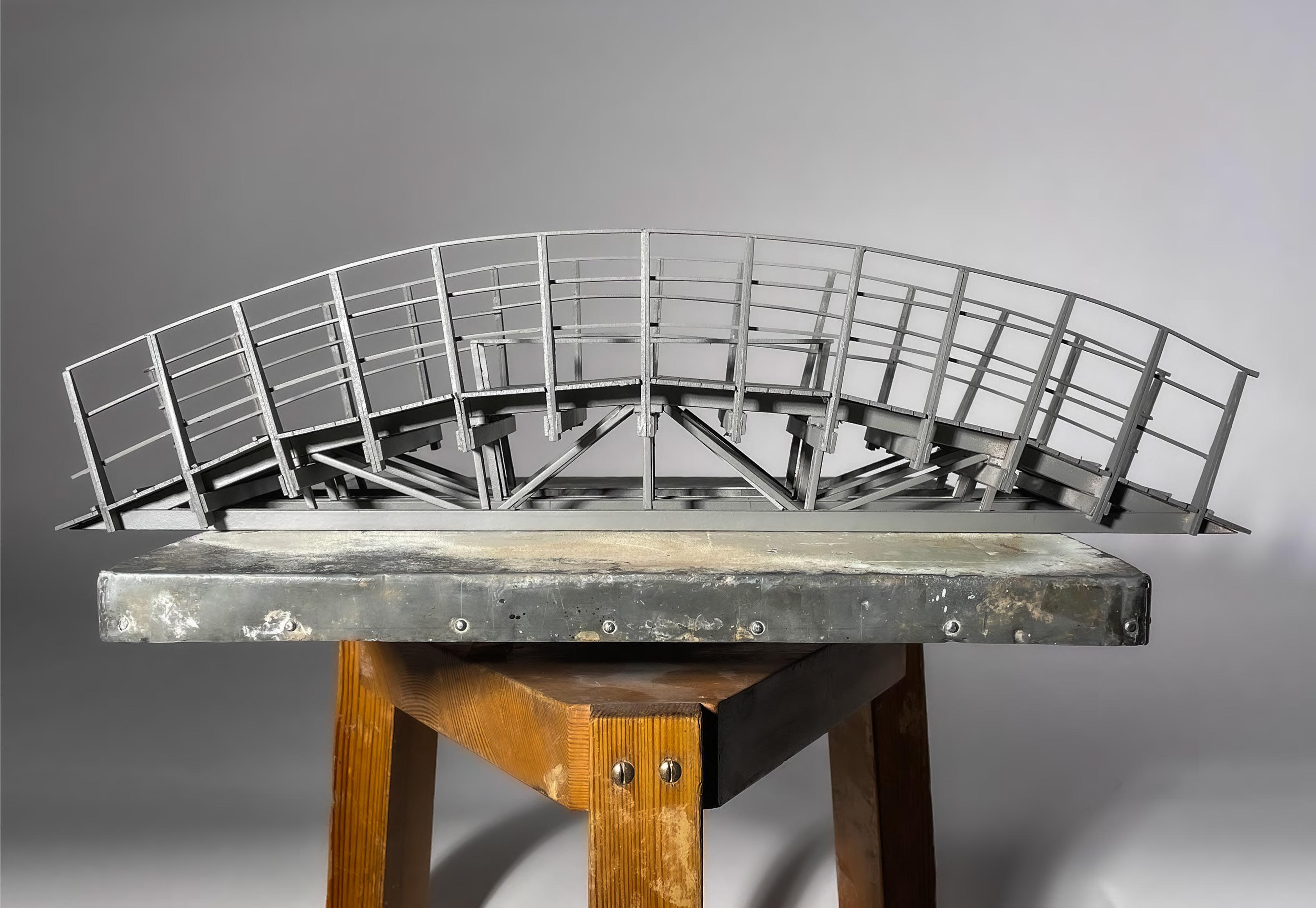
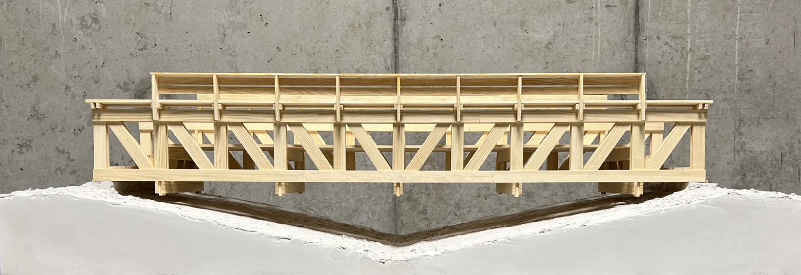
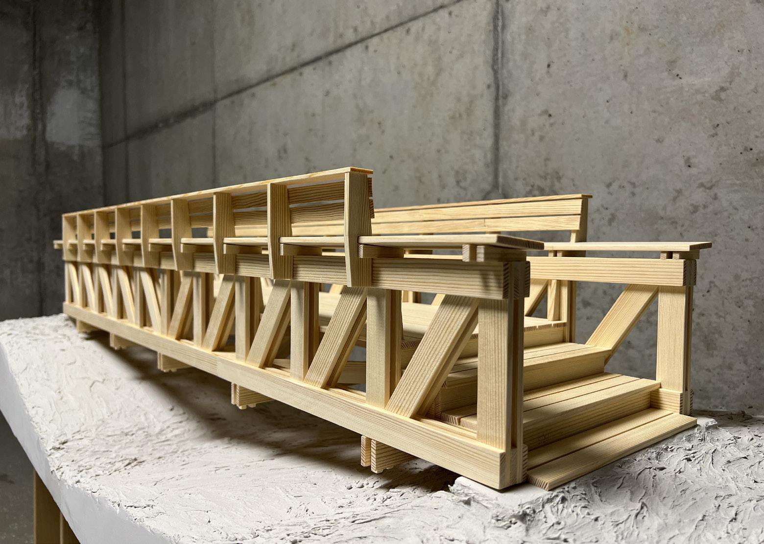
“We designed the bridge with it’s contextual enviroment in mind and by elevating the walkway a few decimeters it allowed us to use the upper chord of the bridge as an seating area, making it a place where you could sit down and enjoy the nature surrounding it...”
Final
design
Bridge of Truss.T 75 82 east elevation 1:20 south elevation 1:20
Bridge of Truss.T 76 82 plan view 1:10 sections and measurements 1:20 (all measurements in mm)

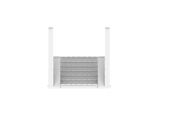
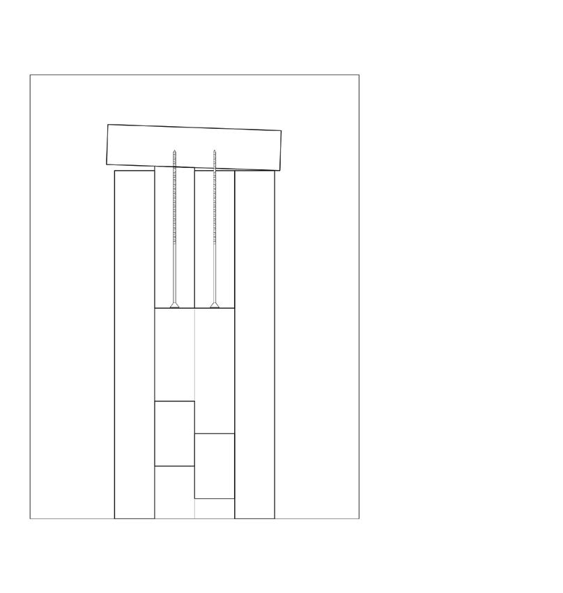
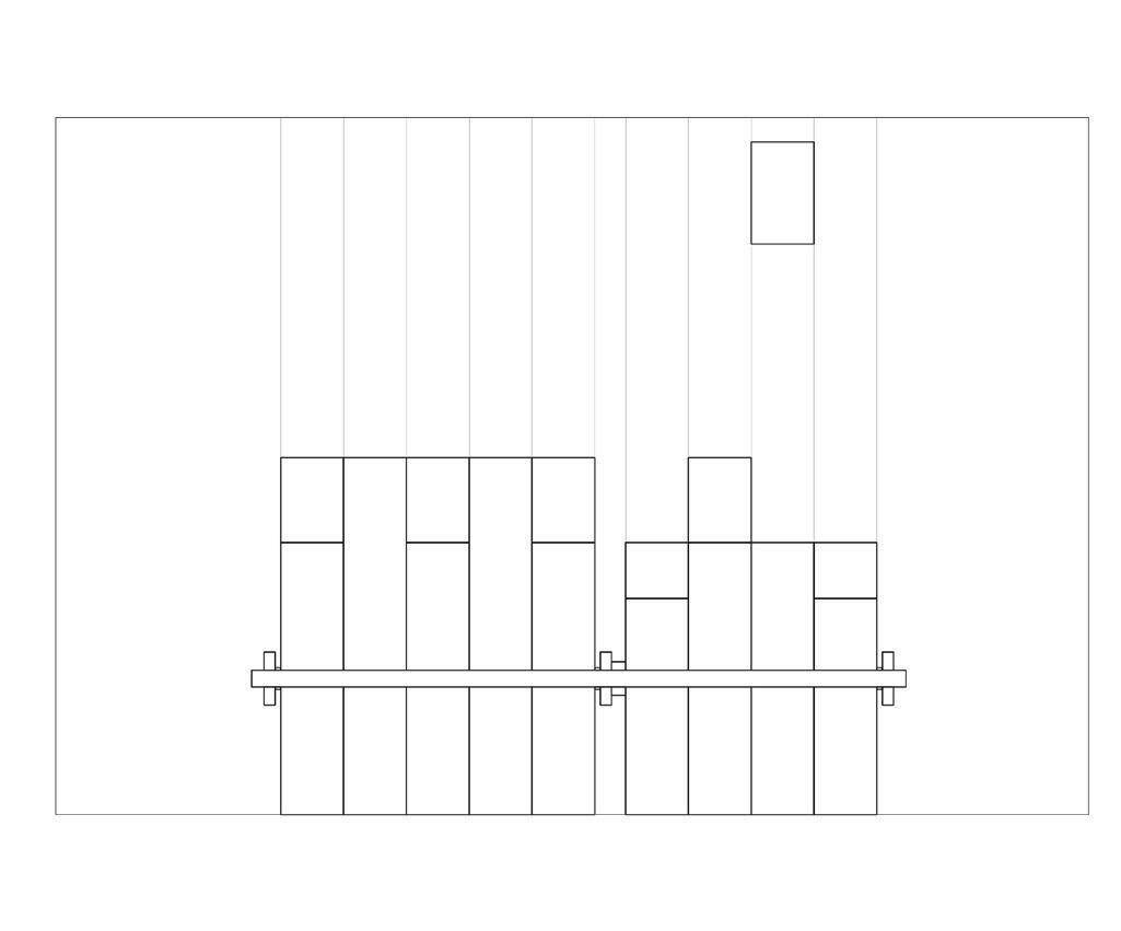
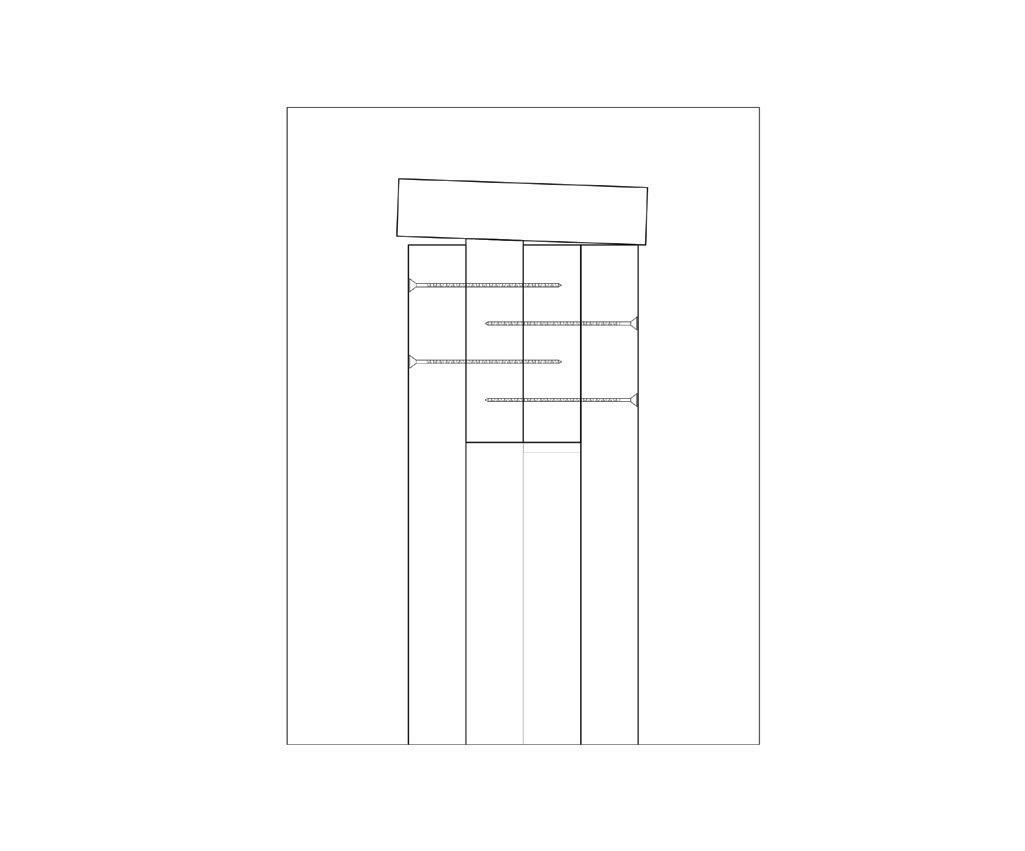
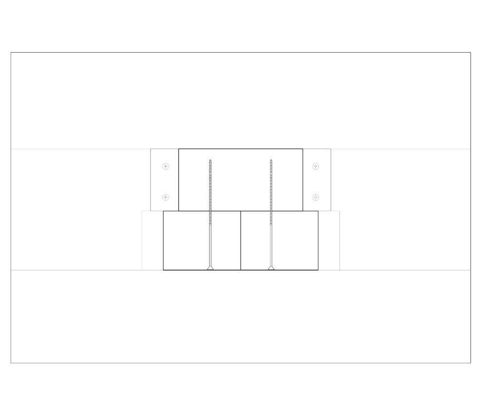
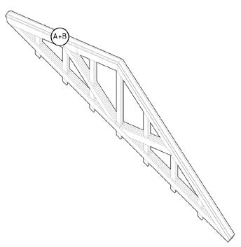
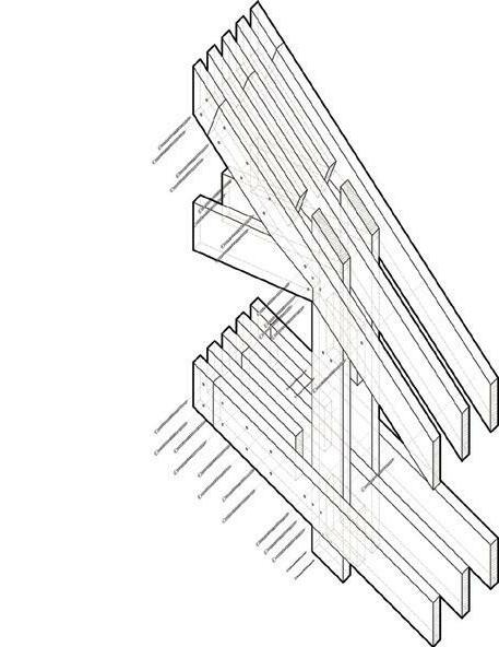
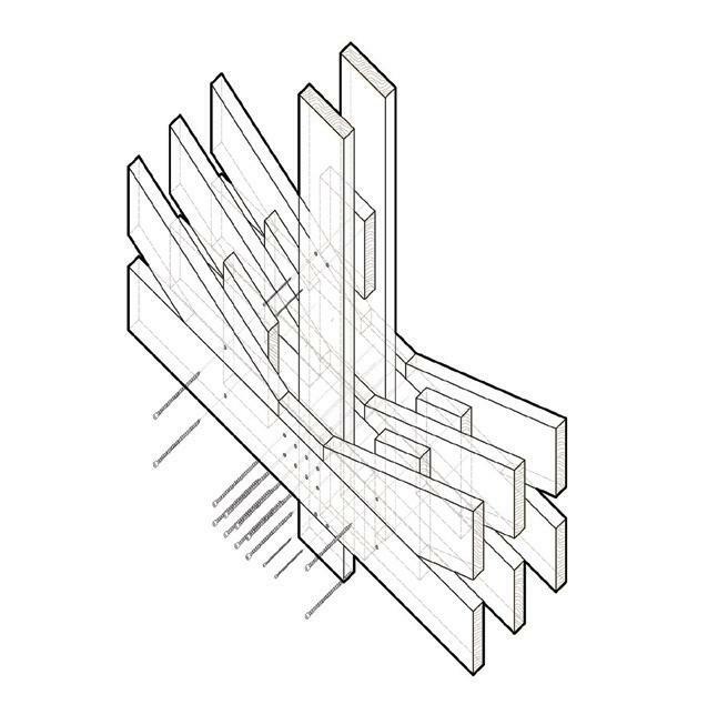
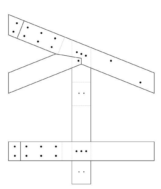
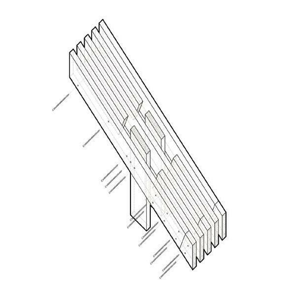
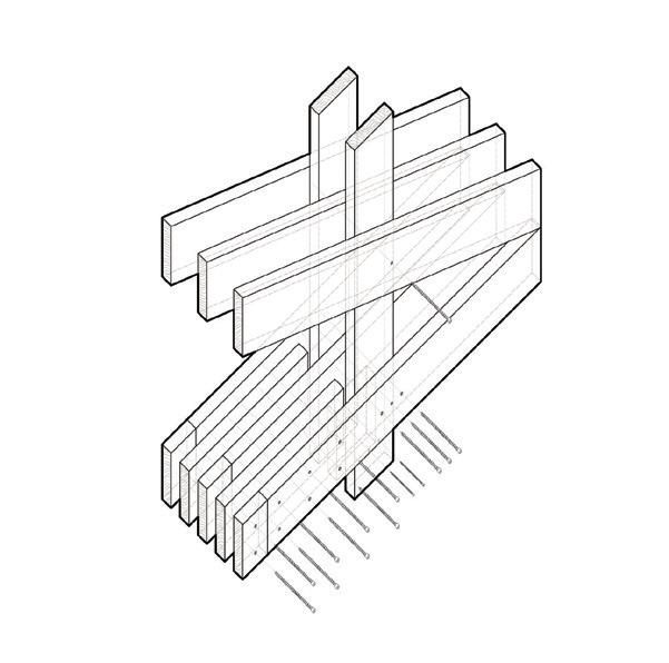
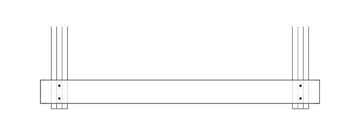
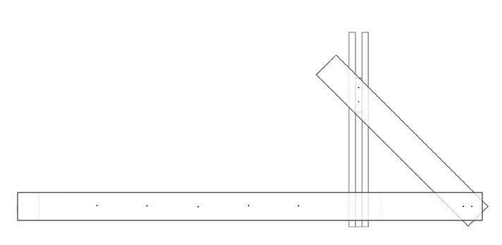
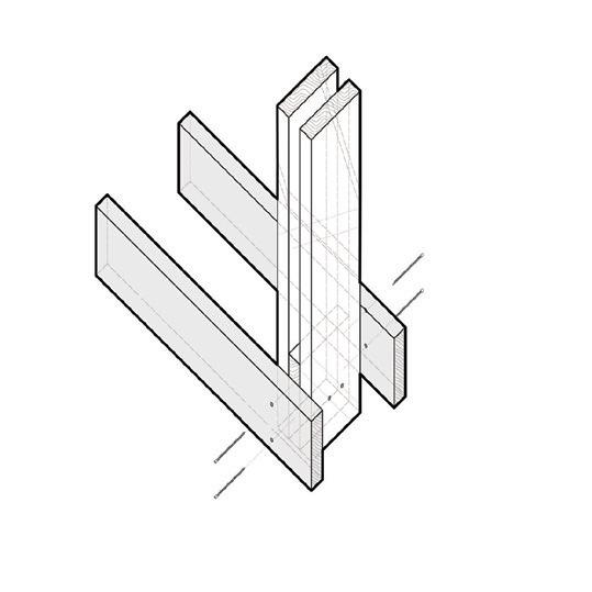
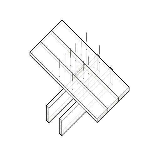
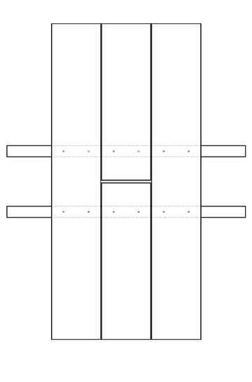
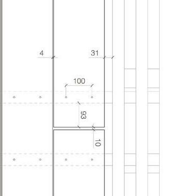
Bridge of Truss.T 77 82 truss details 1.1 1.2 front elevation detail 1:5 side elevation detail 1:5 constructive detail 1.1 Details
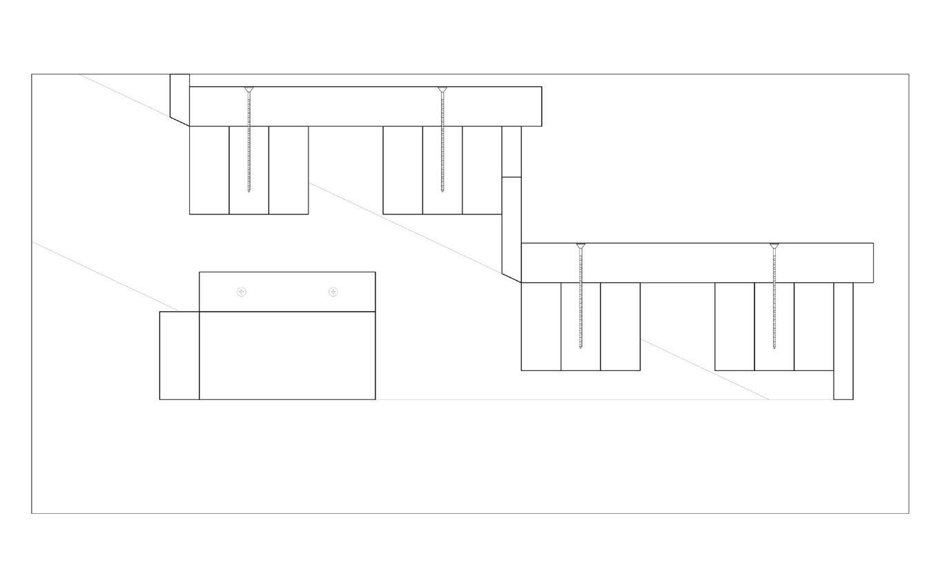
Bridge of Truss.T 78 82 side elevation detail 1:5 front elevation detail 1:5 constructive detail seating1.2details2.1 2.2
Bridge of Truss.T 79 82 constructive detail constructive2.1 detail 2.2
Bridge of Truss.T 80 82
Bridge of Truss.T 81 82
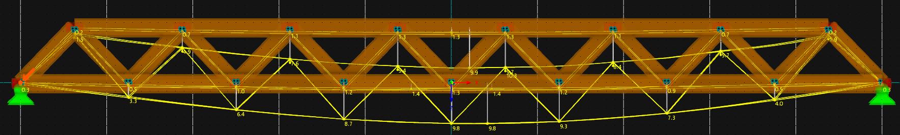
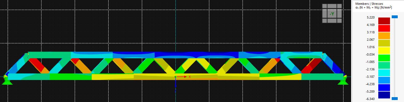
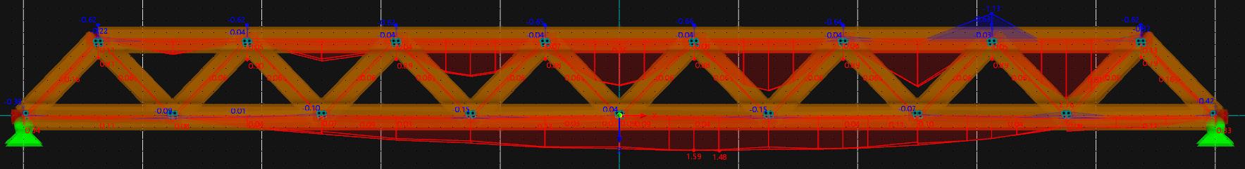
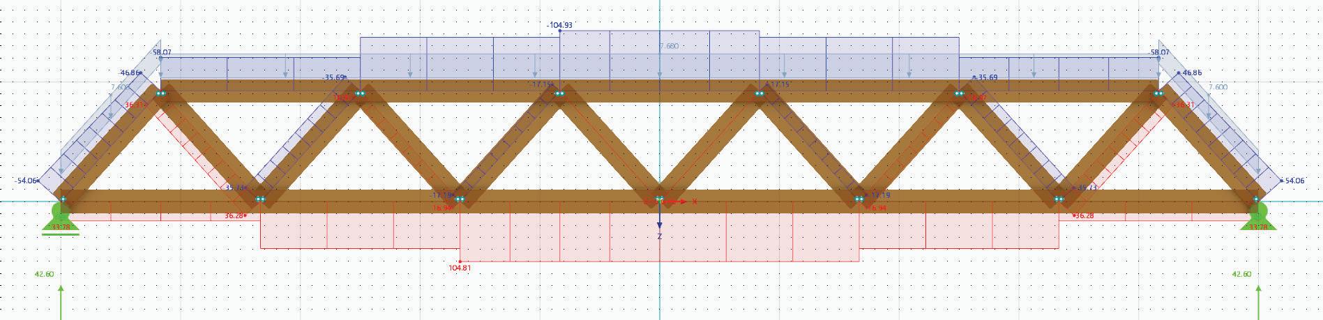
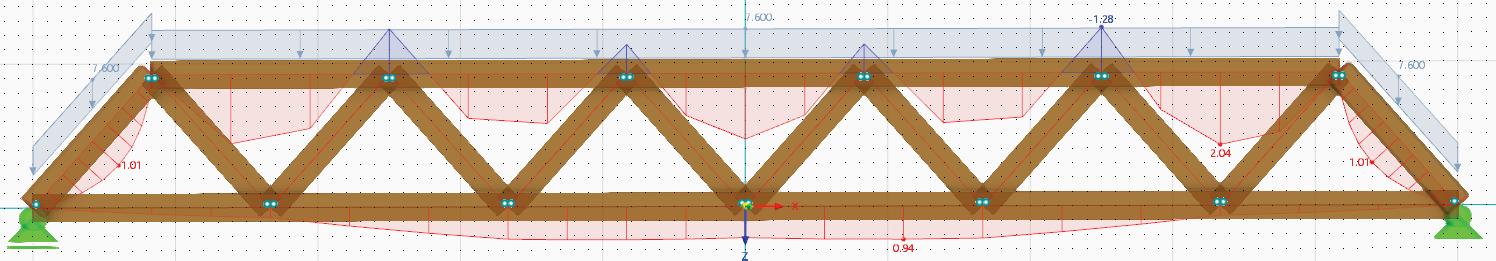
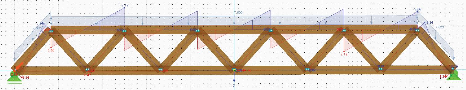
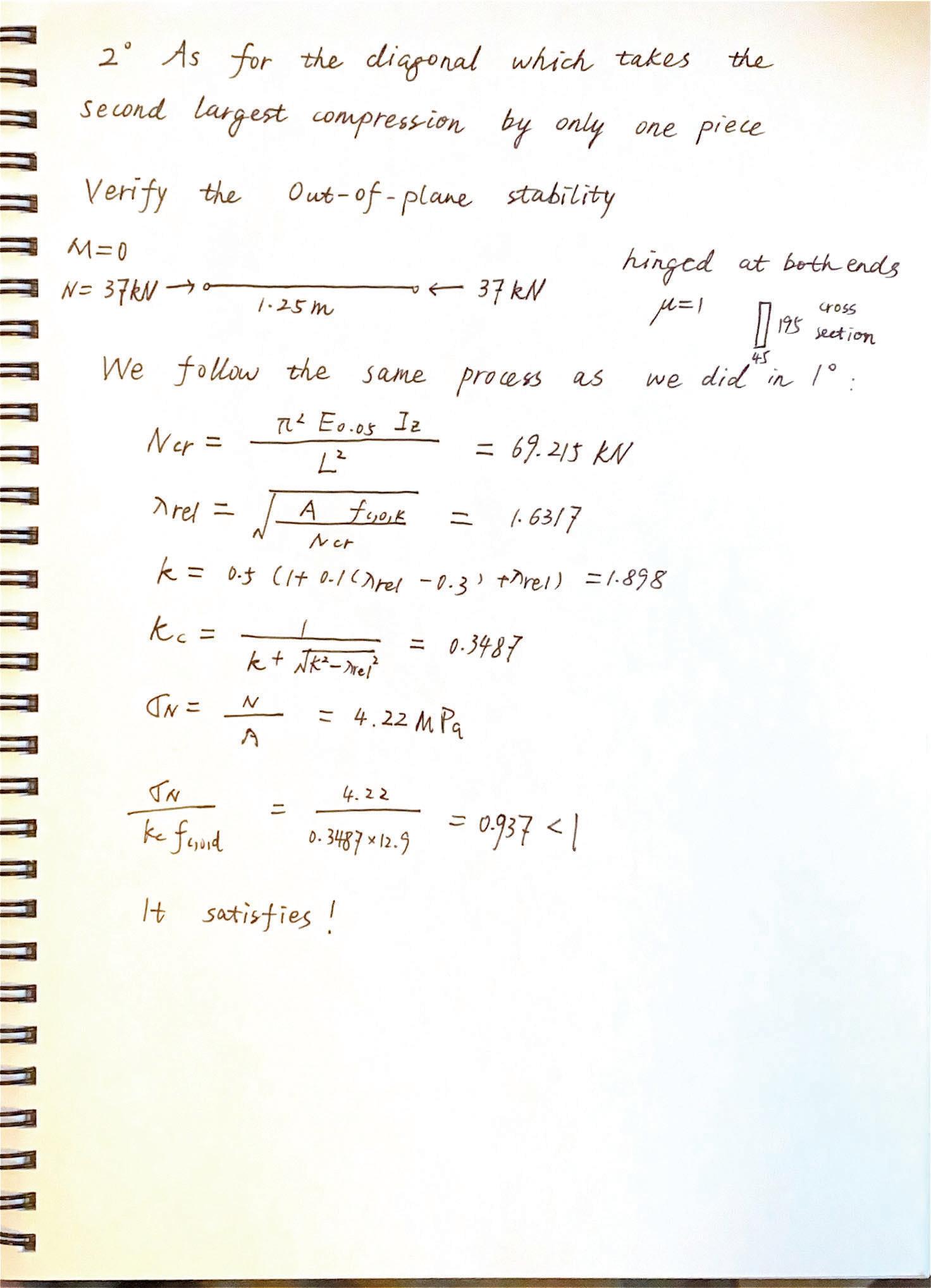
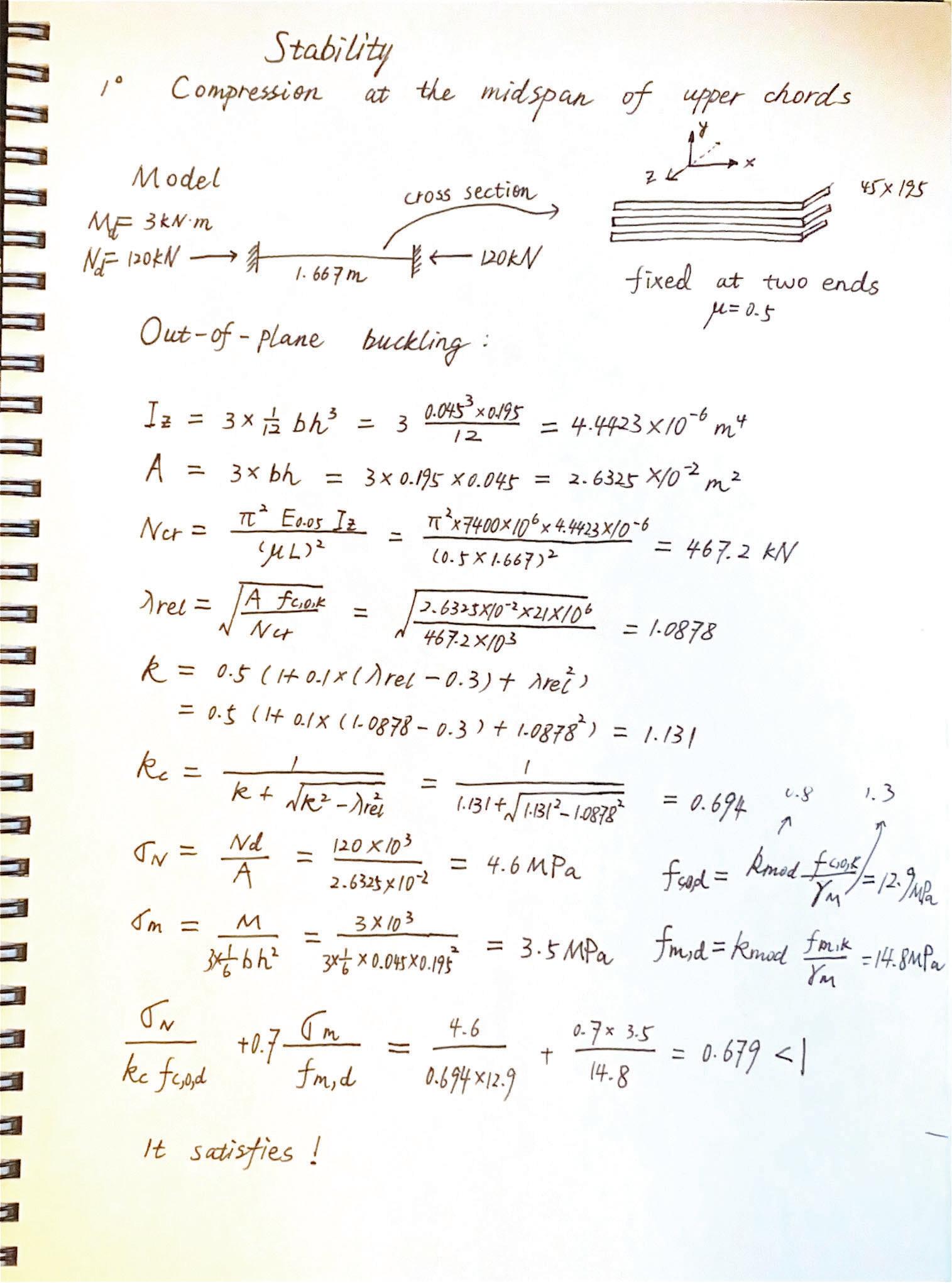
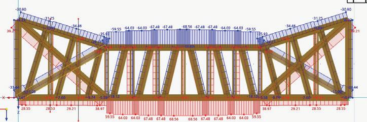
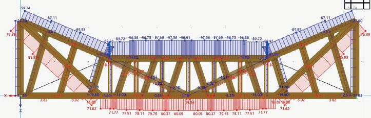
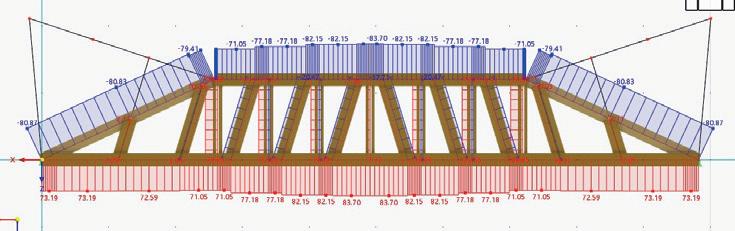
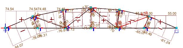
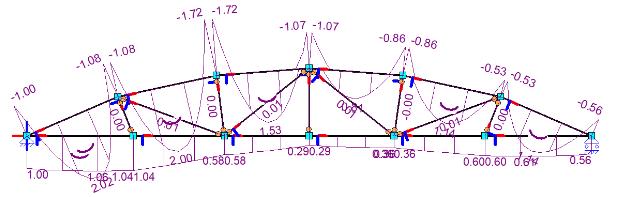
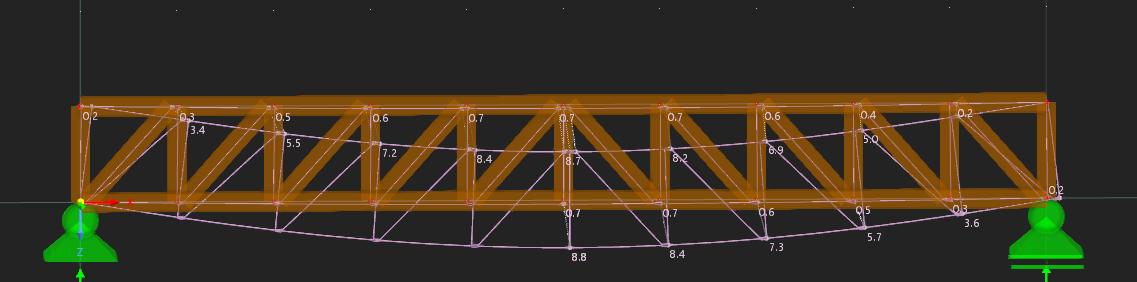
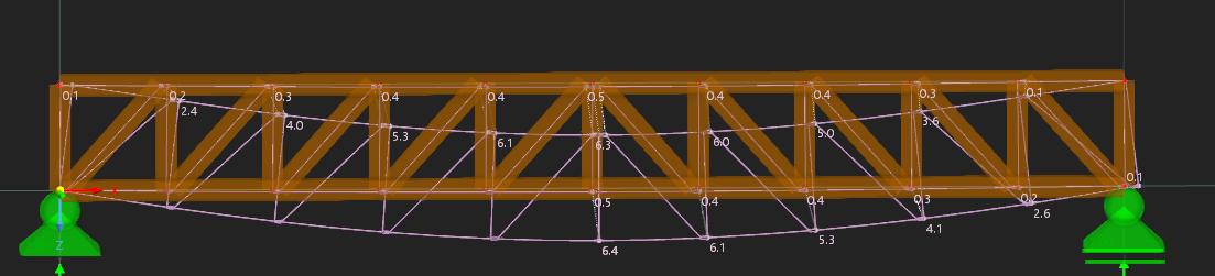
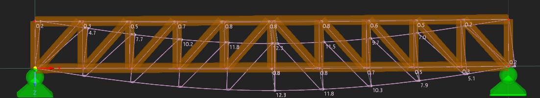
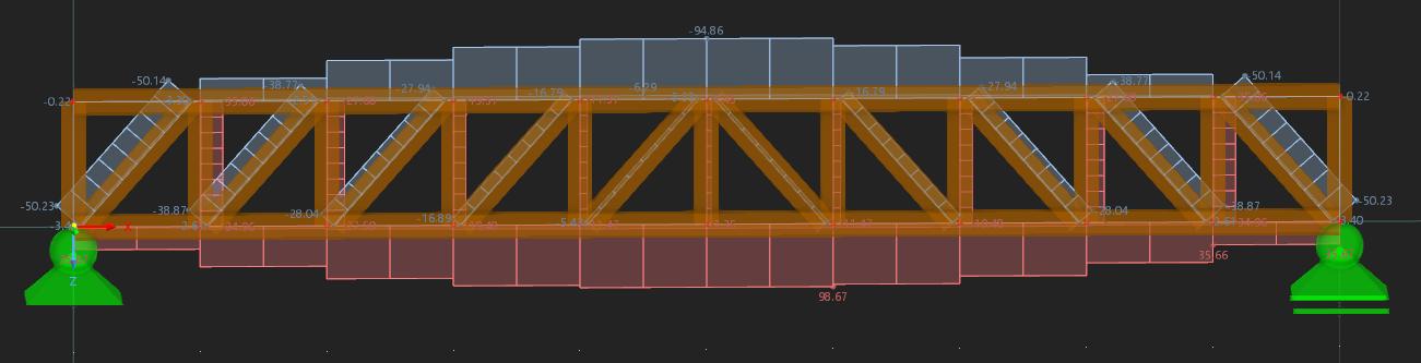
Bridge of Truss.T 82 82 the truss The force was done in ULS with eurocode directly in the program A doublecheck by hand found the design force to be around 10kN/m2 which is about the same as RFEM. The magnitude of the stresses across the truss also matched the expected values in a truss under these load conditions Figure 2. Internal forces and reaction forces as calculated by RFEM 3.3.13 Maximum compression parallel to grain in diagonal member sMubjected to maximum compression where buckling was taken into account, according to 6 3 2 EN 1995 1 1 The maximum compressive force for a diagonal truss was 50 23 kN and resulted in theb3.6 Deflection Deflections in RFEM were done in ULS and SLS with characteristic and quasi permanent load. Figure 3: Deflection in ULS F Figure 5: Deflection in SLS Quasi Permanent State Max Deflection(mm) ULS 12 3 SLS C 6 4 SLS QP 8 8 Table 6: The maximum deflection in ULS SLS Characteristic & Quasi Permanent state in 3.6 Deflection Deflections in RFEM were done in ULS and SLS with characteristic and quasi permanent load Figure 3: Deflection in ULS Figure 4: Deflection in SLS Characteristic Figure 5: Deflection in SLS Quasi Permanent State Max Deflection(mm) ULS 12 3 SLS C 6 4 SLS QP 8 8 Table 6: The maximum deflection in ULS, SLS Characteristic & Quasi Permanent state in 3.6 Deflection Deflections in RFEM were done in ULS and SLS with characteristic and quasi permanent load. Figure 3: Deflection in ULS Figure 4: Deflection in SLS Characteristic Figure 5: Deflection in SLS-Quasi-Permanent State Max Deflection(mm) ULS 12 3 SLS C 6.4 SLS QP 8.8 Table 6: The maximum deflection in ULS, SLS Characteristic & Quasi Permanent state inmm3.6 Deflection Deflections in RFEM were done in ULS and SLS with characteristic and quasi permanent load Figure 3: Deflection in ULS Figure 4: Deflection in SLS Characteristic Figure 5: Deflection in SLS Quasi Permanent State Max Deflection(mm) ULS 12 3 SLS C 6 4 SLS QP 8 8 Table 6: The maximum deflection in ULS, SLS Characteristic & Quasi Permanent state in mm. Internal forces and reaction forces as calculated by RFEM. Deflection in ULS Deflection in SLS-Characteristic Deflection in SLS-Quasi-Permanent The maximum deflection in ULS, SLS-Characteristic & Quasi-Permanent state in mm. Calculations
Bridge of Truss.T 82 82 the truss The force was done in ULS with eurocode directly in the program A doublecheck by hand found the design force to be around 10kN/m2 which is about the same as RFEM. The magnitude of the stresses across the truss also matched the expected values in a truss under these load conditions Figure 2. Internal forces and reaction forces as calculated by RFEM 3.3.13 Maximum compression parallel to grain in diagonal member sMubjected to maximum compression where buckling was taken into account, according to 6 3 2 EN 1995 1 1 The maximum compressive force for a diagonal truss was 50 23 kN and resulted in theb3.6 Deflection Deflections in RFEM were done in ULS and SLS with characteristic and quasi permanent load. Figure 3: Deflection in ULS F Figure 5: Deflection in SLS Quasi Permanent State Max Deflection(mm) ULS 12 3 SLS C 6 4 SLS QP 8 8 Table 6: The maximum deflection in ULS SLS Characteristic & Quasi Permanent state in 3.6 Deflection Deflections in RFEM were done in ULS and SLS with characteristic and quasi permanent load Figure 3: Deflection in ULS Figure 4: Deflection in SLS Characteristic Figure 5: Deflection in SLS Quasi Permanent State Max Deflection(mm) ULS 12 3 SLS C 6 4 SLS QP 8 8 Table 6: The maximum deflection in ULS, SLS Characteristic & Quasi Permanent state in 3.6 Deflection Deflections in RFEM were done in ULS and SLS with characteristic and quasi permanent load. Figure 3: Deflection in ULS Figure 4: Deflection in SLS Characteristic Figure 5: Deflection in SLS-Quasi-Permanent State Max Deflection(mm) ULS 12 3 SLS C 6.4 SLS QP 8.8 Table 6: The maximum deflection in ULS, SLS Characteristic & Quasi Permanent state inmm3.6 Deflection Deflections in RFEM were done in ULS and SLS with characteristic and quasi permanent load Figure 3: Deflection in ULS Figure 4: Deflection in SLS Characteristic Figure 5: Deflection in SLS Quasi Permanent State Max Deflection(mm) ULS 12 3 SLS C 6 4 SLS QP 8 8 Table 6: The maximum deflection in ULS, SLS Characteristic & Quasi Permanent state in mm. Internal forces and reaction forces as calculated by RFEM. Deflection in ULS Deflection in SLS-Characteristic Deflection in SLS-Quasi-Permanent The maximum deflection in ULS, SLS-Characteristic & Quasi-Permanent state in mm. Calculations