14 minute read
LCA ASSUMPTIONS & CHALLENGES
Biogenic carbon, which is produced in natural processes by living organisms, is derived from the atmosphere and is part of a short-term carbon cycle . On the other hand, fossil-fuel based non-biogenic carbon is part of a long-term carbon cycle. It is derived from the earth and is released into the atmosphere permanently, rather than cycling into and out of the atmosphere like biogenic carbon. Sequestered carbon that is retained within wood for less than one hundred years, is considered temporary carbon storage and does not influence the net LCA calculation. If it is retained for more than one hundred years, it is considered permanent carbon storage (Hoxha et al., 2020). This permanent carbon storage is also known as biogenic carbon and produces a net negative impact in a LCA calculation.
A Life Cycle Assessment (LCA) identifies, quantifies, and assesses environmental impacts from raw material extraction through disposal (Elcock, 2007). When conducting an LCA on a mass timber building, biogenic carbon accounts for a significant portion of the benefits of this construction type. Carbon is retained in the wood fiber of a mass timber component throughout its useful life. At the end of its life, if wood is incinerated or left to decay in a forest, this carbon is released back into the atmosphere. If the wood is reused or recycled, this carbon is retained throughout its second life.
Quantifying the benefits of biogenic carbon is challenging. This is due to uncertainty and variability surrounding forestry practices, transportation distances, and end-of-life scenarios. The industry recognizes that to optimize the potential environmental benefits of mass timber construction, wood should be sustainably sourced and transportation distances should be limited as much as possible. Compared to steel and concrete, extraction and manufacturing of mass timber has approximately 50% of the global warming impact of steel or concrete (Feitel, et al., 2021) We also know that the environmental impact of end-of-life scenarios for mass timber can vary significantly, as is illustrated in Figure I. End-of-life scenarios for concrete and steel are easier to predict because of their longevity of use, the availability of precedent data, and because methods for recycling are wellestablished. Steel is relatively easy to recycle and typically contains a high amount of recycled content. On the other hand, concrete structures are difficult to adapt and recycle, so many concrete buildings are demolished to make way for new construction. Wood fiber can be repurposed a variety of ways at the end of its life – incineration, recycling, reuse, and landfilling -- each option with a different level of environment impact. Incineration (without methane recapture or energy recovery) produces a nearly instantaneous release of carbon, resulting in net positive emissions. Alternatively, adaptive reuse or deconstruction and reuse of mass timber components has the most beneficial net cooling effect.
The Time Value of Carbon
There is not yet clear industry guidance on whether biogenic carbon should be included in LCA calculations for projects that include engineered wood products. This disagreement is centered around what happens to these products at the end of their useful lives. Those who advocate for biogenic carbon to be excluded from LCA calculations cite the level of uncertainty surrounding end-of-life, while others argue that most wood products will decompose or be incinerated in this stage, thus releasing the CO2 back into the atmosphere.
Those advocating for the inclusion of biogenic carbon in LCA calculations argue that within a typical building’s lifetime, most biogenic carbon will not have been released to the atmosphere, resulting in some long-term storage (Arup, n.d.). Additionally, not all wood within a landfill decomposes within the timeframe of an LCA study and some amount of this waste could be considered permanently sequestered (Arup, n.d.).
The ISO international standard recommends that biogenic carbon be accounted for as a credit, resulting in net negative carbon storage in Stage D if wood is sourced from sustainably managed forests ( International Organization for Standardization, 2017). Wood sourced from the U.S., Canada, or from third-party certification programs fall within this classification.
What this approach does not account for is the time value of carbon. Similar to investing money, the carbon that is released into the atmosphere today compounds over time. For example, 1,000 kg of CO2 emitted into the atmosphere today has a higher global warming potential than 1,000 kg of CO2 emitted in 50 years (Long-Term Biogenic Carbon Storage, n.d.). This implies that a dynamic approach to biogenic emissions, rather than a static approach like the ISO standard recommends, would be helpful in calculating the full benefits of mass timber reuse and deconstruction
(Long-Term Biogenic Carbon Storage, n.d.). This topic also highlights the importance of designing mass timber buildings with lifespans that exceed the typical 60–100 year average building lifespan.
Research conducted by Dr. Edrit Hoxha, a professor at Aalborg University and an expert in Life Cycle Analysis methods found that, for a wood product, carbon neutrality is achieved in a storage time of about half of the rotation period [of the forest it is sourced from] (Hoxha et al., 2020).” Similar work has been done by Will Hawkins, a lecturer in structural engineering design at the University of Bath whose research focuses on pathways to zero-carbon building structures. His work indicates that biogenic carbon benefits are closely tied to forestry rotation periods for timber products. In a series of calculation Hawkins ran, he found that if wood is sustainably sourced with replanting and carbon absorption, and the structure is in use for one-hundred years, it would be carbon-negative for half of its lifetime [or double an assumed fifty-year harvest cycle]. Alternatively, the same structure demolished after forty years would never reach carbon negative (Hawkins, 2021). This research demonstrates that if mass timber components are designed to be used for over one-hundred years, future buildings that reuse these components after that time could be structurally carbon negative from day one.
To supplement ISO standard recommendations, The Wood Products Council and the Carbon Leadership Forum recommend reporting the amount of biogenic carbon stored in the wood products separate from LCA calculations (How to Include Biogenic Carbon in an LCA, n.d.). Accounting for this value separately allows us to quantify future benefits if the
Definitions And Abbreviations
Non-biogenic Carbon: Derived from the earth, fossilfuel based, and is released into the atmosphere permanently, rather than cycling into and out of the atmosphere like biogenic carbon (The Carbon Leadership Forum, 2019).
Carbon Sequestration: The process of extracting carbon from the atmosphere and storing it in a longterm form. Sequestered carbon can be reported as a negative carbon “emission” (The Carbon Leadership Forum, 2019).
Temporary Carbon Storage: Storage within a 100year period (Hoxha et al., 2020).
Permanent Carbon Storage: Storage for more than 100 years (Hoxha et al., 2020).
Life Cycle Assessment (LCA): A systematic process for identifying, quantifying, and assessing environmental impacts throughout the life cycle of a product, process, or activity. It considers energy and material uses and releases to the environment from ‘cradle to grave’ (Elcock, 2007).
Cradle-to-Grave: From raw material extraction through manufacturing, transportation, use and disposal (Elcock, 2007).
building’s life is extended or the wood products are reused. New tools including Upstream and the WWF Bioenergy Carbon Footprint Tool can be used to run custom scenarios to sharpen projections on the environmental impact of wood sourcing and certification, transportation, and the benefits of adaptive reuse or deconstruction to direct decision-making during the design process.
Not All Reuse is Equal
When considering end-of-life scenarios, it’s important to understand that not all reuse outcomes are comparable. In line with the concept of cascading, the highest and best use of a mass timber product should be maintained as long as possible. The possible end-of-life scenarios for mass timber exist along a spectrum as shown below.
Lowest to highest value reuse alternatives:
Incineration
Mass timber waste can be incinerated, resulting in a burst of carbon being released into the atmosphere. When the time value of carbon is considered, this scenario has the potential to wreak the most havoc on the atmosphere. Mass timber products containing adhesives will contribute more to net warming than those that do not when incinerated (Our Endangered World, 2023).
Landfill
Landfilling is another low value end-of-life outcome for mass timber construction. In a landfill, some portion of the mass timber waste will slowly decay, releasing biogenic carbon back into the atmosphere. However, some of the wood will not decompose within the timeframe of an LCA study, and could be considered permanently sequestered (Arup, n.d.).
Recycling
Recycling mass timber into mulch is a form of downcycling. This alternative requires additional processing and associated carbon emissions. Mass timber products containing glues may not be a good candidate for this alternative if they contain glues that have potential for leaching (Our Endangered World, 2023).
Deconstruction for Reuse
The second highest value end-of-life scenario for mass timber is deconstruction for reuse of structural components. Ideally, mass timber elements can be reused as a structural component in a new building or to repair a component in an existing building. The next best alternative is for these elements to be reused for slightly lower value alternatives, such as furniture and interior finishes.
Adaptive Reuse
The highest value end-of-life scenario for mass timber is adaptive reuse of the whole building structure. This scenario requires minimal demolition, deconstruction, or reprocessing, and consequently, carries the greatest carbon benefits. To improve the likelihood that mass timber buildings will be adaptively reused, the original design should be aspirational, of high-quality, and should anticipate future change by planning for flexibility.
Alastair Reilly, a Principal at William McDonough Architects and a thought leader on circular economies, advocates for designing buildings for both whole building and component reuse. Anticipating that the demand for housing will increase with growing populations, Reilly designs all new construction office buildings within a 30’ structural grid, which is the standard for multifamily housing, rather than the 20’ structural grid that is more common for office buildings. This adjustment makes the building more adaptable to future demands with minimal investment and will likely have a much longer lifespan as a result (A. Peitz, personal communication, April 14, 2022).
Adaptive reuse and deconstruction for reuse are by far the preferred end-of-life scenarios to optimizing the environmental benefits of mass timber construction. Recycling is a good alternative when adaptive reuse and component reuse is not possible. Other outcomes, including landfilling and incineration, result in loss of value as well negative environmental impacts, and should only be considered when other options have been exhausted (Bergman et al., 2013).
Recommendations
To promote adaptive reuse and deconstruction for reuse, there are several strategies we can apply during the design process. These strategies fall into five categories:
1. Structural Design
2. Finishes + Built-Up Assemblies
3. Systems Distribution
4. Moisture Management
5. Documentation
1. Structural Design
A. System and Program Layout
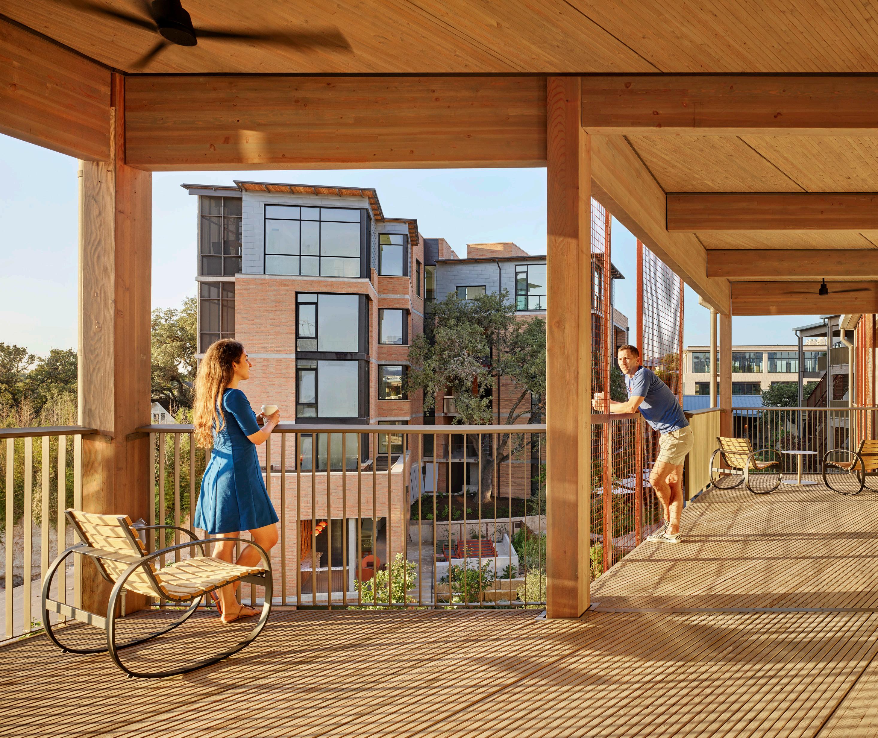
The structural system of a mass timber building should be designed for future adaptability as well as deconstruction. This means designing using large, flexible grids that go above and beyond the needs of first-life program. Grid spans and structural elements should be kept standardized, repetitive, and interchangeable as much as possible to optimize future opportunities for component reuse. This will simplify the initial construction process, and in turn, simplify the deconstruction process.
B. Joint & Connection Design
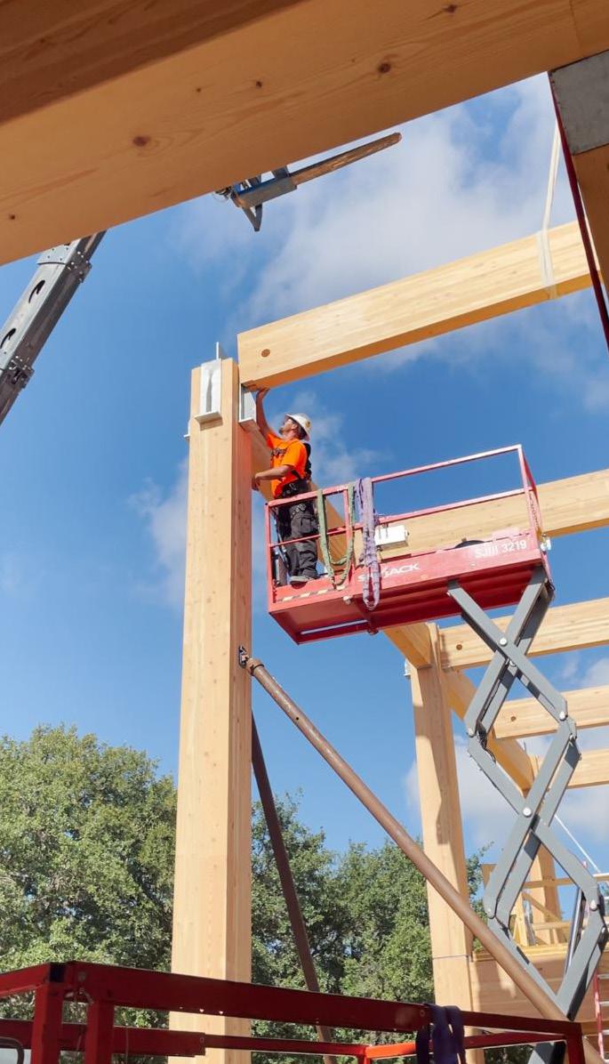
To accommodate future deconstruction, mass timber connections should be standardized and interchangeable, as well as easy to install (and thus to deconstruct). Avoiding custom or high-capacity connections will facilitate a clear, quick, and easy deconstruction process using standard tools that requires less labor. Connections that require sequential installation should be avoided because they are not intuitive and are likely to stall the deconstruction process or result in damage to structural components. Generally, easy assembly is linked with easy disassembly (Hradil et al., 2014). When permitted by code, connections should be designed with the deconstruction process in mind by keeping connectors exposed .
Screws, bolts, and metal plate connectors facilitate the deconstruction process because they can be removed with minimal damage to the mass timber and connector elements (Hradil et al., 2014; Sandin et al., 2022). Nails require manual removal, are more time-consuming to re- move, are likely to fail in bending, and therefore are difficult to remove without damaging mass timber components or breaking the fastener (Hradil et al. 2014). Limiting the quantity of mechanical fasteners required for installation is also helpful because it will limit the amount of labor and cost required to install or deconstruct the connection. It is reasonable to expect that salvage mass timber components will be processed similarly to salvage steel. After a steel component is salvaged, its ends are often trimmed off to provide a square, clean base that can be used for a new connection.
C. Topping Slabs
When designing for deconstruction and reuse potential, dry assemblies are preferred over wet assemblies. This concept also applies to cast-in-place topping slabs. Concrete topping slabs, while typically separated from direct contact with the mass timber deck using a membrane or acoustic mat, still must be demolished, and removed before deconstruction of the mass timber is possible. Every additional step that must be completed before recovering the mass timber reduces the likelihood of deconstruction and component reuse.
Precast concrete panels provide an alternative to the topping slab that does not require demolition before deconstruction. However, the immense weight of these precast panels makes installation or deconstruction labor intensive and costly when compared to cast-in-place systems.
Seismic environments pose a unique challenge that often leads to reliance on a concrete topping slab to perform as a diaphragm and provide lateral support. Alexis Feitel, a structural engineer and Team Carbon Unit Director at KL&A, notes that their team always advocates for using the mass timber deck as the diaphragm in seismic environments rather than relying on a concrete topping slab. Feitel notes that this approach provides options for using dry alternatives to cast-in-place concrete and provides access to the deck without demolition, which is beneficial for ensuring future reconfigurability of systems (Allison, Peitz, personal communication, May 25, 2023).
2. Finishes and Built-Up Assemblies
A. Acoustic Assemblies + Vibration Control
A cast-in-place topping slab is often recommended to meet minimum acoustic requirements or to address vibration concerns. However, there are now a variety of topping options that achieve high levels of acoustic performance and meet minimum mass requirements to address vibration using dry assemblies. These floor assemblies make use of cement board, plywood, gypsum fiberboards, bio-based granules, raised access floors, and a variety of acoustic products to achieve these ratings. When using dry assemblies, seams should be thoughtfully considered to anticipate equipment leaks and cleaning methods to ensure that moisture cannot seep through the assembly.
B. Material Interfacing
Similar to the challenges encountered during residential deconstruction efforts, wet assemblies that include adhesives present unique challenges. In many cases, the effort and cost required to remove adhesive materials from a mass timber element outweighs the potential benefits for reuse.
Building D(emountable), built in Delft, Netherlands, is an excellent example of deconstructable design using dry assemblies as an alternative to the topping slab and at the exterior envelope. This office building was designed to be relocated and rebuilt or to be deconstructed so that components could be used on future projects. Rather than using a cementitious topping slab on top of their laminated veneer lumber (LVL) deck, the topping selected is an “easily removable bio-based screed…filled with gravel- like granules in a cardboard honeycomb” and topped with gypsum fiberboards as shown in Figure J. (Critescu et al., 2020). This combination of materials achieves a density that contributes to acoustic performance and serves as a diaphragm. This commitment to demountable construction is carried to the exterior envelope, which is composed of dry mounted prefabricated panels (Critescu et al., 2020). It is important to note that the install process for this dry assembly was likely more labor and cost intensive than a cast-in-place concrete alternative. However, this difference will be made up in the deconstruction process since no demolition will be required for disassembly.
C. Finishes and Coatings
Additional finishes beyond a protective clear coat should be avoided if possible. In a deconstruction scenario, finishes will require additional processing to remove the finish to make it suitable for reuse, potentially deterring recovery of the mass timber.
3. Systems Distribution
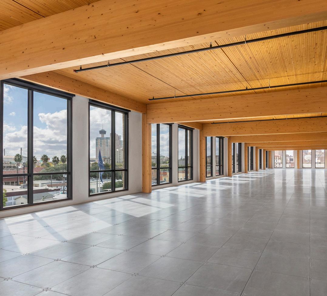
System distribution strategies should be designed to accommodate reconfigurability and adaptability , rather than customized to accommodate first-life systems. One way to do this is to use a raised access floor system, like that used on the Soto office building in San Antonio, TX (Figure K.) A raised access floor comes in a variety of depths to accommodate a variety of systems, including air distribution. Additionally, it can be reconfigured regularly with no impact on structural components.
Alternatively, the deck can be designed with larger voids that can accommodate new and future systems. The PAE Living Building project in Portland, OR incorporates 2’ wide, shallow raceways between CLT panels, spanned by a plywood panel to create a void for conduit and sprinkler lines as shown in Figure N. (Woodworks Innovation Network, n.d.) After systems were installed, the raceway was covered with panels and fixtures and devices were installed (Libby, 2022).
At the Wood Innovation Center in Prince George, Columbia, CLT panels are staggered to create voids within the ceiling and below the floor as shown in Figure O. At the ceiling, these gaps are screened by gapped wood panels. At the floor, this gap is spanned by a plywood panel that is covered in an acoustic underlayment and finished with carpet tile. Since there is not a concrete topping, this raceway remains accessible for maintenance or future updates (Wood Innovation and Design Centre, 2015).
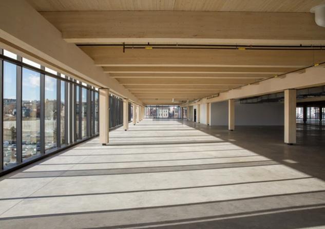
Platte Fifteen, a mass timber office building in Denver, Colorado, uses another approach to accomplish a similar level of flexibility as shown in Figure L. and Figure M. below.
Girders run longitudinally. The central bay of the building is free from these girders, allowing systems to run within the depth of the beam structure. Joists are stacked on top of girders, running perpendicular to these systems. Systems run outward from the central bay out to the perimeter of the building through voids created in the stacked structure. This approach eliminates the need for cutouts and provides a hyper flexible distribution strategy.
3’’ reinforced concrete topping slab conduit and sprinkler lines
2’-0’’ fire protection
7/8’’ plywood sheathing
3-play cross-laminated timber glulam column beyond conduit and sprinkler lines ductwork conduit and sprinkler lines carpet
CLT panel concrete topping slab rigid insulation
2-ply plywood
1/4’’ acoustical underlayment
3-ply CLT panel glulam beam beyond
4. Moisture Management
In addition to structural and connection design, designers should consider moisture management strategies to ensure that the quality and capacity of the mass timber components is not diminished over time. It is understood that exposure to high levels of moisture can reduce the structural capacity of mass timber components. This is reflected in the evaluation of structural components at ‘Building Two,’ which found no loss in structural capacity of mass timber elements that remained protected from moisture over seventy-six years, and a significant loss in structural capacity of the unit exposed to moisture during that time (Rammer & Moura, 2013). Similarly, when regrading timber structural elements for reuse, if the component was previously used in an exterior application or was heavily loaded, the strength grade should be reduced by two steps (Hradil et al., 2014).
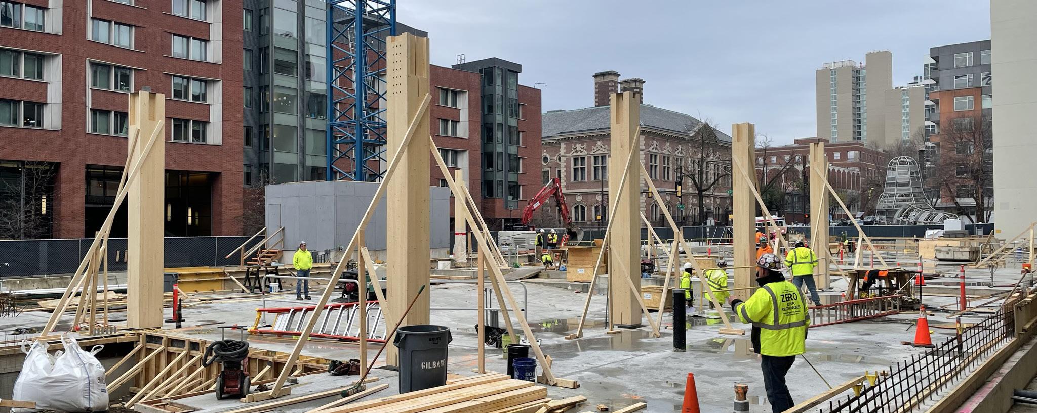
Treated mass timber has limited end of life recovery scenarios. Treated timber is very rarely sorted and is usually landfilled (Love, 2007). Methods used to process treated timber and make it safe for recycling, landfill disposal, or incineration are time consuming, expensive, and not generally feasible (Love, 2007).
In addition to levels of exposure intended within the original design, it is also important to anticipate unintended sources of moisture exposure. Every component in the exterior envelope may pose a threat to mass timber if it is not maintained over time. It is important to consider the lifespan of each element, such as a vapor barrier with a lifespan that is less than fifty years. It is best to select materials with longer lifespans to minimize the opportunities for unintended exposure over the lifetime of a building


