2 minute read
3.2.2 Girder A2001 Web Stiffeners Prevent Flange Failure and Girder Walk-off


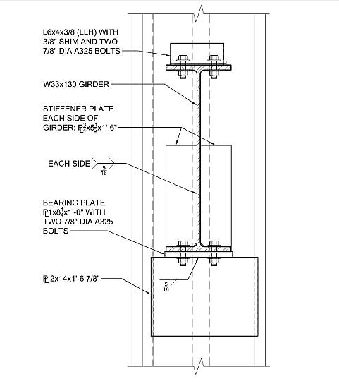
Figure 3.6 Section view at Floor 13 of Column 79 and girder A2001 seated beam connection, which shows stiffener plates on girder A2001 (Data from Frankel Steel Limited, 1985, Drawing 9114; figure prepared by Brookman, 2012).
3.2.2 Girder A2001 Web Stiffeners Prevent Flange Failure and Girder Walk-off
Advertisement
A separate model was generated to determine what would happen if girder A2001 were able to somehow move past the Column 79 western side plate. This model removed the side plate protrusion that we found in our previous analysis would interfere with the girder’s lateral travel. The results are shown in Figures 3.7 and 3.8. To perform this analysis, the coefficient of thermal expansion of the steel used for beams K3004, C3004, B3004, and A3004 was increased by approximately 40% to 11.5 x 10⁻⁶ in/in/°F
to ensure the girder’s web moved a significant distance beyond the seat. This modification to the modeling parameters underscores the fact that under a realistic assumption of the coefficient of thermal expansion, beams K3004, C3004, B3004, and A3004 would not expand far enough to push the girder’s web beyond its seat.
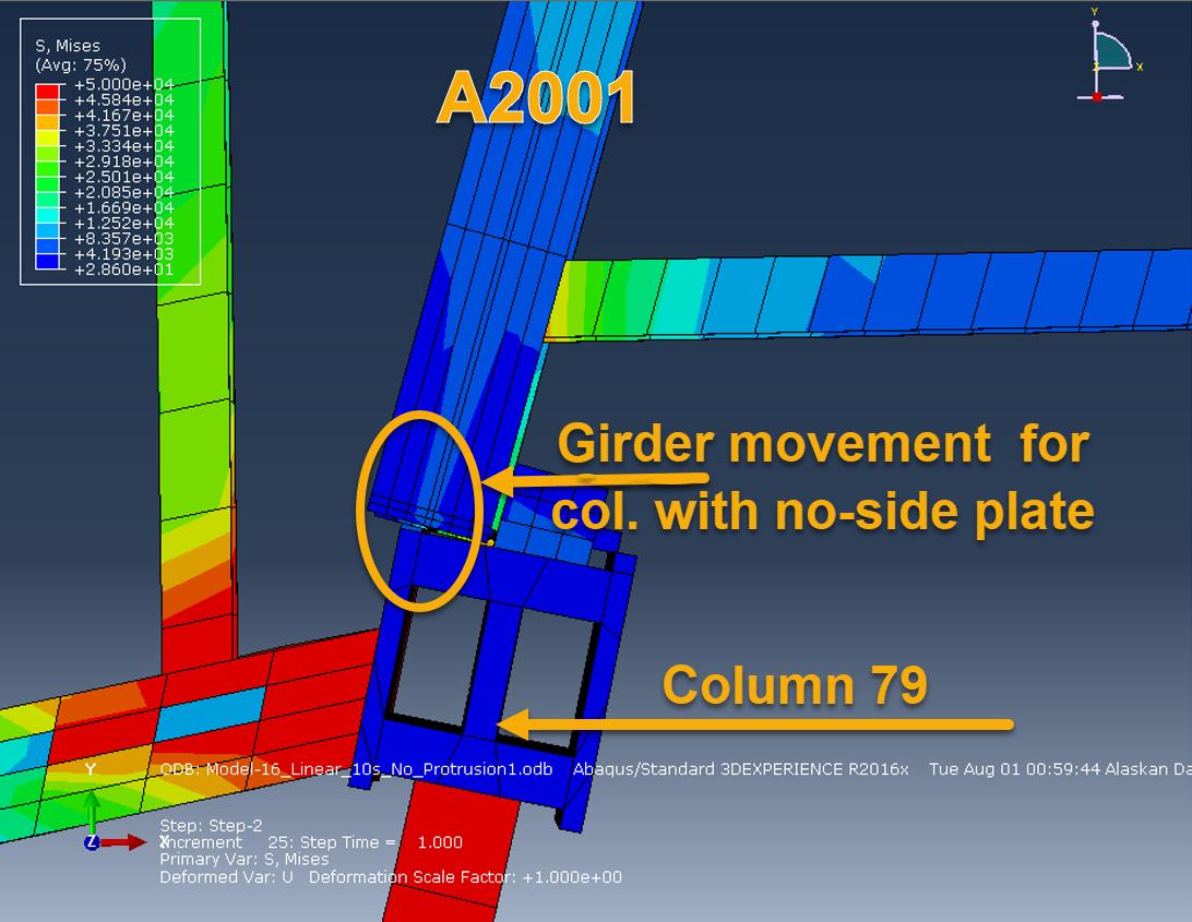
Figure 3.7 Plan view shows girder A2001 being pushed laterally past notched western side plate.
It is important to note that the analysis performed by NIST did not include the ¾ inch thick x 5.5 inch wide x 18 inch high partial height web stiffeners on girder A2001. Released fabrication shop drawing Frankel 9114 shows that the stiffeners were part of that structural member (Frankel Steel Limited, 1985). In addition to stiffening the web, these stiffeners significantly increase the bending resistance of the flange and would have prevented it from failing due to flexure (assuming the girder were somehow able to bypass the column side plate). Note that the small amount of high stress on the corner of the girder’s flange is not in a load bearing area. This stress is due to the girder flange being slightly compressed in the axial
direction by its contact with the column flange when the girder is thermally expanded. Figure 3.8 shows that the stresses in the girder flange and stiffener are not sufficient to cause the flange to fail. The expanded girder could not possibly be shortened enough to come off the seat axially or to cause the seat to fail in bending. The edge of the support plate, which supports the bearing seat, is 3.8" from the face of the column flange. The two erection bolts between the girder and the bearing plate were claimed by NIST to have broken due to thermal expansion and are not shown for clarity.
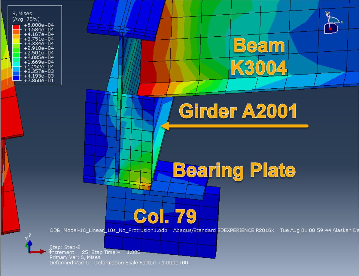
Figure 3.8 Analysis showing girder web A2001 pushed laterally past the bearing seat at Column 79. The column is removed for clarity.
Figures 3.9 and 3.10 below, which are from the NIST report, show that the NIST report’s drawing and analysis figures omit these web stiffeners. Figures 3. 5 and 3.6 show the actual configuration.


