RAISED
FLOOR STETEMS
CP Modular
mkelectric.co.uk
Accessory Modules The conduit entry faces are integral with the accessory plate, enabling quick termination to the power or data plate and facilitates the remaining part of the back box to be fitted quickly with no risk to wiring being damaged.
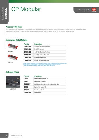
Unserviced Data Modules
CRM21201
CRM21215
Part No.
Description
CRM21201
4 x LJU6C Apertures (Knockouts)
CRM21301
6 x LJU6C Apertures
CRM21500
4 x ST Fibre Connector Apertures
CRM21215*
4 x LJU6C Aperture Wave Plate
CRM21117
4 x Alphasnap Apertures
CRM31501
2 x Euro 50 x 50mm Apertures
Earthing studs are provided on all Unserviced data modules to enable a reliable connection to earth to be made. Earthing Kit CX-10 is recommended for use to ensure the earthing cable is connected correctly. * Larger back boxes are available on request via the Design Service, see page 16.
Optional Extras
LID TETHER
380
mkelectric.co.uk
Part No.
Description
CX-01
Cable Retainers – pack of 10
CX-02
Lid Tether Kit – pack of 5
CX-04GRY
Cord Cap for 265 x 265 and 340 x 265mm Lid – Grey
CX-10
Earthing Kit – pack of 10
CRXKEY
Lock Key – pack of 2
CRM31201
Blank Module
Pre-Configured Range To aid fast and simple product selection, storage and installation, a selection of popular pre-configured floorboxes are available to order: l
2, 3 or 4 module options
l
Supplied with Serviced Power and/or Unserviced Data Plates
l
Choice of standard modules or pre-wired to a tap-off
l
Pre-wired boxes supplied with a 3m tap-off, High Integrity Earthing compliance as standard
2 Module Configuration – 265 x 265mm Floorbox Module 1
Module 2
Module 3
Tap-Off
CRM321
2G Switch Socket Outlet
BLANK
4G DATA PLATE LJU6C
NA
CRM321W
2G Switch Socket Outlet
BLANK
4G DATA PLATE LJU6C
UT33201 GREY 4MM2 3M
MK
RCD
Part no.
RCD
All modules supplied set at 90mm from top of lid to base of module.
MK
3 Module Configurations – 265 x 265mm Floorbox Module 1
Module 2
Module 3
Tap-Off
CRM333
2G Switch Socket Outlet
4G Data Plate LJU6C
4G Data Plate LJU6C
NA
CRM333W
2G Switch Socket Outlet
4G Data Plate LJU6C
4G Data Plate LJU6C
UT33201 GREY 4MM2 3M
CRM334
2G Switch Socket Outlet
4G Data Plate LJU6C
NA
CRM334W
2G Switch Socket Outlet
4G Data Plate LJU6C
UT33201 GREY 4MM2 3M
CRM336
2G Switch Socket Outlet Clean Earth
4G Data Plate LJU6C
NA
CRM336W
2G Switch Socket Outlet Clean Earth
4G Data Plate LJU6C
UT33204 CE RED 4MM2 3M
MK
RCD
MK
RCD
MK
RCD
MK
RCD
MK
RCD
Part no.
All modules supplied set at 90mm from top of lid to base of module
4 Module Configurations – 340 x 265mm Floorbox Part no.
Module 1
Module 2
Module 3
Module 4
Tap-Off
CRM431
2G Switch Socket Outlet
Blank
Blank
4G Data Plate LJU6C
NA
CRM431W
2G Switch Socket Outlet
Blank
Blank
4G Data Plate LJU6C
UT33201 GREY 4MM2 3M
CRM434
2G Switch Socket Outlet
Blank
4G Data Plate LJU6C
NA
CRM434W
2G Switch Socket Outlet
Blank
4G Data Plate LJU6C
UT33201 GREY 4MM2 3M
CRM444
2G Switch Socket Outlet
4G Data Plate LJU6C
4G Data Plate LJU6C
NA
CRM444W
2G Switch Socket Outlet
4G Data Plate LJU6C
4G Data Plate LJU6C
UT33201 GREY 4MM2 3M
All modules supplied set at 90mm from top of lid to base of module.
MK Electric Catalogue
381
FLOOR SYSTEMS
RAISED
CP Modular
Technical Hotline +44 (0)1268 563720
APPLICATION RAISED
FLOOR PRODUCT STETEMS
CP Modular
PRODUCT APPLICATION MULTIMEDIA SOLUTIONS – COMBINATION PLATES
The combination plates provide unrivalled aesthetic enhancement and reduced visual impact on the wall, created when numerous devices are individually installed in one location. Additionally they offer a functional solution for when power, audio visual and data connectivity are required at a single point. There are 10 different configurations offered over 4 of our ranges – Logic Plus, Edge, Elements and Aspect.
382
mkelectric.co.uk
mkelectric.co.uk
RANGE INTRODUCTION
Cablelink Plus Single Pan Box provides an effective interface between services beneath the floor and the office environment.
FEATURES & BENEFITS
Designed to offer robustness and constructed with a single piece metal frame, the floorbox is available with 1, 3 and 4 compartments and a choice of 70mm or 95mm box depths to cater for floor voids of restricted space.
SHALLOW VOIDS ACCOMMODATED
TESTED TO EN 50085-2-2 TO ACCEPT 5000N LOAD SUPPORTS CAT 6 & CAT 7 70mm through the use of the wave plate
With 70mm pan depth ADJUSTABLE DEVICE PLATE To increase wiring space or greater plug top clearance COMPLIES WITH WIRING REGULATIONS Provision of RCD protections supports IET 17th Edition Wiring Regulations SELF-CLOSING LID In accordance with IEC 61534-22
HOW TO SPECIFY A range of 1, 2, 3 and 4 module single pan floorboxes designed to meet EN50085-2-2. Product to incorporate a ratchet self-levelling system enable rapid fitting of the frame and lid. Pan design to incorporate side knockouts and compartment segregation and be available in both 70mm and 95mm pan depths. Product to have a self-closing lid with locking option available. Provision of RCD protection to support compliance to 17th Edition Wiring Regulations.
FLOORBOXES ARE RATED IP2X IN ACCORDANCE WITH BS EN 50085-1 WIDE RANGE OF POWER AND DATA ACCESSORY PLATES 5 YEAR GUARANTEE
MK Electric Catalogue
383
FLOOR SYSTEMS
RAISED
CABLELINK PLUS SINGLE PAN BOX
RAISED
FLOOR SYSTEMS
CP Single Pan Box
Cablelink Plus Single Pan Box
mkelectric.co.uk
HANDLE
OPTIONAL LOCKABLE LID
l Designed
l
for improved accessibility
TESTED TO EN50085-2-2 TO ACCEPT 5000N LOAD
Added security when not in use
LID ROBUST CORD CAPS
l
Simple carpet cut out
l
l
Easily removable and reversible for improved accessibility
OUTLET BOX COLOUR
l
Lid can be hinged from either of two sides
l
l
Self closing in accordance with IEC 61534-22
Designed for improved retention
Grey (RAL 7011)
RATCHET LEVELLING SYSTEM l
Self levelling and rapid fitting of frame and lid OPTIONAL TETHER l Added
security l
Eliminates lid losses
OPTIONAL CABLE RETAINERS
STAGGERED PLATE l
Provides strain relief clearance for moulded plug tops
l
Device plate positioned to provide 35mm wiring space for 70mm deep box and 45mm wiring space for 95mm deep box
l
Stagger plate only available within 3 compartment floorbox
COMPARTMENT SEGREGATION FLANGE FIXINGS l
ONE PIECE FRAME
Fast and simple installation
l
Robust metal design
l
70mm pan depth is ideal for shallow applications and plenum floors
l
70mm and 95mm pan depths available
WIDE RANGE OF POWER AND DATA PLATES l
Suitable for all applications
l
Pre-configured options available for fast and simple installation on site SIDE KNOCKOUTS l
384
mkelectric.co.uk
Pre-cut for fast and simple installation
Cablelink Plus Single Pan Box The Single Pan Box is ideal for use with the Interact Underfloor Power System – see page 371 for more details. The design service enables bespoke customised floorboxes to be configured and delivered to meet individual requirements.
Floorbox selector guide Step 1 Choose either a 1, 3 or 4 compartment box Step 2 Choose the depth required (70mm or 95mm) Step 3 Choose which accessories are required (See below for accessory plate options) Step 4 Do the power modules require tap-offs? Step 5 If yes choose which type? (see page 376 for tap-off options)
Floorbox
Compartments
1
3
4
Box Size
100 x 200mm
265 x 265mm
340 x 265mm
70mm Depth
CRB100UK-70-1GRY**
CRB265UK-70-3GRY*
CRB340UK-70-4GRY*
95mm Depth
CRB100UK-1GRY**
CRB265UK-3GRY*
CRB340UK-4GRY*
*Lockable option available – add suffix ‘L’ e.g CRB265UK-3GRYL. Floorbox lids must never be locked whilst in use. Box not supplied with key. 95mm depth floorbox device plate provides wiring space of 45mm allowing for Cat 6 / Cat 7 compliance. 70mm depth floorbox device plate provides wiring space of 35mm. Spare lids and frames are available, please see page 439 for details. **These boxes will only accept CXP10745 for power plate option.
Accessory Plates Accessory plates are common to most ranges, they will fit all Cablelink Plus Single Pan, Screed and Onix Plus™ floorboxes. Standard Plates are for use with 100 x 200mm, 265 x 265mm and 340 x 265mm floorboxes.
Serviced Power Plates
Unserviced Data Plates
Standard Part No.
Description
Standard Part No.
Description
CXP10730*=
2G 13A Switch Socket Outlet
CXP20200
2 x LJU6C Apertures
CXP10730NS*=
2G 13A Switch Socket Outlet Non-Standard (T Pin)
CXP20201*
4 x LJU6C Apertures (Knockouts)
CXP10731*=
2G 13A Socket Outlet
CXP20215
4 x LJU6C Wave Apertures
CXP10731NS
2G 13A Socket Outlet Non Standard (T Pin)
CXP20205
4 x Krone Apertures
CXP10745
2G 13A Angled Socket Outlet
CXP20301
6 x LJU6C Apertures
CXP10735*
2G 13A RCD 30mA Passive Switch Socket Outlet**
CXP30501
2 x Euro 50 x 50mm Apertures
CXP10760
2G 13A Switch Socket Outlet – Side Wired
CXP30503
1 x Euro 150 x 50mm Aperture
CXP10720
3G 13A Socket Outlet
CXP30502
2 x 45 x 45mm Module Apertures
CXP10740
2G 16A 2P+E German Socket Outlet** Non UK
CXP20500
4 x ST Fibre Connector Apertures
CXP30201
Blank Plate
* For Clean Earth wiring – add suffix ‘CE’ e.g CXP10730CE. Clean Earth Switched Power plates are identified with red rockers, unswitched with red sockets. ** Requires a 45mm wiring space, not suitable with 70mm depth boxes = Supplied with the MK Electric 3-pin safety shutter as standard.
* Data apertures are supplied as knockouts.
Optional Extras Part No.
Description
CX-01
Cable Retainers (Pack of 10)
CX-02
Lid Tether Kit (Pack of 5)
CX-03GRY
Cord Cap for 100 x 200mm Lid – Grey (Pack of 10)
CRXKEY
Lock Key (Pack of 2)
MK Electric Catalogue
385
FLOOR SYSTEMS
RAISED
CP Single Pan Box
Technical Hotline +44 (0)1268 563720
RAISED
mkelectric.co.uk
Pre-Configured Range To aid fast and simple product selection, storage and installation, a selection of popular pre-configured 95mm floorboxes are available to order: l
1, 3 or 4 compartment options
l
Supplied with Service Power/or Unserviced Data Plates
1 Compartment Configuration – 100 x 200mm Floorbox Part no.
Accessory Plate 1
Tap-Off
CRP100-RCD
RCD Socket
NA
CRP101
2G 13A Angled/Unswitched Socket Outlet
NA
CRP121
1G 13A Switch Socket and 2 x LJU6C aperture
NA
Part no.
Accessory Plate 1
Accessory Plate 2
Accessory Plate 3
Tap-Off
CRP321
2G Switch Socket Outlet
Blank
4G Data Plate LJU6C
NA
CRP321W
2G Switch Socket Outlet
Blank
4G Data Plate LJU6C
UT33201 GREY 4mm2 3m
CRP333
2G Switch Socket Outlet
4G Data Plate LJU6C
4G Data Plate LJU6C
NA
CRP333W
2G Switch Socket Outlet
4G Data Plate LJU6C
4G Data Plate LJU6C
UT33201 GREY 4mm2 3m
CRP334
2G Switch Socket Outlet
4G Data Plate LJU6C
NA
CRP334W
2G Switch Socket Outlet
4G Data Plate LJU6C
UT33201 GREY 4mm2 3m
CRP336
2G Switch Socket Outlet Clean Earth
4G Data Plate LJU6C
NA
CRP336W
2G Switch Socket Outlet Clean Earth
4G Data Plate LJU6C
UT33204 CE RED 4mm2 3m
RCD
MK
RCD
MK
RCD
MK
RCD
MK
RCD
MK
RCD
3 Compartment Configurations – 265 x 265mm Floorbox
MK
RCD
MK
FLOOR SYSTEMS
CP Single Pan Box
4 Compartment Configurations – 340 x 265mm Floorbox
386
Part no.
Accessory Plate 1
Accessory Plate 2
Accessory Plate 3
Accessory Plate 4
Tap-Off
CRP421
2G Switch Socket Outlet
Blank
Blank
4G Data Plate LJU6C
NA
CRP421W
2G Switch Socket Outlet
Blank
Blank
4G Data Plate LJU6C
UT33201 GREY 4mm2 3m
CRP434
2G Switch Socket Outlet
Blank
4G Data Plate LJU6C
NA
CRP434W
2G Switch Socket Outlet
Blank
4G Data Plate LJU6C
UT33201 GREY 4mm2 3m
CRP444
2G Switch Socket Outlet
4G Data Plate LJU6C
4G Data Plate LJU6C
NA
CRP444W
2G Switch Socket Outlet
4G Data Plate LJU6C
4G Data Plate LJU6C
UT33201 GREY 4mm2 3m
mkelectric.co.uk
RANGE INTRODUCTION
The Slab Box provides the same services (power and data) as a floorbox, but with the benefit of a more aesthetically pleasing grommet access.
FEATURES & BENEFITS FLEXIBLE EFFECTIVE UNDERFLOOR SOLUTON ALTERNATIVE OPTION TO FLOORBOXES Use in conjunction with a grommet for an aesthetic alternative COMPLIES WITH WIRING REGULATIONS Provision of RCD protections supports IET 17th Edition Wiring Regulations WIDE RANGE OF POWER AND DATA ACCESSORIES
FAST AND EFFICIENT INSTALLATION 5 YEAR GUARANTEE
HOW TO SPECIFY A range of 1, 2, 3 and 4 module Slab Boxes designed to be used on raised floor systems. Cable outlet via floor grommet products provide less obtrusive and aesthetically pleasing access to power and data services. “Products to feature” options for Cat 5E, 6 and fibre solutions with a wide range of power sockets and data plates and outlets. Side and end knockouts ensure fast and simple installation. Provision of RCD protection to support compliance to 17th Edition Wiring Regulations.
MK Electric Catalogue
387
FLOOR SYSTEMS
RAISED
SLAB BOXES
RAISED
FLOOR SYSTEMS
Slab Boxes
CONNECTION POINT FOR THE DISTRIBUTION OF POWER AND DATA SERVICES l
Flexible and cost effective underfloor solution
mkelectric.co.uk
CABLE OUTLET VIA THE GROMMET l
Aesthetically less obtrusive alternative to other underfloor solutions
l
Facilitates minimum floor disruption
WIDE RANGE OF POWER SOCKETS, DATA PLATES AND OUTLETS l
Comprehensive range to meet all requirements
l
Product quality guaranteed
CAT 5E, 6, AND FIBRE SOLUTIONS AVAILABLE l
Offers flexibility and choice of data solution
SLAB BOXES CAN BE SUPPLIED PRE-WIRED TO AN INTERACT TAP-OFF l
Fast and efficient installation
AVAILABLE IN 1, 2, 3 AND 4 COMPARTMENTS l
Accommodates a wide range of accessory mounting plates
OPTIONAL BOX SUPPORT AVAILABLE
SIDE AND END ENTRY KNOCK OUTS l
388
mkelectric.co.uk
Ensures a fast and simple installation
Slab Boxes Part No.
Description
SB100
1 Compartment 190 x 76 x 45mm
SB200
2 Compartments 190 x 154 x 45mm
SB300
3 Compartments 190 x 231 x 45mm
SB400
4 Compartments 190 x 310 x 45mm
Part No.
Description
SB9001
1 Compartment Box Support
SB9002
2 Compartments Box Support
SB9003
3 Compartments Box Support
SB9004
4 Compartments Box Support
Part No.
Description
SB9005
Blank Partition
SB9006
Interlink Partition
Box Supports
Partitions
MK Electric Catalogue
389
FLOOR SYSTEMS
RAISED
Slab Boxes
Technical Hotline +44 (0)1268 563720
RAISED
FLOOR SYSTEMS
Slab Boxes Accessory Plates Accessory Plates are supplied in Light Grey (LGY) finish.
Serviced Power Plates
CRX10731NS
Part No.
Description
CRX10730*†
2G 13A Switch Socket Outlet
CRX10735*†
2G 13A Passive RCD Switch Socket Outlet
CRX10731† CRX10731NS CRX10720
CRX10741
2G 13A Socket Outlet †
2G 13A Socket Outlet Non-Standard (T Pin)
CRX10720
3G 13A Socket Outlet
CRX10741
2G 15A 127V USA Socket Outlet (non UK)
* For Clean Earth wiring – add suffix ‘CE’ e.g CRX10730CE. † Plates are supplied with the MK Electric 3-pin safety shutter.
Unserviced Data Plates
CRX20201
CRX20301
CRX30501
CRX30201
390
mkelectric.co.uk
Part No.
Description
CRX20101
2 x LJU/2 Apertures
CRX20201*
4 x LJU6C Apertures
CRX20301
6 x LJU6C Apertures
CRX20215
Angled Mounting Plate to accept 4 x LJU6C aperatures
CRX30501
2 x Euro 50x50mm Apertures **
CRX30502
2 x 45x45mm Apertures
CRX30201
Blank Plate
* Data apertures are supplied as knockouts. ** Will not accept power module.
mkelectric.co.uk
RANGE INTRODUCTION
Power, data and accessory grommets offer an ideal solution for a fast, simple and unobtrusive installation. Easy to install and relocate if necessary, Grommets are ideal for use with Slab Box and DeskPod™, perfect for any office environment.
FEATURES & BENEFITS ROTARY OR SPLIT LID VARIATIONS To meet all requirements ONE TOUCH SELF-ADJUSTING MECHANISIM For a fast, simple and secure installation SPRING LOADED BLADES For fast and simple installation LID TETHER For added security WIDE RANGE Available in 5” and 8” 5 YEAR GUARANTEE
HOW TO SPECIFY A range of 5” and 8” power, data and accessory grommets for use on underfloor power systems. Access to be available via rotary or split lid configurations. A one touch self-adjusting fixing mechanism featuring spring loaded blades to enable fast and simple installation. Integral lid tethers to provide additional security and prevent lid losses.
MK Electric Catalogue
391
FLOOR SYSTEMS
RAISED
GROMMETS
RAISED
FLOOR SYSTEMS
Grommets
Access Grommets
mkelectric.co.uk
GROMMET COLOUR
ROTARY AND SPLIT LID VARIATIONS
l
l
Grey (RAL 7011)
Accept up to 2 x 40mm flexible conduits for maximum data cable access
SIMPLE ACCESS l
Simple ‘push fit’ for fast installation
l
Crush ribs for secure fixing
SPLIT LID OPTION l
Integral foam inserts for secure cable grip to minimise pressure loss in plenum floors SPRING LOADED BLADES
REVERSIBLE CENTRE LID l
l
Fast and simple installation
l
Secure fixing guaranteed
l
One touch self adjusting fixing mechanism
6mm carpet cut out for improved installation aesthetics
Serviced Grommets LID TETHER
GROMMET COLOUR l
l
Added security
l
Eliminates lid losses
ANGLED POWER SOCKETS
Grey (RAL 7011)
l
Provide strain relief clearance for moulded plugs
BACK BOX l
SPRING LOADED BLADES l
Fast and simple installation
l
Secure fixing guaranteed
l
One touch self adjusting fixing mechanism
28mm back box pre-fitted for ease of installation
UNSERVICED LJU6C OR EURO ACCESSORY GROMMETS ARE AVAILABLE
392
mkelectric.co.uk
Compatible with MK data outlets
Grommet Boxes Grommets provide an aesthetic alternative to floorboxes and offer the additional benefits of being fast and simple to install. l
Choose from 5" or 8" grommets
l
Range includes both Access Grommets and Serviced Grommets
l
Ideal for use with DeskPodâ„¢ (8" Grommet) or Slab Box
5" Access Grommet Boxes Part Number
Description
GR500GRY
Simple Access Grommet
GR510GRY
Secure Access Grommet
GR100GRY
Split Lid Grommet
GR500GRY
GR100GRY
GR510GRY
5" Power Grommet Boxes Part Number
Description
GR200GRY
Power Grommet BS 1363 MK Switch Socket Outlet
GR201GRY
Power Grommet MK Non-Standard Switch Socket Outlet
GR205GRY
Power Grommet BS546 5A MK Switch Socket Outlet
GR200GRY
5" Data Outlet Grommet Boxes Part Number
Description
GR5050GRY
50 x 50mm EURO Accessory Grommet (unserviced)
GR800GRY
2 x LJU6C Grommet (unserviced)
GR800GRY
MK Electric Catalogue
393
FLOOR SYSTEMS
RAISED
Grommets
Technical Hotline +44 (0)1268 563720
RAISED
FLOOR SYSTEMS
Grommets
mkelectric.co.uk
8" Grommets Larger grommets have an increased cord outlet size making them ideal to house DeskPod™ conduits.
8" Access Grommets
GR855GRY
Part Number
Description
GR850GRY
Simple Access Grommet (push fit)
GR855GRY
Secure Access Grommet*
* Comes with fixing clips
1 Compartment Cablelink Plus Single Pan Floorboxes Part Number
Description
CRB100UK-1GRY*
100 x 200mm Single Compartment Floorbox – 95mm Deep
CRP100-RCD
100 x 200mm Single Compartment Floorbox fitted with RCD 16A 30mA 2 x module RCD Socket Outlet
CRP101
100 x 200mm Single Compartment Floorbox fitted with 2G 13A Socket Outlet
CRP121
100 x 200mm Single Compartment Floorbox fitted with 1G 13A Socket outlet and 2 x LJU6C aperture
* Accessory Plates – see below for details.
Accessory Plates for 1 Compartment Cablelink Plus Single Pan Floorboxes Serviced Power Plates
Unserviced Data Plates
Standard Part No.
Description
Standard Part No.
Description
CXP10745
2G 13A Angled Socket Outlet
CXP20101
2 x LJU/2 Apertures
CXP20200
2 x LJU6C Apertures
CXP20201*
4 x LJU6C Apertures
CXP20215
4 x LJU6C Wave Apertures
CXP20205
4 x Krone Apertures
CXP20301
6 x LJU6C Apertures
CXP30501
2 x Euro 50x50mm Apertures
CXP20500
4 x ST Fibre Connector Apertures
CXP30201
Blank Plate
* Data apertures are supplied as knockouts.
394
mkelectric.co.uk
RANGE INTRODUCTION
DeskPod™ offers a comprehensive range of fully customisable and pre-configured desk modules, providing convenient access to power and data services to the end user, where it is needed.
FEATURES & BENEFITS
Delivering the final link in the chain of the power distribution circuit, DeskPod™ modules are compatible with the Interact Underfloor Power System, Cablelink Plus Floorboxes and Grommets.
Chemical, colour fade, impact resistant and flame retardant
The range incorporates in-built product design features to address the increasing and varied demands of individual requirements.
TOTAL FLEXIBILITY Custom designed and versatile to suit all requirements MANUFACTURED FROM ANODISED ALUMINIUM AND POLYCARBONATE
AVAILABLE WITH DUAL USB CHARGING MODULE With Dynamic Device Recognition ideal for tablets, smart phones, cameras PRE-WIRED TAP OFFS For easy installation COMPLIES WITH WIRING REGULATIONS Provision of RCD protections supports IET 17th Edition Wiring Regulations 5 YEAR GUARANTEE
HOW TO SPECIFY A range of 3 and 4 pole desk modules to provide convenient access to power and data services with provision for data modules and RCD protection. Product to be manufactured from anodised aluminium and polycarbonate to provide, chemical, colour fade, impact resistance and flame retardant properties.
MK Electric Catalogue
395
FLOOR SYSTEMS
RAISED
DESKPOD™
RAISED
FLOOR SYSTEMS
DeskPod™
TAP-OFFS Available pre-wired to tap-offs for quick installation – see page 401
mkelectric.co.uk
8” GROMMET Provide access where DeskPods are contained within the floor void – see page 394
INTEGRAL FIXING BRACKET
PROTECTION
l
l
In-built 2 position bracket to allow fast and simple mounting of the unit
Choice of MCB, RCD, RCBO or unit fusing at 12.5A
INCOMING SUPPLY l
Conduit entry available for hard wiring tap-offs
l
Flex entry available for hard wiring to a BS1363 plug
l
3 and 4 pole Wago or Wieland connectors
l
Other industry standard options available on request
396
WIRING CONFIGURATION
EXTERNAL EARTH LEAD
l
l
Available as Standard, Clean Earth or High Integrity Earthing† compliant
mkelectric.co.uk
†
All power units include an earth lead to allow bonding to any metalwork, e.g. desk installation
In the 17th Edition of the IET Wiring Regulations, these requirements are found in Regulation 543.7.
UNFUSED
SOCKET OUTLETS l
All standard socket outlets incorporate the patented MK Electric 3 pin safety shutter as standard
l
Option of integral fused (3.15A or 5A) or unfused sockets
l
Pre-configured and Custom Design options available to suit your requirements
ANODISED ALUMINIUM EXTRUDED ‘POD’ l
Styled and finished to be aesthetically pleasing
l
Robust construction ensures durability whilst in use
DATA SUPPLY l
20mm or 25mm flexible conduits in metal or plastic
DATA MODULES
SWITCH l
Optional Double Pole Neon Switch available
l
Neon Indicator to provide user with visible indication of power supply
l
Positive Switch Action – audible indication of switching
l
Switch Cover (with viewing cut out) – protects the unit from inadvertent switching
l
Double Pole Switch – all contacts are disconnected for added user safety
l
Available with choice of Euro or LJU6C sized apertures
l
Wide range of Euro and LJU6C modules available
l
Choose from 2 to 16 module apertures in a ‘Data Module Only’ unit
SEGREGATION l
Combined power and data units come pre-segregated for installation convenience
MK Electric Catalogue
397
FLOOR SYSTEMS
FUSED
RAISED
DeskPod™
Technical Hotline +44 (0)1268 563720
RAISED
FLOOR SYSTEMS
DeskPod™
mkelectric.co.uk
Custom Designed DeskPods The design service enables customised floorboxes to be configured and delivered to meet individual requirements. Step 1 Choose the shroud for the DeskPod unit Step 2 Choose the in feed option Step 3 Does the unit require any connection to a tap-off? Step 4 Does the unit require any protection? Step 5 Choose the number and type of sockets required Step 6 Choose the number and type of data modules Step 7 Choose the end feed options 90mm
Supply Options 90mm 65mm
65mm 90mm
Option Ref.
Description
NONE
End cap includes 20mm diameter hole for conduit or cable gland
PRE-WIRED TO TAP-OFF
Module can be supplied pre-wired to supply cord or powertrack tap-off
3 POLE CONNECTOR
Wieland GST* or Wago Winsta** standard power
4 POLE CONNECTOR
Wieland GST* or Wago Winsta** clean earth system Dual earth conductors for compliance to High Integrity Earthing=, BS 7671:2008 IET Wiring Regulations
90mm
All end caps include fixing bracket. * Wieland GST connectors include retaining clip to minimise risk of accidental disconnection. ** Wago Winsta, Neuturik and other components available on request.
Wiring Options
†
Option Ref.
Description
STANDARD
Single protective conductor
CLEAN EARTH
Additional clean earth protective conductor
HIGH INTEGRITY EARTHING†
Protective conductor meets requirements for High Integrity Earthing=, BS 7671:2008 IET Wiring Regulations
In the 17th Edition of the IET Wiring Regulations, these requirements are found in Regulation 543.7.
Circuit Protection Options Option Ref.
Description
UNIT FUSE
12.5A High breaking capacity ceramic fuse to BS EN60127-2 Fuse length: 32mm Fuse diameter: 6.35mm
MCB
16A*, Type B, Single Pole, 6kA (MK Sentry)
RCD
16A, 30mA tripping current, Double Pole, 6kA (MK Sentry)
RCBO
10A*, Type C, 30mA tripping current, Double Pole 6kA
* Alternative circuit protection ratings available on request. All circuit protection devices are from the MK Sentry range. RCD’s do not provide overcurrent protection.
398
mkelectric.co.uk
Circuit Isolation Option Ref.
Description
DOUBLE POLE NEON SWITCH
Double Pole Switch with green neon, switch cover fitted as standard
* Alternative circuit protection ratings available on request. All circuit protection devices are from the MK Sentry range. RCD’s do not provide overcurrent protection.
Socket Outlets – Standard Item
Description
UNFUSED
Colour of socket outlet – black
FUSED
Individually fused 3.15 or 5A*. Colour of socket outlet – black
USB MODULE
Dual USB changing module
* For information regarding available socket and fuse options see technical page 684.
Spacers Item
Description
HALF SPACER
To provide extra space for internal cable termination and capacity, extra width on the socket for transformer plugs and other adaptors
FULL SPACER
To provide extra space for internal cable termination and capacity, extra width on the socket for transformer plugs and other adaptors
LJU6C
Aperture size: 22.2mm x 37.6mm A range of data connectors suitable for this module are available from MK Electric
EURO
Aperture size: 50mm x 50mm A range of Euro size data connectors suitable for this module are available from MK Electric
Item
Description
BLANK CONDUIT ENTRY
Solid end cap. End cap includes Ø20mm or Ø25mm cutter position holes for conduit or cable gland (used for data only module)
3 POLE CONNECTOR
Wieland GST or Wago Winsta, standard power
4 POLE CONNECTOR
Wieland GST or Wago Winsta clean earth system
90mm
End Caps 65mm 90mm
90mm 65mm
90mm
†
35mm
35mm
35mm
In the 17th Edition of the IET Wiring Regulations, these requirements are found in Regulation 543.7
MK Electric Catalogue
399
FLOOR SYSTEMS
RAISED
DeskPod™
Technical Hotline +44 (0)1268 563720
RAISED
FLOOR SYSTEMS
DeskPod™
mkelectric.co.uk
End Caps Part Number
Description
Wieland GST Wago WINSTA Connector Connector DPC1120
DPC1320
Power lead 1.5mm2, 13A plug to 3 Pole (female) connector 2 metres
DPC1130
DPC1330
Power lead 1.5mm2, 13A plug to 3 Pole (female) connector 3 metres
DPC1150
DPC1350
Power lead 1.5mm2, 13A plug to 3 Pole (female) connector 5 metres
End Caps Part Number
Description
Wieland GST Wago WINSTA Connector Connector DPC2205
DPC4405
Interlink cable (1.5mm2,) 3 Pole connector 0.5 metre
DPC2210
DPC4410
Interlink cable (1.5mm2,) 3 Pole connector 1 metre
DPC3305
DPC5505
Interlink cable (1.5mm2,) 4 Pole connector 0.5 metre
DPC3310
DPC5510
Interlink cable (1.5mm2,) 4 Pole connector 1 metre
Refer to BS 6396 where appropriate. † In the 17th Edition of the IET Wiring Regulations, these requirements are found in Regulation 543.7
400
mkelectric.co.uk
DUAL USB CHARGING
Tap-off Leads l
Choose from a vast range of tap-off leads to meet installation requirements
l
Alternative tap-offs available on request
Type
Pin Position
STANDARD GREY
AUX / PHASE 1 GREEN
PHASE 2 GREEN
PHASE 3 GREEN
N2 L2 PE
PE
PE
PE
N1
L1
N1
L2
N1
L3
ALL PHASE GREEN
PE
N1
L1
CE RED
CE
N1
L1
DUO (RED)
Cable / Conduit
CE
N1
L2
L3 PE
L1 N2 L2 PE
Current Rating
ACCESS GROMMET A range of 5" and 8" grommets are available. Please refer to page 393 - 394 for details.
Protection
3 metre** 2.5mm
2
5 metre* 4.0mm
2
UT31301C
2.5mm
2
4.0mm
2
Key codes†
UT51301C
LSF / LSF
13A
Fused
16mm
32A
Unfused
16mm
13A
Fused
UT31301
LSF / LSF
13A
Fused
UT31302C
16mm
32A
Unfused
16mm
13A
Fused
UT31302
UT51302
LSF / LSF
13A
Fused
UT31310C
UT51310C
16mm
32A
Unfused
16mm
13A
Fused
UT31310
LSF / LSF
13A
Fused
UT31311C
16mm
32A
Unfused
16mm
13A
Fused
16mm
28A
Unfused
LSF / LSF
13A
Fused
16mm
32A
Unfused
16mm
13A
Fused
20mm
28A
Unfused
UT33201
UT53201 UT51301 UT51302C
UT33202
UT53202
UT33210
UT53210 UT51310 UT51311C
UT33211 UT31311
UT53211 UT51311
UT33205 UT31304C
UT53205 UT51304C
UT33204 UT31304
UT53204 UT51304
UT33206
UT53206
4m tap-offs and other alternatives are available on request via MK Design Service, See page 16. Tap-offs are supplied as single cables inside steel flexible conduit, except those with ‘C’ suffix, which are supplied with 3 or 4 core LSF flex, as appropriate. * Unfused tap-offs in excess of 3m, can only be used on powertrack protected with a 32A (or less) circuit protection device. ** When fully stretched to ensure the conductor lengths do not exceed 3m to comply with BS 7671:2008 17th Edition IET Wiring Regulations to ensure the conduit remains flexible this is then shortened by a further 0.1 – 0.2 of slack when wired to a module. † Key codes shown are from the perspective of the Power Track socket, the tap-off key code will be a mirror image when viewed from underneath. Add ‘DE’ suffix for Dual Earth High Integrity Earthing††, e.g. UT51301DE. Unfused tap-offs – High Integrity Earthing†† as standard. Fused tap-offs – add ‘607’ suffix for High Integrity Earthing††, e.g. UT51301607
††
In the 17th Edition of the IET Wiring Regulations, these requirements are found in Regulation 543.7.
MK Electric Catalogue
401
FLOOR SYSTEMS
RAISED
DeskPod™
Technical Hotline +44 (0)1268 563720
FLOOR CASE SYSTEMS
RAISED STUDY
CASE STUDY SIR CHRIS HOY VELODROME, GLASGOW
The Sir Chris Hoy Velodrome, part of the Emirates Arena complex, is a brand new, state-of-the-art facility owned by Glasgow City Council. Opened in October 2012, the joint venue is located on a 10.5 hectare site in Dalmarnock and provides a first class venue that will inspire thousands of youngsters to follow in the footsteps of some of their favourite sport stars. 402
mkelectric.co.uk
As part of the £113m development, MK Electric’s Power Distribution Systems was chosen by the architect group, 3DReid, and consultant, Arup, in conjunction with the project managers to supply three main products to the site; the Onix Plus screed floorbox, the Cablelink Plus single pan raised floorbox and the DeskPod. “Further to workshops with the design team, FES selected MK Electric as we believed their product range would be the best solution to complement the building fabric.” Chris Allen, senior operations director, FES
RANGE INTRODUCTION
Onix Plus™ Floorboxes and Power Grommets are a unique, innovative solution to hard floor power and data distribution requirements in screed floors with coverings such as laminate, wood, stone and marble.
FEATURES & BENEFITS
Stylish and robust design offers superior load bearing performance and greater durability. Floorbox lids with snorkel or plain lid provide wet wash solutions.
Provision of RCD protections supports IET 17th Edition Wiring Regulations
Used in conjunction with the Cablelink Plus Screed Ducting System these products are ideal for reception areas, offices, airports, shopping malls and exhibition halls.
IP44 RATED Wet washable and IP44 rated when not in use TESTED TO EN 50085-2-2 TO ACCEPT 10,000N LOAD 5kN for Onix Plus Grommet COMPLIES WITH WIRING REGULATIONS
SUPPORTS CAT 6 FLEXIBLE SOLUTION Selection of lid recess depths available, allowing for various floor depths WIDE RANGE OF POWER AND DATA ACCESSORIES
HOW TO SPECIFY
5 YEAR GUARANTEE
A range of 2, 3 and 4 compartment floorboxes and grommets to supply power and data services in screed floor systems. Products to be wet washable to IP44 when products are not in use and tested to EN500852-2 to accept 10,000N loads. Adjustable to accommodate floor covering thicknesses between 12mm and 30mm. Provision of RCD protection to support compliance to 17th Edition Wiring Regulations. Available in Aluminium, Nickel and Brass colour options.
MK Electric Catalogue
403
FLOOR SYSTEMS
SCREEDED
ONIX PLUS™
SCREEDED
FLOOR SYSTEMS
Onix PlusTM
mkelectric.co.uk
Onix Plus™ Floorbox with Snorkel Cord Outlet Lid
TESTED TO EN50085-2-2 TO ACCEPT 10,000N LOAD WET WASHABLE
SNORKEL CORD OUTLET l
Design allows access of plug tops and 16A 2P+E MK Commando Plug
l
Supplied with a 9mm wide flange to cater for poorly cut tile infills
l
Plain lid and snorkel design allows floor to be washed even when in use
l
The lid will withstand 10mm of standing water when in use
ATTRACTIVE, AESTHETIC LIDS l
Stylishly designed
l
Recess depth options available to suit
ROBUST LOAD PLATE l
Superior load bearing performance
l
Ideal for areas of heavy foot traffic
l
A tile lifter should be used to lift all Onix Plus lids
SQUARE BOX OPTION l
90º rotation of floorbox for system flexibility
STAGGERED PLATE l l
Provides strain relief clearance for moulded plug tops
COMPARTMENT SEGREGATION
Stagger only available with 3 and 4 compartment floorboxes
l
Set at 35mm as standard
l
Height adjustable – 25 to 45mm with appropriate CUBA kit
l
Deeper Screed depths have fixed wiring spaces
SERVICE OUTLET BOX
BASE FIXING FEET l
404
mkelectric.co.uk
l
Option of two screed depths: 55-80mm and 80-110mm
l
Deeper screed depths available on request
l
Flat sided base design ensures a stronger screed solution and faster taping
‘Fast fix’ installation
DESIGNED FOR USE WITH CABLELINK PLUS SCREED SYSTEM
Onix Plus™ Boxes and Snorkel Lids The Base Units are installed prior to screeding. Designed for use with the Cablelink Plus Screed Ducting System (see page 422 for more details). Snorkel design allows floor to be washed even when in use – IP44 when not in use, IP2 x when in use.
Onix Plus Box Selector Guide l
Service Outlet Boxes and Junction Boxes are ordered as two parts – “Base” and “Lid”
l
Base – identify screed depth, number of compartments required and preferred box size
l
Lid – choice of lid type, available with and without snorkel
l
Junction Box – supplied complete with disposable steel screed lid and cable flyover
l
Accessory Plates – select from wide range of power and data see page 423 for details
l
Alternative deeper Junction Boxes and Screed Base Unit depths are available - please contact Technical Services for details
Screed Base Units: Standard Base size Compartment
200 x 200mm 2
265 x 265mm 3
340 x 340mm 4
SCREED 55-80MM 35MM WIRING SPACE
NXB200UK-2
NXB265UK-3
NXB340UK-4
NXB265XUK-3
NXB340XUK-4
SCREED 80-110MM 35MM WIRING SPACE
Wiring space can also be reduced to 25mm when used in shallow screed depths. Both require the use of a plate height adjustment kit - part number CUBA-1. For 200x200mm base, use ‘Compact’ power and data plates only – see page 423. Supplied with PVC ducting side plates. Number of ducting knockouts varies by size: 200 x 200mm – 2 x 60 x 25mm, 265 x 265mm – 3 x 60 x 25mm and 340 x 340mm – 3 x 90 x 35mm. see page 423 for alternative plates. If screed depth is 55-65mm, reduce height by use of CUBA-1 and use side entry power socket outlets – see page 423.
Junction Boxes Size
200 x 200mm
265 x 265mm
340 x 340mm
55-80MM
NXJ200UK
NXJ265UK
NXJ340UK
80-110MM
NXJ200XUK
NXJ265XUK
NXJ340XUK
Disposable steel screed lid and cable flyover supplied as standard. LIDS MUST BE ORDERED SEPARATELY. Supplied with four side adaptor plates, 4 PVC ducting plates. Number of ducting knockout varies by size: 200x200mm – 2 x 60 x 25mm, 265 x 265mm – 3 x 60 x 25mm and 340 x 340mm – 3 x 90 x 35mm. see page 411 for alternative plates. Increased screed depth junction boxes available on request.
Box Lid: Snorkel Lid Size
200 x 200mm
265 x 265mm
340 x 340mm
Depth 80-110 MM RECESS DEPTH 15MM
NXLS200X-15
NXLS265X-15
NXLS340X-15
RECESS DEPTH 20MM
NXLS200X-20
NXLS265X-20
NXLS340X-20
RECESS DEPTH 25MM
NXLS200X-25
NXLS265X-25
NXLS340X-25
RECESS DEPTH 30MM
NXLS200X-30
NXLS265X-30
NXLS340X-30
See page 685 to determine the minimum screed depth/finished floor depth combination required to enable the snorkel lid to close. All supplied as stainless steel lid with snorkel. Lids are supplied with frame and fittings.
MK Electric Catalogue
405
FLOOR SYSTEMS
SCREEDED
Onix PlusTM
Technical Hotline +44 (0)1268 563720
SCREEDED
FLOOR SYSTEMS
Onix PlusTM
mkelectric.co.uk
Onix Plus™ Floorbox with Edge Cord Outlet Lid
TESTED TO EN50085-2-2 TO ACCEPT 10,000N LOAD
ROBUST CORD CAPS*
ATTRACTIVE, AESTHETIC LIDS
l
l
Stylishly designed
l
Lid options allow for various floor coverings to be used
Designed for improved retention
ROBUST LOAD PLATE l
Superior load bearing performance
l
Ideal for areas of heavy foot traffic
l
A tile lifter should be used to lift all Onix Plus lids
STAGGERED PLATE l
Provides strain relief clearance for moulded plug tops
l
Stagger only available with 3 and 4 compartment floorboxes
COMPARTMENT SEGREGATION l
Set at 35mm as standard
l
Height adjustable – 25 to 45mm with appropriate CUBA kit
l
Deeper Screed depths have fixed wiring spaces
OUTLET BOX
BASE FIXING FEET l
‘Fast fix’ installation
l
Option of two screed depths: 55-80mm and 80-110mm
l
Flat sided base design ensures a stronger screed solution and faster taping
l
Deeper screed depths available on request
*Cord Outlet Lids are not suitable for Wet Wash applications.
406
mkelectric.co.uk
DESIGNED FOR USE WITH CABLELINK PLUS SCREED SYSTEM
Onix Plus™ Boxes, Cord Outlet and Blank Lids The Base Units are installed prior to screeding. Designed for use with the Cablelink Plus Screed Ducting System – see page 422 for more details. Blank Lid is suitable for wet wash applications.
Onix Plus Box Selector Guide l
Service Outlet Boxes and Junction Boxes are ordered as two parts, “Base” and “Lid”
l
Junction Boxes – are supplied as a base and cable flyover
l
Base – identify screed depth, number of compartments required and preferred box size
l
Lid – choice of lid type. Cord Outlet Lid or Blank Lid. Cord caps must be ordered separately
l
Accessory Plates – select from wide range of power and data options, see page 423 for details
l
Alternative deeper Junction Boxes and Screed Base Unit depths are available - please contact Technical Services for details
Screed Base Units: Standard
Base size Compartment
200 x 200mm 2
265 x 265mm 3
340 x 340mm 4
SCREED 55-80MM 35MM WIRING SPACE
NXB200UK-2
NXB265UK-3
NXB340UK-4
NXB265XUK-3
NXB340XUK-4
SCREED 80-110MM 35MM WIRING SPACE
Wiring space can also be reduced to 25mm when used in shallow screed depths. Both require the use of a plate height adjustment kit – part number CUBA-1. For 200 x 200mm base, use ‘Compact’ power and data plates only – see page 423. Supplied with four PVC side adaptor plates. Number of apertures varies by size: 200 x 200mm – 2 x 60 x 25mm, 265 x 265mm – 3 x 60 x 25mm and 340 x 340mm – 3 x 90 x 35mm. See page 423 for alternative plates. If screed depth is 55-65mm, reduce wiring space to 25mm by use of suitable CUBA kit and use side entry power socket outlets – see page 423.
Junction Boxes Size
200 x 200mm
265 x 265mm
340 x 340mm
55-80MM
NXJ200UK
NXJ265UK
NXJ340UK
80-110MM
NXJ200XUK
NXJ265XUK
NXJ340XUK
Supplied complete with a disposable steel screed lid and cable flyover as standard. LIDS MUST BE ORDERED SEPARATELY. Supplied with four side adaptor plates, 4 x PVC ducting plates. Number of apertures varies by size: 200 x 200mm – 2 x 60 x 25mm, 265 x 265mm – 3 x 60 x 25mm and 340 x 340mm – 3 x 90 x 35mm. See page 411 for alternative plates.
Box Lids: Cord Outlet Lid
Size
200 x 200mm
265 x 265mm
340 x 340mm
RECESSS DEPTH 15MM
NXLC200-15
NXLC265-15
NXLC340-15
RECESSS DEPTH 20MM
NXLC200-20
NXLC265-20
NXLC340-20
RECESSS DEPTH 25MM
NXLC200-25
NXLC265-25
NXLC340-25
RECESSS DEPTH 30MM
NXLC200-30
NXLC265-30
NXLC340-30
RECESSS DEPTH 15MM
NXLC200X-15
NXLC265X-15
NXLC340X-15
RECESSS DEPTH 20MM
NXLC200X-20
NXLC265X-20
NXLC340X-20
RECESSS DEPTH 25MM
NXLC200X-25
NXLC265X-25
NXLC340X-25
RECESSS DEPTH 30MM
NXLC200X-30
NXLC265X-30
NXLC340X-30
Depth 55-80mm
Depth 80-110mm
Cord outlet lid is not suitable for wet wash applications. Supplied as stainless steel lid. Cord caps must be ordered separately. Lids are supplied with frame and fittings.
MK Electric Catalogue
407
FLOOR SYSTEMS
SCREEDED
Onix PlusTM
Technical Hotline +44 (0)1268 563720
SCREEDED
FLOOR SYSTEMS
Onix PlusTM
mkelectric.co.uk
Box Lids: Blank Lid Size
200 x 200mm
265 x 265mm
340 x 340mm
RECESSS DEPTH 15MM
NXLB200-15
NXLB265-15
NXLB340-15
RECESSS DEPTH 20MM
NXLB200-20
NXLB265-20
NXLB340-20
RECESSS DEPTH 25MM
NXLB200-25
NXLB265-25
NXLB340-25
RECESSS DEPTH 30MM
NXLB200-30
NXLB265-30
NXLB340-30
RECESSS DEPTH 15MM
NXLB200X-15
NXLB265X-15
NXLB340X-15
RECESSS DEPTH 20MM
NXLB200X-20
NXLB265X-20
NXLB340X-20
RECESSS DEPTH 25MM
NXLB200X-25
NXLB265X-25
NXLB340X-25
RECESSS DEPTH 30MM
NXLB200X-30
NXLB265X-30
NXLB340X-30
Depth 55-80mm
Depth 80-110mm
Blank Lid is suitable for wet wash applications. Supplied as a stainless steel lid. Lids are supplied with frame and fittings.
CORD CAP
408
mkelectric.co.uk
Part Number
Description
NXLC-01GRY
Cord Cap – Grey (RAL 7011)
NXLC-01BEG
Cord Cap – Beige (RAL 1019)
Onix Plusâ„¢ Metal Power Grommet WET WASH SEALING GASKET l
CAST METAL LID AND FRAME l
Designed for robustness in use
IP44 rated to prevent water ingress when lid is closed
TWO DEPTHS OF SCREED BASE l
SIMPLE FLOOR THICKNESS ADJUSTMENT l
Choice of 53-80mm and 80-110mm screed depth range
Accommodates floor covering thicknesses between 12mm and 30mm
BASE FIXING FEET l
Fast Fix Installation
CHOICE OF KNOCKOUTS l
Provided with 6x20mm and 6x25mm
COLOUR OPTIONS l
Available in Aluminium, Nickel finish and Brass
MK Electric Catalogue
409
FLOOR SYSTEMS
Onix PlusTM
SCREEDED
Technical Hotline +44 (0)1268 563720
SCREEDED
FLOOR SYSTEMS
Onix PlusTM
mkelectric.co.uk
Onix Plus™ Metal Power Grommet The range of power grommets provide access to power in areas where standard plastic grommets are not robust enough, where improved aesthetics are required, or a wet wash solution is required.
IP44 Wet Wash Specifically designed to seal against water ingress to IP44 when the lid is closed, allowing the floor to be washed.
Onix Plus Metal Grommet Selector Guide l
Base – select preferred base depth (use for screed floors only)
l
Grommet – choose finish of unserviced grommet
l
Select either switched Socket Outlet or Unserviced Data Outlet to service the grommet
l
Serviced Data Grommets are available via the Design Service
Screed Base Units Part No.
Description
NXGB100-1
Grommet Base Unit 55-80mm depth
NXGB100X-1
Grommet Base Unit 80-110mm
* A minimum finished floor thickness of 68mm is required. (Screed and floor tile thickness added together). * Conduit entry only, not compatible with ducting.
Serviced Power Grommets*
NXGCALP
Part No.
Description
NXGCALP
13A 1G Switched Socket Outlet Grommet – Aluminium
NXGCBRP
13A 1G Switched Socket Outlet Grommet – Brass
NXGCNIP
13A 1G Switched Socket Outlet Grommet – Nickel
Socket outlets feature the MK Electric 3-pin operated safety shutter. *Not dual earth.
Unserviced Data Grommets
MXGCALD
410
mkelectric.co.uk
Part No.
Description
NXGCALD
Unserviced Grommet with 1 x 50 x 75mm Euro aperture – Aluminium
NXGCBRD
Unserviced Grommet with 1 x 50 x 75mm Euro aperture – Brass
NXGCNID
Unserviced Grommet with 1 x 50 x 75mm Euro aperture – Nickel
Accessory Plates Accessory plates are common to most ranges, they will fit all Onix Plus™, Cablelink Plus Single Pan, and Screed floorboxes. Standard Plates are for use with 265 x 265mm, 340 x 265mm and 340 x 340mm Floorboxes. Compact Plates are for use with 200 x 200mm Floorboxes only. Both Standard and Compact Plates are supplied in Light Grey (LGY) finish.
Serviced Power Plates
CXP10730
CXP10731NS
CXP10745
Standard Part No.
Compact Part No.
Description
CXP10730*=
CXPC10730*=
2G 13A Switch Socket Outlet
CXP10730NS*=
CXPC10730NS*=
2G 13A Switch Socket Outlet Non-Standard (T Pin)
CXP10731*=
CXPC10731*=
2G 13A Socket Outlet
CXP10731NS*
CXPC10731NS*
2G 13A Socket Outlet Non Standard (T Pin)
CXP10745
CXPC10745*
2G 13A Angled Socket Outlet
CXP10735*
CXPC10735
2G 13A 30mA Passive RCD Switch Socket Outlet**
CXP10760
2G 13A Switch Socket Outlet – Side Wired
CXP10720
3G 13A Socket Outlet
CXP10740
CXPC10740
2G 16A 2P+E German Socket Outlet (non UK)**
* For Clean Earth wiring – add suffix ‘CE’ e.g CXP10730CE. Clean Earth switched power plates are identified with red rockers.
CXP10740
= Plates are supplied with the MK Electric 3-pin safety shutter. Compact Plates (power and data) are for use with 200 x 200mm bases. **Minimum 45mm wiring space required. If 2 socket plates are required in the 200 x 200 base, then only CXPC10745 / CXPC10745CE can be used.
Unserviced Data Plates
CXP20215
CXP20301
CXP30201
Optional Extras
Standard Part No.
Compact Part No.
Description
Part No.
Description
CXP20200
CXPC20200
2 x LJU6C Apertures
NXLC01GRY
Cord Cap – Grey (RAL 7011)
NXLC01BEG
Cord Cap – Beige (RAL 1019)
CUBA-1
Plate Height Adjustment Kit +/- 10mm. Suitable for 265 x 265mm and 340 x 340mm boxes only
CX-10
Earthing Kit, pack of 10
CXP20201
*
CXPC20201*
4 x LJU6C Apertures
CXP20215
=
CXPC20215
4 x LJU6C Wave Apertures
=
CXP20205
CXPC20205
4 x Krone Apertures
CXP20301
CXPC20301
6 x LJU6C Apertures
CXP30501
CXPC30501
2 x Euro 50 x 50mm Apertures
CXP30503
1 x Euro 150 x 50mm Aperture
CXP30502
CXPC30502
2 x 45 x 45mm Apertures
CXP20500=
CXPC20500=
4 x ST Fibre Connector Apertures
CXP30201
CXPC30201
Blank Plate
* Data apertures are supplied as knockouts. = Additional floor depth restrictions apply when using these plates - See page 685 for details. Compact Plates (power and data) are for use with 200 x 200mm bases.
Side Adaptor Plates
Side plate APERTURE TYPE
CUBP200-01
CUBP200-02
CUBP200-03
CUBP200-04
CUBP200-08
ROUND CONDUIT*
PVC
PVC
METAL DUCTING
APERTURE SIZE
25 / 20
60 / 25
90 / 35
UP TO 100X38
NO. PER PLATE
2/2
2
1
Side plate APERTURE TYPE
BLANK BLANK
CUBP265-01
CUBP265-02
CUBP265-03
CUBP265-04
CUBP265-08
ROUND CONDUIT*
PVC
PVC
METAL DUCTING
APERTURE SIZE
25 / 20
60 / 25
90 / 35
UP TO 225X38
NO. PER PLATE
3/2
3
2
Side plate APERTURE TYPE
BLANK BLANK
CUBP340-01 BLANK BLANK
CUBP340-02
CUBP340-03
CUBP340-04
CUBP340-08
ROUND CONDUIT*
PVC
PVC
METAL DUCTING
APERTURE SIZE
25 / 20
60 / 25
90 / 35
UP TO 300X38
NO. PER PLATE
4/4
4
3
see page 421 for information regards PVCu ducting, see page 422 for metal ducting. * Knockouts 20mm and 25mm.
411
FLOOR SYSTEMS
SCREEDED
Onix PlusTM
Technical Hotline +44 (0)1268 563720
CASE
STUDY
CASE STUDY THE CO-OPERATIVE GROUP HEADQUARTERS, MANCHESTER
When The Co-operative Group set about identifying a site to replace its city centre estate the challenge lied in erecting a flexible and future-proofed building that could accommodate a mobile and dynamic working style, without compromising aesthetics.
“From the design and construction of the building, to the electrical components used and management of the project, One Angel Square sets a new international benchmark in sustainable design within the commercial sector and is widely acknowledged as one of the most sustainable large office spaces in Europe. The new head office also benefits from MK Electric’s innovative floorbox solution which will allow our business to be as flexible as possible as our building and layout needs change and evolve.”
To meet The Group’s needs, MK Electric supplied 89 Onix Plus™ Floorboxes and Power Grommets with snorkel lids, and 21 of the same solution with blank lids.
David Pringle, Director of NOMA
412
mkelectric.co.uk
RANGE INTRODUCTION
Cablelink Plus Screed System provides adaptable power and data distribution highways in screed floors. Specifically designed to offer superior load bearing performance and greater robustness. The Screed System consists of Service Outlet Boxes, Junction Boxes, Vertical Access Boxes, PVCu and Metal Ducting. These can be used together to provide a complete layout in floors with an overall finished floor depth as low as 64mm.
FEATURES & BENEFITS TESTED TO EN 50085-2-2 TO ACCEPT 5000N LOAD CAT 6 & CAT 6A COMPLIANT FLEXIBLE SOLUTION Choice of 1, 2, 3 or 4 compartment floorboxes SUITABLE FOR SCREEDED DEPTH FROM 55MM TO 110MM COMPLIES WITH WIRING REGULATIONS Provision of RCD protections supports IET 17th Edition Wiring Regulations. Floorboxes are IP2X rated in accordance with BS EN 50085-1 SELF-CLOSING LID In compliance with IEC 61534-22
HOW TO SPECIFY A power and data distribution system designed for use in screed floors consisting of outlet boxes, junction boxes, access boxes PVCu and Metal ducting. All product to be suitable to fit in screeded depths of 55mm to 110mm and tested to comply to EN50085-2-2. One, Two, Three and Four compartment floorbox products to be available with self closing lids and and wide provision of RCD protection to support compliance to 17th Edition Wiring Regulations. All products to designed to support Cat 6 structured cabling systems.
PVCU DUCTING MANUFACTURED FROM 100% RECYCLED MATERIAL* WIDE RANGE OF POWER AND DATA ACCESSORIES 5 YEAR GUARANTEE *Based on 2014 consumption
MK Electric Catalogue
413
FLOOR SYSTEMS
SCREEDED
CABLELINK PLUS SCREED SYSTEM
SCREEDED
FLOOR SYSTEMS
Screed System
mkelectric.co.uk
TESTED TO EN50085-2-2 TO ACCEPT 5000N LOAD
DUCTING l
Choice of PVCu or metal
l
PVCu ducting sizes: 90 x 35mm and 60 x 25mm
l
PVCu ducting manufactured from 100% recycled material
OUTLET BOX COLOUR l
Grey (RAL 7011)
LID OPENING TO 80ยบ l
Self closing lid in accordance with IEC 61534-22
STAGGERED PLATES l
Provides strain relief clearance for moulded plugs
l
Stagger only available with 3 and 4 compartment floorboxes
OUTLET BOX
414
mkelectric.co.uk
l
Option of two screed depth variants: 55-80mm and 80-110mm
l
Flat side base design ensures a stronger screed solution and faster taping
l
Optional 10mm plate height adjustment kit for increased wiring space to support Cat 6 and Cat 6A compliance
l
Deeper screed depths available on request
l
Deeper screed depths have fixed wiring spaces
l
IP2X rated in accordance with BS EN 50085-1
JUNCTION BOX FLY OVER l
Allows for ‘through’, ’tee’, ‘angle’ and ‘crossover’ configurations
l
Supports Cat 6 & Cat 6A compliance
RATCHET LEVELLING SYSTEM l
Self levelling and rapid fitting of frame and lid
JUNCTION BOX l
Supplied with plain lid and cable flyover, optional recessed lids available
BASE FIXING FEET l
Fast fix installation
SIDE ADAPTOR PLATE OPTIONS l
Selection of side plates to suit PVCu or metal ducting
DISPOSABLE STEEL SCREEDING LID l
Supplied with all Cablelink Plus Screed Floorboxes
l Recyclable
MK Electric Catalogue
415
FLOOR SYSTEMS
SCREEDED
Screed System
Technical Hotline +44 (0)1268 563720
SCREEDED
FLOOR SYSTEMS
Screed System
mkelectric.co.uk
Service Outlet Box
TESTED TO EN 50085-2-2 TO ACCEPT 5000N LOAD
ROBUST CORD CAPS l
HANDLE
Designed to improve retention
l
Designed for improved accessibility
LID l
Simple carpet cut out
l
8mm or 12mm (metal lid and trim) recessed lids available
OPTIONAL LOCKABLE LID
l
Can be hinged from either of two sides
l
OPTIONAL CABLE RETAINERS l
Added security when not in use
Acts as cable tidy to prevent cables being trapped * SQUARE BOX OPTION l 90º rotation of floorbox
for system flexibility RATCHET LEVELLING SYSTEM l
Self levelling and rapid fitting of frame and lid
OPTIONAL LID TETHER l
Added security
l
Eliminates lid losses
STAGGERED PLATE l
Provides strain relief clearance for moulded plug tops
l
Stagger only available with 3 and 4 compartment floorboxes
COMPARTMENT SEGREGATION
OUTLET BOX
BASE FIXING FEET l
416
Fast fix installation
mkelectric.co.uk
l
Option of two screed depths: 55-80mm and 80-110mm.
l
Deeper screed depths available on request.
l
Flat sided base design ensures a stronger screed solution and faster taping
l
Optional 10mm plate height adjuster kit for greater screed depths to support Cat 6 & Cat 6A compliance
l
IP2X rated in accordance with BS EN 50085-1
* Only applicable for 200 x 200mm & 265 x 265mm floorbox.
Screed Outlet Boxes The Service Outlet Box should be positioned directly on the structural floor slab. The box provides location and connection facilities for power and data service outlets.
Service Outlet Box Selector Guide l
Service Outlet Boxes are ordered as two parts – “Base” and “Frame and Lid”
l
Base – identify screed depth, number of compartments required and preferred box size
l
Frame and Lid – choose trim colour and lid recess depth
l
Side Adaptor Plates – choose alternative to PVC ducting plates if required
l
Accessory Plates – select from wide range of power and data options – see page 423
Base
Base size Compartment
100 x 200MM* 1
200 x 200MM 2
265 x 265MM 3
340 x 265MM 4
SCREED 55-80MM 35MM WIRING SPACE
CUB100UK-1
CUB200UK-2
CUB265UK-3
CUB340UK-4
SCREED 80-110MM 35MM WIRING SPACE
CUB100XUK-1
CUB200XUK-2
CUB265XUK-3
CUB340XUK-4
Increased wiring space of 45mm below the plate is required to achieve Cat 6 & Cat 6A compliance. Wiring space can also be reduced to 25mm when used in shallow screed depths. Both require the use of a plate height adjustment kit - part number CUBA-1. Disposable steel screed lid (recyclable) supplied as standard. If screed depth is 55mm, reduce wiring space to 25mm by use of suitable CUBA kit, floor covering must be 8mm thick when compressed, and use side wired socket outlets – see page 423. Supplied with 4 x PVC Ducting side plates. Number of knockouts varies by size: 100 x 200mm – 1 x 60 x 25mm, 265 x 265mm – 3 x 60 x 25mm and 340 x 265mm – 3 x 90 x 35mm. *These boxes will only accept CXP10745
Frames and Lid
Frame/Lid Size
100 X 200MM
200 X 200MM
265 X 265MM
340 X 265MM
RECESS: 8MM
CXL100-8GRY
CXL200-8GRY*
CXL265-8GRY*
CXL340-8GRY*
CXL200-12GRY
CXL265-12GRY
CXL340X-12GRY
RECESS: 12MM**
* Lockable option available – add suffix ‘L’ e.g CXL265-8GRYL. Floorboxes must never be locked whilst in use. Not supplied with key. An optional 2mm lid packer is available when used with thinner carpet tiles – see Optional Extras below. If a 12mm lid is required for use in 80-110mm screed, please add ‘X’ e.g. CXL265X-12GRY. ** For 12mm recess depth lids use Onix PlusTM base, see page 405 i.e NXB265UK-3.
Side Adaptor Plates
Side plate
CUBP200-01
APERTURE TYPE
BLANK BLANK
CUBP200-02
CUBP265-01 BLANK BLANK
METAL DUCTING
25 / 20
60 / 25
90 / 35
UP TO 100X38
2/2
2
1
CUBP265-02
CUBP340-01 BLANK BLANK
CUBP265-04
CUBP265-08
PVC
PVC
METAL DUCTING
25 / 20
60 / 25
90 / 35
UP TO 225X38
3/2
3
2
NO. PER PLATE
APERTURE TYPE
CUBP265-03
ROUND CONDUIT*
APERTURE SIZE (MM)
Side plate
CUBP200-08
PVC
NO. PER PLATE
APERTURE TYPE
CUBP200-04
PVC
APERTURE SIZE (MM)
Side plate
CUBP200-03
ROUND CONDUIT*
CUBP340-02
CUBP340-03
CUBP340-04
CUBP340-08
ROUND CONDUIT*
PVC
PVC
METAL DUCTING
25 / 20
60 / 25
90 / 35
UP TO 300X38
4/4
4
3
APERTURE SIZE (MM) NO. PER PLATE
See page 421 for information regards PVCu ducting, page 422 for metal ducting. * Knockouts 20mm and 25mm.
Optional Extras
LID TETHER
Part No. CX-01
Description
CX-02
Lid Tether Kit – pack of 5
CX-03GRY
Cord Cap for 100 x 200mm Lid – Grey
CX-04GRY
Cord Cap for 265 x 265 and 340 x 265mm Lid – Grey
CX-05
Ratchet levelling kit
CUBA-1
Plate Height Adjustment Kit +/- 10mm. Suitable for 265 x 265mm and 340 x 265mm boxes only
CRXKEY
Lock Key – pack of 2
Cable Retainers – pack of 10
MK Electric Catalogue
417
FLOOR SYSTEMS
SCREEDED
Screed System
Technical Hotline +44 (0)1268 563720
SCREEDED
FLOOR SYSTEMS
Screed System
mkelectric.co.uk
Junction Box
TESTED TO EN50085-2-2 TO ACCEPT 5000N LOAD
CHOICE OF JUNCTION BOX LID l
Supplied with a plain lid, optional recessed lids available
DISPOSABLE STEEL SCREEDING LID l
Supplied with all Cablelink Plus Screed Floorboxes
l Recyclable
JUNCTION BOX FLY OVER l
Allows for ‘through,’ tee,’ ‘angle’ and ‘crossover’ configurations
l
Supports Cat 6 & Cat 6A compliance OPTIONAL RECESSED LID l
Simple carpet cut out
BASE FIXING FEET l
418
mkelectric.co.uk
Fast fix installation
JUNCTION BOX l
Option of two screed depth variants: 55-80mm and 80-110mm.
l
Deeper screed depths available on request.
l
Flat side base design ensures a stronger screed solution and faster taping
l
Supplied with cable flyover
l
IP2X rated in accordance with BS EN 50085-1
Junction Boxes The Junction Box should be positioned directly on the structural floor slab. The box provides access to cables at the intersection of ducting runs or changes of direction. The ducting forms a system of tunnels to segregate services within the junction box.
Junction Box Selector Guide l
Junction Boxes are supplied as a base, lid and cable flyover as standard
l
Lid – supplied complete as a plain flat lid as standard
l
Alternative deeper Junction Boxes are available – please contact Technical Services for details
Junction Box Depth/Base Size
200 X 200MM
265 X 265MM
340 X 340MM
55-80MM
CUJ200UK
CUJ265UK
CUJ340UK
80-110MM
CUJ200XUK
CUJ265XUK
CUJ340XUK
Supplied complete with a plain flat lid, disposable steel screed lid and cable flyover as standard. Supplied with four side adaptor plates, 4 x PVC ducting plates – number of ducting knockouts varies by size: 265 x 265mm – 3 x 60 x 25mm and 340 x 340mm – 3 x 90 x 35mm. See below for alternative plates.
Recessed Lid and Frame Recess/Base Size
200 X 200MM
265 X 265MM
340 X 340MM
RECESS DEPTH 8MM
CUJL200-8GRY
CUJL265-8GRY
CUJL340-8GRY
RECESS DEPTH 12MM
CUJL200-12GRY
CUJL265-12GRY
CUJL340-12GRY
RECESS DEPTH 8MM
CUJL200X-8GRY
CUJL265X-8GRY
CUJL340X-8GRY
RECESS DEPTH 12MM
CUJL200X-12GRY
CUJL265X-12GRY
Depth 53-80MM
Depth 80-110MM
Supplied as a recessed lid to accept floor covering.
Side Adaptor Plates Side plate
CUBP200-01
CUBP200-02
CUBP200-03
CUBP200-04
CUBP200-08
APERTURE TYPE
BLANK BLANK
ROUND CONDUIT*
PVC
PVC
METAL DUCTING
APERTURE SIZE
25 / 20
60 / 25
90 / 35
UP TO 100X38
NO. PER PLATE
2/2
2
1
Side plate
CUBP265-01
CUBP265-02
CUBP265-03
CUBP265-04
CUBP265-08
APERTURE TYPE
BLANK BLANK
ROUND CONDUIT*
PVC
PVC
METAL DUCTING
APERTURE SIZE
25 / 20
60 / 25
90 / 35
UP TO 225X38
NO. PER PLATE
3/2
3
2
Side plate
CUBP340-01
CUBP340-02
CUBP340-03
CUBP340-04
CUBP340-08
APERTURE TYPE
BLANK BLANK
ROUND CONDUIT*
PVC
PVC
METAL DUCTING
APERTURE SIZE
25 / 20
60 / 25
90 / 35
UP TO 300X38
NO. PER PLATE
4/4
4
3
See page 421 for information regards PVCu ducting, page 422 for metal ducting. * Knockouts 20mm and 25mm.
MK Electric Catalogue
419
FLOOR SYSTEMS
SCREEDED
Screed System
Technical Hotline +44 (0)1268 563720
SCREEDED
FLOOR SYSTEMS
Screed System
mkelectric.co.uk
Vertical Access Boxes The Vertical Access Box provides draw-in facilities to allow for a change of plane or direction of the ducting and connection to skirting trunking systems, distribution boards, boxes etc. l
Conduit or ducting can be run vertically or horizontally from the box
Vertical Access Boxes – for PVC Ducting List No.
Type
Shallow Access
List No.
Type
Full Access
SF88152
TWIN
SF88172
TWIN
SF88153
TRIPLE
SF88173
TRIPLE
When using VAB with 2 or 3 compartment trunking, the full access version of the VAB should be used to give maximum accessibility. If using 60 x 25mm ducting, the ducting can be joined into the box using SF88150
Cover Plates – for Vertical Access Boxes (PVC Ducting) List No.
Type
List No.
Overlapping Shallow Access
Flush Shallow Access
SF88180
TWIN
SF88176
TWIN
SF88181
TRIPLE
SF88177
TRIPLE
Overlapping Shallow Access
Flush Shallow Access
SF88188
TWIN
SF88184
TWIN
SF88189
TRIPLE
SF88185
TRIPLE
Vertical Access Boxes – for Metal Ducting Box Size
265MM
340MM
VERTICAL ACCESS BOX
CUV265UK-2
CUV340UK-3
Supplied with flush cover plate and Metal Ducting side adaptor plate: 265mm box = CUBP265-08, 340mm box = CUBP340-08. CUV boxes are supplied 3 compartment and can be easily converted to 2 compartment on site.
Spares Box Size
265MM
340MM
OVERLAPPING COVER PLATES
CUVP265
CUVP340
Supplied as singles.
420
mkelectric.co.uk
Type
Ducting and Accessories The ducting is intended primarily for installation within the floor screed thickness, but it can also be cast direct into the structural slab, attached to the soffit with access through from the floor above or used for vertical service risers. l
Underfloor ducting is available in two sizes, 90mm x 35mm and 60mm x 25mm. Comes in 12 metre packs and is white in colour.
PVCu Ducting 3M lengths 60 X 25MM
SF88200
90 X 35MM
SF88100
Part No.
Ducting System
Ducting Bends Angle
Mean Centre Line Radius
PVCu ducting horizontal bends SF88144
SF88100
90º
465mm
SF88145
SF88100
45º
465mm
SF88248
SF88200
90º
450mm
SF88249
SF88200
45º
450mm
PVCu ducting vertical bends SF88142
SF88100
90º
100mm
SF88143
SF88100
45º
100mm
SF88246
SF88200
90º
95mm
SF88247
SF88200
45º
95mm
Ducting Bends require the jointing sleeve to connect to the ducting.
Accessories Part No.
Description
SF88106
Jointing Sleeve (SF88100). Pack of 5
SF88206
Jointing Sleeve (SF88200). Pack of 5
CUFC60-2
2 Compartment Fixing Clip (SF88200). Pack of 10
CUFC60-3
3 Compartment Fixing Clip (SF88200). Pack of 10
SF88116
2 Compartment Fixing Clip (SF88100). Pack of 10
SF88117
3 Compartment Fixing Clip (SF88100). Pack of 10
SF88105
Conduit entry adaptor for PVC ducting VAB’s. Pack of 5
SF88107
Ducting Adaptor. Pack of 5
SF88150
Duct Reducer. Pack of 5
MK Electric Catalogue
421
FLOOR SYSTEMS
SCREEDED
Screed System
Technical Hotline +44 (0)1268 563720
SCREEDED
FLOOR SYSTEMS
Screed System
mkelectric.co.uk
Metal Ducting System Metal Ducting Systems are offered as an alternative to PVCu systems. l
Provide greater cable protection
l
Provides EMC Screening
l
Manufactured from pre-galvanised sheet steel
Metal Ducting Ducting Width Compartment
100MM 1
225MM 2
225MM 3
250MM 3
275MM 3
300MM 3
CUD100-38-1
CUD225-38-2
CUD225-38-3
CUD250-38-3
CUD275-38-3
CUD300-38-3
Ducting Height 38MM Supplied in lengths of 2.44m.
Joint Sleeves Ducting Width
100MM
225MM
250MM
275MM
300MM
CUDJ100-38
CUDJ225-38
CUDJ250-38
CUDJ275-38
CUDJ300-38
Ducting Height 38MM
Fixing Clips Ducting Width
100MM
225MM
250MM
275MM
300MM
38MM
CUDF100-38
CUDF225-38
CUDF250-38
CUDF275-38
CUDF300-38
Side plate
CUBP200-01
CUBP200-02
CUBP200-03
CUBP200-04
CUBP200-08
APERTURE TYPE
BLANK BLANK
ROUND CONDUIT*
PVC
PVC
METAL DUCTING
APERTURE SIZE (MM)
25 / 20
60 / 25
90 / 35
UP TO 100X38
NO. PER PLATE
2/2
2
1
Ducting Height
Side Adaptor Plates
Side plate
CUBP265-01
CUBP265-02
CUBP265-03
CUBP265-04
CUBP265-08
APERTURE TYPE
BLANK BLANK
ROUND CONDUIT*
PVC
PVC
METAL DUCTING
APERTURE SIZE (MM)
25 / 20
60 / 25
90 / 35
UP TO 225X38
NO. PER PLATE
3/2
3
2
Side plate
CUBP340-01
CUBP340-02
CUBP340-03
CUBP340-04
CUBP340-08
APERTURE TYPE
BLANK BLANK
ROUND CONDUIT*
PVC
PVC
METAL DUCTING
APERTURE SIZE (MM)
25 / 20
60 / 25
90 / 35
UP TO 300X38
NO. PER PLATE
4/4
4
3
See page 421 for information regards PVCu ducting, page 422 for metal ducting. * Knockouts 20mm and 25mm.
422
mkelectric.co.uk
Accessory Plates Accessory plates are common to most ranges, they will fit all Cablelink Plus Single Pan, Screed and Onix Plus™ floorboxes. Standard Plates are for use with 100 x 200mm, 265 x 265mm and 340 x 265mm floorboxes. Standard Plates are supplied in Light Grey (LGY) finish.
Serviced Power Plates
CXP10730
CXP10745
CXP10735
Standard Part No.
Compact Part No.
Description
CXP10730*
CXPC10730*
2G 13A Switch Socket Outlet
=
CXP10730NS*
=
CXPC10730NS*
2G 13A Switch Socket Outlet Non-Standard (T Pin)
CXP10731*=
CXPC10731*=
2G 13A Socket Outlet
CXP10731NS*
CXPC10731NS*
2G 13A Socket Outlet Non-Standard (T Pin)
CXP10745
CXPC10745*
2G 13A Angled Socket Outlet – Power plate for CUB100
CXP10735*
CXPC10735
2G 13A 30mA Passive RCD Switch Socket Outlet**
=
=
CXP10760
2G 13A Switch Socket Outlet – Side Wired (single earth)
CXP10720
3G 13A Socket Outlet
CXP10740
CXPC10740
2G 16A 2P+E German Socket Outlet (non UK)**
* For Clean Earth wiring – add suffix ‘CE’ e.g CXP10730CE. Clean Earth switched power plates are identified with red rockers, unswitched with red sockets. = Plates are supplied with the MK Electric 3-pin safety shutter. Compact Plates (power and data) are for use with 200 x 200mm bases only. If 2 socket plates or a socket plate and wave plate are to be used then only CXP10745 and CXPC10745 socket plate can be used. **requires a 45mm wiring space.
Unserviced Power Plates
Standard Part No.
Description
CXP20106
1G Accessory Plate with 60.3mm fixing centres
CXP20107*
2G accessory Plate with 120.6mm fixing centres
* Recommend that a MK Electric Aspect, Edge or Logic Plus Socket Outlet is used. Can only be used in 4 module floorboxes.
Unserviced Data Plates
CXP20201
CXP20215
CXP20301
CXP30201
Standard Part No.
Compact Part No.
Description
CXP20200
CXPC20200
2 x LJU6C Apertures
CXP20201*
CXPC20201*
4 x LJU6C Apertures
CXP20215
CXPC20215
4 x LJU6C Wave Apertures
CXP20205
CXPC20205
4 x Krone Apertures
CXP20301
CXPC20301
6 x LJU6C Apertures
CXP30501
CXPC30501
2 x Euro 50 x 50mm Apertures
CXP30503
1 x Euro 150 x 50mm Aperture
CXP30502
CXPC30502
2 x 45 x 45mm Apertures
CXP20500
CXPC20500
4 x ST Fibre Connector Apertures
CXP30201
CXPC30201
Blank Plate
* Data apertures are supplied as knockouts. Additional floor restrictions apply when using these plates - see page 411 for details. Compact Plates (power and data) are for use with 200 x 200mm bases
MK Electric Catalogue
423
FLOOR SYSTEMS
SCREEDED
Screed System
Technical Hotline +44 (0)1268 563720
SCREEDED
FLOOR SYSTEMS
Screed System
mkelectric.co.uk
Screed System Product Selection Table SCREED OUTLET BOX Base Size
100 x 200 mm
200 x 200 mm
265 x 265 mm
340 x 265 mm
Number of Compartments
1
2
3
4
BASE 55-80mm
CUB100UK-1
CUB200UK-2
CUB265UK-3
CUB340UK-4
80-100mm
CUB100XUK-1
CUB200XUK-2
CUB265XUK-3
CUB340XUK-4
LID & FRAME
CXL100-8GRY
CXL200-8GRY
CXL265-8GRY
CXL340-8GRY
ADAPTOR PLATE SIZE
N/A
200
265
340
SIDE PLATES AS STD
N/A
2 X CUBP200-03
2 X CUBP265-03
2 X CUBP340-04
NO. / TYPE OF APERTURE ON SIDE PLATE
20 & 25MM CONDUIT DIRECTLY INTO BASE UNIT
2 X PVC 60X25mm
3 X PVC 60 X 25mm
3 X PVC 90 X 35mm
OPTIONAL SIDE PLATE ADAPTORS
N/A
CUBP200-01
CUBP265-01
CUBP340-01
N/A
CUBP200-02
CUBP265-02
CUBP340-02
N/A
CUBP200-03
CUBP265-03
CUBP340-03
8mm RECESS
N/A
CUBP200-04
CUBP265-04
CUBP340-04
N/A
N/A
CUBP265-08
CUBP340-08
200 x 200 mm
265 x 265 mm
340 x 340 mm
2
3
4
CUJ200UK
CUJ265UK
CUJ340UK
JUNCTION BOX Base Size Number of Compartments BASE
55-80mm
CUJ200XUK
CUJ265XUK
CUJ340XUK
JUNCTION BOX FLY OVER INCLUDED
2 WAY
3 WAY
3 WAY
LID SUPPLIED AS STANDARD
PLAIN FLAT
PLAIN FLAT
PLAIN FLAT
DEPTH 55-80mm 8mm RECESS
CUJL200-8
CUJL265-8
CUJL340-8
12mm RECESS
CUJL200-12
CUJL265-12
CUJL340-12
DEPTH 80-110mm 8mm RECESS
CUJL200X-8
CUJL265X-8
CUJL340X-8
12mm RECESS
CUJL200X-12
CUJL265X-12
CUJL340X-12
ADAPTOR PLATE SIZE
200
265
340
SIDE PLATES AS STANDARD
4 X CUBP200-003
4 x CUBP265-03
4 x CUBP340-04
NO. / TYPE OF APERTURE ON SIDE PLATE
2 X PVC 60 X 25MM
3 X PVC 60 X 25MM
3 X PVC 90 X 35mm
OPTIONAL SIDE PLATE ADAPTORS
CUBP200-01
CUBP265-01
CUBP340-01
CUBP200-02
CUBP265-02
CUBP340-02
CUBP200-03
CUBP265-03
CUBP340-03
CUBP200-04
CUBP265-04
CUBP340-04
CUBP265-08
CUBP340-08
80-110mm
LID OPTIONS AVAILABLE
VERTICAL ACCESS BOX
424
METAL DUCTING
VERTICAL ACCESS BOX
PVCu DUCTING
Size
265mm
340mm
Size
Shallow
No of Compartments
2
3
Number of Compartments
2
3
2
VERTICAL ACCESS BOX
CUV265
CUV340
VERTICAL ACCESS BOX
SF88152
SF88153
SF88172 SF88173
COVER PLATES AS STANDARD
FLUSH
FLUSH
COVER PLATES - OVERLAPPING
SF88180
SF88181
SF88188 SF88189
COVER PLATES OPTIONAL
CUVP265
CUVP340
COVER PLATES - FLUSH
SF88176
SF88177
SF88184 SF88185
mkelectric.co.uk
Full Access 3
RANGE INTRODUCTION
Interact Overhead Power System is a powertrack catering for single, 3 phase or dual circuit applications suitable for standard, permanent live, uninterrupted or dedicated power supply up to 480V. Interact is fast and simple to install and has the additional benefit of all standard tap-offs being designed to be ‘fail safe’ should any incompatible track/tap-off connections be made.
FEATURES & BENEFITS PATENTED ‘SNAP FAST’ CROCODILE JOINTS Ensures fast and simple installation STRONG, RIGID BUT LIGHTWEIGHT DESIGN Enables greater spans between fixing brackets for quick and easy installation KEY CODED AND COLOUR CODED TAP-OFFS Provides mechanical protection against cross pole contamination COMPLIES WITH WIRING REGULATIONS Complies with both the requirements of BS EN 61534 and BS 7671:2014 IET Wiring Regulations (17th Edition) AVAILABLE IN 40A 5 YEAR GUARANTEE
HOW TO SPECIFY A 40A overhead powertrack system to cater for single , three phase or dual circuit applications. Snap fast crocodile joints to ensure fast and simple installation with provision for 300mm socket spacing’s. Key and colour coded tap-offs and sockets used to prevent cross pole contamination. Snap fix suspension brackets to enable fast and simple installation without additional fitting tools.
MK Electric Catalogue
425
OVERHEAD
SYSTEMS
INTERACT OVERHEAD POWER
SYSTEMS
OVERHEAD
Interact Overhead Power
mkelectric.co.uk
OVERHEAD POWER TRACK l
Strong and rigid construction to guarantee a robust installation and secure track and fittings suspension
l
Lightweight structure enabling a faster installation and easier handling on site
l
Available in a choice of 2m and 4m lengths to suit
l
500mm socket outlet pitch as standard
EXTENSIVE RANGE OF TAP-OFFS
426
mkelectric.co.uk
l
Comprehensive pre-wired range available, fused and unfused, 1m, 3m and 5m lengths – other lengths available on special request, all designed to meet exact requirements
l
All Interact Overhead tap-offs are key coded to eliminate incorrect connections being made
l
In situations where incompatible connections are accidentally made, all standard tap-offs are designed to be ‘fail safe’ – eliminates potential health and safety risks
HANGING BRACKETS l
Snap fix suspension brackets requiring no tools to fit, suspend the overhead track
l
The rigidity of the Interact design enables greater spans between brackets to be possible
l
Reduced installation time, fewer parts to order
l
Brackets are available with optional 50mm x 50mm trunking supports
l
Caters for additional trunking support, reduces costs
CROCODILE ‘SNAP FAST’ JOINT l
Patented Crocodile ‘snap fast’ joints provide a fast and simple connection
l
All Interact Overhead joints are key coded to eliminate incorrect connections being made
l
Strong and rigid construction to guarantee a robust installation and secure track connections
Whilst the track can remain ‘live’ when connecting or disconnecting tap-offs, appliances should not be on load.
MK Electric Catalogue
427
OVERHEAD
Interact Overhead Power
SYSTEMS
Technical Hotline +44 (0)1268 563720
SYSTEMS
OVERHEAD
Interact Overhead Power
mkelectric.co.uk
40 Amp System
2+PE
3+PE
4+PE
5+PE
DUAL GREY 5+PE
2+PE
3+PE
4+PE
5+PE
Dual Grey 5+PE
LB42055
LB42056
LB42056GRY
LB44055
LB44056
LB44056GRY
Powertrack
Length 2m Pitch 500mm 4 sockets LB42053
LB42054
Length 4m Pitch 500mm 8 sockets LB44053
LB44054
All overhead powertrack sockets do not contain shutters and are rated to IP2X.
Infeeds 2+PE
3+PE
4+PE
5+PE
Dual Grey 5+PE
LF44
LF45
LF46
LF46GRY
LF44 LH
LF45 LH
LF46 LH
LF46GRY LH
Standard LF43 Opposite End Feed LF43 LH
Terminal Capacity = 16mm Opposite end feed suffix must be added when ordering where applicable. Each opposite end feed comes with an end cap to close off the powertrack run. 2
Flexible Interlinks 2+PE
3+PE
4+PE
5+PE
Dual Grey 5+PE
LI4410
LI4510
LI4610
LI4610GRY
LI4430
LI4530
LI4630
LI4630GRY
1m LI4310 3m LI4330
428
mkelectric.co.uk
Tap-off Leads Type
Pin Position
SINGLE PHASE
Current Rating
N1 L1
N1
PE
L2
N1
L4 SINGLE PHASE +L4
L3
N1
PE
PE
1 metre
3 metre
5 metre
2.5mm
2.5mm
2.5mm
2
2
2
25A
UNFUSED
LT12501C
LT32501C
LT52501C
16A
FUSED
LT11601C
LT31601C
LT51601C
25A
UNFUSED
LT12502C
LT32502C
LT52502C
16A
FUSED
LT11602C
LT31602C
LT51602C
25A
UNFUSED
LT12503C
LT32503C
LT52503C
16A
FUSED
LT11603C
LT31603C
LT51603C
25A
UNFUSED
LT12504C
LT32504C
LT52504C
L4
N1 L1
PE
25A
UNFUSED
LT12521C
LT32521C
LT52521C
L4
N1 L1(F)
PE
16A
FUSED
LT11621C
LT31621C
LT51621C
L4
N1
L2
PE
25A
UNFUSED
LT12522C
LT32522C
LT52522C
L4
N1
L2(F)
PE
16A
FUSED
LT11622C
LT31622C
LT51622C
L4
N1
L3
PE
25A
UNFUSED
LT12523C
LT32523C
LT52523C
L4
N1
L3(F)
PE
16A
FUSED
LT11623C
LT31623C
LT51623C
ALL PHASE
N1 L1
L2
L3
PE
25A
UNFUSED
LT12505C
LT32505C
LT52505C
L2
L3
PE
20A
UNFUSED
LT12506C
LT32506C
LT52506C
25A
UNFUSED
LT12501GRY
LT32501GRY
LT52501GRY
16A
FUSED
LT11601GRY
LT31601GRY
LT51601GRY
ALL PHASE + L4
L4
N1 L1
CIRCUIT 1 GREY
PE1
N1 L1
CIRCUIT 2 GREY
DUAL GREY
PE
Protection
N2
PE1
N1 L1
N2
L2
L2
FUSED
LT11625GRY
LT31625GRY
LT51625GRY
25A
UNFUSED
LT12525GRY
LT32525GRY
LT52525GRY
PE2 20A
UNFUSED
LT12526GRY
LT32526GRY
LT52526GRY
PE2 16A
Key Code
(F) = Fused. LSF Cable is supplied as standard. For PVC cable replace suffix ‘C’ with suffix ‘PVC’. For Dual Grey system simply add suffix ‘PVC’. Suffix must be added when ordering. Polarity of tap-offs are configured to enable L4 to be used as a continuous conductor for Emergency Line. When using tap-offs ensure that the line is protected by an appropriately rated protective device. Key codes shown are from the perspective of the powertrack socket with the keycode in the top right corner. The tap-off key code will be a mirror image when viewed from underneath.
Other Components Part No.
Description
UK2
Hanging Bracket to suit up to ø10mm tie rod
UK2E
Hanging Bracket with 50mm x 50mm Trunking Suspension Arm
UK4
Hanging Bracket with Hook
UKDC
Additional Dust Cover
Please refer to Interact Overhead Power Technical – page 695, for details regards support bracket spacing and maximum suspended load.
MK Electric Catalogue
429
OVERHEAD
SYSTEMS
Interact Overhead Power
Technical Hotline +44 (0)1268 563720
WIRING DEVICES
WHITE
HANGMANN RANGE INTRODUCTION
Hangmann is a range of hanging service modules providing a portable and convenient means of distributing power, data and compressed air flow from overhead supplies. Available as either a power module or combined power and compressed air module the units are made from a flame retardant grade of polyamide and are durable and resistant to chemicals.
FEATURES & BENEFITS ROBUST DESIGN To suit demanding applications SUSPENSION CHAIN Provides easy positioning of unit FLEXIBLE SOLUTION Wide range of modules IDEAL FOR GARAGES, WORKSHOPS AND FACTORIES 5 YEAR GUARANTEE
HOW TO SPECIFY A range of robust hanging service modules that provide portable and convenient power, data and compressed air. Product to feature a suspension hook for fast and simple installation and be resistant to impact, fire and chemical damage. An additional grab handle should be available to provide easy positioning of the device and space for tool hanging.
430
mkelectric.co.uk
OVERHEAD POWER MAKES A SAFER WORK ENVIRONMENT SUSPENSION HOOK l
Fast and simple installation
ROBUST DESIGN l
Impact resistant
l
Fire retardant
l
Chemical resistant
PRE-ASSEMBLED OPTIONS l
Ease of installation
l
Simplified ordering
SUITED FOR USE IN ‘TOUGH’ ENVIRONMENTS
RANGE OF MODULES AND MOUNTING PLATES l
MK Commando products available
l
Compressed air modules available
l
Built in flexibility
GRAB HANDLE l
Hang tools
l
Easy positioning of unit
MK 3 PIN SAFETY SHUTTER AS STANDARD
MK Electric Catalogue
431
OVERHEAD
SYSTEMS
Hangmann
Technical Hotline +44 (0)1268 563720
SYSTEMS
mkelectric.co.uk
SM34900A0
Single Empty module*
SM34900C0
Description
SM49004
Single Starter Pack: 2 x 13A Switch socket outlets 2 x Blank plates
SM49005
327mm
Part No.
Single Starter Pack: 4 x 13A Switch socket outlets Double Starter Pack: 4 x 13A Switch socket outlets 4 x Blank plates
SM49007
Double Starter Pack: 8 x 13A Switch socket outlets
SM49010
Single Starter Pack: 3 x 13A Switch socket outlets 1 x Mounting plate for 2 x LJU6C modules (includes segregation backing plate) 327mm
1100mm
Double Empty Module*
* Selection of accessories and mounting plates are available below.
SM49006
1100mm 1100mm 252mm
327mm
Description
327mm 327mm
Part No.
327mm 327mm 327mm
252mm
327mm 327mm 252mm
252mm 252mm
327mm 327mm 252mm
252mm 252mm
Power Modules
Power modules arrive on site as individual components and have to be assembled separately
1100mm
1100mm 1100mm 1100mm
Compressed Air Modules Part No.
Description
SM34901A0
Single Empty air Module*
SM49019
Single Air Starter Pack: 4 x 13A Switch socket outlets
SM49018
Single Air Starter Pack: 2 x13A Switch socket outllets 2 x Blank plates
* Selection of accessories and mounting plates are available.
Mounting Plates and Accessories 1100mm
OVERHEAD
Hangmann
SM49009
SMCHAIN5
432
SM49011
SM42449
mkelectric.co.uk
Part No.
Description
SM49008
13A Socket Outlet
SM49009
13A Switch socket outlet
SM49011
Mounting plate for 2 x LJU6C modules (includes segregation back plate)
SM49012
130V 16A Straight socket – Yellow (K9400YEL)
SM49013
250V 16A Straight socket – Blue (K9401BLU)
SM937895
Mounting plate for BS EN60309-2 socket outlet, 60mm fixing centres
SM910101
Blank mounting plate
SMCHAIN5
Suspension chain – 5m length
SM42449
Spring VHF80 80N
SM980911
Balancer Unit
SM980922
Locking balancer unit
Alternative congifurations, including data and circuit protection options are available via the MK Design Service.
Made
In Britain
Optimal USB Charging from MK MK Electric’s USB Integrated Sockets are designed to provide optimal charging efficiency through Dynamic Device Recognition; the ability to detect charging nuances in the device and its appetite for power. For the ultimate user experience, different devices from multiple manufacturers can be charged simultaneously.
100
MILLION
SOCKETS
CELEBRATING
100
CELEBRATING
MILLION
SOCKETS
USB outlets provide a total of 2A combined charging, even when only one outlet is engaged, and vertically stacked ports ensure free access when socket outlets are in use. MK’s USB Integrated Sockets come with quality, safety and reliability as standard..
WIRING DEVICES
Technical
Range
mkelectric.co.uk
Technical Data
Wireless Echo Wireless, batteryless, self-powered technology
437-440
White Logic Plus Widest selection of wiring devices in one range
441-484
Decorative Elements Stylish wiring devices - Innovative and iconic
497-525
Aspect Range of slimline, screwless devices
441-484
Edge Function and style with very slim profile frontplate
441-484
Albany Plus Contemporary Wiring Devices
441-484
Modular Grid Plus Modular switching and monitoring system
526-536
Lighting Controls
434
Sensors A range of energy saving and lighting management products
485-491
Ceiling Accessories Lampholders, pendant sets and ceiling switches
492-494
Link Plug-in connection and distribution system for lighting
495-496
High Power Dimmer Range of dimmers to control large lighting loads
534-536
Range
Technical
WIRING DEVICES
Technical Hotline +44 (0)1268 563720
Technical Data
Surface Metalclad Plus Tough, impact resistant surface mounted devicesy
441-484
Portable Power Duraplug Durable, strong and reliable accessories Plugs and Adaptors High quality plugs and adaptors
538-540
541
Ingress Protected Masterseal Plus Comprehensive range of IP66 weatherproof devices
542-553
Commando Safetyswitch Impact resistant switches for indoors or outdoors
554-555
Commando Plugs and Sockets Comprehensive selection of industrial plugs and connectors
556-567
Commando Combination Units RCD protection with high impact PBT units
568-573
435
CASE
STUDY
CASE STUDY THE MONARCH, DUBAI With its distinctive blue glass skin, Monarch Dubai and The Monarch Office Tower are a striking landmark on the Dubai skyline. Inside the twin towers the interiors of the hotel with its 236 luxury rooms and suites, and the 37 storey building of office space with each floor at approximately 12,000 square feet, are no less impressive. MK’s Edge range, manufactured in a unique dark brass finish, was an essential component in creating the overall look of sumptuous quality. Given a material sample by the project’s interior design team, MK was able to quickly produce a finished example that achieved the levels of elegance and sophistication required for this prestigious development. Impressed by the speedy response and the factory-ready sample the interiors team gave the go-ahead to specify the customised product range throughout.
436
Available on a worldwide basis, the MK Design Service is supported by a dedicated team to ensure the seamless delivery of your chosen products. To find out more visit www.mkelectric.co.uk
Transmitters Standards and approvals BS EN 60669-1, BS EN 60669-2-1, ETSI EN301 489-1 & -3, ETSI EN61000-6-2, ETSI EN300 220-3 TECHNICAL SPECIFICATION PHYSICAL AMBIENT OPERATING TEMPERATURE -5°C to + 40°C OPERATING FREQUENCY 868.3 MHz IP RATING IP2XD MAX. INSTALLATION ALTITUDE 2000 meters
Dimensions Transmitters: 86mm x 86mm Fixing centres: 60.3mm
Mounting Transmitters l
All Transmitters can be mounted to any 1-gang back box.
l
All can be mounted directly to the wall surface – screws supplied.
l
All can be mounted to back boxes – screws supplied.
l
Logic Plus™ and Aspect type Transmitters can also be mounted using supplied adhesive pads
Description Echo™ is an innovative range of entirely wireless, batteryless and self powered switches, only available from MK Electric. Wireless – allows for instant switch installation and location flexibility, reducing disruption and cost, as there is no need to run switching cables. Self-Powered – Innovative patented technology to ‘harvest’ energy means zero maintenance as there are no batteries to change. Ultimate Flexibility – Each receiver can be controlled by up to 32 switches/ transmitters.
Features l
Wireless and Batteryless – using RF technology with ranges up to 30m indoors
l
Available in all MK wiring device aesthetics
l
Quick and easy to install with no need for cabling from the switch to the lighting circuit
l
Robust Metalclad Plus™ and Masterseal Plus™ available
l
400w and 10AX receiver/ repeaters available to cover most installation needs
l
Switch Receivers are capable of switching all lighting types
l
Each receiver can be controlled by up to 32 switches/transmitters
For a full range of corresponding products, see pages 21-31 in the product selector.
Echo™ is a registered trademark of Novar ED&S Limited
437
WIRING DEVICES
MK Echo™ Technical
WIRELESS
Technical Hotline +44 (0)1268 563720
WIRELESS
WIRING DEVICES
MK Echo™ Technical
mkelectric.co.uk
Switch Receivers and Repeater Standards and approvals BS EN 60669-1, BS EN 60669-2-1, ETSI EN301 489-1 & -3, ETSI EN61000-6-2, ETSI EN300 220-3 TECHNICAL SPECIFICATION
K5420R
ELECTRICAL K5420R (WHEN USED AS A RECEIVER) VOLTAGE RATING 250V a.c. 50Hz CURRENT RATINGS 10AX – No de-rating when used on standard magnetic ballast fluorescent loads. TERMINALS Terminal screw size: Rated terminal screw torque: TERMINAL CAPACITY 4 x 1mm² 3 x 1.5mm² 2 x 2.5mm²
M3 0.5 Nm
K5420R The 10AX Receiver/Repeater can function both as a 1 level repeater and as a 10AX Switch Receiver.
Dimensions 10AX Switch Receiver/Repeater – K5420R Length: 175.5mm Width: 50.3mm Height: 33.25mm
PHYSICAL OPERATING TEMPERATURE -5°C to + 40°C IP RATING IP2XD MAX. INSTALLATION ALTITUDE 2000 meters
438
Echo™ is a registered trademark of Novar ED&S Limited
Transmitters, Receivers and Accessories Echo™ Installer Guide 1. INTRODUCTION
3. SCREENING
The MK Echo™ range of products are different from all other products in MK’s Wiring Devices portfolio in so far as the “switches” are RF transmitters which communicate with Switch Receivers. It is the Switch Receivers that actually switch the mains power.
Objects made of metal, such as wall reinforcements, the metal foil often used in certain forms of insulation, or metallised heat protected glass, reflect electromagnetic waves and thus create what is known as a radio shadow and thereby a reduction in transmission distance.
Echo™ Transmitters send an RF signal at 868.3 MHz. The unique feature of these products is that the signal transmission is made without the need for mains power, or batteries. Compared to installing hard-wired systems, wireless systems are much simpler and provide the flexibility to relocate or add to a system. A symbol is visible on all Switch Receivers to indicate the position of the antenna. Although not always possible, the best reception will always be achieved if the front face of the Transmitter is directly facing the surface of the Switch Receiver on which the antenna symbol is shown.
The main factors decreasing coverage include: l
A Transmitter mounted on metal surfaces (typically 30% loss of range).
l
Transmitters with metal frontplates (typically 60% loss of range).
l
Hollow lightweight walls filled with insulating wool on metal foil.
l
Inserted ceilings with panels made of metal or carbon fibre.
l
Lead glass or glass with metallised coating, steel furniture.
Please note: Fire-safety walls, elevator shafts, staircases and supply areas should be considered as screening.
2. PRINCIPLES OF RADIO SIGNALS IN BUILDINGS
Transmitter
Echo™ Transmitters send wireless transmissions to the Echo™ Switch Receivers. The receiver checks the incoming signal for accuracy and uses the data to control outputs. Radio signals are electromagnetic waves; hence the signal becomes weaker the further it travels.
Repeater
✓
MATERIAL Wood, plaster, uncoated glass, with no metal content
ATTENUATION 0 – 10%
Brick, pressed board
5 – 35%
Ferro-concrete
10 – 90%
Metal, aluminium lining
90 – 100%
In practice, this means that the material used in a building must be taken into consideration during any assessment for radio coverage. Here are some typical guideline figures when using Logic Plus style Transmitters with plastic frontplates: Line-of-sight connections:
typically 30m range in corridors, or up to 100m in halls
Plasterboard walls / dry wood:
typically 30m range, through 5 walls
Brick walls / aerated concrete:
typically 20m range, through 3 walls
Ferro-concrete walls / ceilings:
typically 10m range, through 1 ceiling
Metal sheet
WALLS
Please note that RF signals also decrease in strength when they pass through certain materials between the transmitted signal and the receiver. While radio waves can penetrate a wall, they are dampened more than on a direct line-of-sight path. A few examples of different types of wall and the realistic typical reduction in signal strength that can be seen are:
Receiver
✗
✗
✓ WALLS
Simple example of a possible screening problem.
Depending on the material used to build the walls and assuming the distance between the transmitters and receivers are within specification, the illustrations above show a typical screening problem. For the best range performance a minimum distance of 10mm to 20mm should be allowed from the whole length of the antenna to any conductive objects, which effectively means the area surrounding the Switch Receiver module. Avoid screening by repositioning the Transmitter and / or Switch Receiver away from the screening objects (radio shadow), or if this is not possible, by using a Repeater.
All other Transmitters in the range that have metal frontplates, do of course cause a reduction in the signal strength and therefore the transmission distance. Generally, the line of site distance in a hall is reduced from 100m described above for Logic Plus™, down to 30m. Echo™ is a registered trademark of Novar ED&S Limited
439
WIRING DEVICES
WIRELESS
MK Echo™ Technical
Technical Hotline +44 (0)1268 563720
WIRELESS
WIRING DEVICES
MK Echo™ Technical
4. PENETRATION ANGLE The angle at which the transmitted signal hits the wall is very important. The effective wall thickness – and with it the signal attenuation – varies according to this angle. Signals should be transmitted as directly as possible through the wall. Wall niches should be avoided.
mkelectric.co.uk
6. DISTANCE BETWEEN SWITCH RECEIVERS AND A SOURCE OF INTERFERENCE The distance between Switch Receivers and other transmitters (e.g. GSM / DECT / wireless LAN) or high-frequency sources of interference (computers, audio and video equipment) should be at least 500mm. However, Echo™ Transmitters can be installed next to any other high-frequency transmitter without a problem.
Transmitter Receiver
✓
Repeater
WALLS
>50cm >50cm
✗ PC
Receiver
7. USE OF REPEATERS In the case of poor reception, it may be helpful to use the repeater functionality built into switch receivers or a dedicated Repeater.
WALLS
✓ Avoid an unfavourable penetration angle by repositioning the Transmitter and / or Receiver, or by using a Repeater. Do not position a Switch Receiver behind a Transmitter. In this position the signal strength is greatly reduced, even if there is no wall in-between.
5. ANTENNA INSTALLATION Switch Receivers should not be installed on the same wall as the Transmitter. When positioned near a wall, the radio waves are likely to be subject to interfering dispersions or reflections.
The 10AX Switch Receiver/Repeater (K5420R) is also a repeater when not programmed with any switches. The various possibilities of use are shown by the illustrations in sections 3. SCREENING and 4. PENETRATION ANGLE. A Repeater has similar requirements in being positioned as a Switch Receiver, i.e. it too has an antenna and needs to receive the signal from the Transmitter and be within range of the Switch Receiver with which it is intended to communicate. While planning, it may be worth considering retrofitting the system with a Repeater.
Transmitter
✓
✓
Receiver
✗ WALLS
In a similar manner to the comment in the previous section, positioning transmitters and receivers along the same wall will mean the signal strength is greatly reduced.
440
Echo™ is a registered trademark of Novar ED&S Limited
Wiring Devices Technical
WIRING DEVICES
Technical Hotline +44 (0)1268 563720
Installation general information Socket outlets, switches and other MK wiring accessories can be wall or bench mounted. Do not use a trailing lead for sockets and connection units or mount any devices where they may be subject to excessive moisture or dampness.
Cable management Socket outlets, switches and other MK wiring accessories can be mounted in a variety of MK trunking systems.
13A Socket Outlets Standards and approvals 13A socket outlets comply with BS 1363 Part 2:1995. Replacement fuses to the 3 gang switchsocket outlets (Logic Plus only) comply with BS 1362:1973. TECHNICAL SPECIFICATION ELECTRICAL VOLTAGE RATING 250V a.c. CURRENT RATING 13A (3 Gang Switchsocket 13A total) TERMINAL CAPACITY Live, neutral & earth 3 x 2.5mm² 3 x 4mm² 2 x 6mm² (standard) (Dual earth terminals on list Nos. K781, K2657, K2737, K2746, K2757, all standard Edge and Aspect sockets, K733, K2958, K2458, K2947, K2947D6, K850, K2977, K2477, K3045, K3077, K2945, K2945D6 and K5357) PHYSICAL AMBIENT OPERATING TEMPERATURE –5°C to +40°C IP RATING IP2XD
Description A range of socket outlets designed for ease of installation and having all the advantageous design features of the MK range of wiring devices. The 2 gang sockets with outboard rockers (available in Logic Plus and Albany Plus) are of particular value for use by the infirm and partially sighted whilst the same feature in Metalclad Plus is ideal for use with gloved hands. Non-standard clean earth sockets are for use on installations where restricted access is required and will only accept a 647WHI 13A non-standard plug with T-shaped earth pin. The sockets have two independent earth terminals so that they can also be used for ‘clean earth’ installations. The K2746CE and K2947CE also have two independent earth terminals for ‘clean earth’ installations. A variety of sockets (see Technical Specification) are fitted with two earth terminals on a common busbar to provide a double earth facility for use when installations require a high integrity protective connection as specified within the latest edition of BS 7671 which should be referred to for guidance. The products can be quickly installed as replacement for existing 13A sockets or in a new installation.
Fuse carriers (Logic Plus 3 gang switchsocket only) The fuse carrier is opened by a fast-acting, screwdriver-operated, worm-drive screw for ease of replacement.
MAX. INSTALLATION ALTITUDE 2000 metres
For a full range of corresponding products, see pages 32-188 in the product selector.
441
WIRING DEVICES
Wiring Devices Technical
mkelectric.co.uk
13A Socket Outlets Installation 1 gang switchsocket – view from rear Top-facing, angled, backed-out terminals make wiring easier and quicker.
FEATURES l
Moulded ‘on’ indicator flash on plastic switches will not rub off – totally safe
l
Additional electrical safety from DP Switch, neutral ‘make first’, ‘break last’ feature
l
Matching Metal rocker Switches (Edge™ and Aspect only)
l
Optional neon indicators in the switch rockers with 175° visibility in the horizontal and vertical planes
Switch contacts with silver contacts on both surfaces for good continuity
l
Only one size of screwdriver required for installation
l
3 pin operated safety shutter
l
l
Printed terminal markings on grey rear mouldings for clearer identification
Selection of products incorporating dual earth terminals for high integrity earthing
l
Top access, angled terminals make wiring easier and quicker
l
Backed out and captive terminal screws
l
3mm minimum switch contact gap
l
‘Clean earth’ sockets available
l
Double pole switching
l
l
Choice of inboard or outboard positioned rockers
Non-standard ‘clean earth’ sockets available
l
442
WIRING DEVICES
Wiring Devices Technical – Logic Plus™
Technical Hotline +44 (0)1268 563720
2 Gang Switchsocket Outlet with Integrated Dual USB Charging Capability Standards and approvals Logic Plus™ 13A socket outlets and 2A USB charging outlets comply with BS 5733 and IEC 61558-2-16. EMC Compatibility: IEC 61000-6-1 IEC 61000-6-3 Products are CE marked and meet the requirements of the Low Voltage, EMC, RoHS and WEEE directives.
Description
TECHNICAL SPECIFICATION 13A SOCKET OUTLETS
A range of socket outlets designed for ease of installation and having all the advantageous design features of the Logic Plus™ range. Dual USB charging outlets offer end users easy access to power for charging a variety of devices such as smart phones, tablets and cameras.
ELECTRICAL VOLTAGE RATING 220-240V CURRENT RATING 13A Combined total 2A drawn from USB outlets
FEATURES
STANDBY POWER 150mW TERMINAL CAPACITY Live, neutral & earth 3 x 2.5mm2 3 x 4mm2 2 x 6mm2 (stranded) PHYSICAL AMBIENT OPERATING TEMPERATURE –5°C to +40°C
l
Moulded ‘on’ indicator flash on switches will not rub off – totally safe
l
3 pin operated safety shutter on 13A socket outlets
l
USB 2.0 and 3.0 compatible
l
Can charge a device at up to a full 2A
l
If only one device is connected to a USB outlet the total output current of 2A is available from either outlet
l
If two devices are connected to USB outlets the the total rated current of 2A is divided between the two outlets
l
Differing manufacturers devices can be charged simultaneously via the two USB outlets
IP RATING IP2XD MAX. INSTALLATION ALTITUDE 2000 metres
Installation Logic Plus™ socket outlets can be wall or bench mounted. Do not mount or use as a trailing socket or where they may be subject to excessive moisture or damp.
Cable management
l
If the total charging current exceeds the rated level of 2A then the device will enter a current limiting safety mode
l
Electronically protected against an overload or short circuit on either USB outlet
l
USB outlets are designed to provide optimum charging compatibility across a wide range of devices
l
Printed terminal markings on grey rear mouldings for clearer identification
l
Top access, angled terminals make wiring easier and quicker
l
3mm minimum switch contact gap
l
Double pole switching
l
Additional electrical safety from neutral ‘make first’, ‘break last’ feature
l
Switch contacts with silver contacts on both surfaces for good continuity
l
Backed out and captive terminal screws
l
Dual earthed
Dimensions (mm) 146
40
Logic Plus™ socket outlets can be mounted in a variety of MK trunking systems.
GANG
FLUSH
SURFACE INSULATED
SURFACE METAL
DEPTH 35MM
DEPTH 40MM
DEPTH 41MM
886 ZIC
K2172 WHI
K2212 ALM K2214 ALM
2 GANG
86
BOX TYPES WITHOUT PATRESS
120.6
28
443
WIRING DEVICES
Wiring Devices Technical – Aspect
mkelectric.co.uk
2 Gang Switchsocket Outlet with Integrated Dual USB Charging Capability Standards and approvals Aspect 13A socket outlets and 2A USB charging outlets comply with BS 5733 and IEC 61558-2-16. EMC Compatibility: IEC 61000-6-1 IEC 61000-6-3 Products are CE marked and meet the requirements of the Low Voltage, EMC, RoHS and WEEE directives.
Description
TECHNICAL SPECIFICATION 13A SOCKET OUTLETS
A range of socket outlets designed for ease of installation and having all the advantageous design features of the Aspect range. Dual USB charging outlets offer end users easy access to power for charging a variety of devices such as smart phones, tablets and cameras.
ELECTRICAL VOLTAGE RATING 220-240V CURRENT RATING 13A Combined total 2A drawn from USB outlets
FEATURES
STANDBY POWER 150mW
l
Slim screwless frontplate design
l
Matching metal rocker switches
l
Electronically protected against an overload or short circuit on either USB outlet
TERMINAL CAPACITY Live, neutral & earth 3 x 2.5mm2 3 x 4mm2 2 x 6mm2 (stranded)
l
3 pin operated safety shutter on 13A socket outlets
l
USB outlets are designed to provide optimum charging compatibility across a wide range of devices
l
USB 2.0 and 3.0 compatible
l
Can charge a device at up to a full 2A
l
PHYSICAL
l
If only one device is connected to a USB outlet the total output current of 2A is available from either outlet
Printed terminal markings on grey rear mouldings for clearer identification
l
Top access, angled terminals make wiring easier and quicker
l
If two devices are connected to USB outlets the the total rated current of 2A is divided between the two outlets
l
3mm minimum switch contact gap
l
Double pole switching
l
Additional electrical safety from neutral ‘make first’, ‘break last’ feature
l
Switch contacts with silver contacts on both surfaces for good continuity
l
Backed out and captive terminal screws
l
Dual earthed
AMBIENT OPERATING TEMPERATURE –5°C to +40°C IP RATING IP2XD MAX. INSTALLATION ALTITUDE 2000 metres
Installation Aspect socket outlets can be wall or bench mounted. Do not mount or use as a trailing socket or where they may be subject to excessive moisture or damp.
Cable management
l
Differing manufacturers devices can be charged simultaneously via the two USB outlets
l
If the total charging current exceeds the rated level of 2A then the device will enter a current limiting safety mode
Dimensions (mm) 146.4
40
BOX TYPES WITHOUT PATRESS GANG 2 GANG
444
FLUSH
86.4
Aspect socket outlets can be mounted in a variety of MK trunking systems.
DEPTH 47MM 878 ZIC
33
WIRING DEVICES
Wiring Devices Technical – Edge™
Technical Hotline +44 (0)1268 563720
2 Gang Switchsocket Outlet with Integrated Dual USB Charging Capability Standards and approvals EdgeTM 13A socket outlets and 2A USB charging outlets comply with BS 5733 and IEC 61558-2-16. EMC Compatibility: IEC 61000-6-1 IEC 61000-6-3 Products are CE marked and meet the requirements of the Low Voltage, EMC, RoHS and WEEE directives.
Description
TECHNICAL SPECIFICATION 13A SOCKET OUTLETS
A range of socket outlets designed for ease of installation and having all the advantageous design features of the EdgeTM range. Dual USB charging outlets offer end users easy access to power for charging a variety of devices such as smart phones, tablets and cameras.
ELECTRICAL VOLTAGE RATING 220-240V CURRENT RATING 13A Combined total 2A drawn from USB outlets STANDBY POWER 150mW TERMINAL CAPACITY Live, neutral & earth 3 x 2.5mm2 3 x 4mm2 2 x 6mm2 (stranded)
FEATURES l
Matching metal rocker switches
l
3 pin operated safety shutter on 13A socket outlets
l
USB 2.0 and 3.0 compatible
l
Can charge a device at up to a full 2A
l
If only one device is connected to a USB outlet the total output current of 2A is available from either outlet
PHYSICAL AMBIENT OPERATING TEMPERATURE –5°C to +40°C IP RATING IP2XD MAX. INSTALLATION ALTITUDE 2000 metres
Installation EdgeTM socket outlets can be wall or bench mounted. Do not mount or use as a trailing socket or where they may be subject to excessive moisture or damp.
Cable management
l
If two devices are connected to USB outlets the the total rated current of 2A is divided between the two outlets
l
Differing manufacturers devices can be charged simultaneously via the two USB outlets
l
If the total charging current exceeds the rated level of 2A then the device will enter a current limiting safety mode
l
l
USB Outlets are designed to provide optimum charging compatibility across a wide range of devices
l
Printed terminal markings on grey rear mouldings for clearer identification
l
Top access, angled terminals make wiring easier and quicker
l
3mm minimum switch contact gap
l
Double pole switching
l
Additional electrical safety from neutral ‘make first’, ‘break last’ feature
l
Switch contacts with silver contacts on both surfaces for good continuity
l
Backed out and captive terminal screws
l
Dual earthed
Electronically protected against an overload or short circuit on either USB outlet
Dimensions (mm) 146
40
EdgeTM socket outlets can be mounted in a variety of MK trunking systems.
GANG 2 GANG
86
BOX TYPES WITHOUT PATRESS FLUSH DEPTH 47MM 878 ZIC 120.6 35.7
445
WIRING DEVICES
Wiring Devices Technical – Albany Plus™
mkelectric.co.uk
2 Gang Switchsocket Outlet with Integrated Dual USB Charging Capability Standards and approvals Albany Plus™ 13A socket outlets and 2A USB charging outlets comply with BS 5733 and IEC 61558-2-16. EMC Compatibility: IEC 61000-6-1 IEC 61000-6-3 Products are CE marked and meet the requirements of the Low Voltage, EMC, RoHS and WEEE directives. TECHNICAL SPECIFICATION
Description
13A SOCKET OUTLETS
A range of socket outlets designed for ease of installation and having all the advantageous design features of the Albany Plus™ range. Dual USB charging outlets offer end users easy access to power for charging a variety of devices such as smart phones, tablets and cameras.
ELECTRICAL VOLTAGE RATING 220-240V CURRENT RATING 13A Combined total 2A drawn from USB outlets
FEATURES
STANDBY POWER 150mW TERMINAL CAPACITY Live, neutral & earth 3 x 2.5mm2 3 x 4mm2 2 x 6mm2 (stranded) PHYSICAL AMBIENT OPERATING TEMPERATURE –5°C to +40°C
l
Moulded ‘on’ indicator flash on switches will not rub off – totally safe
l
3 pin operated safety shutter on 13A socket outlets
l
USB 2.0 and 3.0 compatible
l
Can charge a device at up to a full 2A
l
If only one device is connected to a USB outlet the total output current of 2A is available from either outlet
l
If two devices are connected to USB outlets the the total rated current of 2A is divided between the two outlets
l
Differing manufacturers devices can be charged simultaneously via the two USB outlets
IP RATING IP2XD MAX. INSTALLATION ALTITUDE 2000 metres
Installation Albany Plus™ socket outlets can be wall or bench mounted. Do not mount or use as a trailing socket or where they may be subject to excessive moisture or damp.
Cable management
l
If the total charging current exceeds the rated level of 2A then the device will enter a current limiting safety mode
l
Electronically protected against an overload or short circuit on either USB outlet
l
USB outlets are designed to provide optimum charging compatibility across a wide range of devices
l
Printed terminal markings on grey rear mouldings for clearer identification
l
Top access, angled terminals make wiring easier and quicker
l
3mm minimum switch contact gap
l
Double pole switching
l
Additional electrical safety from neutral ‘make first’, ‘break last’ feature
l
Switch contacts with silver contacts on both surfaces for good continuity
l
Backed out and captive terminal screws
l
Dual earthed
Dimensions (mm) 146.1
40
Albany Plus™ socket outlets can be mounted in a variety of MK trunking systems.
GANG
2 GANG
446
FLUSH
SURFACE INSULATED
SURFACE METAL
DEPTH 35MM
DEPTH 40MM
DEPTH 41MM
886 ZIC
K2172 WHI
K2212ALM / K2214ALM
85.8
BOX TYPES WITHOUT PATRESS
120.6
27.7
WIRING DEVICES
Wiring Devices Technical – Metalclad Plus™
Technical Hotline +44 (0)1268 563720
2 Gang Switchsocket Outlet with Integrated Dual USB Charging Capability Standards and approvals Metalclad Plus™ 13A socket outlets and 2A USB charging outlets comply with BS 5733 and IEC 61558-2-16. EMC Compatibility: IEC 61000-6-1 IEC 61000-6-3 Products are CE marked and meet the requirements of the Low Voltage, EMC, RoHS and WEEE directives.
Description
TECHNICAL SPECIFICATION 13A SOCKET OUTLETS
A range of socket outlets designed for ease of installation and having all the advantageous design features of the Metalclad Plus™ range. Dual USB charging outlets offer end users easy access to power for charging a variety of devices such as smart phones, tablets and cameras.
ELECTRICAL VOLTAGE RATING 220-240V CURRENT RATING 13A Combined total 2A drawn from USB outlets STANDBY POWER 150mW TERMINAL CAPACITY Live, neutral & earth 3 x 2.5mm2 3 x 4mm2 2 x 6mm2 (stranded) PHYSICAL AMBIENT OPERATING TEMPERATURE –5°C to +40°C
FEATURES l
Moulded ‘on’ indicator flash on switches will not rub off – totally safe
l
3 pin operated safety shutter on 13A socket outlets
l
USB 2.0 and 3.0 compatible
l
Can charge a device at up to a full 2A
l
If only one device is connected to a USB outlet the total output current of 2A is available from either outlet
l
If two devices are connected to USB outlets the the total rated current of 2A is divided between the two outlets
l
Differing manufacturers devices can be charged simultaneously via the two USB outlets
IP RATING IP2XD MAX. INSTALLATION ALTITUDE 2000 metres
Installation Metalclad Plus™ socket outlets can be wall or bench mounted. Do not mount or use as a trailing socket or where they may be subject to excessive moisture or damp.
Cable management
l
If the total charging current exceeds the rated level of 2A then the device will enter a current limiting safety mode
l
Electronically protected against an overload or short circuit on either USB outlet
l
USB outlets are designed to provide optimum charging compatibility across a wide range of devices
l
Printed terminal markings on grey rear mouldings for clearer identification
l
Top access, angled terminals make wiring easier and quicker
l
3mm minimum switch contact gap
l
Double pole switching
l
Additional electrical safety from neutral ‘make first’, ‘break last’ feature
l
Switch contacts with silver contacts on both surfaces for good continuity
l
Backed out and captive terminal screws
l
Metallic powder paint finish is corrosion and scratch resistant
l
Dual earthed
l
High impact resistance
Dimensions (mm) 146
40
Metalclad Plus™ socket outlets can be mounted in a variety of MK trunking systems.
GANG
FLUSH
SURFACE
DEPTH 35MM
DEPTH 38MM
886 ZIC
K830 ALM (without knockouts) K897 ALM and K897 WHI (with 8 x 20mm knockouts)
2 GANG
85.8
BOX TYPES WITHOUT PATRESS
120.6
27.7
447
WIRING DEVICES
Wiring Devices Technical
mkelectric.co.uk
Sentrysocket Compliance with EC Directives, Standards and approvals All Sentrysockets comply with the following EC Directives and are CE marked: Low Voltage Directive Electromagnetic Compatibility Directive (89/336/EEC) Sentrysocket RCD DP Single Sockets comply with the requirements of the following standards: BS 7288:1990 BS EN 50082-1:1998 Sentrysocket RCD SP Double Sockets also comply with the requirements of BS EN 61543:1996.
Description Sentrysocket provides a high level of protection against electrocution and gives further protection when used with appliances vulnerable to insulation damage, particularly when they are in damp environments or outdoors. The Sentrysocket units are not suitable for mounting in damp environments or outdoors. Sentrysocket, incorporating an RCD, is part of a complete range of fixed and portable wiring devices and circuit protection devices suitable for use in domestic, commercial and light industrial applications.
TECHNICAL SPECIFICATION
Active control circuits
ELECTRICAL
Incorporate a ‘Re-set’ mechanism and are mains failure sensitive, i.e. they will function under all the normal conditions expected of an RCD, but will also trip in the event of a power cut or a sudden, dramatic reduction in mains voltage. This makes them ideal for use where it would be hazardous for equipment to suddenly energise after return of mains power, such as use with rotating machinery and heat developing apparatus.
RATED VOLTAGE 240V a.c. CURRENT RATING 13A resistive Rated tripping current 10mA/30mA TERMINAL CAPACITY 3 x 4mm2 for 1 gang 2 x 4mm2 for 2 gang PHYSICAL AMBIENT OPERATING TEMPERATURE –5°C to +40°C IP RATING IP2XD IP66 (K56301/K56231/K56233)
Passive control circuits Incorporate a ‘Stay-set’ mechanism and is mains failure proof, i.e. it will function under all the normal conditions expected of an RCD and will not trip in the event of a power cut. This makes it suitable for use with freezers or in inaccessible or unmanned locations. FEATURES l
Suitable for most residential, commercial and light industrial applications
l
Masterseal Plus products are ideal for use with equipment subject to wet weather or high humidity
l
Active and passive control circuit applications
l
Part of a complete range of MK circuit protection devices
l
Flexible and versatile in use
l
l
Single Sockets have double pole switching, double sockets are single pole switching
They are a.c. and pulsating d.c. sensitive for residual current
l
Double Socket products have an enhanced RF Immunity performance
MAX. INSTALLATION ALTITUDE 2000 metres Sentrysockets are not suitable for connection across two lines of a 127V line to Neutral Voltage System
Cable management Logic Plus™, Albany Plus™ and Metalclad Plus™ Sentrysockets can be mounted in a variety of MK trunking systems.
Installation Flush mounting steel wall box It should be noted that some of the conduit entries may be restricted, depending upon their positions and the depth of box used.
Sentrysockets products can be wall or bench mounted. Do not mount or use as a trailing socket or where they maybe subject to excessive moisture or dampness.
Dimensions (mm) Single socket
Double socket 146
T
146
26.5
Flag below Reset (R) button. Red : ON Black: OFF ALWAYS TEST BEFORE USE Press Test (T) button, Red flag should disappear. If it does not, do not use. Press Reset (R) after testing.
sentrysocket
test before use press button - T
3.3
rcd protected
red on
on
active control device trips with loss of mains tripping current
10mA
86
86
white off (tripped)
T R
sentrysocket rcd protected
448
120.6
120.6
9
Wiring Devices Technical
WIRING DEVICES
Technical Hotline +44 (0)1268 563720
Sentrysocket Installation
Double Socket Testing
Flush mounting steel wall box
After installation, turn the mains electricity supply on.
It should be noted that some of the conduit entries may be restricted, depending upon their positions and the depth of box used.
To test that the Sentrysocket is functioning correctly follow the steps 1 to 4 below:
Socket Testing
1. Ensure that no appliance is connected to the Sentrysocket.
Single Socket Testing After installation, turn the mains electricity supply on. To test that the Sentrysocket is functioning correctly: 1. Ensure that no appliance is connected to the Sentrysocket. Switch Sentrysocket on: The switch should remain closed and the red flag will appear in the window. If the switch fails to remain closed, check that the Supply L and N connections are not reversed or the Supply N connection is not open circuit. If the Sentrysocket is correctly connected and still trips after being switched on, the Sentrysocket is faulty and should not be used. 2. If the Sentrysocket stays on, press the test button: The switch will open and the white flag will appear In the window. If the Sentrysocket does not trip and there is mains voltage present at the socket outlet, Sentrysocket is faulty and should not be used. 3. Switch Sentrysocket on: Connect an RCD tester and ensure that the Sentrysocket trips within the specified time: ≤ 200 ms AT RATED TRIP CURRENT ≤ 40 ms AT 5 x RATED TRIP CURRENT
If the Sentrysocket does not trip within the specified times then the product is faulty and should not be used (If more than one RCD is in series then there is no guarantee as to which device will trip first).
2. Reset – Press the button marked R (for Reset) – the contact status indicator should show red, indicating that the socket outlets are now live (if the switches are in the ON positions). 3. Test – Press the TEST button marked T (for Test), the product should trip with the contact status indicator showing black. In this state the socket outlets are disconnected from the supply. 4. Reset – Press the button marked R again, the contact status indicator should show red. 5. Connect an RCD Tester to either socket outlet and ensure that the Sentrysocket trips with the specified times below: ≤ 200 ms AT RATED TRIP CURRENT ≤ 40 ms AT 5 x RATED TRIP CURRENT 6. Reset the Sentrysocket as in step 2 above. 7. Switch off the Mains Supply Switch Disconnector. 8. A Sentrysocket with Active Control Circuit should trip while a Sentrysocket with Passive Control Circuit should not trip. If all the operations in steps 2 to 8 above give correct results, the Sentrysocket RCD socket outlet is safe to use. If the procedures in steps 2 to 8 above are not completed correctly, do not use the Sentrysocket product and seek professional advice or contact the MK Technical Sales and Service department on +44 (0)1268 563720.
4. Reset all tripped RCD’s including the Sentrysocket. 5. Switch off the mains supply switch disconnector. On mains failure, a Sentrysocket with Active Control Circuit will trip, whilst a Sentrysocket with Passive Control Circuit will not trip. If the Active Control device does not trip, it is faulty and should not be used – see note below. If no faults have been found then installation testing has been completed successfully. Note: If a fault is identified at any stage of installation testing procedure do not use Sentrysocket, and contact your local electrician, or your local MK stockist.
449
WIRING DEVICES
Wiring Devices Technical
mkelectric.co.uk
Filtered Switchsocket Outlets (Logic Plus and Albany Plus) Standards and approvals Filtered socket outlets comply with BS 5733:2010. TECHNICAL SPECIFICATION ELECTRICAL CURRENT RATING 13A maximum total for 2 sockets VOLTAGE RATING 250V a.c.
Description
EARTH LEAKAGE 0.5 mA
A range of sockets in the Logic Plus and Albany Plus styles, designed to combat interference to or data losses on sensitive electrical products and systems due to mains borne voltage spikes and RFI.
SUPPRESSION 150 kHz – 30 MHz (transients) MAXIMUM ENERGY ABSORPTION 140 Joules L – N 140 Joules L – E
Such systems include: l
Computer or microprocessor based equipment
l
Telecommunications systems
TERMINAL CAPACITY 2 x 6mm² 3 x 4mm² 3 x 2.5mm² 3 x 1.5mm²
l
Electronic measurement equipment
l
Cash registers
l
Audio visual and hi-fi equipment
PHYSICAL
These products can be quickly installed as replacements for existing twin 13A sockets or in a new installation.
AMBIENT OPERATING TEMPERATURE -5°C to +40°C THERMAL OVERLOAD The K1826 and K2826 filter socket incorporates a thermal overload device in the RFI filter section. Overload current causes temperature rise, resulting in automatic ‘trip out’. The overload device will re-set as the temperature falls. IP RATING IP2XD MAX. INSTALLATION ALTITUDE 2000 metres
Fitted with two earth terminals to provide a double earth facility for use when installations require a high integrity protective connection as specified within the latest edition of BS 7671.
Filter cassettes Filter cassettes are supplied with sockets and have an LED which shows green under normal conditions but will turn red or extinguish when a replacement cassette (K1800WHI) is required. An alarm will also beep at 5 second intervals to indicate replacement necessity. It can be de-activated if required.
FEATURES l
450
Moulded ‘on’ indicator flash on switches will not rub off – totally safe
l
Double pole switches
l
Dual earth terminals for high integrity earthing
l
Clearly visible LED on filter cassette, changes from green to red when replacement required
l
3 pin operated safety shutter
l
Printed terminal markings on grey rear mouldings for clearer identification
l
Reduces risk of damage to equipment and down time
l
Simple replacement of cassettes
l
Reduces risk of data loss
l
l
2 way filtering – into appliance and back into mains supply
10 year guarantee (except filter cassette)
l
3mm minimum switch contact gap
l
Additional electrical safety from DP Switch, neutral ‘make first’, ‘break last’ feature
l
Backed out and captive terminal screws
Wiring Devices Technical
WIRING DEVICES
Technical Hotline +44 (0)1268 563720
Filtered Switchsocket Outlets Filter indicator
Product features
Audible warning connector Ensure that the connecting pins protruding from the bottom of
Figure 2
Replacement the replacement Filter Cassette are not damaged or bent before filter installation. If incassette doubt, contact MK Technical Sales Service Department on +44 (0)1268 563720. Locking screw The MK Filtered Switchsocket, in common with many other filters uses Voltage Dependant Resistors for spike suppression purposes. The performance of these devices will eventually degrade with use to a level where they will no longer provide adequate protection. When this occurs the spike filer performance of the MK Filtered Switchsocket outlet can be restored by replacing the filter cassette. When the filter cassette needs replacing, the green indicator on the Replacement Filer Cassette will glow red or go out, an audible beep every five seconds may also be heard. Note: As with all filters, these Filter Sockets will reduce the magnitude of RFI and spikes and consequently their ability to interfere with connected equipment. They will not completely remove the interference from the supply.
Filter 1 indicator Figure Audible warning connector Replacement filter cassette
4. Fit the new filter cassette by carefully sliding it into the aperture and gently pushing it down while turning the screw clockwise until the filter cassette is flush with the surface. Do not turn the screw any further as this will cause distortion of the plastic mouldings.
Filter indicator Audible warning connector
Product and packaging can safely be disposed of via standard refuse facilities at the end of its useful life.
Figure 2a
Locking screw
Installation Replaceable Spike Filter Cassette Note: To ensure a safe installation; l
this product should be installed by a competent person.
l
it is important that all connections are made as instructed.
Figure 2b
Audible warning connector
1. The filter cassette can be removed and replaced without switching off the mains or removing any plugs from the filter socket. 2. Remove the filter cassette by turning the jacking screw anticlockwise to partially eject it (see Figure 2), and then gently pulling the cassette upwards, (see Figure 2a). 3. Only fit the MK Replacement Filter Cassette (K1800WHI).
Unpack the new filer cassette and check that the pins along the bottom edge are not bent or broken. If these pins are damaged, do not fit the replacement cassette. The audible sound indicating that the filter cassette needs replacing, is optional. It may be prevented by removing the small connector on the two end pins, (see Figure 2b), before fitting it into the socket.
451
WIRING DEVICES
Wiring Devices Technical
mkelectric.co.uk
Round Pin Socket Outlets Standards and approvals Round pin socket outlets comply with BS 546:1950. TECHNICAL SPECIFICATION ELECTRICAL VOLTAGE RATING 250V a.c. TERMINAL CAPACITIES 2A sockets: 7 x 1mm² 4 x 1.5mm² 2 x 2.5mm² 1 x 4mm² 5A sockets: 3 x 2.5mm² 2 x 4mm² 2 x 6mm² (stranded) 15A sockets: 3 x 2.5mm² 3 x 4mm² 2 x 6mm² (stranded) PHYSICAL AMBIENT OPERATING TEMPERATURE
A range of round pin socket outlets designed for ease of installation and having all the advantages and design features of the MK range of wiring devices. These products can be quickly installed as replacements for existing socket outlets or in new installations.
FEATURES l
Top access terminals make wiring easier and quicker
l
Integral ON indicator on plastic switches will not rub off – totally safe
-5°C to +40°C
l
Switch contact gap, 3mm minimum
IP RATING
l
Double pole switching
IP2XD
l
Terminal screws backed out
MAX. INSTALLATION ALTITUDE
l
Additional electrical safety from neutral “make first”, “break last” feature on switched sockets
2000 metres
452
Description
l
Switch contacts with silver contact points on both surfaces for good continuity
l
5A and 15A sockets contain a 3 pin operated safety shutter.
l
Printed terminal markings on grey rear mouldings for clearer identification
Wiring Devices Technical
WIRING DEVICES
Technical Hotline +44 (0)1268 563720
Non UK Socket Outlets Standards and approvals
15A AMERICAN (Logic Plus*)
15A American sockets comply with SASO 2004:2003 16A 2P+E German sockets comply with IEC 60884-1:2006 TECHNICAL SPECIFICATION ELECTRICAL 15A AMERICAN
BOX TYPES
VOLTAGE RATING 127V a.c.
GANG
FLUSH
FLUSH (FOR EXTRA WIRING SPACE)
SURFACE
1 GANG
861ZIC
866ZIC
K2140WHI
2 GANG
862ZIC
886ZIC
K2142WHI
CURRENT RATING 15A TERMINAL CAPACITY Live, neutral & earth 3 x 2.5mm² 2 x 4mm² 1 x 6mm² (stranded)
16A 2P+E GERMAN (Logic Plus*)
MAX. INSTALLATION ALTITUDE 2000 metres 16A 2P+E GERMAN SOCKET VOLTAGE RATING 250V a.c. CURRENT RATING 16A TERMINAL CAPACITY Live, neutral & earth 4 x 1.5mm² 2 x 2.5mm² 1 x 4mm² PHYSICAL
BOX TYPES GANG
FLUSH
SURFACE
1 GANG
861ZIC
K2140WHI
2 GANG
862ZIC
K2142WHI
AMBIENT OPERATING TEMPERATURE -5°C to +40°C IP RATING IP2XD MAX. INSTALLATION ALTITUDE 2000 metres
Note: 16A 2P+E German Outlet: These products are NOT suitable for 25mm deep boxes. *15A American Sockets and 16A 2P+E German Sockets are also available in a modular format for MK decorative wiring device ranges.
453
WIRING DEVICES
Wiring Devices Technical
mkelectric.co.uk
Three Pole Fan Isolators Standards and approvals Comply with BS EN 60669-2-4:2005 TECHNICAL SPECIFICATION ELECTRICAL VOLTAGE RATING 250V a.c. CURRENT RATING 10A RATED CONDITIONAL SHORT CIRCUIT CURRENT (Inc) 3000A TERMINAL CAPACITY 4 x 1mm² 4 x 1.5mm² 3 x 2.5mm² 2 x 4mm² 1 x 6mm²
Description The MK Three Pole Fan Isolator provides a safe and simple method of isolating mechanical fan units and is particularly useful in bathrooms, toilets, storerooms and basements where there is little or no natural light. For example, timer controlled fans are often linked into the lighting circuit for energy saving and convenience. In such an installation there is often a need for the lighting circuit to remain live to provide light whilst the fan unit is externally isolated so that routine maintenance and repairs can be carried out in complete safety.
CONTACT GAP 4mm switch contact gap
The fan isolator can be used as a double pole or triple pole isolator. In addition it includes a clear on/off indicator and the frontplate features a fan isolator symbol for easy circuit identification.
RECOMMENDED SCPD GE Power Controls TIA32M40 32A IEC269-2-1 Fuse-link
Wiring diagrams
PHYSICAL AMBIENT OPERATING TEMPERATURE -5°C to +40°C IP RATING IP4X
Two pole switching for fan units without timers N L TOP
Supply L1 L1
MAX. INSTALLATION ALTITUDE 2000 metres
L2 L2
N N To Fan Unit without Timer (see Fan Unit Intructions)
Rear view of Fan Isolator
N L (switched)
Features l
N L TOP
Supply
Switchlock list no. K4858 is available to allow the isolator to be locked in the disconnected position to facilitate fan maintenance
L1 L1
L2 L2
N N To Fan Unit without Timer (see Fan Unit Intructions)
Rear view of Fan Isolator
N L (switched)
Three pole switching for fan units incorporating timers N L Supply
TOP L1 L1
L2 L2
N N To Fan Unit with Timer (see Fan Unit Intructions)
Rear view of Fan Isolator
N L (unswitched) L (switched)
N L Supply
TOP L1 L1
Rear view of Fan Isolator
454
L2 L2
N N To Fan Unit with Timer (see Fan Unit Intructions) N L (unswitched) L (switched)
Wiring Devices Technical – Logic Plus™
WIRING DEVICES
Technical Hotline +44 (0)1268 563720
Shaver Socket Outlets Standards and approvals Shaver socket outlets comply with BS 4573:1970 and IEC 60884-1:2006. Plug pin apertures, and engagement face dimensions comply with BS 4573:1970. TECHNICAL SPECIFICATION ELECTRICAL VOLTAGE RATING 200-250V a.c. Input MAXIMUM LOAD 200 mA (internal thermister trip current)
Description Designed for ease of installation and having many of the advantageous features of the Logic PlusTM range.
TERMINAL CAPACITIES Each terminal will accommodate 1 x 4mm², or 2 x 2.5mm², 3 x 1.5 solid conductors
The shaver socket outlet accommodates the following plugs:
PHYSICAL
European 4mm dia pins on 17 to 19mm pitch (230V socket) to IEC 83:1975 Standard C5.
AMBIENT OPERATING TEMPERATURE -5°C to +40°C IP RATING IP2XD MAX. INSTALLATION ALTITUDE 2000 metres
British 5mm dia pins on 16.6mm pitch (230V socket) to BS 4573:1970.
Australian 6.5 x 1.6 flat blades each set at 30° to the vertical on a nominal pitch of 13.7mm (230V socket). AS C112:1964. The fuse carrier is captive and opened by a fast acting, screwdriver operated worm drive screw for ease of replacement. FEATURES l
Top access terminals make wiring quicker and easier
l
Only one size of screwdriver required for installation
l
Terminal screws supplied ‘backed out’ and held captive within the terminal moulding
l
White printed terminal markings on grey rear mouldings for clearer identification
l
Front plate fixing screws retained on rear case moulding
Installation This shaver socket must not be used in bathrooms and washrooms. Non-isolated, fused, shaver socket outlets must never be installed in any location subject to splashes, condensation or damp conditions. For installation in any other room where a wash basin or shower cubicle is installed then refer to the current IET wiring regulations.
455
WIRING DEVICES
Wiring Devices Technical
mkelectric.co.uk
Shaver/Toothbrush Supply Units Standards and approvals Shaver/Toothbrush supply units comply with BS 61558-2-5:1998 Accommodates plugs as follows: l
British 5mm dia pins on 16.6mm pitch (230V socket) to BS 4573:1970.
l
European 4mm dia pins on 17 to 19mm pitch (230V socket) to BS EN 50075
l
Australian 6.5 x 1.6 flat blades each set at 30° to the vertical on a nominal pitch of 13.7mm (230V socket) AS/NZS 3112:2000
l
American 6.6 x 1.6 flat horizontal blades on 12.7mm pitch (115V socket) to UL498 / NEMA WD6. TECHNICAL SPECIFICATION ELECTRICAL VOLTAGE RATING K701: 230V a.c. Input (will operate at 220-250V a.c.) K706: 127V a.c. Input (will operate at 110-130V a.c.) 230V or 115V nominal outputs CURRENT RATING K701: 200mA max. (internal thermister trip current) K706: 400mA max. (internal thermister trip current) MAXIMUM LOAD 20VA No load voltage < 275V TERMINAL CAPACITIES Each terminal will accommodate 1 x 4mm² or 2 x 2.5mm² solid conductors PHYSICAL AMBIENT OPERATING TEMPERATURE -5°C to +40°C IP RATING IP41 (In Zone 2 if fixed where direct spray from showers is unlikely) MAX. INSTALLATION ALTITUDE 2000 metres
456
Description Designed for ease of installation and having many of the advantageous design features of the MK range of wiring devices. May be used in bathrooms and washrooms – must only be installed in accordance with the latest edition of BS 7671.
FEATURES l
Top access terminal screws make wiring quicker and easier
l
Only one size of screwdriver required for installation
l
Automatic primary supply switching on insertion of plug
l
Front plate fixing screws retained on rear case moulding
l
Choice of 230V or 115V output socket positions
l
Integral over current device to protect transformer
l
Safety interlocked shutters to prevent insertion of two plugs simultaneously
l
Suitable for use with electric toothbrush chargers
Installation Shaver/Toothbrush supply unit should be wall mounted.
Wiring Devices Technical
WIRING DEVICES
Technical Hotline +44 (0)1268 563720
13A Connection Units, 20A Switches and Flex Outlets Standards and approvals All Connection Units comply with BS 1363-4:1995. All 20A DP Switches comply with BS EN 60669-1:1999. Flex Outlet complies with BS EN 60670-22:2006. Fuses comply with BS 1362:1973. TECHNICAL SPECIFICATION ELECTRICAL VOLTAGE RATING 250V a.c. CURRENT RATING Connection Units: 13A DP switches: 20A Flex outlets: 20A TERMINAL CAPACITY Supply terminal: 2 x 6mm² stranded 2 x 4mm² 3 x 2.5mm²
Description A range of 13A fused connection units and 20A DP switches designed for the connection of refrigerators, water heaters, central heating boilers and other fixed appliances. The ranges are designed for ease of installation and have the advantageous design features of the MK range of wiring devices.
Neon indicators Products are available with Neon indicators included in the rockers of the switched connection units. In the case of unswitched units, they are positioned centrally and uppermost on the face plate. Neon indicators are integrally wired into the product and do not require separate connection when installing. The design gives 175° visibility in the horizontal and vertical planes.
Load terminals: 2 x 6mm² stranded 2 x 4mm² 3 x 2.5mm²
Fuse carriers
CORD GRIP CAPACITY Connection units: min: 2 core, 0.5mm max: 3 core, 1.5mm
Fuse carriers can be locked open using a padlock, List No. K2000.
20A DP switches & flex outlet plate: min: 3 core, 1.5mm max: 3 core, 2.5mm
These are captive and are opened by a fast acting, screwdriver operated worm drive for ease of replacement. A tamper-proof version is also available.
Flex outlets Bottom outlet types are supplied with blanking plug allowing use where the bottom outlet is not required.
PHYSICAL
The products are equipped with very strong, push-fit nylon cord grips making installation safe, quick and easy.
AMBIENT OPERATING TEMPERATURE -5°C to +40°C
Flex outlet plate
IP RATING With flex outlet: IP2XD Without flex outlet: IP4X MAX. INSTALLATION ALTITUDE 2000 metres
An unfused flex outlet with cord grip and 3 pairs of terminals.
Installation Wiring Products must be installed in accordance with current IET Regulations.
Changing Fuses 1. Unscrew the fuse carrier screw to partially eject the carrier. 2. Carefully lever the carrier out further to remove the fuse. Note: The carrier does not come fully out. 3. Always replace with a BS 1362 type fuse (as used in 13A plugs) of the correct rating. 4. Consistent fuse blowing could mean a faulty appliance. If in doubt, consult a qualified electrician. 5. Push carrier back until engaging with jacking screw. Screw the carrier down until flush with surface of the plate. Do not over tighten the screw.
457
WIRING DEVICES
Wiring Devices Technical
mkelectric.co.uk
13A Connection Units, 20A Switches and Flex Outlets FEATURES l
Optional indicators in the switch rockers with 175° visibility in the horizontal and vertical planes
l
Worm-drive operated fuse carriers for additional security (tamper-proof version available)
l
Fuse carrier lockable in open position
l
All supply and load cables can be cut and stripped to the same length
l
Integrally wired Neon indicators save installation time
l
Push-fit cord grips, for safer, quicker installation
l
Angled, top mounted terminal screws simplify wiring
l
Moulded ‘on’ indicator flash on switches cannot rub off – totally safe
l
Captive fuse carrier
l
Additional electrical safety from DP Switch, neutral ‘make first’, ‘break last’ feature
l
Secure cable and flexible cord connection
l
All terminal and fixing screws operated by onesize (4mm) screwdriver
l
Backed out and captive terminal screws
Supply and load cable cords cut and stripped to same length
Blanking plug for bottom outlet
Bottom outlet and cord grip
Note: These switches are not recommended for switching large banks of PCs
Front outlet cord grip
Lockable fuse carrier
K1090WHI Flex Outlet Supply and non flexible load cables
458
Wiring Devices Technical
WIRING DEVICES
Technical Hotline +44 (0)1268 563720
20A Key Operated Fire Alarm Isolator Switch TECHNICAL SPECIFICATION ELECTRICAL VOLTAGE RATING 250V a.c. CURRENT RATING 20A TERMINAL CAPACITIES Live, Neutral & Earth 3 x 2.5mm² 3 x 4mm² 2 x 6mm² PHYSICAL AMBIENT OPERATING TEMPERATURE –5°C to +40°C IP RATING IP2XD MAX. INSTALLATION ALTITUDE 2000 metres
Description The isolators comply with BS 60669-2-4:2005 The Isolator is intended for use with building alarm systems that are required to comply with BS 5839 Part 1.
FEATURES l
l
The built in lock ensures power cannot be provided without the key being operated, making it safe to carry out maintenance to fire alarms
l
Double Pole switching
l
Only one size of screwdriver required for installation
Printed terminal markings on grey rear of the switch moulding for clearer identification
Note: The lock fitted to these isolators is universal for all MK 20A Isolators in the range i.e. a common key profile. However, the keys are different to those used on all other MK Key Operated Switched Products, for added security.
459
WIRING DEVICES
Wiring Devices Technical
mkelectric.co.uk
High Current Switches and Cooker Control Units Standards and approvals All DP switches in the range comply with BS EN 60669-1:1999. All Cooker Control Units in the range comply with BS 4177:1992. Cooker Connection Unit comply with BS EN 60670-22:2006 TECHNICAL SPECIFICATION ELECTRICAL VOLTAGE RATING 250V a.c. CURRENT RATING 32A Switch 45A Cooker Control Unit 45A Cooker Connection Unit 50A Switch (Resistive Load) SWITCH 3mm contact gap Double pole operation – except socket switch on Cooker Control Units TERMINAL CAPACITY 50A SWITCHES Cooker Control Units, and Cooker Connection Units: 4 x 4mm² 3 x 6mm² 1 x 10mm² 1 x 16mm² TERMINAL CAPACITY, 32A SWITCH 3 x 2.5mm² 2 x 4mm² 1 x 6mm² PHYSICAL AMBIENT OPERATING TEMPERATURE -5°C to +40°C IP RATING IP2XD Cooker Control Units IP4X 32A Switch, 50A Switch, Cooker Connection Unit MAX. INSTALLATION ALTITUDE 2000 metres
460
Description A range of switches and cooker control units suitable for the switching of all domestic, commercial and industrial appliances where higher current ratings are required, i.e. cookers, heaters, units etc. Metal units are particularly suitable for refurbishment projects.
FEATURES l
Positive switch action
l
Metal front plates available
l
Positive double pole switching
l
Replaceable neon indicators
Toggle action switches
l
Wide product choice
l
Note: These switches are not recommended for switching large banks of PCs
Wiring Devices Technical
WIRING DEVICES
Technical Hotline +44 (0)1268 563720
Plateswitches Standards and approvals All MK plateswitches comply with BS EN 60669-1:1999. TECHNICAL SPECIFICATION ELECTRICAL VOLTAGE RATING 250V a.c. CURRENT RATING 10A – no derating when used on fluorescent or inductive loads 20A – no derating when used on fluorescent or inductive loads Push / Retractive switch types are not intended for fluorescent loads. TERMINAL CAPACITY 4 x 1mm² 4 x 1.5mm² 3 x 2.5mm² 2 x 4mm² 1 x 6mm² CONTACT GAP 3mm switch contact gap
Description MK plateswitches are designed to blend in with the decor, whilst complementing a wide range of other MK wiring devices. They are designed for easy installation in plasterdepth boxes and are suitable for controlling lighting circuits in domestic, commercial and industrial applications.
Neon locator A textured, polycarbonate moulding allowing the glow of the neon to be seen at almost any angle. Designed to complement the Logic Plus 1, 2, or 3 gang plateswitches. It is easy to install in existing locations. For 3 gang applications using a 25mm deep box simplifies wiring.
PHYSICAL AMBIENT OPERATING TEMPERATURE -5°C to +40°C
FEATURES
IP RATING IP2XD
l
Two way switches can be wired as one or two way
MAX. INSTALLATION ALTITUDE 2000 metres
l
Matching Grid switches available in 10 or 20A ratings
Operational testing (all plateswitches): tested to
l
3mm switch contact gap
100,000 operations for mechanical life tested to
l
Positive switch action
l
Top access, backed out and captive terminal screws
l
Neon locator available making switch easy to find in darkened rooms (Logic PlusTM only)
40,000 operations at 10A rating tested to 10,000 operations at 20A rating.
461
WIRING DEVICES
Wiring Devices Technical
ing
Plateswitches Common
L Wiring diagrams N 1
Lamp/s
One-way switching
ng ing ing
ing
LL N L N N
1
1 2 Two-way switches 1 Common
Common 2
1
1 Lamp/s Lamp/s Dotted lines Lamp/s show alternative switch positions
Two-way switchingLamp/s – 2 wire control
ng ng ng ng ing
LL L N L N N N
1 1 1
Lamp/s
Common Common Common 2 Two-way switches 2 Commonswitches 2 Two-way 2Common 1 2 Two-way switches 1 2 Two-way switches
SW.L
1
2
1 1
Common Common Common Common 2
1
Lamp/s Lamp/s Dotted lines show alternative switch positions Dotted lines show alternative switch positions Dotted lines Lamp/s show alternative switch positionsLamp/s Dotted lines show alternative switch positions
Two-way switching plus intermediate switching – 2 wire control
ng ng ng tching ng
LL L L N N L N N N
1
Common Common Common Common 2 Two-way switches 1 1 2 Commonswitches 1 1 2 Two-way Two-way switches 2 2 Two-way 2 1 2 1 switch 1 2 Two-way switches 1
SW.L SW.L SW.L
Lamp/s Lamp/s
Lamp/s Lamp/s
Common Common Common 1 2 2 Common Intermediate 1 switch 2
Common 1
2
Two-way switch
Dotted lines show alternative switch positionsLamp/s Dotted lines show alternative switch positions Dotted lines show alternative switch positionsswitch positions Dotted lines show alternative Dotted lines show alternative switch positions
Two-way switching – 3 wire control
tching ng tching tching tching
LL N L N L N N
2 2 1
1 1 2
1 2
2 1
SW.L SW.L
Lamp/s Lamp/s Lamp/s Lamp/s Lamp/s
Common 2 Common 2 Common Two-way 22 switch Common Two-way 22 Common switch Two-way switches 1 Two-way 2 Two-way switch 2 switch
1 1
Common Intermediate 1 Intermediate 11 switch 1 switch 2 Intermediate 1 switch Intermediate 1 switch
1 1 1 1
Common Common Two-way Common Two-way 2 switch Common 2 switch Two-way Two-way 2 switch 2 switch
Dotted lines show alternative switch positions Dotted lines show alternative switch positions Dotted lines show alternative switch positions Dotted lines show alternative switch positions Dotted lines show alternative switch positions
Two-way switching plus intermediate switching – 3 wire control
tching tching
tching
tching
Common Common Common
2 2 22
Intermediate 1 switch Intermediate 1 1 Intermediate switch 11 switch 11
Common Common Common Two-way Two-way Two-way 2 switch switch Common 22 switch
2
Intermediate 1 switch
2
Two-way switch
N.B. Terminal positions may alter. The above diagrams are to show wiring layout. Common
Common
LL N N L N
462
L
1 12
Common Common Common Two-way Two-way Two-way 2 switch switch Common 21 switch
1
Two-way 2 switch
SW.L SW.L SW.L
Lamp/s Lamp/s Lamp/s Lamp/s
2 22
1 11
1
Dotted lines show alternative switch positions Dotted lines show alternative switch positions Dotted lines show alternative switch positions
1
Two-way 2 switch
2
1
2
Intermediate 1 switch
1
2
Two-way switch
mkelectric.co.uk
Wiring Devices Technical
WIRING DEVICES
Technical Hotline +44 (0)1268 563720
Dimmer Switches Standards and approvals All CE marked Logic Plus™ dimmer switches comply with the EC Low Voltage Directive: 73/23/EEC, Electromagnetic Compatibility Directive 89/336/EEC They also comply with BS EN 60669-2-1 and IEC 60669-2-1 (LED Intelligent Dimmer only) *Non-UK dimmer switches see note below TECHNICAL SPECIFICATION ELECTRICAL MAINS SUPPLY VOLTAGE 230V a.c. (Nominal) 220V a.c. (Nominal, Non-UK) 220V a.c. to 240V a.c. (For LED Intelligent Dimmer) MAINS SUPPLY VOLTAGE RANGE 216V a.c. to 253V a.c. 200V a.c. to 250V a.c 198V a.c. to 264V a.c. (For LED Intelligent Dimmer) MAINS SUPPLY FREQUENCY 50Hz ±3Hz 60Hz ±3Hz TYPE OF LOADS STANDARD DIMMERS Fused GLS Tungsten Filament lamps only to BS EN 60064:1996 and BS EN 60432-1:2000, rated at 230/240V INTELLIGENT DIMMERS AND LED INTELLIGENT DIMMERS: Fused GLS Tungsten Filament lamps to BS EN 60064:1996 and BS EN 60432-1,2 rated at 230/240V. Dimmable wire wound or electronic Low Voltage Transformers of good quality. Can also be used with good quality mains voltage halogen lamps incorporating GU10 bases. Please check with lamp manufacturer to determine suitability. Note: Transformer must be suitable for dimming using phase delay (leading edge) and NOT only phase cut (trailing edge) type of dimmers. Warning: These dimmer switches are not suitable for use with Fluorescent Lamps or Energy Saving Lamps. PHYSICAL AMBIENT OPERATING TEMPERATURE 0°C to +40°C IP RATING IP2XD MAX. INSTALLATION ALTITUDE 2000 metres
Description MK dimmer switches can fall into one of four categories 1) Standard Dimmer Switches 2) Intelligent Dimmer Switches 3) Non-UK Dimmer Switches 4) LED Intelligent Dimmer Switches
Standard Dimmer Switches Dimmer Switches belonging to this category employ simpler electronic circuitry and the CE marked products make use of thermal switches to conform to the very stringent requirements of the Standard BS EN 60669-2-1, for overload protection. They are only suitable for use with normal tungsten filament lamps, conforming to BS EN 60064:1996 and BS EN 60432-1 Standards and do not have any added features, e.g. soft start, ability to control dimmable transformers for low voltage, etc. Standard Dimmer Switches are not suitable for use with transformers for Low Voltage Lighting or Fluorescent Loads, including Energy Saving Lamps.
Intelligent and LED Intelligent Dimmer Switches Dimmer Switches belonging to this category, employ the latest, state of the art, micro-controller based electronic circuitry and use current sensing to compute the load conditions. These products show progressive reaction to overload conditions, depending on the extent of overload as shown in the table below. List numbers belonging to this category are identified by the suffix letters LV, e.g. K1501 WHI LV. All MK Intelligent Dimmer Switches employ one pole change over switches to facilitate two way switching. MK Intelligent and LED Intelligent Dimmer Switches are not suitable for use with Fluorescent Loads, including Energy Saving Lamps.
*Non-UK Dimmer Switches Dimmer switches belonging to this category only conform to the relevant parts of BS EN 66069-2-1. Loads suitable for use with standard dimmer switches above are also suitable for use with this category of dimmer switch. Only one Dimmer Switch can be used in a two-way switching circuit.
463
WIRING DEVICES
Wiring Devices Technical
mkelectric.co.uk
Minimum Brightness Adjustment for LED Intelligent Dimmers The light output of some LED lamps may appear to be too dim or invisible when the dimmer knob is at the minimum dim level. Follow the steps below to adjust the minimum brightness level. This feature is primarily for adjusting the minimum brightness level of the LED lamp although it can be used for other load types. For a double gang dimmer, the light level of each gang has to be adjusted separately.
Step 1 â&#x20AC;&#x201C; Access To Programming Mode 1. Push the dimmer knob so that it is in OFF state. 2. Set the dimmer knob to minimum level.
Push to switch OFF
Min
3. Turn on the dimmer and immediately rotate the knob 3 times in full rotary span within 5 seconds.
Push to switch ON
Max
Min
Max
NOTE: Wait for 3 seconds, the lamp will then dim to minimun before automatically brightening to about 30% level. Turning/pushing the dimmer knob before the end of automatic brightening will end access to programming mode
4. Dimmer enters programming mode.
Step 2 â&#x20AC;&#x201C; Adjust Brightness Level and Exit Programming Mode 5. Rotate the dimmer knob anticlockwise to adjust the lamp to the desired brightness level. NOTE: Some LED lamps may not work properly if the brightness level is set too low thus it is recommended to keep the brightness level of the lamp at a visible level. The dimmer will exit programming mode automatically without saving the new setting if there is no dimmer knob movement for 15 seconds. The dimmer will restore its factory default light level.
Min
Turn anticlockwise to adjust the brightness level.
6. Confirm the new setting and exit programming mode by turning OFF the dimmer.
Push to switch OFF
Step 3 â&#x20AC;&#x201C; Success indication (Programming Complete) 7. The next time the dimmer is turned on the lamp will automatically brighten to the maximum level before dimming to the brightness level corresponds to the knob level.
464
WIRING DEVICES
Wiring Devices Technical
Technical Hotline +44 (0)1268 563720
Dimmer Switches FEATURES l
Intelligent and LED Intelligent Dimmer Switches incorporate the following advanced features l
Suitable for dimming Low Voltage Halogen lamps via good quality, fully dimmable electronic or wire-wound transformers. In addition, LED Intelligent dimmer switches are suitable for dimmable LED bulbs for incandescent replacement.
l
Can be used with good quality mains voltage halogen lamps incorporating GU10 bases. Please check with lamp manufacturer to determine suitability
l
Load current sensing: These dimmers continuously monitor the load current to help protect against overheating in wire wound transformers and to prevent overloading of the dimmer for long term reliability
Soft Start, which gradually increases the light output from the load over 1 to 3 seconds after switch on. The Soft Start feature is also particularly beneficial when used to dim Mains Voltage Tungsten Halogen lamps which inherently have a very high inrush current at switch on
Standard Dimmer Switches l
Suitable only for use with fused GLS Tungsten Filament lamps to BS EN 60064 and BS EN 60432-1
l
One way dimmer switches incorporate manual soft start
l
Incorporate thermal switches for protection against overload
LOAD TYPES AND LOADINGS DIMMER SERIES
DIMMER SIZE (1 GANG)
INTELLIGENT DIMMER SWITCHES
STANDARD DIMMER SWITCHES
LED INTELLIGENT DIMMER SWITCHES
RATING
MAX NO. OF TRANSFORMERS AND LEDS (TOTAL RATING MUST NOT EXCEED MAX.VA RATING OF DIMMER)
GLS AND MAINS VOLTAGE HALOGEN
ELECTRONIC OR WIRE WOUND LV TRANSFORMERS
LED
TRANSFORMERS
LEDS
single dimmer
40-300W
40-240W/VA
–
4
–
double dimmer
2 x 40-300W
2 x 40-240W/VA
–
4 per dimmer
–
single dimmer
60-500W
60-400W/VA
–
5
–
single dimmer
40-250W
–
–
–
–
double dimmer
2 x 40-250W
–
–
–
–
single dimmer
65-450W
–
–
–
–
single dimmer
40-300W
40-240W/VA
4-70W
4
10
double dimmer
2 x 40-300W
2 x 40-240W/VA
2 x 4-70W
4 per dimmer
10 per dimmer
Do not connect more than the maximum number of transformers stated for each dimmer.
OVERLOAD MANAGEMENT
One-way switching L
L1
Supply 230V a.c. - 50Hz
N
L2 Load
DIMMER
C
Two-way switching (only one dimmer can be used) 2 way switch
N
Load
Supply 230V a.c. - 50Hz
L
L1 C L2
60-500W CIRCUIT
40-300W CIRCUIT
LED INTELLIGENT DIMMER
60-500W nominal
40-300W nominal
40-300W nominal
60-625W function without dimming
40-375W function without dimming
> 625-750W dim to 68V±8V r.m.s.
> 375-500W dim to 68V±8V r.m.s.
> 375-600W dim to minimum level
> 750W switch off
> 500W switch off
> 600W switch off
L1 L2
DIMMER
C
Wires must be connected to the correct dimmer terminals. DO NOT connect earth to dimmer.
Please note the dimmer may be substituted for any Fluorescent dimmer Two-Way switches.
L N
HF Fluorescent Ballast
+ –
1 1-10V 2 DIMMING CONTROLLER 3
465
WIRING DEVICES
Wiring Devices Technical
mkelectric.co.uk
Euro and LJU6C Data Frontplates Standards and approvals BS 5733:2010
Description Frontplates used for mounting snapfit modules. FEATURES
466
l
1G, 2G and 3G Euro frontplates
l
1G LJU6C Frontplate
l
Accept industry standard (Euro) and LJU6C snapfit modules
l
1G Euro frontplate accepts 2 Euro modules, (50 x 50mm aperture)
l
2G Euro frontplate accepts 4 Euro modules, (100 x 50mm aperture)
l
3G Euro frontplate accepts 6 Euro Modules, (150x50mm aperture)
l
1G LJU6C frontplate accepts two LJU6C modules (27 x 37mm aperture)
l
1/2 , 1 and 2 module Euro Blanks available
l
1 module LJU6C Blank available
WIRING DEVICES
Wiring Devices Technical
Technical Hotline +44 (0)1268 563720
Power Modules Standards and approvals
Description
K5830: BS 1363 Part 2:1995
A range of euro modules designed to provide a variety of power options.
K5831: IEC 60884-1:2006 K5832: SASO 2204:2003 K5833: BS 546:1950 K5834: French National Standard NF C 61-314 TECHNICAL SPECIFICATION 13A UK
5A UK
16A GERMAN
16A FRENCH/BELGIAN
15A AMERICAN
2A USB CHARGING MODULE
ELECTRICAL
ELECTRICAL
ELECTRICAL
ELECTRICAL
ELECTRICAL
ELECTRICAL
VOLTAGE RATING 250V a.c.
VOLTAGE RATING 127V a.c.
INPUT
OUTPUT
CURRENT RATING 13A
CURRENT RATING 5A
CURRENT RATING 16A
CURRENT RATING 16A
CURRENT RATING 15A
VOLTAGE RATING 220-240V a.c.
VOLTAGE RATING 2 x 5V d.c.
TERMINAL CAPACITY Live, neutral & earth 3 x 2.5mm² 3 x 4mm² 2 x 6mm² (stranded)
TERMINAL CAPACITY Live, neutral & earth 4 x 1.5mm² 2 x 2.5mm² 1 x 4mm²
TERMINAL CAPACITY Live, neutral & earth 3 x 2.5mm² 3 x 4mm² 1 x 6mm²
TERMINAL CAPACITY Live, neutral & earth 3 x 2.5mm² 3 x 4mm² 1 x 6mm² (stranded)
PHYSICAL
PHYSICAL
PHYSICAL
PHYSICAL
PHYSICAL
PHYSICAL
AMBIENT OPERATING TEMPERATURE -5°C to +40°C
IP RATING IP2XD
IP RATING IP2XD
IP RATING IP2XD
IP RATING IP2XD
IP RATING IP2XD
AMBIENT OPERATING TEMPERATURE 0°C to +40°C
MAX. INSTALLATION ALTITUDE 2000 metres
FREQUENCY 50-60Hz
MAX CURRENT Combined total of 2A
TERMINAL CAPACITY Live & neutral 3 x 2.5mm²
CHARGING SOCKETS USB 2.0 Type A, USB 3.0
IP RATING IP3xC MAX. INSTALLATION ALTITUDE 2000 metres
Dimensions (mm) 5A UK
13A UK
16A German 50
50
50
50
K5830
K5833
K5831
50 50
50 50
50
40
34
25
39
K5834
2A USB Charging Module
50
50
29
15A American
50
50
50
25
16A French/ Belgian
K5832
BOX TYPES
BOX TYPES
BOX TYPES
BOX TYPES
BOX TYPES
MINIMUM
MINIMUM
MINIMUM
MINIMUM
MINIMUM
35MM
35MM
46MM
46MM
35MM
EXTRA WIRING SPACE
EXTRA WIRING SPACE
EXTRA WIRING SPACE
46MM
46MM
46MM
K5837 MK EURO FRONT PLATE THICKNESS
BOX TYPES
> 7mm
Min 35mm
< 7mm
Min 46mm
467
WIRING DEVICES
Wiring Devices Technical
mkelectric.co.uk
RJ45 Data Outlets Standards and approvals ISO/IEC 11801 EN 50173 TIA 568 EN 41003
Installation l
Description
Maximum cable length 90m. bend radii, 40mm during installation, 20mm Aafter installation. B F G
Suitable for use in all LJU6C and Euro frontplates, available in the Logic Plus range, Cat 5e and Cat 6 modules suitable for use in structured cabling distribution systems.
Do not over tighten cable ties.
Installation details and wiring diagram illustrations
C
l Cable l l
Maximum pull force 8.7kg.
A
l Do
B
not unwind the twists in the wire pairs by more than 13mm max.
1
D
H
C
TIA WIRING SCHEME COLOUR CODES
E
PIN NO.
F
1
D
E
WHITE/ green
5
F WHITE / blue BLUE / white
BLUE / white WHITE / blue
6
ORANGE / white
GREEN / white
7
WHITE / brown
WHITE / brown
8
BROWN / white
BROWN / white
B
1 H G
P2
P3
P3
P1
P4
P2
P1
P4
H
568A
568B
Pair 1 – BLUE/white & WHITE/blue
1
2
1 6
D
Pair 2 – ORANGE/white & WHITE/orange Pair 3 – GREEN/white & WHITE/green Pair 4 – BROWN/white & WHITE/brown
C
D
1
2 5
2 1
3 4
2 8
7
1
1
3
4
6
3
3
5
6
2 8
1 6 2 5 3 4
RJ45 Cat.5e Euro - Angled K5844
RJ45 Cat.5e Euro K5845
500571323
7
6 4
1
50057133
2
50057132
1
3
7
6
ORANGE / white
4
3
4
GREEN / white WHITE / orange
Euro and LJU6C modules are to be wired as follows
7
2 8 5
2 3
5
1
568B WHITE / orange
4
A
2
568A
GWHITE / green
1
E
2
5
3 RJ45 Cat.6 Screened
2
K5746S - LJU6C, K5846S - Euro
50057133
2 2 8
1
1
4
7
2 1
2
3
4
6
5
4
8
468
3
5
RJ45 Cat.5e LJU6C K5745
4 3 2
1
3
7
6 4
50057134 RJ45 Cat.6 Euro - Angled K5746 - LJU6C K5846 - Euro, K5864 - Euro Angled
50057139 8 2
5
3
4 RJ45 Cat.5e Screened K5845S - Euro
50057136
Wiring Devices Technical
WIRING DEVICES
Technical Hotline +44 (0)1268 563720
Telephone, RJ11/12, BNC Data and Blank Modules Standards and approvals Telephone sockets K5820 and K5821 comply with the following: BS 6312: 2.2 Data sockets K5801, BS 5733: 2010 (where applicable). K5887 complies with FCC68 and EN 41003. TECHNICAL SPECIFICATION ELECTRICAL CABLE TYPES Telephone: CW1311, CW1293, CW1308, CW1316 NO. OF CABLES PER TERMINATION Telephone: 2 RJ11/12: 1 BNC 50 Ohms impedance cable – RG58, RG141, URM43 Belden 9907 FREQUENCY RANGE BNC connector: 0 to 4GHz IMPEDANCE BNC Connector: 50. nominal TERMINATION TYPE Telephone module – IDC BNC module – Crimped connection
Description A range of telephone, data and blank modules to fit Euro and LJ6UC front plates. BNC Euro modules with a 50Ohm crimp connector suitable for use with RG58, URM43, URM76 and Beldon 9907 type co-axial cables are also available.
Installation (Telephone socket modules) Product performance, systems compatibility Master Sockets: For use as the first socket outlet on a direct exchange. They contain the required surge protector (for line protection against electrical surges) and ringing capacitor. Secondary Sockets: for use as extension sockets when connected on the same line as a Master Socket.
Installation tools required IDC Connectors (telephone & RJ45 outlets)
PHYSICAL
MK insertion tool List No. 400NAT. Wire pull-out force: 10.5 Newtons when installed correctly.
AMBIENT OPERATING TEMPERATURE -5°C to +40°C
Wiring regulation restrictions
IP RATING IP2XD – K5820, K5821, K5801 and K5787. IP4X – K180, K188, K186 and K170 MAX. INSTALLATION ALTITUDE 2000 metres
Domestic Installations: The total REN (Ring Equivalent Number) value of all telephone equipment connected on a line must not exceed 4.
FEATURES l
Meet all relevant BS and cabling standards
l
Interchangeable modules clip into frontplates
l
Front fixing facilitates easy exchange of modules
l
Part of a complete range of products for telephone and data processing requirements
Data sockets l
Latest specification for high performance systems
l
Wide range of data connectors available
For information on TV Satellite and FM Modules see pages 471-473
Telephone sockets l
Quick, simple and reliable IDC connectors
l
Can be specified for all applications
469
WIRING DEVICES
Wiring Devices Technical
A
B
C
D
mkelectric.co.uk
A E
B F
Telephone, RJ11/12, BNC Data and1 Blank Modules
A
B
C
D
Telephone Wiring Scheme
1 6 1 5 2 4 3
1 2 3 4 5 6
GREEN / white BLUE / white ORANGE / white WHITE / orange WHITE / blue WHITE / green
2
6 1
Note: Main wire colour is shown in capitals
1
5 2
5 52 3
4 3
4 43 6
K5820
50057130
K5821
50057132 50057130
50057131 First Socket Outlet Master 1 2 3
4 5 6
6 1
5 2
5 2
4 3
4 3
E 50057130
1 2 3
F
G
H 2
50057131
6 5 4
1 3 6
4
1 2 3
RJ11/12 Wiring Scheme
3
50055
50057138
PIN STRIPPED COLOUR NO. WIRE
SOLID COLOUR WIRE
1 2 3 4 5 6
WHITE BLACK RED GREEN YELLOW BLUE
WHITE / green WHITE / orange BLUE / white WHITE / blue ORANGE / white GREEN / white
MODIFICATION TEXT:
R
MK ELECTRIC (MALAYSIA) SDN. BHD C/O SYMPHONY CORPORATEHOUSE SDN.BHD 22ND FLOOR, MENARA EON BANK 288, JALAN RAJA LAUT 50350 KUALA LUMPUR
5
1
2 8 1
5 2
52 3
4 3
4
3
GENERAL TOLERANCES:
PROTECTED BY DIN ISO 16016
7
6 1
FIRST ANGLE PROJECTION
UNITS
6
6
MM
5 4
LINEAR ±0.15 HOLE DIA ±0.08 RADII ±0.05 ANGULAR ±0.50
DRAWN BY:
50057131
B
C
K5787
TITLE
FINISH
SUB TITLE
PACKAGING SPEC No: 1 6 PERMIT No: 2 5 IMPRESSIONS: 3 4
DRAWING No.
50057132
50057130
DRAWN BY DATE:
A
50057138
MODIFICATION TEXT:
470
DIMENSIONS AND TOLERANCES PER BRITISH STANDARDS AND ECC ENGINEERING STANDARDS MATERIAL
HONEYWELL CONFIDENTIAL AND PROPRIETARY
Note: Main wire colour is shown in capitals
A
1 2 3
3
6 1
D
4
Extension Outlet Secondary
4 5 6
2 C
7
2 8 6 1
PROJ NO.
K5887
50057133
B
R
MK ELECTRIC (MALAYSIA) SD C/O SYMPHONY CORPORAT 22ND FLOOR, MENARA EON 288, JALAN RAJA LAUT 50350 KUALA LUMPUR
HONEYWELL CONFIDENTIAL AND PROPR
Wiring Devices Technical
WIRING DEVICES
Technical Hotline +44 (0)1268 563720
Telephone, TV/FM and Satellite Socket Outlets Standards and approvals Telephone and TV sockets comply with the following:
Telephone sockets K422 and K427 BS 6312: 2.2, BS 5733:2010 (where applicable). K4817: BS 5733:2010 (where applicable) and FCC68.
TV sockets BS 3041 Part 2:1977 / IEC 169-2:1977, BS 5733:2010 (where applicable) and IEC65, clauses 10.1, 10.3.
Satellite TV sockets BS 5733:2010 (where applicable). TECHNICAL SPECIFICATION
Description A part of the very wide range of products to meet the latest technical requirements and the standards applicable to modern technology in the installation of telephone and television equipment. The master and secondary telephone sockets K422 and K427 comply with relevant approvals for direct and indirect connections between a termination point of a public telecommunications system and any piece of approved telecommunications apparatus. For applications requiring twin or dual telephone outlets, refer to the Modular Data section, pages 46-48.
ELECTRICAL
Telephone and TV sockets fit into plaster depth boxes (except for RJ11).
TELEPHONE SOCKETS, CABLE SPECIFICATION CW1311, CW1293, CW1308, CW1316
The F-type Satellite Socket may be used for connection of CATV, MATV and satellite TV installations.
NO. OF CABLES PER TERMINATION 2 RE-USABILITY >9 reterminations (should not be reterminated with smaller diameter wire)
FEATURES l
Single screw termination on TV outlets
TV SOCKETS Cable specification: CT100 or equivalent Any standard
l
Protected, fully enclosed PCBs
LOW-LOSS TV CO-AXIAL CABLE: Outside 4-8mm diameter, inner conductor 0.5-2mm diameter
l
Meet all relevant BS requirements
l
Quick, simple and reliable terminal connection
l
IDC connectors on telephone outlets
INSERTION LOSS Insertion loss data available on request
l
Part of a complete range of products for telephone, television and data processing requirements
l
Angled connector on TV outlets
l
Sockets fit in plaster depth boxes (except K4817)
‘F’ TYPE SATELLITE SOCKET (K3525), CABLE SPECIFICATION Co-axial cable: inner core diameter – 0.5-1.2mm RJ11 (K4817), CABLE SPECIFICATION Capable of taking 0.08 to 0.65mm² solid or stranded cable PHYSICAL AMBIENT OPERATING TEMPERATURE --5°C to +40°C IP RATING IP2XD MAX. INSTALLATION ALTITUDE 2000 metres
471
WIRING DEVICES
Wiring Devices Technical
mkelectric.co.uk
Telephone, TV/FM and Satellite Socket Outlets Installation (Telephone sockets) Product performance, systems compatibility Master Sockets: for use as the first socket outlet on a direct exchange or PABX line. They contain surge protector (for line protection against electrical surges) and ringing capacitor.
Secondary Sockets For use as extension sockets when connected on the same line as a Master Socket.
Installation tools required MK IDC insertion tool List No. 400NAT (not supplied with product).
Wiring regulation restrictions Domestic installations Any number of MK sockets may be installed thereafter, with a total REN (Ring Equivalent Number) value of all telephone equipment connected on a line not exceeding 4.
Telephone Wiring Scheme 1 2 3 4 5 6
GREEN / white BLUE / white ORANGE / white WHITE / orange WHITE / blue WHITE / green
4
3 IDC terminals
2
5
1
6
Cable Tie fixing point
Note: Main wire colour is shown in capitals
Cable tie
First Socket Outlet Master 1 2 3
472
4 5 6
Extension Outlet Secondary 1 2 3
4 5 6
Wiring Devices Technical
WIRING DEVICES
Technical Hotline +44 (0)1268 563720
Digital TV and Telephone Outlets (Logic Plus and Modular Datacoms) Installation (TV sockets) Product performance, systems compatibility Isolated Outlets are intended for use where safety isolation (rated at 2000V ac) is required to provide protection against faults occurring within any mains powered product used on different parts of the distribution system. They are not suitable for use in systems where DC signals are passed through the socket, (e.g. where masthead/headend equipment is controlled by receiver/decoder equipment).
3
Safety Information
TV DIST SAT 2
4 TV
SAT 1
4 TV
VID
TV
Cable Routing and Use of Cable Clamp
When tightening the screening braid clamps ensure that the cable is firmly gripped and that the inner insulation is not squashed flat beyond a slight oval shape.
TV
1
Diplexer Outlets are used in distribution systems where both TV and FM band signals are combined on a single aerial downlead. The filtering in the diplexer separates the appropriate signals and feeds them through to the relevant output connection port.
Sharp bends in the cable must be avoided during installation. The single TV/FM socket is fitted with a cable clamp that can be fixed on either side of the termination position to facilitate this.
DAB
FM
TV
4
HI-FI
2
VID SKY/DIG
Method of installation of TV and FM aerial connection by using MK coaxial socket outlet and only one downlead. Conventional distribution system for TV and FM signals using a single aerial downlead. 1
TV outlets or modules must not be installed in the same enclosure as equipment rated in excess of 50V, (e.g. mains rated 13A sockets or switches).
The signals from the TV and FM aerials and the satellite dish are combined together using two products. The first combines the TV and FM signals and the second adds the Sky signal to the TV/FM signal and provides a DC control path to power the LNB unit on the satellite dish. (These products are not supplied by MK). The single aerial down lead feeds into the triplexer (black lines in wiring diagram).
2
3
4
The separated satellite signal is then fed to the decoder. The decoded satellite signal is then fed into the VCR along with the TV signal from the Triplexer. The output signal from the VCR then feeds into the TV and also back to the single outlet and onto the distribution amplifier (black lines in wiring diagram). The single cable back-feed then feeds back to the input of a multi way distribution amplifier, (typically located in the loft or garage) (red lines in wiring diagram). Each individual output from the distribution amplifier is then fed to the individual rooms in the house to a standard TV (single or diplexer) outlet to which the TV/VCR and/or Hi-Fi can be connected (blue lines in wiring diagram).
473
WIRING DEVICES
Wiring Devices Technical
mkelectric.co.uk
Digital TV, Radio and Telephone Outlets Standards and approvals All Logic Plus TV Outlets comply with BS 5733 and BS EN 50083 where applicable. Also IEC 169-2, BS EN 60169-24 and BS 6312 Part 2 Modular products are Euro compatible. TECHNICAL SPECIFICATION SINGLE OUTLETS TV/FM IEC Male or Female DC-950MHz SATF-Type DC-1.75GHz DIPLEXER AND TRIPLEXER PRODUCTS TV Diplexer: 5-65MHz 470-862MHz Triplexer: 5-65MHz 470-862MHz FM Diplexer: 87.5-108MHz Triplexer: 87.5-108MHz SAT Diplexer: n/a Triplexer: 950-2300MHz TV/FM/DAB/SAT PRODUCTS FOR DIGITAL RADIO TV Diplexer: 5-65MHz 470-862MHz Triplexer: 5-65MHz 470-862MHz FM/DAB Diplexer: 87.5-230MHz Triplexer: 87.5-230MHz SAT OR SAT1 Diplexer: n/a Triplexer: 950-2300MHz SAT2 Diplexer: n/a Triplexer: 5-2300MHz
Description There are two ranges of diplexer and triplexer products, an established range suitable for VHF TV, and a range suitable for digital radio (DAB). Diplexer modules are for connecting to a single co-axial aerial down lead carrying combined TV and FM signals. The filtering in the diplexer splits out the appropriate signal and feeds it to the relevant output connection. A DC control path is provided in the TV signal path through the diplexer. Triplexer modules are for connecting to a single co-axial aerial down lead carrying combined TV, FM and SAT signals. The filtering in the triplexer splits out the appropriate signal and feeds it to the relevant output connection. A DC control path is provided in the SAT signal path through the triplexer. The quad outlet contains a triplexer together with a separate satellite output, for use with Sky+, or more complex installations. Telephone secondary outlets are provided on some products for connection of telephone or for interactive TV applications.
FEATURES l
Non Isolated
l
Fully screened
l
Earth terminal provided on TV modules
l
Selected products with BT secondary outlets for interactive TV applications
l
Selected products with supplementry TV outlet for back-feed for further distribution
BOX TYPES FLUSH
FLUSH (FOR EXTRA WIRING SPACE) SURFACE INSULATED
1 GANG
861ZIC
866ZIC
K2140WHI
K2211ALM/K2213ALM
2 GANG
862ZIC
886ZIC
K2142WHI
K2212ALM/K2214ALM
Minimum recommended box depth 32mm Note: Edge mounted modular products require 46mm box
474
SURFACE METAL
WIRING DEVICES
Wiring Devices Technical
Technical Hotline +44 (0)1268 563720
Digital TV/FM and Telephone Outlets (Logic Plus and Modular Datacoms) Installation
Telephone Outlet Connection
l
When installing the TV co-axial cable ensure that all cable bends are smooth so that the inner insulation is not crushed or squashed, otherwise the TV signal quality may be affected
Carefully strip 50mm of the telephone cable outer sheath to expose the inner insulated conductors. Using the insertion tool supplied, (MK List no. 400NAT) carefully push each lead into the appropriate IDC terminals according to the wiring colour code stated in the telephone Wiring Scheme diagram.
l
Not suitable for loop-in loop-out installations
l
Use CT100 cable (or equivalent)
Pins 1 and 6 are frequently unused, 4 wire cable may be used in these installations. If an existing installation uses a different wiring colour code system, this should be retained on any new or extended installation. Additional secondary extension outlets should be wired in parallel with the existing installation via the IDC terminals, (i.e. pin 1 to pin1, pin 2 to pin 2, etc).
TV Co-axial cable stripping details
6.5 6.5
In the event that the earth terminal is required to be used, the installer must ensure that a suitable earth conductor is present to connect to the earth terminal. (In the case of 2G products both TV modules should be earthed).
Screening braid to remain in place over the inner insulation
Telephone Wiring Scheme
Earth terminal
1 2 3 4 5 6
Cable clamping plate Foil EMC screening gasket
Co-axial cable
In the event that the earth terminal is required to be used, the installer must ensure that a suitable earth conductor is present to connect to the earth terminal. (In the case of 2G products both TV modules should be earthed).
Clamping plate fixing screws
GREEN / white BLUE / white ORANGE / white WHITE / orange WHITE / blue WHITE / green
4
3 IDC terminals
2
5
1
6
Cable Tie fixing point
Note: Main wire colour is shown in capitals
Earth terminal
Cable tie
First Socket Outlet Master View with cable clamp removed
1 2 3
4 5 6
Extension Outlet Secondary 1 2 3
4 5 6
Cable clamp Co-axial cable
Clamping fixing screws
475
WIRING DEVICES
Wiring Devices Technical – Logic Plus™
mkelectric.co.uk
Combination Plates 2/4-gang Stacked Combination Plate 4 Gang Plate Description
2 Gang Plate Description
The 4-gang Combination Plate carries 2x 2-gang 13A DP switched sockets, plus a Quad TV, FM/ DAB, Satellite outlet, single TV (IEC Female) and an additional Telephone socket.
The 2-gang Combination Plate carries a 2-gang 13A DP switched sockets and an additional 4-module Euro area capable of accommodating any additional telephone or media products from the Euro modular range.
Additionally, there is a 4-module Euro area capable of accommodating any additional telephone or media products from the Euro modular range.
Quad TV, FM/DAB, Satellite outlet & additional TV Socket As used on K3566 WHI
BT Telephone Socket TECHNICAL SPECIFICATION FRONTPLATE The frontplate complies with the mechanical strength requirements of BS 5733 2010. SWITCHED SOCKET SPECIFICATION Compliant to BS 1363 Part 2: 1995
476
As used on K3566 WHI
TECHNICAL SPECIFICATION
4-module Euro Housing
FRONTPLATE The frontplate complies with the mechanical strength requirements of BS 5733 2010.
This portion of the plate accepts up to 4 x 50mm high by 25mm wide Euro modules. (100mm x 50mm aperture)
SWITCHED SOCKET SPECIFICATION Compliant to BS 1363 Part 2: 1995
ELECTRICAL
ELECTRICAL
VOLTAGE RATING 250V a.c.
CURRENT RATING 13 Amp
TERMINAL CAPACITY Live, Neutral & Earth 3 x 2.5mm² 3 x 4mm² 2 x 6mm² (standard)
PHYSICAL
PHYSICAL
AMBIENT OPERATING TEMPERATURE -5°C to +40°C
IP RATING IP2XD
IP RATING IP2XD
MAX. INSTALLATION ALTITUDE 2000 metres
Note
Note
l
Pre-configured back boxes available shall be used with these plates. These are 853ZIC, which is 35mm deep, and for greater wiring space 854ZIC, which is 47mm deep
l
Pre-configured back boxes available shall be used with these plates. These are 853ZIC, which is 35mm deep, and for greater wiring space 854ZIC, which is 47mm deep
l
These back boxes should always be used to ensure alignment of the fixing screws is correct and proper segmentation between mains and low voltage products is maintained
l
These back boxes should always be used to ensure alignment of the fixing screws is correct and proper segmentation between mains and low voltage products is maintained
l
Mains operated products and extra low voltage modules must not be installed within the same front plate aperture. Refers to BS 7671 IET Wiring regulations for detail
l
Mains operated products and extra low voltage modules must not be installed within the same front plate aperture. Refers to BS 7671 IET Wiring regulations for detail
l
When removing the fixing screws and front plate from an installation to gain access to low voltage modules, please be aware that there will also be access to the mains supply
l
When removing the fixing screws and front plate from an installation to gain access to low voltage modules, please be aware that there will also be access to the mains supply
WIRING DEVICES
Wiring Devices Technical – Aspect
Technical Hotline +44 (0)1268 563720
Combination Plate Standards and approvals All Aspect 13A socket outlets comply with BS 1363: Part 2:1995. K24209 and K24210 comply with BS 5733:2010. TECHNICAL SPECIFICATION ELECTRICAL VOLTAGE RATING 250V a.c.
Description
CURRENT RATING 13A
A range of combination plates designed for ease of installation and having all the advantageous design features of the Aspect range.
TERMINAL CAPACITY Live, neutral & earth 3 x 2.5mm² 3 x 4mm² 2 x 6mm² (stranded) (Dual earth terminals)
These combination socket outlets provide interior designers and installers with a stylish and practical wiring device solution. The range also has larger euro module frontplates to house eight and twelve single euro modules without the inclusion of fixed socket outlets. The K24209 combination socket outlet, for example allows for the inclusion of up to eight single Euro modules, which could include datacoms, telecoms, plus TV and Satellite modules.
PHYSICAL AMBIENT OPERATING TEMPERATURE –5°C to +40°C
Alternatively, Euro Power Modules i.e. German, French/Belgium and American socket outlets may be used.
IP RATING IP2XD
Note:
MAX. INSTALLATION ALTITUDE 2000 metres
MOUNTING BOXES Combination Plate List Number
47mm Mounting Box
K24206
870ZIC
K24207
870ZIC
K24208
868ZIC
K24209
858ZIC
K24210
869ZIC
Bespoke requirements can be achieved through the MK Design Service to deliver variation in colours, materials, finishes and markings.
l
Pre-configured back boxes are designed for use with the combination plates. These back boxes should always be used to ensure alignment of the fixing screws is correct and proper segregation between mains and extra low voltage products is maintained
l
For Aspect products, back boxes must be installed 10mm sub flush to the wall surface
l
Mains operated products and extra low voltage modules must not be installed within the same frontplate aperture. Refer to BS 7671: 2008 for details
l
When removing the fixing screws and frontplate from an installation to gain access to low voltage modules, please be aware that there will also be access to the mains supply
All pre-fitted sockets come complete and are fitted with two earth terminals on a common busbar to provide a double earth facility for use when installations require a high integrity protective connection as specified within BS 7671, IET Wiring Regulations.
Euro apertures can also be converted to grid-switch. For more information please visit www.mkelectric.co.uk or call 01268 563720
477
WIRING DEVICES
Wiring Devices Technical – Aspect
mkelectric.co.uk
Combination Plate Features l
Metal-capped rockers designed to match the chosen front plate finish
l
Switch contacts with silver contacts on both surfaces for good continuity
l
3 pin operated safety shutter
l
l
Printed terminal markings on grey rear mouldings for clearer identification
Dual earth terminals on pre-fitted sockets are for high integrity earthing
l
Top access, angled terminals make wiring easier and quicker
Backed out and captive terminal screws on pre-fitted sockets
l
Pre-configured backboxes to ensure alignment of the fixing screws is correct and proper segregation between circuits is maintained to comply with BS 7671 17th Edition wiring regulations
l l
3mm minimum switch contact gap
l
Double pole switching
l
Additional electrical safety from neutral ‘make first’, ‘break last’ feature
Installation Aspect socket outlets can only be mounted on a wall. Do not mount or use as a trailing socket or where they may be subject to excessive moisture or dampness. Install corresponding back box 10mm sub flush to finished wall surface. Aspect combination plates are supplied with clip on segregator.
Dimensions (mm) K24206 and K24207
K24208
233.3
K24209
K24210
173.3
206.3
173.3
146.4
478
86
86
320.6
WIRING DEVICES
Wiring Devices Technical – Edge™
Technical Hotline +44 (0)1268 563720
Combination Plate Standards and approvals All Edge 13A socket outlets comply with BS 1363: Part 2:1995. K14209 and K14210 comply with BS 5733:2010. TECHNICAL SPECIFICATION ELECTRICAL VOLTAGE RATING 250V a.c. CURRENT RATING 13A TERMINAL CAPACITY Live, neutral & earth 3 x 2.5mm² 3 x 4mm² 2 x 6mm² (stranded) (Dual earth terminals)
Description A range of combination plates designed for ease of installation and having all the advantageous design features of the Edge range.
PHYSICAL AMBIENT OPERATING TEMPERATURE –5°C to +40°C
These combination socket outlets provide interior designers and installers with a stylish and practical wiring device solution. The range also has larger euro module frontplates to house eight and twelve single euro modules without the inclusion of fixed socket outlets. The K14100 combination socket outlet, for example allows for the inclusion of up to eight single Euro modules, which could include datacoms, telecoms, plus TV and Satellite modules.
IP RATING IP2XD MAX. INSTALLATION ALTITUDE 2000 metres
Alternatively, Euro Power Modules i.e. German, French/Belgium and American socket outlets may be used.
MOUNTING BOXES Combination Plate List Number
35mm Mounting Box
47mm Mounting Box
K14200
K14201
K14202
K14205
K14206
K14207
K14100
K14101
K14102
Note: l
Pre-configured back boxes are designed for use with the combination plates. These back boxes should always be used to ensure alignment of the fixing screws is correct and proper segregation between mains and extra low voltage products is maintained
K14216
867ZIC
l
For Edge products, back boxes must be installed flush to the wall surface
K14217
867ZIC
l
K14208
868ZIC
Mains operated products and extra low voltage modules must not be installed within the same frontplate aperture. Refer to BS 7671: 2008 for details
K14209
858ZIC
l
K14210
869ZIC
When removing the fixing screws and frontplate from an installation to gain access to low voltage modules, please be aware that there will also be access to the mains supply
Bespoke requirements can be achieved through the MK Design Service to deliver variation in colours, materials, finishes and markings. Euro apertures can also be converted to grid-switch. For more information please visit www.mkelectric.co.uk or call 01268 563720
All pre-fitted sockets come complete and are fitted with two earth terminals on a common busbar to provide a double earth facility for use when installations require a high integrity protective connection as specified within BS 7671, IET Wiring Regulations.
Combination plates allow the use of a variety of power and data modules making them ideal for hotels.
479
WIRING DEVICES
Wiring Devices Technical – Edge™
mkelectric.co.uk
Combination Plate Features l
Metal-capped rockers designed to match the chosen front plate finish
l
Switch contacts with silver contacts on both surfaces for good continuity
l
3 pin operated safety shutter
l
l
Printed terminal markings on grey rear mouldings for clearer identification
Dual earth terminals on pre-fitted sockets are for high integrity earthing
l
Top access, angled terminals make wiring easier and quicker
Backed out and captive terminal screws on pre-fitted sockets
l
Pre-configured backboxes to ensure alignment of the fixing screws is correct and proper segregation between circuits is maintained to comply with BS 7671 17th Edition wiring regulations
l l
3mm minimum switch contact gap
l
Double pole switching
l
Additional electrical safety from neutral ‘make first’, ‘break last’ feature
Installation Edge socket outlets can be mounted on either a wall or suitable bench mounted trunking. Do not mount or use as a trailing socket or where they may be subject to excessive moisture or dampness.
Dimensions (mm) K14216 and K14217
K14200
233.3
K14209
86
86
442.8
K14100
K14210
293.6
173.3
K14205
K14208
86
86
407.9
320.6
480
173.3
206.3
173.3
146.4
Wiring Devices Technical – Edge™
WIRING DEVICES
Technical Hotline +44 (0)1268 563720
Key Operated Switchsocket Outlet Standards and approvals All Edge 13A socket outlets comply with BS 1363: Part 2:1995. TECHNICAL SPECIFICATION ELECTRICAL VOLTAGE RATING 250V a.c. CURRENT RATING 13A TERMINAL CAPACITY Live, neutral & earth 3 x 2.5mm² 2 x 4mm² 1 x 6mm² (stranded) (Dual earth terminals) PHYSICAL AMBIENT OPERATING TEMPERATURE –5°C to +40°C IP RATING IP2XD MAX. INSTALLATION ALTITUDE 2000 metres
Description The Key Operated 13 amp socket is designed for ease of installation and has all the design features of the Edge range. The built-in lock ensures that power cannot be provided without key operation making it ideal for communal areas such as hotel lobbies. The key can be removed from the lock in the on or off position leaving the socket with or without power supply. The product can be quickly installed as replacement for existing 2 gang 13 amp sockets or in a new installation (assuming suitable 47mm deep mounting box is in position).
Installation Edge socket outlets can be wall or bench mounted. Do not mount or use as a trailing socket or where they may be subject to excessive moisture or dampness.
Features l
l
Built in lock ensures power cannot be provided without key operation
l
Double pole switching
l
Only one size of screwdriver required for installation
Printed terminal markings on grey rear mouldings for clearer identification
l
Dual earth terminals for high integrity earthing
Note: The lock fitted to each socket is universal. i.e. a common key profile. However, the keys are different to those used on MK Key Operated Fire Alarm Isolator Switches, for added security.
481
WIRING DEVICES
Wiring Devices Technical â&#x20AC;&#x201C; Edgeâ&#x201E;˘ EdgeTM Technical: General information Mounting Boxes
Fixing Screws
Due to the slimline design MK Edge accessories require deeper back boxes than standard. They are designed to fit into folded metal boxes that comply with BS 4662. To ensure products can be correctly installed, the box must always be installed flush or sub flush to the surface to a maximum depth of 6mm.
The surface head of Edge fixing screws is treated and compliment the finish of the frontplate. To prevent damage to the fixing screw extreme care is required. It is recommended that a screwdriver with a maximum blade of 3.5mm is used.
The recommended depth of boxes for the different types of wiring accessories are as follows: MOUNTING BOXES Product
Box Depth
Socket Outlets
35mm
Lockable Socket
47mm
Lockable Switch
47mm
German style 2 pole + E Socket Outlet mounted in Euro Frame
47mm
Connection Units
47mm
Plateswitches
35mm
Grid System Switches*
35mm
Dimmer Switches
35mm
Telephone, Television and Data Outlets
35mm
Cooker Control and 50A Switches
47mm
Shaver Supply Units
47mm
32A Triple Pole and Neutral Switch
List no. 5268ALM
*Note: If Grid system accessories are to be fitted and the installation requires the attachment of conduit via nuts inside the mounting box, then it is recommended that a box depth of 47mm is used.
482
mkelectric.co.uk
North/South to align with plate aperture
Wiring Devices Technical – Aspect Figure Apply a1a force in this 1b Figure direction
Aspect Installation The MK ‘Aspect’ range of products consists of the main product complete with its support frame and clipping medium, plus a separate frontplate. The product is mounted to the wall, after wiring, and the front plate clipped onto the frame. 1. The frontplate is supplied loose to aid installation. 2. Make sure not to crush or deform the spring steel clips situated along one edge of the product support frame. 3. A gasket is also supplied with each product, which may prove useful on uneven walls. See note 5 below. 4. Using the gasket with all switches and the German socket, will ensure full compliance with the appropriate standards. 5. Both standards set out to guarantee full engagement of the frontplate on uneven surfaces, even when there is a mismatch of as much as 1mm between the distance the main body of the product is from the wall and that of the front plate. 6. Where no gasket is used, if thick wallpapers are cut such that they fit around the support frame and therefore remain under the edge of the frontplate, full plate engagement with the clips may be restricted. Note: When installing Aspect do not over tighten screws, so as to prevent damage or distortion to the product or support frame.
Figure Adjust Figure 1a 1a Apply a forceto North/South Figure 1b in thiswith plate align direction aperture Figure 1a FIGURE 1A
Adjust Apply Apply aa force forceto North/South in in this thiswith Figure 1bplate align direction direction aperture Apply a force in this direction Adjust North/South Figure Figure 1b 1b to align with plate FIGURE aperture 1B Figure 2 Figure 1b Adjust Adjust North/South North/South to to align align with with plate plate aperture aperture Adjust Figure 2 Gently lever North/Southaway to from align with plate wall aperture
Figure 2
Gently lever away from wall
Frontplate Installation
Force applied Adjust towards the North/South wall to align with plate aperture
WIRING DEVICES
Technical Hotline +44 (0)1268 563720
Figure 1a Apply a force in this direction
Force applied Adjust towards the North/South wall Apply to aligna with force in this plate aperture direction
Force Adjust Adjustapplied towards the North/South North/South wall to Apply a with to align align with plate force in this plate aperture aperture direction Adjust North/South Force applied to align with Force applied towards the plate aperture Force applied towards the wall towards the wall Apply a wall force this Forceinapplied direction towards the wall
Force applied towards the Apply Apply aa wall force force in in this this direction direction Apply a force in this Force applied directionthe towards wall Blade to be between notch in Force Force applied applied plate and ramp on towards towards the the supportwall frame wall Force applied Blade to be towards the between notch in wall plate and ramp on support frame
32 Gently lever Figure Figure 2 FIGURE 2 away from wall
Frontplate Removal 1. Turn off the power supply. 2. Carefully slide a screwdriver between the ramp on the main body of the product and the notch in the lower right hand edge of the plate. 3. On uneven walls, make sure the screwdriver does not go between the spring steel ramp and the wall, or damage to the wall and/or product could result. 4. Carefully slide the blade upwards and then gently lift the handle away from the wall, which will lever the plate away from the first clip. See Fig.4. 5. With the first clip released, support the plate with one hand and continue to move the blade to the left under.
Data products in euromounting frames Products operating at extra low voltage levels (<50v) must not be mounted in the same Euro enclosures as equipment rated in excess of 50v.
Cleaning Frontplates In order to protect the quality surface finish of the front plate, periodic cleaning should only consist of polishing with a dry lint free soft cloth.
For a full range of corresponding products, see pages 98-128 in the product selector.
Figure 2 Figure 3
Figure 3 3 FIGURE
Gently Gently lever lever away away from from wall wall Gently lever away from wall
Figure 4 Figure Figure 33 Figure 4 Gently lever away from wall
FIGURE Figure 34
Figure 4 Gently lever away from wall Figure 5
Blade to be Slide screwdriver between notch in up to disengage plate and ramp on other clip support frame Blade Blade to to be be Slide screwdriver between between notch notch in in up to and disengage plate plate and ramp ramp on on other clipframe support support frame Blade to be between notch in plate and ramp on support frame Slide screwdriver up to disengage other clip
Slide Slide screwdriver screwdriver up up to to disengage disengage other clip other clipto be Blade
between notch in Slide screwdriver plate and ramp on up to disengage support frame other clip Blade to be between notch in plate and ramp on support frame
Figure Figure 445 FIGURE
Gently lever away from wall Figure 4 Figure 5 Gently Gently lever lever away away from from wall wall
Frontplate Removal Gently lever Figure 5 away from wall
Blade to be between notch in plate and ramp on Slide screwdriver support frame to the left to disengage other clip Blade Blade to to be be between between notch notch in in plate plate and and ramp ramp on on Slide screwdriver support support frame frame to the left to Blade to be disengage otherinclip between notch
483
WIRING DEVICES
Wiring Devices Technical Decorative Technical: General information Earthing: All Metal Frontplate Products To comply with the latest edition of the BSÂ 7671 IET regulations: the metal front plate must be earthed. All earth terminals provided must be connected to the protective earth conductor.
Telephone Secondary and Data Sockets To provide customers with a high level of flexibility the voice and data decorative wiring devices are available in modular formats. For example to produce a Telephone Secondary Socket the following items are required:
RANGE
PRODUCTS REQUIRED
Albany Plus
K181
K5821
Aspect
K24181
K5821
Edge
K14181
K5821
Or
RANGE
484
PRODUCTS REQUIRED
Albany Plus
K182
K5821
2 x K186
Aspect
K24182
K5821
2 x K186
Edge
K14182
K5821
2 x K186
mkelectric.co.uk
Simple Fit Switching PIR Sensors TECHNICAL SPECIFICATION TECHNOLOGY PIR MAXIMUM RECOMMENDED MOUNTING HEIGHT 1.8m to 3m RANGE Cone-shaped detection pattern, 6m radius at 2.5m mounting height
Description MK Simple Fit Sensors offer cost effective presence detection for lighting control in small to medium areas. This one-box solution is easy to install and commission, and requires no additional parts. Providing cost effective presence detection for lighting control. Simple Fit dual mount sensors are easy to install and can deliver energy savings of up to 70%*
6.0m
OPERATING VOLTAGE AC220~240V/50Hz RECOMMENDED CIRCUIT PROTECTION 16A MAXIMUM LOAD 6A or 600W fluorescent lightling load capacity
FEATURES l
Presence detection by passive infrared
l
Loading up to 6 Amps
l
Innovative dual mount system requires only one sensor for either flush or surface mount applications
l
Ability to wire more than 1 sensor in parallel to a load
l
Ability to switch volt free loads
l
External programming dials enable quick adjustment of time and lux levels
l
Lens mask included to mask out any areas of unwanted detection
l
Off delay adjustable between 5 seconds and 18 minutes following the last observed movement after which the lights switch off
PHOTOCELL Approx. 5 - 1000 Lux OFF DELAY 5sec - 18min COLOUR White (RAL9010) MATERIAL/ABS Flame retardant PC IP RATING Surface Mount: IP44 Flush Mount: IP44 (Sensor section only) IP20 (Ceiling Board onwards) K5017 DEPTH REQUIRED BEHIND CEILING 50mm WEIGHT 269g
l
PIR Lens provides 360 degree detection
l
Detection Range of up to 6m diameter at 25°C at 2.5m mounting height
l
Manual on / off override function
l
Mounting Height: Recommended ceiling mount 1.8m to 3m
K5017 Flush and Surface Ceiling Mount PIR Sensor in one l
For flush mount, spring clips enable ease of installation in ceilings with thickness between 5mm and 20mm
l
Simple to switch between flush and surface options
l
Surface mount can be fixed direct to the ceiling or on to a circular conduit or BESA box
l
All screws and fixings supplied
Dimensions (mm)
97.18mm
Flush Mount (Hole size 75mm to 80mm) 68mm
65.42mm
Max 500W
97.18mm
Max 600W
40.8mm
Max 2000W
114.63mm
SWITCHABLE LOAD
21.95mm
Max 120W Max 110W
56mm
56mm
104,28
Surface Mount
For a full range of corresponding products,
104,18
44.45mm
66.72mm
4,17
Max 75W
2.4o 22.27mm
see pages 63-66 in the product selector.
485 17.92mm
56
WIRING DEVICES
WHITE
Sensors Technical
Technical Hotline +44 (0)1268 563720
WHITE
WIRING DEVICES
Sensors Technical
mkelectric.co.uk
Simple Fit Switching PIR Sensors TECHNICAL SPECIFICATION TECHNOLOGY PIR MAXIMUM RECOMMENDED MOUNTING HEIGHT 1.8m to 3m
042924-001Cone-shaped Rev.B_FM Rev.A_FM Sensor.qxp detection pattern, Sensor_Art.qxp:50042924 50042925-001 Rev.B_SM Sensor_Art.qxp:50042925 Re RANGE
6m radius at 2.5m mounting height
K5015 6.0m
Description
OPERATING VOLTAGE AC220~240V/50Hz
Specification
MK Simple Fit Sensors offer cost effective presence detection for lighting control Specification
RECOMMENDED CIRCUIT PROTECTION 16A
Power requirement
AC 220 ~ 240V
MAXIMUM LOAD 6A or 1500W fluorescent/incadescent lightling load capacity
Lighting load (Max)
PHOTOCELL Approx. 30~200 Lux
K5016
in small to medium areas. These one-box solutions are easy to install and commission, also no additional parts are /Power 50Hz requirement ACrequired. 220 ~ 240V / 50Hz The following versions are available:
6A or 1500W fluorescent/incandescent Lighting load (Max) 6A or 1500W fluorescent/incandescent l Flush mounted K5015 – Spring Clips enable ease of installation in plasterboard lighting load capability lighting load capability ceilings
Detection angle
Surface Mounted K5016 – Screw and Plug Fixings can be mounted direct to the Up to 360° at 25°C at 2.5mangle Detection Up to 360° at 25°C at 2.5m ceiling or on to a square pattress box (K2160 WHI)
Detection range
5m radius at 2.5m mounting height Detection range
OFF DELAY 5sec - 40min COLOUR White
l
FEATURES
5m radius at 2.5m mounting height
Mounting height
Recommended ceiling height 1.8m to 3m Recommended ceiling height 1.8m to 3 Mounting height
Mounting type
Flush mount
MountingPassive typephotocell holds lights Flush mount off when area becomes occupied in
Isolation switch control K5015
AUTO/OFF
Isolation switch control
MATERIAL Flame retardant PC IP RATING IP20
Advanced presence detection by passive infrared (PIR) technology
DEPTH REQUIRED BEHIND CEILING 100mm
Time adjustment
WEIGHT 105g excluding cable
Lux adjustment K5016
time Warm upWEIGHT
Adjustable 5
bright ambient conditions
AUTO/OFF
Off delay in minutes following the last observed movement after which lightsminutes switch off seconds ~ 40 Time0-40adjustment Adjustable 5 seconds ~ 40 minutes Detection pattern and approx range in metres at floor level for 2.5m
6madjustment Approx. 30 ~ 200Lux Lux 30 shaped). ~ 200 Lux mounting height (detectionApprox. pattern is cone
Protection degree
About 1 minute Warm up time Dimensions IP20 Protection degree
IP20
Safety
CE
CE
105g approx
K5015 Safety
Product Dimensions
About 1 minute
K5016
Product Dimensions 86 mm
76 mm
11 486
86 mm
76 mm
54.5 mm
86 mm
11
Superior Switching PIR Sensors TECHNICAL SPECIFICATION TECHNOLOGY PIR DETECTION RANGE 10m Macro / 7m Micro at 2.5m mounting height Aspect ratio Macro = 4:1 Micro = 2.8:1
2.5m
7m Micro
Micro
Micro
1.5m
7m
1.5m
SWITCHING CAPACITY 10A (Tungsten 6A) PHOTOCELL RANGE (LUX) Adjustable 10 to 1000 lux via K4098 DELAY TIME RANGE Adjustable 5mins to 40 mins via K4098 IP RATING IP4X
K5030F
Description A range of high performance switching PIR sensors for dependable switching of lighting loads.
FEATURES l
High definition lenses, performance optics and software are all optimised to provide class leading sensitivity and occupancy detection ensuring that the lights are always on when required
l
Superior switching sensors deliver highly sensitive micro detection diameter of 7m within a 10m macro detection diameter (When installed at a mounting height of 2.5m)
l
Superior switching sensors include integral adjustable active photocells which will hold the lights off in occupied areas or switch them off at a given light level
l
Colour coded connectors make superior switching sensors easy to install and reduce wiring faults
l
The easy to use K4098 infrared programming tool simplifies sensor set up and commissioning
SUPPLY VOLTAGE Mains 230V TEMPERATURE RANGE 0-40 degrees ACCESSORIES K4098 Infrared programming tool required to adjust sensor settings
K5030SM
Flush Mount 73mm
75mm 17.6mm ø 87mm
Surface Mount ø 93mm
107.6mm
ø 87mm
487
WIRING DEVICES
WHITE
Sensors Technical
Technical Hotline +44 (0)1268 563720
WHITE
mkelectric.co.uk
Superior PIRs for DALI or DSI Dimming TECHNICAL SPECIFICATION TECHNOLOGY PIR DETECTION RANGE 10m Macro / 7m Micro at 2.5m mounting height
K5040F
2.5m
Description 7m
Micro
Micro
Micro
1.5m
7m
1.5m
SWITCHING CAPACITY 10A (Tungsten 6A) DIGITAL DIMMING DALI or DSI (Auto detect)
A range of high performance PIR sensors for dependable control of digital dimming lighting loads.
FEATURES l
High definition lenses, performance optics and software are all optimised to provide class leading sensitivity and occupancy detection ensuring that the lights are always on when required
l
Superior PIR sensors deliver highly sensitive micro detection diameter of 7m within a 10m macro detection diameter (When installed at a mounting height of 2.5m)
l
Dimming sensors include integral photocells which will hold the lights off in occupied areas or switch them off at a given light level. Regulating photocells enable a constant light level to be maintained through digital dimming
l
Automatic detection of DALI and DSI digital dimming type luminaires reduces commissioning time and the potential for errors
l
The easy to use K4098 infrared programming tool simplifies sensor set up and commissioning
ANALOGUE DIMMING 1-10V PHOTOCELL RANGE (LUX) Adjustable 100 to 1000 lux via K4098 DELAY TIME RANGE Adjustable 5mins to 40mins via K4098 IP RATING IP4X SUPPLY VOLTAGE Mains 230V TEMPERATURE RANGE 0-40 degrees ACCESSORIES K4098 Infrared programming tool required to adjust sensor settings
Flush Mount 73mm
75mm 17.6mm ø 87mm
Surface Mount ø 93mm
ø 87mm
488
K5040SM
Aspect ratio Macro = 4:1 Micro = 2.8:1
107.6mm
WIRING DEVICES
Sensors Technical
MSB1000PT
MSB1000DT/ MSB1000DALIT
Selectable Options (Factory pre-set shown in bold)
These parameters may be re-programmed any number of times Battenfit Switching and all settings will be retained in the event of a power loss. PIR Sensor On / Off TECHNICAL SPECIFICATION Auto / Semi-Auto
F
MOUNTING HEIGHT 1MAXIMUM min-96 hrsRECOMMENDED plus 10-second walk test. 20 mins
F
5.0m
Parameters are fixed at defatults
Off / On
RANGE Max / Min
Cone-shaped detection pattern,
Select Scenes 1 - 6.level) Scene 1 x mounting height diameter (at floor = 2.4
OPTIONAL POLARISING
at 70% the ballast will not dim below 30% output. Reg 100%
Ideal for retrofit installations, the BattenFit sensorPLATE is a simple-to-fit control 6.0m Power up SENSOR 10-100% (10-50% in 5% increments; 50%+ in10% increments) 100% solution for batten style luminaires which can deliver energy savings of up Response OFF/ DELAY Yes No Off Delay to 70% 1 minute – 40mins 24 Hour Cycle Switch off after Off Delay 10 second walk test mode
Go to Minimum and do not switch off
FEATURES
PHOTOCELL Go to Minimum for 3 xlux Off Delay (XTN), then switch off Adjustable 50-5000 OPERATING VOLTAGE Go to Scene 230V 50Hz 6
OR
adaptor (not supplied) can be used. See installation instructions for details.
for 3 x Off Delay (XTN) 5-35
0-254 Point where MAXIMUM LOAD photocell turns lights off in Active Mode 254
A
2A
COLOUR White MSB1000DT/MSB1000DALIT Brown MATERIAL - Live (L) Blue Flame - Neutralretardant (N) PC/ABS White Polarity-free (D) WEIGHT White digital output (D) 100g
Detectors connected lel, as is above, to l the same mum Load
SUPPLY L N E
Do not connect the Dimming Signal Pair of one detector to that of another detector.
5m
Auto / Semi-Auto
1 min-96 hrs plus 10-se
F
Off / On Max / Min
Select Scenes 1 - 6. S Yes / No
Reg 100-50% Sets the
ACCESSORIES K4098 Infrared programming tool required to adjust DDLNE DDLNE DD LNE DDLNE sensor settings BALLAST BALLAST BALLAST BALLAST
at 70% the ballast will n
Lamp Max Off delay in hours following the last observed movement after which Fade to Off lights switch off When Vacant
10-100% (10-50% in 5% Yes / No
Switch off after Off De
Go to Minimum and do
Passive photocell holds lights off in bright ambient conditions. Active photocell has the capability to switch lights off in occupied areas
Go to Minimum for 3 x Regulate up to 25% Go to Scene 6
Polarising Plate (not supplied)
Photocell Mode DetectionA polarising patternplate and meters under operating canrange be made in in order to prevent rotationnormal of Lower Threshold the sensor during transport or installation. Please refer to conditions installation instructions for details on how to produce. Upper Threshold
Passive / Active / Disa
0-254 Point where pho
Electrical Connections
L N E
Blue - Neutral (N) Black - Switched live (LSW)
IP
IP65
MSB1000DT/MSB1000DAL
L SW
Infrared programming enables easy commissioning and re-commissioning Brown - Live (L) via K4058 L N E
L N E
L N E
LOAD
LOAD
LOAD
Brown - Live (L) Blue - Neutral (N) White Polarity-free (D) White digital output (D) Multiple Detectors may be connected in parallel, as is shown above, to control the same Maximum Load
D D L N
Maximum Total Load not to exceed that specified for a Single Detector
See ‘Technical Data’ for maximum number of ballasts
Dimensions (mm) Technical Data
conditions, i.e. at 100%
One Switch Manual input to turn luminaires on or off MSB1000T/MSB1000PT
IP RATING IP65
M20 x 1.5
Dimming
On / Off
F
Note: If there is insufficient Advanced presence detection by passive infrared (PIR) technology space for the locknut, an
and do not switch off
10 Amps 0-254 Point where photocell turns lights on in Active Mode 254
d
Bright-out
LOCKNUT
Passive / Active / Disabled RECOMMENDED CIRCUIT PROTECTION
ld
Entry Scene
F
Selectable Options These parameters ma and all settings will b
BALLAS
See ‘Te
Technical Data
Detection Profile
M20 x 1.5
Regulate up to 25%
Start Lamps
LIGHT FITTING
MSB1000T
2.5m
Parameters are fixed at defatults
Programmable Parameters
conditions, i.e. at 100% the ballast can regulate over its full range, Description
MSB1000PT
Assembly/Installation
Reg 100-50% Sets the regulating range of the ballast in daylight
MSB1000DT/ MSB1000DALIT
K4047
Yes / No
Plan View Detection pattern is a 360o cone shape. Diameter is 2.25 x the mounting height.
29
14
The squares show the arrangement of the detection pattern. Sensitivity is greater when approaching at a tangent rather than heading towards the centre.
BATTEN LUMINAIRE
1
14 5m
Direction of most commonly used entry into detection zone, i.e. start of corridor or doorway
2.5m 97
o
DETECTION ZONE
102
5m
40
107
2.5m
MSB1000T
WIRING DEVICES
F
WHITE
e
Sensors Technical
Technical Hotline +44 (0)1268 563720
5.6m
m
2.5m
102
600
OPERATING VOLTAGE: 230V~ 50Hz (UK & Europe) POWER CONSUMPTION: <0.5W
600
OPERATING VOLTAGE POWER CONSUMPTIO CAPACITY: MSB1000D MSB1000D MSB1000T WEIGHT: 100g COLOUR: White MATERIAL: Flame retar IP RATING: 4X - estima
489
Ex-Or operates a genuine policy of continuous improvement. You may expect the specification to be regularly enhanced. For latest
WHITE
WIRING DEVICES
Sensors Technical
mkelectric.co.uk
Ultrasonic Sensors TECHNICAL SPECIFICATION OPERATING VOLTAGE 230V 50Hz MAXIMUM RECOMMENDED MOUNTING HEIGHT 5 metres SWITCH CAPACITY 10 Amps – Incandescent lamps: 1500W max (230V) TERMINAL CAPACITY 2 x 1.5mm or 1 x 2.5mm
K4030
Features
WEIGHT 148g
Active presence detection by ultrasonic technology
TIME DELAY 5, 10 or 15 mins
Passive photocell holds lights off in bright ambient conditions
POWER-UP CONDITION select on or off
5-15
DETECTOR RANGE adjustable
6m 13m
ON/OFF RANGES: adjustable ULTRASONIC FREQUENCY 40kHz PHOTOCELL adjustable 50 to 5000 lux
Description
The sensors control feature a movement detector, photocell and 10 Amp load switching element in one easily deployed housing. The technology has been refined and improved over many years of efficient, reliable service in a wide range of industrial and commercial environments. The latest designs use state-ofthe-art miniaturisation to pack the features into a small, attractive yet rugged enclosure which gives full field-of-view adjustment. Detectors are available for surface or semi-flush mounting.
Off delay in minutes following the last observed movement after which the lights switch off Detection pattern and range in metres under normal operating conditions
Dimensions K4030 – Surface version
K4030 – Semi Flush version
The back-box can be secured directly to a hard surface or to a conduit stop end box.
Use a hole saw to drill a 76mm hole into the ceiling tile. The flush ring is designed to clamp the tile between its two halves.
Ultrasonic sensors are general purpose, fully automatic, directional presence detectors with 71mm photocell. They save energy by switching off 60mm lights in unoccupied areas and by holding lights off in occupied areas which have adequate natural light. They use a specially developed ultrasonic radar to monitor the controlled space for movement. This radar is sensitive enough to respond to even very small movements thus ensuring that lights are sustained whenever the controlled space is occupied. If no movement 20mm back entry has been detected for a pre-selected period, the knockout sensors switch the lights off until the next visitor is detected.
490
K4031
Flush PlateFlush & Clamp Plate(K4078) & Clamp (K4078) For simple For flush simple mounting flush of mounting detectorof todetector to suspended suspended ceilings. ceilings. Max clamping Maxdistance clamping – 25mm distance – 25mm
71mm 60mm
60 mm
83 mm
60 mm
3 x side entry 3 x knockout side entry knockout 20mm back entry knockout 51mm 51mm
83 mm 120mm
120mm
A sensor will fit backplate to its own or backplate or to A sensor will fit to its own to a standard a25mm standard switch 25mm sinking switch box. sinking box.
Rear View Rear View
Ultrasonic sensors utilise ultrasonic radar to monitor a space for movement. This involves transmitting an ultrasound signal and examining the reflected signal for frequency variations called “doppler shifts”. The transmitted signal is more quickly dissipated in open space and squeezed out by constraining walls and ceilings. The range of the detector also depends upon the type of movement being observed: for example, walking activity can be observed at a greater distance than the slight hand or body movement to be expected from a person working at a desk. Note that detectors can see behind themselves slightly so must be inset in a storage aisle or corridor application.
Hand-Held Programming Tools TECHNICAL SPECIFICATION TRANSMISSION METHOD Infrared RANGE 15m approx BATTERY 3Vdc CR2032 Lithium Button Cell EXPECTED BATTERY LIFE 3 years STORAGE TEMPERATURE -25째C to +70째C
K4058
OPERATING TEMPERATURE 0째C to 40째C IP RATING 4X APPROVAL CE DIMENSIONS K4058:87mm (H) x 40mm (W) x 7mm (D) K4059:100mm (H) x 50mm (W) x 7mm (D) WEIGHT 20g approx
K4059
Description MK sensors* feature a range of programmable parameters which can be adjusted using a simple, low cost hand-held programming controller. *Not including Simple fit
FEATURES K4058
FEATURES K4059
l
3 simple time-delay settings (5 minutes/10 minutes/20 minutes)
l
l
Presence detection mode
4 simple time-delay settings (5 minutes/10 minutes/20 minutes/40 minutes)
l
Absence detection mode
l
Presence detection mode
l
Absence detection mode
l
Enable/disable photocell
l
Walk-test feature
l
Set regulating light level - when used in conjunction with a suitable lux meter
l
Restore button functionality - press & hold reverts to factory default, short press reverts back to last configuration
l
Lamp burn-in
l l
Enable/disable photocell Walk-test feature
491
WIRING DEVICES
WHITE
Sensors Technical
Technical Hotline +44 (0)1268 563720
WHITE
WIRING DEVICES
Ceiling Accessories Technical
mkelectric.co.uk
Ceiling Switches Standards and approvals 3164WHI fully complies with the 17th Edition Wiring Regulations (BS 7671:2008 with respect to safety isolation for maintenance purpose. Conforms to BS EN 60669-1:1999 3151WHI, 3190WHI, K3191WHI, K3192WHI, K3131WHI, K2051WHI, K2056WHI, conform to BS EN 60669‑1:1999 TECHNICAL SPECIFICATION ELECTRICAL VOLTAGE RATING 250V a.c. MAXIMUM RATING See range details Note: Switches do not have to be derated when used with resistive or fluorescent loads
Description A range of 6 and 16 Amp ceiling switch options plus a 50 Amp DP flush mounted ceiling switch.
TERMINAL CAPACITY K3131, 3190, K3191, K3192 4 x 1.0mm² 3 x 1.5mm²
Features l
Mounting blocks have an earth terminal rivetted into their bases
3151 4 x 2.5mm² 2 x 4.0mm² 1 x 6mm²
l
3190RCWHI has a retractive (momentary) switch action and can be wired as either pull to make or pull to break
l
3190RCWHI has a red pull cord
l
Ceiling switches with standard white cords are 1.5m minimum length, and with standard red cords are 2m minimum length
3164 4 x 4mm² 3 x 6mm² 1 x 10mm² 1 x 16mm² K2051/K2056, Earth Terminal 6 x 1mm² 4 x 1.5mm² 2 x 2.5mm² 1 x 4mm² 1 x 6mm²
l
K3191, K3192 and K3131 have self locating feature when used with mounting block, to aid installation
l
Ceiling switches with white cords and bangles are 2m minimum length, and with red cords and bangles are 3m minimum length
l
3164WHI is fitted with mechanical OFF indicator
l
3164 has a full 3 mm contact gap
l
3164 may be surface mounted
Dimensions (mm)
PHYSICAL AMBIENT OPERATING TEMPERATURE –5°C to +40°C
K3191WHI/ K3192WHI
3190RCWHI
K3131WHI
3164WHI
Fixing centres 50.8
Fixing centres 50.8
Fixing centres 50.8
Fixing centres 60.3
77
77
68
IP RATING IP3X MAX. INSTALLATION ALTITUDE 2000 metres
Installation
OFF
43
MK ceiling accessories are safe for use in all normal lighting applications. Do not mount them where they may be subjected to excessive moisture or dampness.
86
17
43
46
3151WHI Fixing centres 50.8
K2051WHI
K2056WHI
77
84
Wiring Products must be installed in accordance with BS 7671:2008. 67
492
For a full range of corresponding products, see pages 53-56 in the product selector.
42
27
27
Ceiling Roses and Pendants Standards and approvals Heat resistant lampholders comply with BS EN 61184:1997 T2 All ShockGuard lampholders comply with BS 7895:1997 and BS EN 61184:1997 T2 Ceiling roses comply with BS 67:1987
Pendant
Pendant sets are supplied with heat resisting PVC insulated and sheathed flexible 0.75 two core circular cable complying with BS EN 50525 (H05V2V2-F)
Ceiling Rose
TECHNICAL SPECIFICATION ELECTRICAL LAMPHOLDERS AND BATTEN LAMPHOLDERS VOLTAGE RATING 250V a.c.
Description
MAXIMUM RATING 150 watts
The range includes ShockGuard™ SG type lampholders, pendant sets, batten lampholders and ceiling roses.
TERMINAL CAPACITY Live, neutral & earth 3 x 1.0mm² 2 x 1.5mm² CEILING ROSES & BASE OF PRE-WIRED BATTEN LAMPHOLDERS VOLTAGE RATING 250V a.c.
Features l
Automatically shields the contacts as soon as the lamp is removed
l
Clear base and pre-cut aperture for ease of installation
l
The contacts remain shielded until a new lamp is slotted into place
l
Clear markings
l
Terminal layout allows cables to be cut to even length
While there is no lamp in place there is no danger of electrocution
l
Earth terminal point used for easier cable access
l
Halo (K1163WHI) available to give professional finish on damaged ceilings (for use with ceiling roses and pendant sets only)
MAXIMUM RATING 6 amps TERMINAL CAPACITY Live, neutral & earth 4 x 1.0mm² 3 x 1.5mm² 1 x 2.5mm²
Ceiling roses
ShockGuard™
l
PHYSICAL AMBIENT OPERATING TEMPERATURE –5°C to +40°C IP RATING IP4X MAX. INSTALLATION ALTITUDE 2000 metres
Dimensions (mm)
86
27 493
WIRING DEVICES
WHITE
Ceiling Accessories Technical
Technical Hotline +44 (0)1268 563720
WHITE
WIRING DEVICES
Ceiling Accessories Technical
mkelectric.co.uk
Lampholders and Shockguard type Lampholders Dimensions (mm)
Heat Resistance
76
Two levels of heat resistance are nominated for lampholders but at different maximum working temperatures and the products must be identified by a different marking code.
93
51
HEAT RESISTANCE
64
Standard Lampholder with protective skirt
SG Type Lampholder with protective skirt
MAX WORKING TEMP
T2
Lamp cap temp 210°C marked BS 7895 and BS EN 61184 T2
Lamp wattage rating All MK lampholders comply with category T2 BS EN 61184. It is important to ensure that the wattage rating of the lamp used is not higher than that for which the particular shade or luminaire is designed.
44
37
82
62
Weight of fittings
Standard Lampholder
Ceiling roses and pendant sets are suitable for fittings of up to 3 kg. Heavier fittings must be installed using independent support, e.g. ceiling hook.
SG Type Lampholder
Angled batten lampholders Can be mounted direct to the wall. 81
81
75
102
Straight batten lampholders 75
102
Can be screwed direct to the ceiling but it must be ensured that it is fastened to a wooden joist. Integral Ceiling Rose included.
Ceiling roses and pendant sets Flush mounting to circular conduit boxes in accordance with BS EN 61386-1:2008.
Standard Angled Batten Lampholder
SG Type Angled Batten Lampholder
Installation MK ceiling accessories are safe for use in all normal lighting applications. Do not mount them where they may be subjected to excessive moisture or dampness.
86
86
Wiring 65
40
84
40
64
Standard Batten Lampholder
494
SG Type Batten Lampholder
Products must be installed in accordance with BS 7671:2008.
3 and 4 Pin Accessories/Pre-Wired Standards and approvals
25mm 25mm
25mm 25mm
BS 6972 & BS 5733 Heat resisting three core circular cable BS 6972 & BS 5733 to BS 6500:2000 (Table 29)
57mm 57mm
Low smoke zero halogen three core circular cable 75mm dia. 75mm dia.
TECHNICAL SPECIFICATION
7mm
7mm
ELECTRICAL
Description
VOLTAGE RATING 250V a.c. 50Hz
TERMINAL CAPACITY (ACCESSORIES) Phase, neutral, earth & ‘loop in’ terminals will each accept: K3230, K4230 – 1 x 0.75 or 1 x 1.00mm conductors K3220, K3212, K3240, K4220, K4214 and K4240 – 5 x 0.75, 5 x 1.00, 4 x 1.50, 3 x 2.50 or 2 x 4.00mm² conductors PHYSICAL
Wired products incorporate either heat resisting flex or low smoke zero halogen (LSF) insulated and sheathed58mm flexible 58mm0.75mm four core circular cable.
Features l
STATIC SUSPENSION LOAD 5kg max
IP RATING IP2XD
l
Live contacts are86mm inaccessible 86mm
75mm dia. 75mm l dia. Earth
AMBIENT OPERATING TEMPERATURE –5°C to +40°C (not to exceed an average of more than 25°C in any 24 hour period)
Contact – first to make, last to break
25mm
l
25mm
Strong load grips support up to 5kg
57mm
Surface
Flush (dryline)
Flush (solid)
K3220/K3240
K3220/K4220/K4240WHI
N/A
N/A
K4214
K2160WHI
QFB1WHI
861ZIC
75mm dia. 7mm
44mm
44mm
25mm
Mechanical and Electrical Connection in one ‘click-in’ action
86mm 86mm
MOUNTING BOXES
Dimensions 25mm
35mm 35mm
A connection and distribution system that brings convenience and versatility to lighting installations. The range consists of a modular plug and socket interface which provides electrical connection in one easy click-in action. Luminaries can be 57mm 57mm plugged in without isolating the circuit. All live contacts are inaccessible and the 80mm dia. earthing connection isdia. made before any other. 80mm
CURRENT RATING 6 Amp
MAX. INSTALLATION ALTITUDE 2000 metres
44mm 44mm
44mm 44mm
75mm dia. 75mm dia.
33mm 33mm
35mm
75mm dia. 7mm
57mm
80mm dia. 86mm 86mm
57mm
44mm
58mm
K3220
K3230, K3232, K3233 44mm
35mm
75mm dia.
K3240, K3242, K3243 K4240, K4242, K4243, K3443
K3212 86mm
80mm dia.
58mm 86mm
57mm
K4230, K4232, K4233
K4220
75mm dia.
K4214
33mm
dia. For a75mm full range of corresponding products, see pages 58-62 in the product selector.
86mm
495
WIRING DEVICES
WHITE
Link Technical
Technical Hotline +44 (0)1268 563720
WHITE
WIRING DEVICES
Link Technical
mkelectric.co.uk
Distribution Boxes Standards and approvals BS 5733
'Local' lighting switch control Centralised emergency test via keyswitch
E
To lighting distribution board
TECHNICAL SPECIFICATION
N
L E Aux Loop
Emergency test switch
ELECTRICAL
N Sw(B) Sw(A)
CURRENT RATING 6 amps TERMINAL CAPACITY 3 x 6mm rated at 16 amps
CONDUIT ENTRIES WITH SNAP FIT BLANKS 20 and 25mm in top, bottom and back faces. Outlets to be wired as 1 or 2 banks
Copper Link (2)
AMBIENT OPERATING TEMPERATURE –5°C to +40°C (not to exceed an average of more than 25°C in any 24 hour period)
To other LDS Box
IP RATING IP2XD MAX. INSTALLATION ALTITUDE 2000 metres
l
e Copper Link (2)
Distribution boxes consisting of an extruded aluminium body with V0 rated plastic terminal housing. Both 3 and 4 pin plugs can be used with the distribution box 4 pin Zone lighting control socket outlets. Local emergency test control
To lighting distribution board
E
N
L
Installation
E Aux
Remove Copper Link (2)
Provision for screw (No. 8) fix to walls Loop or trunking and slots for Caddy Clips* on top, bottom and back faces. Conduit entriesNSw(B) with snap fit blanks; 20 and 25mm in top, other bottom and back faces. Outlets can beSw(A) wired as 1ToLDS or 2 banks. Box *Caddy Clip is a registered trade mark of Erico Europa (UK) Ltd. Reading. Zone switch to other LDS Box
Emergency test switch N/C
Wiring Diagrams
Features l
To other
LDS Box K4210 pictured
Local lighting switch
Description
PHYSICAL
witch
Copper Link (2)
Fixing of distribution box to lighting trunking made easy through choice of cable entry points
To lighting distribution board To lighting distribution board
E E
N
'Local' lighting switch control Centralised emergency test via keyswitch
L
Local lighting switch control Permanent emergency feed
Emergency
Ntest Lswitch
E Aux Loop
Distribution box can be suspended on drop rods or fitted to the wall or ceiling
E Aux Loop
A
B
Copper Link (2)
N Copper Link (2) Sw(B) Sw(A)
To other LDS Box
N Sw(B) Sw(A) Local lighting switch Local lighting switch
To other LDS Box
Dimensions A
Zone lighting control
To lighting distribution board
E
N
EARTHLocal emergency test control
L
NEUTRAL E Aux Loop
LIVE SWITCH RETURN
B
Remove Copper Link (2)
N Sw(B) Sw(A)
Zone switch to other LDS Box
Emergency test switch N/C
per Link (2)
To other LDS Box
A
DIMENSIONS (mm) A
B
K4204
237
222
K4206
335
222
K4208
400
222
K4210
465
222
E To lighting To lighting distribution distribution boardboard
N E N
L
L
B
'Local' lighting switch control Local lighting switch control Centralised emergency test via keyswitch Permanent emergency feed E Copper Link (2) E Aux AuxLoop Copper Link (2)
Emergency test switch
Loop N N Sw(B) Sw(A) Sw(B) Sw(A)
Local lighting switch Local lighting switch
496 EARTH
Zone lighting control NEUTRAL
To other LDS Box
MK Elements Collection Installation The MK Elements Collection products consist of the main product module, complete with itsâ&#x20AC;&#x2122; support frame, plus a separate clip on frontplate. The product is mounted to the wall, after wiring, and the frontplate is clipped onto the frame. The frontplate is supplied separately to aid installation. 1. Ensure the depth of the back box is correct for the product and that it is fitted securely to the wall. 2. Install the cables in the normal way and, using the fixing screws supplied, mount the product, still minus its frontplate, to the wall. It is important the correct headed screws are used as any other may clash with the rear of the frontplate. 3. Do not over tighten the screws, so as to prevent damage or distortion to the product or support frame. Adjust so the frame or module sits squarely on the wall. 4. Care should be taken to ensure product features such as snap fits are not blocked during installation or decorating, preventing correct fitting of frontplates (for example plaster, tile grout, paint etc).
Fitting and removing the frontplate
Fitting the frontplate
Removing the frontplate
1. Locate the top and bottom hooks on the back of the frontplate into the holes on the top and bottom of the module.
1. Carefully insert a 4mm screwdriver into the slots provided along the bottom edge frontplate.
2. Gently push along the top edge of the frontplate followed by the bottom edge.
2. Carefully twist the screwdriver and lift the frontplate away disengaging the snap fits.
Note: Ensure the correct frontplate is fitted to the correct module or frame
For a full range of corresponding products, see pages 70-97 in the product selector.
Note: Care should be taken to ensure product features such as snap fits are not blocked during installation or decorativng, preventing correct fitting of frontplates (for example plaster, tile grout, paint etc).
497
WIRING DEVICES
Elements Collection Technical
DECORATIVE
Technical Hotline +44 (0)1268 563720
DECORATIVE
mkelectric.co.uk
Electronic Switches Standards and approvals All Elements electronic switches comply with IEC 60669-2-1 TECHNICAL SPECIFICATION ELECTRICAL MAINS SUPPLY VOLTAGE 220-240V a.c. 50/60Hz MAINS SUPPLY VOLTAGE RANGE 198 - 264V a.c. MAINS SUPPLY FREQUENCY 50/60Hz ±3Hz TERMINAL CAPACITY All products 4 x 1mm² 4 x 1.5mm² 3 x 2.5mm² 2 x 4mm² 1 x 6mm²
Description Elements Electronic Switches offer intuitive touch sensitive silent switching (except K34370) with LED displays, for a unique user experience.
Features l
16 standard finishes
l
l
Many more customised combinations of standard colours, materials and finishes available
Soft start and off offers superior user experience and prolongs lamp life
l
Available as 1 and 2 gang
Bespoke colours, materials and finishes available via the Design Service
l
LED compatible (requires neutral)
l
High power switches up to 10A or fluorescent load (10AX)
PHYSICAL OPERATING TEMPERATURE -5°C to +40°C
l
IP RATING IP4X MAX. INSTALLATION ALTITUDE 2000 metres
l
Touch sensitive electronic switch with LED display
l
Intelligent overload protection (not applicable to 10A switch)
To prevent damage to frontplates during installation it is recommended that a screwdriver with a blade width of 4mm is used.
l
Standby light to assist location in low light level applications
l
2-way switching available
MOUNTING BOX TYPE
Dimensions (mm) 1 gang
7.35 86 28.15
86
The minimum depth required is 35mm. When using 2.5mm² cables the minimum box depth required is 40mm.
2 gang
7.35 86 28.15
86
WIRING DEVICES
Elements Collection Technical
498
LOAD RATING AND TYPE Description
K34371 & K34372 (per gang)
K34370
GLS/ Tungsten Filament, Mains Tungsten Halogen
25 â&#x20AC;&#x201C; 400W
25-2400W
Fluorescent tubes with ferro-magnetic ballast with power factor correction
*18-200VA
18-1800W
Fluorescent with electronic ballast
*18-400VA
18-540W
Low Energy PL-C and PL-S Fluorescent with Ferromagnetic ballast
*18-200VA
18-750W
Low Energy PL-C and PL-S Fluorescent with electronic ballast
*18-400VA
*18-750W
Compact Fluorescent (CFL)
*5-200W
*5-750W
ELV Tungsten Halogen with Ferro-magnetic transformer or Dimmable Electronic Transformer
50-400VA (Refer to note 4)
50-1500VA (Refer to note 4)
ELV Tungsten Halogen with Non-dimmable Electronic Transformer
*25-400VA
25 â&#x20AC;&#x201C; 1500VA
Mains LED lamp for incandescent replacement
*4-150W (Max. 15 lamps)
*4-500W (Max. 15 lamps)
Ceiling Fan (Note: Not suitable for fan with remote controller function)
Not applicable
Ventilation Fan
*1-2 Max. 250W
Dimmable or non-dimmable LED Driver
*4-150W (Max 10 LED drivers only)
*1-2 Max. 250W *4-500W (Max 10 LED drivers only)
Note: 1. Do not use loads of different types on the same circuit. 2. Not suitable for use with any other load type. 3. *Neutral connection is required. It is recommended to connect neutral whenever possible when dimming LED lamps, to extend the load handling capability of the switch. 4. If neutral is connected to the switch then the minimum rating of the load can be reduced to 25VA.
499
WIRING DEVICES
Electronic Switches
DECORATIVE
Elements Collection Technical
Technical Hotline +44 (0)1268 563720
DECORATIVE
mkelectric.co.uk
Electronic Dimmers Standards and approvals All Elements electronic dimmers comply with IEC 60669-2-1 TECHNICAL SPECIFICATION ELECTRICAL MAINS SUPPLY VOLTAGE 220-240V a.c. 50/60Hz TERMINAL CAPACITY All products 4 x 1mm² 4 x 1.5mm² 3 x 2.5mm² 2 x 4mm² 1 x 6mm² For 1-10V control cable of K34499 2 x 0.75mm² 2 x 1mm² 2 x 1.5mm² 2 x Cat 5e Cable
Description Elements Electronic Dimmers offer intuitive touch sensitive silent dimming with LED displays, for a unique user experience.
Features l
16 standard finishes
l
l
Many more customised combinations of standard colours, materials and finishes available
Soft start and off offers superior user experience and prolongs lamp life
l
l
Bespoke colours, materials and finishes available via the Design Service
When switched on lights return to last setting
l
Available as 1 and 2 gang
l
LED compatible
l
Touch sensitive electronic dimmer with LED display
l
Intelligent overload protection (not applicable to 1-10V dimmer)
l
LED Vapour trail follows users finger to indicate the power level
l
Leading edge and trailing edge dimmers available
l
Standby light to assist location in low light level applications
l
2-way dimming available
PHYSICAL OPERATING TEMPERATURE -5°C to +40°C IP RATING IP4X MAX. INSTALLATION ALTITUDE 2000 metres To prevent damage to frontplates during installation it is recommended that a screwdriver with a blade width of 4mm is used.
MOUNTING BOX TYPE The minimum depth required is 35mm. When using 2.5mm² cables the minimum box depth required is 40mm.
Dimensions (mm) 1 gang
7.35 86
86
28.15
2 gang
7.35 86 28.15
PRO/E
86
WIRING DEVICES
Elements Collection Technical
500
LOAD RATING AND TYPE Leading Edge Dimmers
K34100
K34101 & K34102 (per gang)
GLS/ Tungsten Filament, Mains Tungsten Halogen
40 - 500W
40 – 300W
Mains dimmable LED lamp for incandescent replacement
6 - 150W Max.12 lamps
6 - 120W Max. 12 lamps
ELV Tungsten Halogen with dimmable Ferro-magnetic transformer
35 - 400VA
35 - 240VA
Trailing Edge Dimmers
K34103
K34104 & K34105 (per gang)
GLS/ Tungsten filament, Mains Tungsten Halogen
25 – 500W
25 – 300W
ELV Tungsten Halogen with Dimmable Electronic Transformer
35 – 500VA
35 – 300VA
Dimmable LED Driver
*4-150W (Max 5 LED drivers only)
*4-120W (Max 5 LED drivers only)
Note: 1. Do not use loads of different types on the same circuit. 2. Not suitable for use with any other load type. 3. *Neutral connection is required. It is recommended to connect neutral whenever possible to extend the load handling capability of the dimmer.
1-10V Dimmer
K34499
Rated Load
6AX
Maximum number of ballasts
10
Neutral connection is mandatory on 1-10V Dimmer. Suitable for use with dimmable fluorescent or LED lighting which is driven by separate 0/1-10V control gear. Suitable for use with 0/1-10V analogue dimmable ballast operating in accordance with IEC60929 annex E.
501
WIRING DEVICES
Electronic Dimmers
DECORATIVE
Elements Collection Technical
Technical Hotline +44 (0)1268 563720
DECORATIVE
WIRING DEVICES
Elements Collection Technical
mkelectric.co.uk
Socket Outlets Standards and approvals 13A socket outlets comply with BS 1363 Part 2.
Description A range of socket outlets designed for ease of installation and having all the advantageous design features of the Elements Collection. Sockets are available with two earth terminals on a common busbar to provide a double earth facility for use when installations require a high integrity protective connection as specified within BS 7671:2008. The products can be quickly installed as replacements for existing 13 Amp sockets or in new installations (if suitable mounting box is in position). Round pin sockets A range of round pin sockets is also available.
Features l
16 standard finishes
l
3mm minimum switch contact gap
l
Many more customised combinations of standard colours, materials and finishes available
l
Double pole switching
l
Additional electrical safety from neutral ‘make first’, ‘break last’ feature
l
Switch contacts with silver contacts on both surfaces for good continuity
l
Only one size of screwdriver required for installation
l
Dual earth terminals for high integrity earthing are available
l
Backed out and captive terminal screws
l
502
Bespoke colours, materials and finishes available via the Design Service
l
Products with LED locators and indicators available
l
3 pin operated shutter
l
Printed terminal markings on grey rear mouldings for clearer identification
l
Top access, angled terminals make wiring easier and quicker
Standards and approvals
Dimensions (mm)
Elements 13A socket outlets comply with BS 1363 Part 2.
1 gang
7.35 86
TECHNICAL SPECIFICATION
19.5
ELECTRICAL VOLTAGE RATING 250V a.c. 86
CURRENT RATING 13A TERMINAL CAPACITY Live, neutral & earth 3 x 2.5mm² 3 x 4mm² 2 x 6mm² (stranded) PHYSICAL AMBIENT OPERATING TEMPERATURE –5°C to +40°C IP RATING IP2XD
2 gang
7.35 146
19.5
MAX. INSTALLATION ALTITUDE 2000 metres
86
Installation Elements socket outlets can be wall or bench mounted. Do not mount or use as a trailing socket or where they may be subject to excessive moisture or dampness. BOX TYPES Flush
Flush (for extra wiring space)
1 GANG
866ZIC
877ZIC
2 GANG
886ZIC
878ZIC
503
WIRING DEVICES
13 Amp Socket Outlets
DECORATIVE
Elements Collection Technical
Technical Hotline +44 (0)1268 563720
DECORATIVE
mkelectric.co.uk
5 Amp Socket Outlets Standards and approvals
Description
Round pin socket outlets comply with BS 546
A range of round pin socket outlets designed for ease of installation and having all the advantages and design features of the Elements Collection. These products can be quickly installed as replacements for existing socket outlets or in new installations.
TECHNICAL SPECIFICATION ELECTRICAL
Features
VOLTAGE RATING 250V a.c.
l
TERMINAL CAPACITY 3 x 2.5mm² 3 x 4mm² 2 x 6mm² (stranded) PHYSICAL AMBIENT OPERATING TEMPERATURE –5°C to +40°C
16 standard finishes
l
3mm minimum switch contact gap
l
Many more customised combinations of standard colours, materials and finishes available
l
Only one size of screwdriver required for installation
l
l
Bespoke colours, materials and finishes available via the Design Service
Round Pin Socket Outlets available in 16 standard finishes
IP RATING IP2XD MAX. INSTALLATION ALTITUDE 2000 metres
Dimensions (mm) 7.35 86
Installation
22.8
Elements socket outlets can be wall or bench mounted – do not mount or use as a trailing socket or where they may be subjected to excessive moisture or dampness. 86
WIRING DEVICES
Elements Collection Technical
BOX TYPES
504
Flush
Flush (for extra wiring space)
866ZIC (35mm deep)
877ZIC (46mm deep)
Standards and approvals
Description
Shaver/Toothbrush supply units comply with BS EN 61558-2-5: 1998.
Designed for ease of installation and having many of the advantageous design features of the Elements Collection.
Accommodates plugs as follows:
May be used in bathrooms and washrooms but must only be installed in accordance with the latest edition of BS 7671.
l
British 5mm dia pins on 16.6mm pitch (230V socket) to BS 4573:1970
l
European 4mm dia pins on 17 to 19mm pitch (230V socket) to BS EN 50075
l
Australian 6.5 x 1.6 flat blades each set at 30° to the vertical on a nominal pitch of 13.7mm (230V socket) AS/NZS 3112:2000
l
American 6.6 x 1.6 flat horizontal blades on 12.7mm pitch (115V socket) to UL498/NEMA WD6 TECHNICAL SPECIFICATION
Features l
16 standard finishes
l
l
Many more customised combinations of standard colours, materials and finishes available
l
l
l
ELECTRICAL VOLTAGE RATING 230V a.c. Input 50/60Hz 230V or 115V nominal outputs CURRENT RATING 200mA max. (internal thermister trip current) MAXIMUM LOAD 20VA No load voltage < 275V TERMINAL CAPACITIES Each terminal will accommodate 1 x 4mm² or 2 x 2.5mm² solid conductors*
l
l
Bespoke colours, materials and finishes available via the Design Service
Top access terminal screws make wiring quicker and easier
l
Automatic primary supply switching on insertion of plug
l
IP RATING IP41 (In Zone 2 if fixed where direct spray from showers is unlikely)
Frontplate fixing screws retained on rear case moulding Integral over current device to protect transformer Suitable for use with electric toothbrush chargers.
Installation Shaver/Toothbrush supply unit should be wall mounted.
BOX TYPES Flush mounting only Metal box 878ZIC (minimum metal mounting box depth is 47mm)
Dimensions (mm) 7.35 86 37.8
146
MAX. INSTALLATION ALTITUDE 2000 metres *The design of this unit means that on no load the transformer output is allowed to be as high as 275V. This means that rechargeable shavers and toothbrushes intended for use on the continent may be damaged by the inrush current created by this higher voltage. Rechargeable shavers and toothbrushes with a wide range of input voltage should be recharged at 115V. Shavers and toothbrushes manufactured for the UK are designed to be used with a transformer unit. Loads in excess of 20VA may cause the solid state overload to operate before shaving is completed. This is to protect the transformer.
Only one size of screwdriver required for installation
Choice of 230V or 115V output socket positions
PHYSICAL AMBIENT OPERATING TEMPERATURE –5°C to +40°C
l
Safety interlocked shutters to prevent insertion of two plugs simultaneously
505
WIRING DEVICES
Shaver/Toothbrush Supply Unit
DECORATIVE
Elements Collection Technical
Technical Hotline +44 (0)1268 563720
DECORATIVE
WIRING DEVICES
Elements Collection Technical
mkelectric.co.uk
Connection Units Standards and approvals All Elements Connection Units comply with BS 1363 Part 4
Description A range of 13A fused connection units designed for the connection of refrigerators, central heating boilers and other fixed appliances. The range is designed for ease of installation and has all the advantageous design features of the Elements Collection.
Fuse carriers These are captive and are opened by a fast acting, worm-drive operated screwdriver for ease of replacement.
Flex outlets The products are equipped with very strong, push-fit cord grips making installation safe, quick and easy.
Features
506
l
16 standard finishes
l
l
Many more customised combinations of standard colours, materials and finishes available
Worm-drive operated fuse carriers for additional security
l
Push-fit cord grips, for safer, quicker installation
l
Additional electrical safety from neutral ‘make first’, ‘break last’ feature
l
Bespoke colours, materials and finishes available via the Design Service
l
Only one size of screwdriver required for installation
Connection Units Standards and approvals All Elements Connection Units comply with BS 1363 Part 4
Dimensions (mm)
7.35 31.2
86
20.7
TECHNICAL SPECIFICATION ELECTRICAL 86
VOLTAGE RATING 250V a.c. CURRENT RATING 13 Amp TERMINAL CAPACITY 3 x 2.5mm² 2 x 4mm² 1 x 6mm² (stranded) Flex outlet/cord grip capacities Min. 2 Core, 0.5mm² Max. 3 Core, 1.5mm² PHYSICAL AMBIENT OPERATING TEMPERATURE –5°C to +40°C IP RATING With flex outlet IP2XD
Installation Elements connection units can be wall or bench mounted. Do not use on a trailing lead. BOX TYPES Flush
Flush (for extra wiring space)
866ZIC (35mm deep)
877ZIC (46mm deep)
Changing Fuses
Without flex outlet IP4X
1. Unscrew the fuse carrier screw to partially eject the carrier.
MAX. INSTALLATION ALTITUDE 2000 metres
2. Carefully lever (by screwdriver or finger) the carrier out further to remove the fuse. Note: The carrier does not come fully out. 3. Always replace with a BS 1362 type fuse (as used in 13A plugs) of the correct rating.
507
WIRING DEVICES
Elements Collection Technical
DECORATIVE
Technical Hotline +44 (0)1268 563720
DECORATIVE
mkelectric.co.uk
Grid Switch Modules Standards and approvals All Elements switches comply with BS EN 60669-1:1999. TECHNICAL SPECIFICATION ELECTRICAL VOLTAGE RATING 250V a.c. 50Hz CURRENT RATING 1way/2way – 10AX or 20AX versions available. All Push switches – 10A only Intermediate – 20AX only Double Pole – 20AX only Centre Off – 10A only TERMINAL CAPACITY All products 4 x 1mm² 4 x 1.5mm² 3 x 2.5mm² 2 x 4mm² 1 x 6mm²
Description Elements Modular Switches require a separate frontplate, when ordering ensure the appropriate module and frontplate is selected.
Features
CONTACT GAP 3mm switch contact gap (Except K34900 and K34901)
l
16 standard finishes
l
Positive switch action
l
Many more customised combinations of standard colours, materials and finishes available
l
Only one size of screwdriver required for installation
l
l
Bespoke colours, materials and finishes available via the Design Service
Backed out and captive terminal screws
l
Locator versions available for low light level applications
PHYSICAL l
OPERATING TEMPERATURE –5°C to +40°C IP RATING IP4X
Switch contacts with silver contacts on both surfaces for good continuity
Dimensions (mm)
MAX. INSTALLATION ALTITUDE 2000 metres
1 gang
2 gang 86
BOX TYPES
7.35 86 13.7
861ZIC (25mm deep)
3 and 4 gang switches
862ZIC (25mm deep) 86
1 and 2 gang switches
86
Flush
1 gang wide rocker 7.35 86 13.7
86
WIRING DEVICES
Elements Collection Technical
508
Sectional drawings show the furthest projections from the back of the frontplate (wall surface).
g g g g
g
Grid Switch Modules L 1
N
Note:
Wiring Diagrams Lamp/s
Switches featuring locators and indicators use LED illumination.
One-way switching Common Common
L L N N L N
1
Common 1 2 Two-way switches 1
All switches fitted with a locator are intended to give a very low light output whilst the switch is turned off. The low level of power flowing in this circuit is compatible with the majority of installation requirements however, certain lamp types or installations using multiple intermediate switches on one circuit may require the use of a snubber capacitor. The recommended capacitor to use would be X2 rated 275V 0.1 µ F.
Common 2
1
Common
1 Lamp/s
Lamp/s
Dotted lines Lamp/s show alternative switch positions
Switches incorporating indicator or locator illumination must be disconnected before carrying out any site installation testing.
Two-way switchingLamp/s – 2 wire control Common
L L L N N L N L N N
1 1 1
Lamp/s
Common
Common Common 2 Two-way switches 2 Commonswitches 2 2 Two-way 1 2 Two-way switches Common 2 Two-way switches
SW.L 1
1 1
2
1
Common Common Common 2
1 Lamp/s
Dotted lines show alternative switch positionsLamp/s Dotted lines show alternative switch positions Dotted lines show alternative switch positions Lamp/s Dotted lines Lamp/s show alternative switch positions
Two-way switching plus intermediate switching – 2 wire control Common
L L L N L N L N N N
SW.L SW.L SW.L 1
Lamp/s
Lamp/s Lamp/s Lamp/s
Common Common 2 1 2 Two-way switches 1 Common Two-way Commonswitches 1 1 2 Two-way 2 2 1 switch 2 Two-way switches 2 1 Two-way switches 1 1 2
Common
Common 1 2 Common Common 2 Intermediate 1 switch
Common 1
2
Two-way switch
2
Dotted lines show alternative switch positions
Dotted lines show alternative switch positionsLamp/s Dotted lines show alternative switch positions Dotted lines show alternative switch positions Dotted lines show alternative switch positions
Two-way switching – 3 wire control Common
L L LN N L N N
2
1
11 2
22 1
2
SW.L
1
Lamp/s
Lamp/s
Common
1
1 1 1 1 1
Intermediate Common switch Intermediate switch Intermediate 1 2 switch Intermediate 1 switch
1 1 1 1
Dotted lines show alternative switch positions
Dotted lines show alternative switch positions Dotted lines show alternative switch positions Dotted lines show alternative switch positions
Two-way switching plus intermediate switching – 3 wire control Common
L L L N N L N N
1
1 2
Lamp/s
SW.L SW.L SW.L 1
Lamp/s Lamp/s Lamp/s
Common Two-way switch 2 Common Two-way Common 2 switch Two-way switch 2 Two-way 2 switch
Dotted lines show alternative switch positions
Lamp/s Lamp/s Lamp/s
2
Common 2 Two-way 2 Common switch Common 2 Two-way 22 switch Common Two-way Two-way switches 2 1 switch Two-way 2 switch
2
2 1 2
Common Two-way Common switch Two-way switch Common Two-way switch Two-way switch
2
2 2 2 22 2 2
1
1 Intermediate 11 switch Intermediate 1 switch 1 Intermediate 1 switch Intermediate 1 switch
1
1 1 1
Common
Common Two-way Common 2 switch Two-way Common Two-way 2 switch 2 switch Two-way 2 switch
Dotted lines show alternative switch positions
Dotted lines show alternative switch positions Dotted lines show alternative switch positions Dotted lines show alternative switch positions
Note: Terminal positions may alter. The above diagrams are to show wiring layout.
L
1
Common
2
1
Two-way 2 switch
2
Intermediate 1 switch
Common 1
2
Two-way switch
509
WIRING DEVICES
g g g g
Common
DECORATIVE
g
Elements Collection Technical
Technical Hotline +44 (0)1268 563720
DECORATIVE
mkelectric.co.uk
Grid Frontplates Frontplate Dimensions (mm) 1 module – K35131
2 module – K35132 7.35
7.35 86
86
86
86
3 module – K35133 7.35
86
146
4 module – K35134 7.35 146
86
WIRING DEVICES
Elements Collection Technical
510
Standards and approvals
Description
High Current switches comply with BS EN 60669-1
A range of switches harmonising with the Elements style, suitable for the switching of all domestic, commercial and industrial appliances where higher current ratings are required, i.e. cookers, heaters, commercial refrigeration units etc.
TECHNICAL SPECIFICATION VOLTAGE RATING 250V a.c.
Features l
CURRENT 32A Switch 50A Switch
l
SWITCH 3mm contact gap Double pole operation
l
TERMINAL CAPACITY, 50A SWITCHES 4 x 4mm² 3 x 6mm² 1 x 10mm² 1 x 16mm²
Many more customised combinations of standard colours, materials and finishes available
Toggle action switches
l
Replaceable neon indicators
Bespoke colours, materials and finishes available via the Design Service
Switches
Max. Cable Size
Flush
32A
10mm
²
46mm
50A
16mm²
46mm
Flush Box depth
32A
50A
46mm
877ZIC
877ZIC
Dimensions (mm) 32A
7.35 86
86
Note: These switches are not recommended for switching large banks of PCs.
Positive double pole switching
l
BOX REFERENCES
AMBIENT OPERATING TEMPERATURE –5°C to +40°C MAX. INSTALLATION ALTITUDE 2000 metres
l
BOX TYPES
TERMINAL CAPACITY, 32A SWITCHES 3 x 2.5mm² 2 x 4mm² 1 x 10mm² 1 x 6mm² PHYSICAL
16 standard finishes
50A
12 86
17
86
ELECTRICAL
511
WIRING DEVICES
High Current Switches
DECORATIVE
Elements Collection Technical
Technical Hotline +44 (0)1268 563720
DECORATIVE
mkelectric.co.uk
Do Not Disturb / Make Up Room Switches Standards and approvals
Description
All Elements switches comply with BS EN 60669-1:1999.
The Elements Do Not Disturb / Make Up Room Switches have been developed along with a number of other products for hotels and hospitality venues, offering guests comfort and control.
TECHNICAL SPECIFICATION ELECTRICAL
Features
VOLTAGE RATING 250V a.c. 50Hz CURRENT RATING 10A TERMINAL CAPACITY All products 4 x 1mm² 4 x 1.5mm² 3 x 2.5mm² 2 x 4mm² 1 x 6mm²
l
16 standard finishes
l
l
Many more customised combinations of standard colours, materials and finishes available
Switch contacts with silver contacts on both surfaces for good continuity
l
Positive switch action
l
Only one size of screwdriver required for installation
l
Backed out and captive terminal screws
l
CONTACT GAP K33900DND – Mini gap K33885DND – Normal gap
Bespoke colours, materials and finishes available via the Design Service
Dimensions (mm)
Connection of LED Indicators
PHYSICAL OPERATING TEMPERATURE –5°C to +40°C
Room Switch
IP RATING IP4X
7.35
86
Room Switch – Inside “Occupancy Selector”
12.9
MAX. INSTALLATION ALTITUDE 2000 metres Green LED
86
BOX TYPES Flush All switches
Red LED
861ZIC (25mm deep)
Corridor Switch
7.35
Corridor Switch – Outside “Bell Push/Indicator”
86
12.9
Red LED
86
WIRING DEVICES
Elements Collection Technical
512
Green LED
Standards and approvals
Description
BS EN 60669-2-1
The Elements Keycard Switch with Time Delay has been developed along with a number of other products for hotels and hospitality venues, offering guests comfort and control, whilst delivering energy efficiency by avoiding energy waste in unoccupied rooms.
TECHNICAL SPECIFICATION ELECTRICAL VOLTAGE RATING 220-240V, 50/60Hz
The Keycard Switch has a fixed time delay; once the card is removed guests are not left in the dark.
CURRENT RATING 10A TERMINAL CAPACITY 4 x 1.5mm² 2 x 2.5mm² 1 x 4.0mm² 1 x 6.0mm² EARTH TERMINAL 3 x 2.5mm² 2 x 4.0mm² 1 x 6.0mm² CONTACT GAP Micro Gap PHYSICAL AMBIENT OPERATING TEMPERATURE 0°C to +35°C IP RATING IP2X MAX. INSTALLATION ALTITUDE 2000m
Features l l
16 standard finishes
l
30 Second fixed time delay
Many more customised combinations of standard colours, materials and finishes available
l
Bespoke colours, materials and finishes available via the Design Service
BOX TYPES 1 Gang
Flush
Flush (for extra wiring space)
866ZIC (35mm deep)
877ZIC (46mm deep)
Dimensions (mm)
22.9
86
13.2
86
TIME DELAY (NON ADJUSTABLE) 30 seconds
Wiring Diagram L in 220-240V~ N in
Time Delay Circuit
L out Load
513
WIRING DEVICES
Keycard Switch with Time Delay
DECORATIVE
Elements Collection Technical
Technical Hotline +44 (0)1268 563720
DECORATIVE
mkelectric.co.uk
Euro Frontplates Standards and approvals
Description
Euro frontplates comply with BS 5733:2010
Frontplates for mounting Euro Modules.
TECHNICAL SPECIFICATION DIMENSIONS HEIGHT 86mm WIDTH 1G 86mm 2G 146mm APERTURE DIMENSIONS HEIGHT 50mm WIDTH 1G 1 module 25mm 1G 2 module 50mm 2G 4 module 100mm
Features l
16 standard finishes
l
l
Many more customised combinations of standard colours, materials and finishes available
1G Euro frontplate accepts 1 or 2 Euro modules
l
Bespoke colours, materials and finishes available via the Design Service
2G Euro frontplate accepts 4 Euro modules (100 x 50mm aperture)
l
Euro 1/2 module (12.5 x 50mm) blank available
l
1G and 2G frontplates
l
l
Accepts industry standard Euro snapfit modules
Interchangeable modules clip into frontplate
l
Dimensions (mm) 1 gang, 1 module – K35111
7.35
1 gang, 2 module – K35112 86
86
86
86
2 gang, 4 module – K35114
7.35
146
86
WIRING DEVICES
Elements Collection Technical
514
7.35
Standards and approvals
Description
K5830: BS 1363 Part 2:1995
K5833: BS 546: 1950
K5831: IEC 60884-1:2006
K5834: French National Standard NF C 61-314
K5832: SASO 2204: 2003
A range of euro modules designed to provide a variety of power options.
TECHNICAL SPECIFICATION 13A UK
5A UK
16A German
15A American
USB Charging Module
ELECTRICAL
ELECTRICAL
ELECTRICAL
ELECTRICAL
ELECTRICAL
VOLTAGE RATING 250V a.c.
VOLTAGE RATING 127V a.c.
INPUT
OUTPUT
CURRENT RATING 13A
CURRENT RATING 5A
CURRENT RATING 16A
CURRENT RATING 15A
VOLTAGE RATING 220-240V a.c.
VOLTAGE RATING 2 x 5V d.c. Max current
TERMINAL CAPACITY Live, neutral & earth 3 x 2.5mm² 3 x 4mm² 2 x 6mm² (stranded)
TERMINAL CAPACITY Live, neutral & earth 3 x 2.5mm² 2 x 4mm² 2 x 6mm² (stranded)
TERMINAL CAPACITY Live, neutral & earth 4 x 1.5mm² 2 x 2.5mm² 1 x 4mm²
TERMINAL CAPACITY Live, neutral & earth 3 x 2.5mm² 2 x 4mm² 1 x 6mm² (stranded)
FREQUENCY 50/60Hz
CHARGING SOCKETS USB 2.0 type A
RATED CURRENT 0.12A
2A can be delivered in total to either socket outlet, or be divided between the two.
PHYSICAL
PHYSICAL
PHYSICAL
PHYSICAL
AMBIENT OPERATING TEMPERATURE -5°C to +40°C
IP RATING IP2XD
IP RATING IP2XD
IP RATING IP2XD
IP RATING IP2XD
MAX. INSTALLATION ALTITUDE 2000 metres
TERMINAL CAPACITY Live & neutral 3 x 2.5mm² 2 x 4mm²
This module is not limited to 1A from each socket outlet.
PHYSICAL AMBIENT OPERATING TEMPERATURE 0°C to +40°C IP RATING IP2XD MAX. INSTALLATION ALTITUDE 2000 metres
Dimensions (mm) 5A UK
13A UK 50
05
50
16A German
50
50
K5833
K5831
05
50
50 05
05
40 0 4 40
2929 92
255 2 25
50
05
50 05
50 05
K5830
50
05
2A USB Charging Module
15A American
32 32
25 5 2 25
K5832
K5837
BOX TYPES
BOX TYPES
BOX TYPES
BOX TYPES
BOX TYPES
Minimum
Minimum
Minimum
Minimum
Minimum
46mm deep
35mm deep
35mm deep
35mm deep
35mm deep
Extra wiring space
Extra wiring space
Extra wiring space
Extra wiring space
46mm deep
46mm deep
46mm deep
46mm deep
515
WIRING DEVICES
Power Modules
DECORATIVE
Elements Collection Technical
Technical Hotline +44 (0)1268 563720
DECORATIVE
RJ45 Data Outlets
A
B
Standards and approvals ISO/IEC 11801 EN 50173 TIA 568 EN 41003
D
C
E
Installation
1 AMaximum cable length 90m. B Cable bend radii, 40mm during installation, l
20mm after installation. l
Maximum pull force 8.7kg.
l
Do not over tighten cable ties. not unwind the twists in the wire pairs by more than 13mm max.
Installation details and wiring diagram illustrations
C
Description
Euro modules are to be wired as follows
D DD
568A
1
WHITE / green
WHITE / orange
2
GREEN / white
ORANGE / white
3
WHITE / orange
WHITE/ green
6 1
6
5 2 4 3
7 8
568B
BLUE / white
BLUE / white
WHITE / blue
B
WHITE / blue
ORANGE / white
GREEN / white
WHITE / brown
WHITE / brown
BROWN / white
BROWN / white
P2
50057131 3
P3
P3
P1
P4
P2
568A
P1
RJ45 Cat.5e Screened K5845S – Euro
E EE
TIA WIRING SCHEME COLOUR CODES
5
P4
F FF 2 8 1
1
C
7
D
2 8 5
3
4
6
E
50057132
1 6 2 5
5005713
1
2
7
1
4
6 3
RJ45 Cat.6 Euro K5846 – Euro, K5864 – Euro Angled
2 1
1 7
7 4
4 5
7 4 5
5
1
1
516
5
RJ45 Cat.5 K5844 – Euro Angled
6
4
3
3 4
4
4
7
6 4
RJ45 Cat.6 Screened K5846S – Euro
5
G GG
568B
Pair 1 – BLUE/white & WHITE/blue Pair 2 – ORANGE/white & WHITE/orange Pair 3 – GREEN/white & WHITE/green Pair 4 – BROWN/white & WHITE/brown
3
D
RJ45 Cat.5e K5845 – Euro
Pin No.
4
G
Suitable for use in all Euro modular frontplates, available in the Elements range, Cat 5e and Cat 6 modules suitable for use in structured cabling distribution systems.
l Do
C C 2C
D
F
l
1
A 2
mkelectric.co.uk
5
WIRING DEVICES
Elements Collection Technical
2 8 1
7
50057136
3
8 2 4
6
5
6 4 3
5
50057134
50057139
MODIFICATION TEXT:
R
MK ELE C/O SY 22ND F 288, JA 50350
Standards and approvals Telephone sockets K5820 and K5821 comply with BS 6312:2.2 Data sockets K5801 comply with BS 5733:2010 (where applicable). K5887 complies with FCC68 and EN 41003. TECHNICAL SPECIFICATION ELECTRICAL CABLE TYPES Telephone – CW1311, CW1293, CW1308, CW1316 NO. OF CABLES PER TERMINATION Telephone – 2 RJ11/12 – 1 BNC 50 Ohms impedance cable RG58, RG141, URM43 Belden 9907 FREQUENCY RANGE BNC Connector – 0 to 4GHz IMPEDANCE BNC Connector – 50. nominal TERMINATION TYPE Telephone module – IDC BNC module – Crimped connection
Description A range of telephone, data and blank modules to fit Euro front plates. BNC Euro modules with a 50Ohm crimp connector suitable for use with RG58, URM43, URM76 and Beldon 9907 type co-axial cables are also available.
Installation (Telephone socket modules) Product performance, systems compatibility Master Sockets: For use as the first socket outlet on a direct exchange. They contain the required surge protector (for line protection against electrical surges) and ringing capacitor. Secondary Sockets: for use as extension sockets when connected on the same line as a Master Socket.
Installation tools required IDC Connectors (telephone & RJ45 outlets)
PHYSICAL
MK insertion tool List No. 400NAT. Wire pull-out force: 10.5 Newtons when installed correctly.
AMBIENT OPERATING TEMPERATURE -5°C to +40°C
Wiring regulation restrictions
IP RATING IP2XD – K5820, K5821, K5801 and K5787. IP4X – K180, K188, K186 and K170 MAX. INSTALLATION ALTITUDE 2000 metres
Domestic Installations: The total REN (Ring Equivalent Number) value of all telephone equipment connected on a line must not exceed 4.
Features l Meet
all relevant BS and cabling standards
l Interchangeable
modules clip into
frontplates l Front
fixing facilitates easy exchange of modules
l Part
of a complete range of products for telephone and data processing requirements
Telephone sockets l Quick,
simple and reliable IDC connectors
l Can
be specified for all applications
Data sockets l Latest
specification for high performance systems
l Made
to stringent quality assurance procedures
l Wide
range of data connectors available
517
WIRING DEVICES
Telephone, RJ11/12, BNC Data and Blank Modules
DECORATIVE
Elements Collection Technical
Technical Hotline +44 (0)1268 563720
DECORATIVE
WIRING DEVICES
Elements Collection B C Technical
A
D
A
E
B
F
mkelectric.co.uk
1
Telephone and RJ11/12 Telephone Wiring Scheme
6 1 5 2 4 3
PIN NO.
STRIPPED COLOUR WIRE
1
Green / white
2
BLUE / white
3
ORANGE / white
4
WHITE / orange
5
WHITE / blue
6
WHITE / green
2
6 1
1
7
2 8
6 1
5 2
5 2
5
3
4 3
4 3
4
6
Note: Main wire colour is shown in capitals
K5820 (MASTER)
50057130
K5821 (SECONDARY)
50057131
50057130
First Socket Outlet Master 1 2 3
3
E
F
G
50057132
Extension Outlet Secondary
4 5 6
1 2 3
4 5 6
H
1 2 1
6
1
2
5
2
3
4
3
RJ11/12 Wiring Scheme PIN NO.
STRIPPED COLOUR WIRE
1
WHITE / green
2
Black
BLUE / white
Red
46
WHITE / blue
Green
5
ORANGE / white
Yellow
6
GREEN / white
Blue
5
4
50057138
2
7
32 8 3
1 6 2 5 3 4
MODIFICATION TEXT:
R
K5887
50057132 Note: Main wire colour is shown in capitals
50057133
5
MK ELECTRIC (MALAYSIA) SDN. BHD C/O SYMPHONY CORPORATEHOUSE SDN.BHD 22ND FLOOR, MENARA EON BANK 288, JALAN RAJA LAUT 50350 KUALA LUMPUR
GENERAL TOLERANCES:
PROTECTED BY DIN ISO 16016 UNITS
3
MM
DRAWN BY:
B
C
2
A
8 1
2
3
4
6
5
4
50057139
518
MK ELECTRIC (MALAYSIA) SDN. BHD C/O SYMPHONY CORPORATEHOUSE SDN.BHD 22ND FLOOR, MENARA EON BANK 288, JALAN RAJA LAUT
DIMENSIONS AND TOLERANCES PER BRITISH STANDARDS AND ECC ENGINEERING STANDARDS
ENVIRONMENTAL
& COMBUSTION CONTROLS
DIMENSIONS AND TOLERANCES PER BRITISH STANDARDS AND ECC ENGINEERING STANDARDS MATERIAL
TITLE
FINISH
SUB TIT
PACKAGING SPEC No: PERMIT No: IMPRESSIONS:
DRAWI
DRAWN BY DATE:
PROJ NO.
HONEYWELL CONFIDENTIAL AND PROPRIETARY
FIRST ANGLE PROJECTION
A
3 6
50057138 WHITE
WHITE / orange
1
4
SOLID COLOUR WIRE
1
LINEAR ±0.15 HOLE DIA ±0.08 RADII ±0.05 ANGULAR ±0.50
50
B
Standards and approvals All TV outlets comply with BS 5733 and BS EN 50083 where applicable. TECHNICAL SPECIFICATION SINGLE OUTLETS TV/FM IEC MALE OR FEMALE DC-950MHz
Description
SATF-TYPE DC-1.75GHz
There is one range of diplexer and triplexer products, which is suitable for digital radio (DAB).
TV/FM/DAB/SAT PRODUCTS FOR DIGITAL RADIO TV Diplexer: 5-65MHz 470-862MHz Triplexer: 5-65MHz 470-862MHz FM/DAB Diplexer: 87.5-230MHz Triplexer: 87.5-230MHz SAT OR SAT1 Diplexer: n/a Triplexer: 950-2300MHz SAT2 Diplexer: n/a Triplexer: 5-2300MHz
Diplexer modules are for connecting to a single co-axial aerial down lead carrying combined TV and FM signals. The filtering in the diplexer splits out the appropriate signal and feeds it to the relevant output connection. A DC control path is provided in the TV signal path through the diplexer. Triplexer modules are for connecting to a single co-axial aerial down lead carrying combined TV, FM and SAT signals. The filtering in the triplexer splits out the appropriate signal and feeds it to the relevant output connection. A DC control path is provided in the SAT signal path through the triplexer. The quad outlet contains a triplexer together with a separate satellite output, for use with Sky+, or more complex installations. Telephone secondary outlets are provided on some products for connection of telephone or for interactive TV applications.
Dimensions (mm) Euro 1 module 25
Euro 2 module Triplexer and Quadplexer 32.5
50
32.5
50
50
5.5
Note: Minimum box depth: 47mm
Installation l
Features l
Non Isolated
l
Fully screened
l
Earth terminal provided on TV modules
Earth terminal
When installing the TV Co-axial cable ensure that all cable bends are smooth so that the inner insulation is not crushed or squashed. Otherwise the TV signal quality may be affected.
l
Not suitable for loop-in loop-out installations.
l
Use CT100 cable (or equivalent.)
Cable clamping plate Foil EMC screening gasket
Co-axial cable
Clamping plate fixing screws
Earth terminal
TV Co-axial cable stripping details
6.5 6.5 View with cable clamp removed Cable clamp
Screening braid to remain in place over the inner insulation
Co-axial cable
Clamping fixing screws
519
WIRING DEVICES
Digital TV and Radio
DECORATIVE
Elements Collection Technical
Technical Hotline +44 (0)1268 563720
DECORATIVE
WIRING DEVICES
Elements Collection Technical
mkelectric.co.uk
TV/FM and Satellite Socket Outlets Installation (TV sockets)
DAB
FM
Product performance, systems compatibility
1
Isolated Outlets are intended for use where safety isolation (rated at 2000V ac) is required to provide protection against faults occurring within any mains powered product used on different parts of the distribution system. They are not suitable for use in systems where DC signals are passed through the socket, (e.g. where masthead/headend equipment is controlled by receiver/ decoder equipment).
3
TV DIST SAT 2
4 TV
Diplexer Outlets are used in distribution systems where both TV and FM band signals are combined on a single aerial downlead. The filtering in the diplexer separates the appropriate signals and feeds them through to the relevant output connection port.
TV
VID
TV
Sharp bends in the cable must be avoided during installation. The single TV/FM socket is fitted with a cable clamp that can be fixed on either side of the termination position to facilitate this.
Safety Information TV outlets or modules must not be installed in the same enclosure as equipment rated in excess of 50V, (e.g. mains rated 13A sockets or switches).
SAT 1
4
Cable Routing and Use of Cable Clamp
When tightening the screening braid clamps ensure that the cable is firmly gripped and that the inner insulation is not squashed flat beyond a slight oval shape.
TV
TV
4
HI-FI
2
VID SKY/DIG
Method of installation of TV and FM aerial connection by using MK co-axial socket outlet and only one downlead. Conventional distribution system for TV and FM signals using a single aerial downlead. 1
The signals from the TV and FM aerials and the satellite dish are combined together using two products. The first combines the TV and FM signals and the second adds the Sky signal to the TV/FM signal and provides a DC control path to power the LNB unit on the satellite dish. (These products are not supplied by MK). The single aerial down lead feeds into the triplexer (black lines in wiring diagram).
2
3
4
520
The separated satellite signal is then fed to the decoder. The decoded satellite signal is then fed into the VCR along with the TV signal from the Triplexer. The output signal from the VCR then feeds into the TV and also back to the single outlet and onto the distribution amplifier (black lines in wiring diagram). The single cable back-feed then feeds back to the input of a multi way distribution amplifier, (typically located in the loft or garage) (red lines in wiring diagram). Each individual output from the distribution amplifier is then fed to the individual rooms in the house to a standard TV (single or diplexer) outlet to which the TV/ VCR and/or Hi-Fi can be connected (blue lines in wiring diagram).
Standards and approvals
Description
IEC60669-2-1
The Elements PIR Detector will deliver energy savings and lighting usage management in a wide range of applications. Offering effective and efficient detection for control of lighting, this stand alone solution is easy to install and program, with the additional benefit of variable time delay from 30 minutes to permanently on.
TECHNICAL SPECIFICATION ELECTRICAL VOLTAGE RATING 220-240V
Features
CURRENT RATING 10A LOAD TYPE Incandescent Light (resistive Load): 2300W
l
16 standard finishes
l
l
Many more customized combinations of standard colours, materials and finishes available
Delivers energy saving by switching lights off when occupancy is not detected
l
Bespoke colour materials and finishes available via the Design Service
Offers safety and comfort by switching lights on when occupancy is detected
l
Easy to install and program
Detection range of 8M
l
Time delay from 30 minutes to permanently on
HV HALOGEN LAMPS 1500 W l
INDUCTIVE LOAD 600VA ELECTRONICS BALLAST 3 x 58W (max. inrush current 80A/20ms)
l
CONTACT GAP Micro gap TERMINAL CAPACITY (SCREWLESS TERMINAL) Stranded Cables 1 x 2.5mm²
Frontplate and Module Installation WALL BOX
Solid Cables 1 x 2.5mm² 1 x 4mm²
PATTRESS
EARTH TERMINAL (SCREW TERMINAL) 4 x 2.5mm² 3 x 4.0mm² 2 x 6.0mm²
MODULE WITH METAL PLATE
PHYSICAL AMBIENT OPERATING TEMPERATURE 0°C to +35°C MAX INSTALLATION ALTITUDE 2000 metres IP RATING IP2X
Installation For optimal detection and control sufficient distance (1M minimum) should be maintained between the PIR Detector and lighting fixtures in order to prevent undesirable motion detector switching. The optimal installation height is 0.8M – 1.2M. Installation in areas where excessive air movement occurs can cause false activations.
FRONTPLATE
MOTION SENSOR MODULE
Dimensions (mm)
30.50
86
25.60
1 GANG
Flush
Flush (for extra wiring space)
866ZIC (35mm)
877ZIC (47mm)
86
BOX TYPES
521
WIRING DEVICES
PIR Detector
DECORATIVE
Elements Collection Technical
Technical Hotline +44 (0)1268 563720
DECORATIVE
mkelectric.co.uk
Echo™ Transmitters Standards and approvals
Description
BS EN 60669-1, BS EN 60669-2-1, ESTI EN 301 489-1 & -3, ESTI EN 61000-6-2, ESTI EN 300 220-3, EN 60950-1
The Elements Echo Transmitters are part of an innovative range of entirely wireless, batteryless and self powered switches. The Elements Echo Transmitters communicate with Echo receivers to switch mains power. Elements Echo Transmitters send an RF signal at 868.3 MHz, the unique feature of these transmitters is the signal transmission is made with no need for mains power or batteries.
TECHNICAL SPECIFICATION PHYSICAL OPERATING TEMPERATURE -5°C + 40°C
Features
OPERATING FREQUENCY: 868.3 MHz
l
16 standard finishes
l
l
Many more customized combinations of standard colours, materials and finishes available
Wireless and batteryless, using RF technology with ranges up to 30M in ideal conditions
l
The transmitters are quick and easy to install with no need for cabling from the switch to the lighting circuit
l
See the Echo range for available receivers
IP RATING IP2X MAX INSTALLATION ALTITUDE 2000m
Mounting Transmitters l
All transmitters can be mounted to any 1 gang back box
l
All transmitters can be mounted directly to the wall surface
l
Bespoke colour materials and finishes available via the Design Service
Frontplate and Module Installation PATTRESS MODULE PLATE
LATCHES FRONTPLATE
Dimensions (mm) 86
522
TRANSMITTER MODULE
3.00 9.65
86
WIRING DEVICES
Elements Collection Technical
Standards and approvals
Description
IEC60669-1
The Elements Roller Shutter / Blind Control will operate a motor run device enabling the control of window coverings.
TECHNICAL SPECIFICATION
Features
ELECTRICAL VOLTAGE RATING 250 VAC CURRENT RATING 10A TERMINAL CAPACITY Stranded Cables 2 x 2.5mm² 1 x 4.0mm²
l
16 standard finishes
l
l
Many more customized combinations of standard colours, materials and finishes available
Bespoke colour materials and finishes available via the Design Service
l
Easy to install
Frontplate and Module Installation
Solid Cables 2 x 2.5mm² 2 x 4.0mm²
WALL BOX PATTRESS
EARTH TERMINAL 4 x 2.5mm² 3 x 4.0mm² 2 x 6.0mm²
FRONTPLATE ROCKER FRAME
PHYSICAL AMBIENT OPERATING TEMPERATURE 0°C to +35°C IP RATING IP2X MAX INSTALLATION ALTITUDE 2000 metres
Installation
BOX TYPES 1 GANG
Flush
Flush (for extra wiring space)
866ZIC (35mm)
877ZIC (47mm)
ROLLER SHUTTER MODULE
ROCKER
Dimensions (mm) 18.5
86
9.65
86
For optimal performance ensure the product is orientated correctly.
523
WIRING DEVICES
Roller Shutter / Blind Control
DECORATIVE
Elements Collection Technical
Technical Hotline +44 (0)1268 563720
DECORATIVE
WIRING DEVICES
Elements Collection Technical
mkelectric.co.uk
Multimedia Plates Standards and approvals All Elements 13A socket outlets comply with BS 1363: Part 2:1995. K34209 and K34210 comply with BS 5733:2010. TECHNICAL SPECIFICATION ELECTRICAL VOLTAGE RATING 250V a.c.
Description
CURRENT RATING 13A
A range of multimedia plates designed for ease of installation and having all the advantageous design features of the Elements range.
TERMINAL CAPACITY Live, neutral & earth 3 x 2.5mm² 3 x 4mm² 2 x 6mm² (stranded)
These multimedia socket outlets provide interior designers and installers with a stylish and practical wiring device solution. The range also has larger Euro module frontplates to house eight and twelve single Euro modules without the inclusion of fixed socket outlets. The K34209 multimedia socket outlet, for example allows for the inclusion of up to eight single Euro modules, which could include datacoms, telecoms, plus TV and Satellite modules.
PHYSICAL AMBIENT OPERATING TEMPERATURE –5°C to +40°C
Alternatively, Euro Power Modules i.e. German, French/Belgium and American socket outlets may be used.
IP RATING IP2XD
Note:
MAX. INSTALLATION ALTITUDE 2000 metres
l
Pre-configured back boxes are designed for use with the multimedia plates. These back boxes should always be used to ensure alignment of the fixing screws is correct and proper segregation between mains and extra low voltage products is maintained (products are supplied with clip on segregators)
l
Back boxes must be installed 10mm sub flush to the wall surface
l
Mains operated products and extra low voltage modules must not be installed within the same frontplate aperture. Refer to BS 7671 for details
l
When removing the fixing screws and frontplate from an installation to gain access to low voltage modules, please be aware that there will also be access to the mains supply
MOUNTING BOXES Combination Plate List Number
47mm Mounting Box
K34206
870ZIC
K34207
870ZIC
K34208
868ZIC
K34209
858ZIC
K34210
869ZIC
Bespoke requirements can be achieved through the MK Design Service to deliver variation in colours, materials, function, finishes and markings. For more information please visit www.mkelectric.co.uk or call 01268 563720
Multimedia plates allow the use of a variety of power and data modules making them ideal for hotels.
524
Features l
3 pin operated safety shutter
l
l
Printed terminal markings on grey rear mouldings for clearer identification
Switch contacts with silver contacts on both surfaces for good continuity
l
l
Top access, angled terminals make wiring easier and quicker
Backed out and captive terminal screws on pre-fitted sockets
l
l
3mm minimum switch contact gap
l
Double pole switching
l
Additional electrical safety from neutral ‘make first’, ‘break last’ feature
Pre-configured backboxes to ensure alignment of the fixing screws is correct and proper segregation between circuits is maintained to comply with BS 7671 17th Edition wiring regulations
Installation Elements socket outlets can only be mounted on a wall. Do not mount or use as a trailing socket or where they may be subject to excessive moisture or dampness. Install corresponding back box 10mm sub flush to finished wall surface. Elements multimedia plates are supplied with clip on segregator.
Dimensions (mm) K34206 and K34207
K34208
238
K34209
90.5
90.5
325.5
K34210
178
211
178
150.5
525
WIRING DEVICES
DECORATIVE
Elements Collection Technical
Technical Hotline +44 (0)1268 563720
MODULAR
WIRING DEVICES
Grid Plus Technical
mkelectric.co.uk
Modular Switching System Standards and approvals Switch modules BS EN 60669-1:1999
Indicator units BS 5733:2010
Dimmer switches Dimmers comply with BS EN 60669-2-1
Description
Accessory modules
Grid Plus is a comprehensive modular switching and monitoring system ideal for a variety of applications within the commercial, public and domestic sectors.
Single non-isolated, TV/FM socket outlet, BS 3041-2:1977
Module Dimensions (mm) 25
25
34
57
59
59
24/240V buzzer units
Single dimmer module
49
57
25
57
59
59
Double dimmer module
Fluorescent dimmer module
25
59
59
All switch and indicator modules 25
Grid frame
Modules
The system is extremely easy to assemble (see illustration) and modules can be individually changed without re-wiring of complete assembly by removal of frontplate and simply clipping in or out as required. For further installation details see ‘Installation’ overleaf.
Frontplate
l
Grid modules clip fit to frame without special tools
l
Vast range of grid plates and modules from one source
l
Modules can be removed/ replaced when grid frame is fixed in position
l
Manufactured from pre-galvanised steel to prevent corrosion
l
Grid Plus frontplates available to match all MK wiring device ranges
l
Grid frame earth terminal has 16mm² cable capacity
l
l
All products are 100% tested before delivery
Backed out and captive terminal screws
l
l
Options of neon/filament indicators label in rocker or printed rockers
Up to 12 gang Logic Plus grid frontplates and up to 24 gang in decorative metal finish frontplates
l
Top access terminal screws
l
Wide variety of switch modules rated at 10 or 20 amps
l
Single or double dimmer modules available
31.5
f u s e
Fuse unit
42
59
Cord unit
For a full range of corresponding products, see pages 70-97 in the product selector.
526
Box
Features
25
22
Grid Plus cover plates have the advantageous design features of the MK wiring device ranges and the interchangeable modules also feature many of the wiring and installation benefits common to the MK wiring device ranges.
Modular Switching System TECHNICAL SPECIFICATION
FRONTPLATE DIMENSIONS RANGE
MODULES
A
B
C
D
ELECTRICAL
CORD OUTLET
Logic PlusTM
1,2,3,4,6,8,12
86
146
206
N/A
SWITCHES
Aspect*
1,2,3,4,6,8
86
146
N/A
N/A
VOLTAGE RATING 250V
EdgeTM
1,2,3,4,6,8,9,12,18,24
86
146
206
267
VOLTAGE RATING 250V a.c.
Albany PlusTM
1,2,3,4,6,8,9,12,18,24
86
146
206
267
Metalclad Plus
1,2,3,4,6,8,9,12,18,24
86
146
206
267
TM
CURRENT RATING 10 or 20 amps – no derating when used on fluorescent or inductive loads
*Aspect 12 module front plate available through MK Design Service
A
LOAD TYPE No restriction
INDICATOR UNITS
A
VOLTAGE RATING 24V indicators min. 21V, max. 36V
A
1 module
240V indicators min. 200V, max 250V
2 module
TERMINAL CAPACITY as switches
B
B
BUZZER UNIT VOLTAGE RATING (NOMINAL) 240V a.c. 24V a.c.
A
A
TERMINAL CAPACITY as switches
3 module
4 module
B
B
TERMINAL CAPACITY Supply – 2 x 4mm² Load – 1 x 1.5mm² multi-strand DIMMERS
TERMINAL CAPACITY 4 x 1mm², 4 x 1.5mm², 4 x 1mm², 3 x 2.5mm², 2 x 4mm², 1 x 6mm²
A
CURRENT RATING 16 amps
VOLTAGE RATING 230V a.c., 50Hz LOAD RATING For single dimmer installations K4500 min. 40W/VA, max. 400W/320 VA K4501 min. 40W/VA, max. 220W/180 VA K4511 min. 40W/VA, max. 220W/180VA LED 4-70W For multiple dimmer installation see Load Adjustment table, page 531 LOAD TYPES K4500, K4501 tungsten filament (GLS) lamps Low voltage lighting electronic or wire-wound transformers K4511 Good quality LED lamps (10max)
VOLTAGE RATING 250V
SOFT START Raises from low to control knob setting in 1-3 secs, (increases lamp life significantly)
CURRENT RATING 13 amps
TERMINAL CAPACITY 1 x 2.5mm², 2 x 1.5mm²
FUSE UNIT
TERMINAL CAPACITY 2 x 4mm²
B
B
6 module
8 module
B
B
C
C
D C
C
9 module
C
12 module
18 module
24 module
527
WIRING DEVICES
MODULAR
Grid Plus Technical
Technical Hotline +44 (0)1268 563720
MODULAR
WIRING DEVICES
Grid Plus Technical
mkelectric.co.uk
Modular Switching System Standards and approvals
1
Locate bottom tab of module in base of grid.
2
Module pushes into place at top with a ‘click.
3
To remove module, press tab at top and lever forward.
Switch modules BS EN 60669-1:1999 Indicator units BS 5733:2010 Dimmer switches Dimmers comply with BS EN 60669-2-1
Typical mounting arrangement
Accessory modules Single non-isolated, TV/FM socket outlet, BS 3041 Part 2: 1977
TECHNICAL SPECIFICATION PHYSICAL (ALL PRODUCTS) AMBIENT OPERATING TEMPERATURE –5°C to +40°C IP RATING IP4X MAX. INSTALLATION ALTITUDE 2000 metres
Installation General Cut cables to length and make earth connections to grid. Earth: bond grid frame to metal mounting box. Grid frames are screwed to back box, modules wired as appropriate and simply clipped into grid frame by hand. No tools are necessary. The front plate is screw fixed to the grid frame to finish the assembly. To remove or change modules, simply remove front plate. Individual modules fit perfectly into the frontplate in flush fitting installations.
Dimmers The two module size dimmer can be fitted to any grid mounting frame over 1 gang. The supplied blank module can be placed at the required pitch to fill in the second position on the grid. To avoid overheating when using more than one dimmer in the same Grid Plus enclosure it is recommended that the dimmers are preferentially mounted on the bottom row on 6, 8, 9, 12, 18 and 24 gang enclosures, before mounting on any other rows and its load adjusted in accordance with the information provided in the Load Adjustment Table 1 at the bottom of the next page.
Dimmer wiring diagram One-way switching L
L1
Supply 230V a.c. - 50Hz
N
L2 Load
Two-way switching (only one dimmer can be used) 2 way switch
N
Load
Supply 230V a.c. - 50Hz
L
Grid mounting An integral design feature automatically ensures that the modules fit perfectly into the frontplate in flush fitting installations. Some manual adjustment may be required for surface mounted applications or low profile ranges (EdgeTM).
528
DIMMER
C
L1 C L2
L1 L2
DIMMER
C
Wires must be connected to the correct Dimmer terminals. Supply Earth must only be connected to the installation metalwork and not to any of the terminals on the dimmer module.
Rocker window labels The following labels are available for insertion into window rockers.
air conditioner
water heater
dish washer
bedroom
dining area
kitchen
lounge
pool
lights
bar
conference room
office
reception
bell
push
front
middle
bottom
rear
back
top
landing
hall
porch
toilets
ladies
gents
exterior
store
Modular Switching System The simple The installation process is shown below. simple installation process is shown below. Spare labels and windows are available. The simple installation process is shown below.
ss is shown Prise below. out window on rocker
lation process is shown below. Prise out window
ut window er
on rocker
Peel off and insert label. Replace window Peel off and insert label. Replace window
TV/FM socket outlets The TV outlet must not be mounted in the same enclosure as mains voltage exceeding 50V.
Printed Modules A wide range of pre-printed switches are also available. See pages 194-201 for details.
529
WIRING DEVICES
MODULAR
Grid Plus Technical
Technical Hotline +44 (0)1268 563720
MODULAR
WIRING DEVICES
Grid Plus Technical
mkelectric.co.uk
Grid Plus Dimmer Switches Standards and approvals All Grid Plus dimmer switches comply with the EC Low Voltage Directive: 73/23/EEC, Electromagnetic Compatibility Directive 89/336/ EEC. They also comply with BS EN 60669-2-1 and BS EN 55015. TECHNICAL SPECIFICATION ELECTRICAL MAINS SUPPLY VOLTAGE 230V a.c. (Nominal) MAINS SUPPLY VOLTAGE RANGE 216V a.c. to 253V a.c. MAINS SUPPLY FREQUENCY 50Hz TYPE OF LOADS Intelligent Dimmers K4500, K4501 Fused GLS Tungsten Filament lamps to BS EN 60064: 1996 and BS EN 60432-1,2 rated at 230/240V. Dimmable wire wound or electronic Low Voltage Transformers of good quality. Can also be used with good quality mains voltage halogen lamps incorporating GU10 bases. Please check with lamp manufacturer to determine suitability. K4511 Is suitable for use with good quality dimmable LED lamps (10max). Due to market variability in LED lamp design it is advisable to check with lamp manufacturer to determine suitability. For best performance LED manufacturers lamps should not be mixed on one circuit. Note: Transformers must be suitable for dimming leading or trailing edge dimmers. Warning: These dimmer switches are not suitable for use with Fluorescent Lamps or CFL Lamps.
Description Intelligent Dimmer Switches Dimmer Switches belonging to this category employ the latest, state of the art, micro-controller base electronic circuity and use current sensing to compute the load conditions. These products show progressive reaction to Over-load conditions, depending on the extent of Over-load – see Table 1. List numbers belonging to this category are identified by the suffix letters LV, e.g. K4501 WHI LV. These Dimmer Switches employ one pole change over switches to facilitate two way switching. MK Grid Plus Dimmer Switches are not suitable for use with Fluorescent Lamps or CFL Lamps.
FEATURES
MK Grid Plus Dimmer Switches incorporate the following advanced features l
PHYSICAL AMBIENT OPERATING TEMPERATURE 0°C to +40°C IP RATING IP4X MAX. INSTALLATION ALTITUDE 2000 metres
See Table 1 page 531.
530
Suitable for dimming Low Voltage Halogen lamps via suitable, fully dimmable electronic or wire-wound transformers. See Table 2 for the number of transformers allowed to be used with each dimmer
l
Can be used with good quality mains voltage halogen lamps incorporating GU10 bases. Please check with lamp manufacturer to determine suitability
l
Unidirectional current sensing. While being used with wire-wound transformers for low voltage lighting, these dimmer switches continuously monitor the drive conditions to the transformers, which require essentially, bi-directional a.c. supply at their input terminals. If, due to some
Multiple Dimmer Installation Load Ratings When installing more than one dimmer in multi-gang plates, the power rating must be reduced to allow for heat generation.
fault condition, the supply to the wire-wound transformer is detected to be unidirectional, which could result in over-heating and/or damaging the transformer, the dimmer switches’ circuitry automatically stops supplying the transformer after a few cycles of detected unidirectional supply l
Soft Start, which gradually increases the light output from the load over 1 to 3 seconds after switch on. The Soft Start feature is also particularly beneficial when used to dim Mains Voltage Tungsten Halogen lamps which have inherent very high inrush current at switch on
l
Grid Plus dimmer switches which are rated for LED load types incorporate a minimum brightness adjustment. This setting may be performed without removing any fixing screws to account for LED load performance. Please refer to the relevant installation instructions on mkelectric.co.uk
Grid Plus Dimmer Switches TABLE 1 – LOAD ADJUSTMENT FOR GRID PLUS DIMMERS FRONTPLATE SIZE, NUMBER OF GANGS
2
3
4
6
8
9
12
18
24
Max Power/Load per Row – Tungsten GLS Lamps – W
400
480
480
480
480
480
480
720
720
Max Power/Load per Row – Mains Tungsten Halogen Lamps or Low Voltage Transformers – W or VA
320
380
380
380
380
380
380
580
580
Max Power/Load for Total Plate – Tungsten GLS Lamps – W
400
480
480
740
740
940
940
1440
1800
Max Power/Load for Total Plate – Mains Tungsten Halogen Lamps or Low Voltage Transformers – W or VA
320
380
380
600
600
750
750
1155
1440
K4511 – No derating is required for LED load types.
Wiring Diagrams
TABLE 2 – OVERLOAD REACTION 40-400W CIRCUIT
40-300W CIRCUIT
Overload management
Overload management
40-400W nominal
40-220W nominal
40-500W function without dimming
COMMENTS
40-275W function without dimming
> 500-700W dim to 68V±8V r.m.s.
> 275-375W dim to 68V±8V r.m.s.
> 700W switch off
> 375W switch off
One-way switching This is the minimum controlled voltage
L1
N
L2 Load
DIMMER
C
Two-way switching (only one dimmer can be used)
Dimensions 1 gang
25
L Supply 230V a.c. - 50Hz
2 way switch
2 gang
57
49
N
57
Load
Supply 230V a.c. - 50Hz
L
L1 C L2
L1 L2
DIMMER
C
Wires must be connected to the correct dimmer terminals. DO NOT connect earth to dimmer.
59
59
Fluorescent dimmer L N
HF Fluorescent Ballast
+ –
1 1-10V 2 DIMMING CONTROLLER 3
TABLE 3 – GRID PLUS INTELLIGENT DIMMER SWITCHES RATING
MAX NO. OF TRANSFORMERS
1 module dimmer switch
40-220W (LV rating 40-180VA)
3
2 module dimmer switch
40-400W (LV rating 40-320VA)
5
Do not connect more than the maximum number of transformers stated for each dimmer. Grid Plus dimmer switch ratings are for each dimmer when installed singly. In multiple installations, each dimmer switch must be de-rated – see Table 1 above.
Wires must be connected to the correct dimmer terminals. DO NOT connect earth to dimmer.
Fluorescent Dimmer MK Fluorescent dimmers are low voltage controllers that require only a single two-core wire connection to 1-10V controllable ballast inputs. The dimmer operates by applying a variable resistance to the ballast 1-10V control input. We recommend using a separate on/off switch to isolate the luminaire(s) in use.
Features Preset adjust to set minimum light level. Preset adjust for use with multiple dimmable ballasts. Up to four ballasts can be connected to one dimmer.
531
WIRING DEVICES
MODULAR
Grid Plus Technical
Technical Hotline +44 (0)1268 563720
MODULAR
WIRING DEVICES
Grid Plus Technical
mkelectric.co.uk
Minimum Brightness Adjustment for LED Intelligent Dimmers The light output of some LED lamps may appear to be too dim or invisible when the dimmer knob is at the minimum dim level. Follow the steps below to adjust the minimum brightness level. This feature is primarily for adjusting the minimum brightness level of the LED lamp although it can be used for other load types. For a double gang dimmer, the light level of each gang has to be adjusted separately.
Step 1 â&#x20AC;&#x201C; Access To Programming Mode 1. Push the dimmer knob so that it is in OFF state. 2. Set the dimmer knob to minimum level.
Push to switch OFF
Min
3. Turn on the dimmer and immediately rotate the knob 3 times in full rotary span within 5 seconds.
Push to switch ON
Max
Min
Max
NOTE: Wait for 3 seconds, the lamp will then dim to minimun before automatically brightening to about 30% level. Turning/pushing the dimmer knob before the end of automatic brightening will end access to programming mode
4. Dimmer enters programming mode.
Step 2 â&#x20AC;&#x201C; Adjust Brightness Level and Exit Programming Mode 5. Rotate the dimmer knob anticlockwise to adjust the lamp to the desired brightness level. NOTE: Some LED lamps may not work properly if the brightness level is set too low thus it is recommended to keep the brightness level of the lamp at a visible level. The dimmer will exit programming mode automatically without saving the new setting if there is no dimmer knob movement for 15 seconds. The dimmer will restore its factory default light level.
Min
Turn anticlockwise to adjust the brightness level.
6. Confirm the new setting and exit programming mode by turning OFF the dimmer.
Push to switch OFF
Step 3 â&#x20AC;&#x201C; Success indication (Programming Complete) 7. The next time the dimmer is turned on the lamp will automatically brighten to the maximum level before dimming to the brightness level corresponds to the knob level.
532
Hotline MKTechnical LED Dimmer +44 (0)1268 563720
LED Dimmer from MK Electric offers the widest lamp compatibility for a reliable dimming solution and allows the user to create ambience for comfortable surroundings. Product Specifications • MK Electric is the first leading manufacturer to offer a LED dimming solution across its wiring devices range • Available as a single or double dimmer, in MK Logic Plus and MK Grid Plus* • MK Logic Plus product is rated 4 – 70W (300W/240VA) • MK Grid Plus product is rated 4 – 70W (220W/180VA) • Compatible with tungsten filament, low voltage halogen and dimmable LED lamps • Greater user control, with a minimum load adjustment control on dimmer switch • Maximum 10 lamps per circuit • Intelligent load protection will prevent lamp wattage exceeding rating of dimmer
Reduce Energy Costs LED lighting technology delivers enhanced lamp endurance and energy savings. Dimmable LED lamps can increase energy savings, allowing you to reduce energy costs further.
Achieve a Consistent Look The MK LED Dimmer is available in a wide range of decorative finishes to compliment interior design styles. Matching wiring devices including sockets and switches are available to ensure a consistent look and feel.
A Perfect Match The MK LED Dimmer has been tested with leading lamp manufacturers and is compatible with tungsten filament, low voltage halogen and a wide range of dimmable LED lamps.
Decorative LED Finish Selector Lacquered Brushed Steel (LBS)
Brushed Stainless Steel (BSS)
Brushed Chrome (BRC)
Textured Iron (TIR)
Textured Copper (TCO)
Desert Bronze (DBZ)
Polished Chrome (POC)
Silver Anodised Aluminium (SAA)
Polished Brass (PBR)
Satin Gold (SAG)
Lustrous Black (LBK)
Lustrous Ivory (LIV)
Antique Brass (ABS)
PorcelainWhite Porcelain White (WHI) (WHI)
*Grid Plus range is available in 14 colour options, with black or white inserts. The Module is designed to be used with MK Electric’s decorative range of Aspect, Edge, Albany Plus cover plates.
533
mkelectric.co.uk
Standards and approvals
Description
All High Power Dimmer modules comply with EN 60669-2-1 TECHNICAL SPECIFICATION
These dimmer modules are designed for mounting into distribution and consumer units containing 35mm Din rail according to EN50022. All master and slave dimmers must be connected to the same supply phase. Key points to observe during installation:
ELECTRICAL
l
MAINS SUPPLY 220-240V / 50Hz 220V / 60 Hz
The mains supply to the dimmer(s) must be protected by a suitable fuse or MCB rated no greater than 16A
l
Do not exceed maximum control line length of 100m and do not run slave control lines parallel to mains and network cables
l
Always observe the transformers recommended loading guidelines
l
Load transformers at or close to their full rated capacity. Do not connect a small load to a larger transformers, (e.g. a 35W lamp on a 600VA transformer)
l
Ensure that slaves are wired to the correct control terminals and that the polarity is observed
TYPE OF LOADS Fused GLS Tungsten filament lamps. Dimmable wirewound or electronic low voltage transformers of good quality. Inductive loads (i.e. conventional wire-wound transformers, etc.) must not be connected to the trailing edge dimmers. INSTALLATION:
Control Wiring for operating Modes 1-6:
Warning: These dimmer modules are not suitable for use with fluorescent lamps or energy saving 220-240V~ / 50Hz INSTALLATION: lamps. 220V~ / 60Hz
R,R,L,LC
8 1 2 7 3 6 5 4
R,R,L,LC
For use with K1401S and configured K1402S slave modules K1400 units as slaves
220-240V~ / 50Hz 220/240V~ 220V~ 50/60Hz / 60 Hz
T1 T1
®
®
EN 60669-2-1 IEC60669-2-1 need to be reduced according to the table below. K1401M K1400 / 50Hz Control switches T1-3 should 220/240V~ 60-1000VA 50-900VA 1kWin Leading Edge Dimmer - Master Universal Dimmer - Master/Slave ε 220-240V~ 60-1000VA 50-900VA ε This will prevent the internal thermal protection the 220V~ / 60 Hz 50/60Hz For use with K1401S and configured K1402S slave modules K1400 units as slaves be push-to-make momentary product from activating and switching the load off. EN 60669-2-1 IEC60669-2-1 T1 T2 T3
0-10V 0-10V Gnd Gnd
T1 T2 T3
F L
N
F
Operating mode 8 S1 S2
0
10
20
30
40
50
60
70
Up to 10 operating switches may be wired in parallel with Controlindicators connection (S1-S3) Neon being allowed slave dimmer on control line T1 only. S3
Operating mode 8 1
90 100
80
Ambient temperature in °C P1
8 2 7 3S1 Mode S2 S3 6 5 4 1 2 7 3 6 5 4
P28
For use with K1401S and configured K1402S slave modules 60-1000VA 50-900VA K1400 units as slaves 60-1000VA 50-900VA
T1 T2 T3
0-10V 0-10V Gnd Gnd 0-10V 0-10V Gnd Gnd
L
N
L
F To additional Slave Dimmer Modules To additional Slave Dimmer Modules
N
T
T
Load
Load
T
T T T
T1 T2 T3
L N
MASTER DIMMER 1 T1 T2 T3 L N
/ 50Hz ε 220-240V~ ε 220/240V~ 220V~ / 60 Hz 50/60Hz
T1 T2 T3
L N
MASTER DIMMER 2 T1 T2 T3 L N
50-900VA 50-900VA
MASTER Dimming DIMMER 1 T1 = Separate control for eachMASTER master DIMMER 2
®
®
T2 = Central-ON for both master dimmers T1 Dimming control for each master T3 == Separate Central-OFF for both master dimmers T2 = Central-ON for both master dimmers
R,R,L,LC
EN 60669-2-1 IEC60669-2-1 220-240V~ / 50Hz 220/240V~ Made Madeinin/ Germany Germany 220V~ 60 Hz 50/60Hz
ε ε
50061976-001 50061977-001
EN 60669-2-1 IEC60669-2-1
F
N T T
®
K1401M K1400 1kW Leading Dimmer - Master UniversalEdge Dimmer - Master/Slave
60-1000VA 60-1000VA
Load
Load
L
R,R,L,LC
For use with K1401S and configured K1402S slave modules K1400 units as slaves
Operating Mode Selector Switch
T3
L Example 2: Wiring for Multiple Master Dimmers with common Central-ON and N Central-OFF
®
Mode
T2
Example 2: Wiring for Multiple Master Dimmers with common Central-ON L and Central-OFF
Control connection (S1-S3) slave dimmer
K1401M K1400 P1 P2 1kW Leading Dimmer - Master UniversalEdge Dimmer - Master/Slave
Connection Diagram
Made MadeininGermany Germany 50061976-001 50061977-001
50-900VA 50-900VA
Made MadeininGermany Germany 50061976-001 50061977-001
T1 T2 T3
1000 800 600 400 200 0 -10
N
0-10V 0-10V Gnd Gnd
L
Maximum Rated Load (W)
contact switches.
T3
L
Made MadeininGermany Germany 50061976-001 50061977-001
60-1000VA 60-1000VA
T2
Example1: Multiple control buttons:
T
®
P2
T
®
Control Wiring for operating Mode K1401M K1400 If this product is used in an ambient temperature Modes 1-6 (K1400) and 1kW Leading Dimmer - Master UniversalEdge Dimmer - Master/Slave ε ε P1 P2 exceeding 40ºC, the maximum allowable load will Modes 1-7 (K1401/K1402) P1
Up to 10 operating switches be wired in parallel with Neon indicators Example1: Multiple control may buttons: being allowed on control line T1 only
T
REDUCTION OF THE DIMMER POWER
Control connection (S1-S3) slave dimmer
T
8 1 2 7 3 Mode 6 5 4 S1 S2 S3
T T T
S1 S2 S3
220-240V~ / 50Hz
220V~ / 60Hz AMBIENT OPERATING TEMPERATURE Master-dimmer L N operating mode 1-7 -5°C to +40°C
Control Wiring for operating Modes Up to 10 operating switches may be wired 1-6: in parallel with Neon indicators being onT1-3 control T1 onlymodes 1-6 should be push-to-make Controlallowed switches for line operating momentary contact switches.
T T T
Control connection (S1-S3) slave dimmer
Master-dimmer operating mode 1-7
N
T
L
PHYSICAL
Control switches T1-3 for operatingmay modes should be push-to-make Note: The outputs of the K1402M and K1402S trailing edge dimmers be1-6 connected in momentary contact switches. parallel to drive a single load greater than 1kW/900VA.
T
LIGHTING CONTROLS
Control Wiring for operating additional Slave 8 Mode 7 (K1400)ToDimmer and Mode Modules (K1401/K1402) To additional Slave
T3 = Central-OFF for both master dimmers
Control Wiring for operating Mode 7:
Control switch T1 for operating mode 7 should be a standard single pole Control Wiring for operating Mode0/1-10V 7: light switch with dimming via the rotary potentiometer connected between 0-10VT1 and on themode Master dimmer Control switch forGnd operating 7 should be a standard single pole light switch with dimming via the rotary 0/1-10V potentiometer connected L between 0-10V and Gnd on the Master dimmer
N L N
Dimmer Modules
Control switches T1 should be a standard single pole light The dimmer module is designedswitch for mounting into distribution and with dimming via the consumer units containing 35 mm DIN rail according to EN50022. The dimmer module is designed for mounting into distribution and rotary 0/1-10V potentiometer consumer units containing 35 mm DIN rail according to EN50022. connected between 0-10V and Please observe the following points during installation: ● All master and slave beduring connected to the same supply Please observe the dimmers followingmust points installation: Gnd on the Master dimmer.
Switch Switch
Load Load
phase. ● All master and slave dimmers must be connected to the same supply ● Thephase. mains supply to the dimmer(s) must be protected by a suitable fuse or rated supply no greater 16A must be protected by a suitable fuse ● MCB The mains to thethan dimmer(s)
● Do or notMCB exceed line length of 100m and do not run ratedmaximum no greatercontrol than 16A slave linesmaximum parallel tocontrol mainsline andlength network cables. ● Do control not exceed of 100m and do not run slaveobserve control lines parallel to mains and networkloading cables.guidelines. ● Always the transformers recommended
534
● Always observe at theortransformers loading ● Load transformers close to theirrecommended full rated capacity. Doguidelines. not connect a●small to a larger a 35W lamp on 600VA Loadload transformers at transformers, or close to their(e.g. full rated capacity. Doa not connect Slave transformer) a small load to a larger transformers, (e.g. a 35W lamp on a 600VA Connection transformer) ● Ensure that slaves are wired to the correct control terminals and that the polarity is observed ● Ensure that slaves are wired to the correct control terminals and that Terminals the polarity is observed Important: Always use the same type of load on each dimmer Important: usedifferent the same type of load onsame eachdimmer dimmer module. Do notAlways combine load types to the module. Do not combine different load types to the same dimmer
0-10V 0-10V 0-10V 0-10V GndGnd GndGnd
WIRING DEVICES
High Power Dimmer Technical
Control input 0...10V Control input 0...10V
T1 T2 T3 T1 T2 T3
Button input T1 - T3 Button input T1 - T3
MASTER DIMMER MASTER DIMMER
L N L N
Mains connection 220-240V~ / 50Hz Mains connection 220V~ // 60Hz 220-240V~ 50Hz 220V~ / 60Hz
Gefahr durch ffe
Gefahr durch n
K1401M
INSTALLATION: Control Wiring for operating Modes 1-6: Control / switches T1-3 for operating modes 1-6 should be 220-240V~ 50Hz Master-dimmer operating Mode 1 – 8 220V~ / 60Hz momentary contact switches.
10 operating switches may be wired in parallel with Neon indicators being allowed on control line T1 only T5A H250V~
S1 S2 S3
8 1 2 7 3 6 5 4
P1
P1
T1
P2
1kW Leading Edge Dimmer - Master
60-1000VA 60-1000VA
50-900VA 50-900VA
T1 T2 T3
EN 60669-2-1
50-900VA
R,L
50061976-001 50061977-001
L
0-10V 0-10V Gnd Gnd
T
60-1000VA
L
T3 / 50Hz ε 220-240V~ 220V~ / 60 Hz 50061977-001
T1 T2 T3
EN 60669-2-1 IEC60669-2-1
T T T
/ 50Hz ε 220-240V~ ε 220/240V~ 220V~ / 60 Hz 50/60Hz
+12V 0-10V Gnd SE
For use with K1401S and configured K1402S slave modules K1400 units as slaves
T
For use with K1401S and K1402S slaves modules
K1401M K1400 1kW Leading Dimmer - Master UniversalEdge Dimmer - Master/Slave
® ®
R, L
T2
K1401M
®
® ®
R,R,L,LC
R,C
F
N
Example 2: Wiring for Multiple Master Dimmers with common Central-ON F and Central-OFF
Exa and
L
L
N
® ®
R, L
S1 S2 S3
8 1 2 7 3 6 5 4
P1
T
T T T
Control connection (S1-S3) slave dimmer
K1401S
For use with K1401S and configured K1402S slave modules K1400 units as slaves
MASTER DIMMER 2 50061978-001
50-900VA
T1 = Separate Dimming control A B A Bfor each master
ε ε
50061976-001 50061977-001
T1 T2 T3
50-900VA 50-900VA
Out
T
T2 = Central-ON for both master dimmers L N IN Out
220-240V~ / 50Hz 220/240V~ 220V~ 50/60Hz / 60 Hz
T
T3 = Central-OFF for both master dimmers
T
F
EN 60669-2-1 IEC60669-2-1
0-10V 0-10V Gnd Gnd
L N
Slave IN
L
220-240V~ / 50Hz
EN 60669-2-1
MASTER DIMMER 1 60-1000VA
®
® ®
R,R,L,LC
K1401M K1400 1kW Leading Dimmer - Master UniversalEdge Dimmer - Master/Slave
60-1000VA 60-1000VA
ε T2 220V~ / 60 Hz T1 T3
- Slave T1 T21kW T3Leading Edge L Dimmer N For use with K1401M and K1402M master modules
Mode
P2
N
Load
Load
T5A H250V~
F
Operating mode 8
F
Control Wiring for operating Mode 7: Control switch T1 for operating mode 7 should be a standard single pole light switch with dimming via the rotary 0/1-10V potentiometer connected between 0-10V and Gnd on the Master dimmer
N
® ®
F
Up t bein
L
F
L
Con mom
Exa
A1 B1 A2 B2 Slave-Out
N
Con
Mode
Example1: Multiple control buttons:
Mode
P2
8 1 2 7 3 6 5 4
Control connection (A,B) slave dimmer
Control connection (S1-S3) slave dimmer
Master-dimmer operating mode 1-7
push-to-make
L Up toN
T
220-240V~ / 50Hz 220V~ / 60Hz N
WIRING DEVICES
K1402S
N
To additional Slave Dimmer Modules
Con light betw
R, C
L F
Con
1kW Trailing Edge Dimmer - Slave For use with K1401M and K1402M master modules
L / 50Hz ε 220-240V~ 220V~ / 60 Hz
N
EN 60669-2-1
To additional Slave Dimmer Modules
60-1000VA
50-900VA
50061980-001
Slave IN
Out
IN
Out
A B A B
The dimmer module is designed for mounting into distribution and consumer units containing 35 mm DIN rail according to EN50022.
L
F
N
Switch
Load
F
Please observe the following points during installation: Vorsicht! Kontamination
Vorsicht! Kontamination
Vorsicht, Gefahr durch
● All master and slave dimmers mustAbquetschen be connected to Abschneiden the same supply phase. ● The mains supply to the dimmer(s) must be protected by a suitable fuse or MCB rated no greater than 16A
Vorsicht, Gefahr durch Abstürzen
The dimmer module is designed for mounting into distribution and consumer units containing 35 mm DIN rail according to EN50022.
● Do not exceed maximum control line length of 100m and do not run L N T1points T2 T3during installation: Please observe the following Vorsicht, Gefahrcontrol durch Vorsicht, Gefahr durch durch Vorsicht, Gefahr durch Vorsicht, Gefahr durch slave lines parallel to mainsVorsicht, andGefahr network cables. Vorsicht! Erhöhtefeuergefährliche Stoffe Vorsicht! Kontamination Vorsicht! Kontamination Vorsicht, Gefahr durch Vorsicht, Gefahr durch Vorsicht, Gefahr durch elektrischen Strom elektrischen Strom elektromagnetische explosionsgefährliche ● All master and slave dimmers must be connected to Abschneiden the same supply Abstürzen Strahlung Abquetschen Strahlung Stoffe Mains connection Button input ● Always observe the transformers recommended loading guidelines. phase. 220-240V~ / 50Hz T1 - T3 ● Load transformers at or close to their full rated capacity. Do not connect 220V~ / 60Hz ● The mains supply to the dimmer(s) must be protected by a suitable fuse Control input a small load to a larger transformers, (e.g. a 35W lamp on a 600VA or MCB rated no greater than 16A For a full range of corresponding products, 0...10V transformer) ● Do not exceed maximum control line length of 100m and do not run MASTER DIMMER 208-210 the selector. Vorsicht,see Gefahr pages durch Vorsicht, Gefahr durch product Gefahr durch Vorsicht, Gefahr durch Gefahr durch ● Ensure that slaves areinwired to theVorsicht, correct control terminals and that Vorsicht, Vorsicht, Gefahr durch Vorsicht, Gefahrcontrol durch Vorsicht, Gefahr durch durch Vorsicht, Gefahr durch Vorsicht, Gefahr durch heiße Oberfläche Laserstrahlung Radioaktivität Rutschen Stolpern slave lines parallel to mainsVorsicht, andGefahr network cables. ätzende Stoffe elektrischen Strom elektrischen Strom elektromagnetische explosionsgefährliche feuergefährliche Stoffe the polarity is observed Strahlung Stoffe ● Always observe the transformers recommended loading guidelines.
0-10V 0-10V Gnd Gnd
Gefahr durch toffe
K1400M INSTALLATION:
L
LIGHTING CONTROLS
Erhöhte
High Power Dimmer Technical
Technical Hotline +44 (0)1268 563720
Important: Always use the same type of load on each dimmer module. Do not combine different load types to the same dimmer Vorsicht, Warnung vor einer Gefahrstelle
Vorsichtig verschieben! - veraltet -
Während der Schweißarbeiten,
● Load transformers at or close to their full rated capacity. Do not connect a small load to a larger transformers, (e.g. a 35W lamp on a 600VA transformer)
Wandbrände nicht von Wandbrände von unten Vorsicht, Gefahr durch oben löschen Vorsicht, Gefahr durch nach oben löschen
Vorsicht, Gefahr durch
535 Vorsicht, Gefahr durch
INSTALLATION: K1402M
Control switches T1-3 for operating modes 1-7 should be push-to-make momentary contact switches.
Master-dimmer operating Mode 1 – 8
N
Mode ® ®
P2
R, C
K1402M 1kW Trailing Edge Dimmer - Master
ε
For use with K1401S and K1402S slaves modules
220-240V~ / 50Hz 220V~ / 60 Hz EN 60669-2-1
L
F
50-900VA
50061979-001
T1 T2 T3
+12V 0-10V Gnd SE
60-1000VA
R,C
R,L
Example1: Multiple control buttons:
T1
T2
T3 T
P1
Up to 10 operating switches may be wired in parallel with Neon indicators being allowed on control line T1 only
T
8 1 2 7 3 6 5 4
Control connection (A,B) slave dimmer
L
Control Wiring for operating Modes 1-7:
T T T
220-240V~ / 50Hz 220V~ / 60Hz
mkelectric.co.uk
T
LIGHTING CONTROLS
High Power Dimmer Technical
L
A1 B1 A2 B2 Slave-Out
N
Example 2: Wiring for Multiple Master Dimmers with common Central-ON and Central-OFF
F
L N Load
Load
T
T T T
® ®
R, C
K1402S
/ 50Hz ε 220-240V~ 220V~ / 60 Hz
1kW Trailing Edge Dimmer - Slave For use with K1401M and K1402M master modules
T1 T2 T3
L N
T1 T2 T3
L N
EN 60669-2-1 60-1000VA
50-900VA
MASTER DIMMER 1
50061980-001
MASTER DIMMER 2
Slave IN
Out
IN
Out
A B A B
L
F
N
T1 = Separate Dimming control for each master T2 = Central-ON for both master dimmers T3 = Central-OFF for both master dimmers
F
Control Wiring for operating Mode 8: T5A H250V~
® ®
Control switch T1 for operating mode 8 should be a standard single pole light switch with dimming via the rotary 0/1-10V potentiometer connected between 0-10V and Gnd on the Master dimmer
R, L
L K1401S 1kW Leading Edge Dimmer - Slave For use with K1401M and K1402M master modules
ε
220-240V~ / 50Hz 220V~ / 60 Hz
N
EN 60669-2-1 60-1000VA
50-900VA
50061978-001
Slave IN
Out
IN
Out
A B A B
L
N
Switch Switch
F F
Load
T The dimmer module is designed for mounting into distribution and consumer units containing 35 mm DIN rail according to EN50022. Please observe the following points during installation: Vorsicht! Kontamination Vorsicht! Kontamination Gefahr durch Gefahr durch ● All master and slave dimmers mustVorsicht, be connected to Vorsicht, the same supply Abquetschen Abschneiden phase.
Vorsicht, Gefahr durch Abstürzen
● The mains supply to the dimmer(s) must be protected by a suitable fuse or MCB rated no greater than 16A Vorsicht, Gefahr durch ätzende Stoffe
536 Vorsicht, Gefahr durch giftige Stoffe
● Do not exceed maximum control line length of 100m and do not run Vorsicht, Gefahrcontrol durch Vorsicht, Gefahr durch durch Vorsicht, Gefahr durch slave lines parallel to mainsVorsicht, andGefahr network cables. elektrischen Strom
elektrischen Strom
elektromagnetische Strahlung
explosionsgefährliche Stoffe
● Always observe the transformers recommended loading guidelines.
Control input 0...10V Vorsicht, Gefahr durch feuergefährliche Stoffe
● Load transformers at or close to their full rated capacity. Do not connect a small load to a larger transformers, (e.g. a 35W lamp on a 600VA transformer) Vorsicht, Gefahr durch Vorsicht, Gefahr durch to the Vorsicht, Gefahr control durch Vorsicht, Gefahr durch that ● Ensure that slaves are wired correct terminals and heiße Oberfläche Laserstrahlung Radioaktivität Rutschen
T1 T2 T3
+12V 0-10V Gnd SE
Vorsicht! Erhöhte Strahlung
Vorsicht, Gefahr durch Stolpern
Button input T1 - T3
MASTER DIMMER
L N Mains connection 220-240V~ / 50Hz 220V~ / 60Hz
PRODUCT APPLICATION EDGE SINGLE DIMMER IN GOLD PLATED BESPOKE FINISH
Available on a worldwide basis, the MK Design Service is supported by a dedicated team to ensure the seamless delivery of your chosen products. To find out more visit www.mkelectric.co.uk
537
PRODUCT
LIGHTING CONTROLS APPLICATION
Technical Hotline +44 (0)1268 563720
PORTABLE POWER
WIRING DEVICES
Duraplug® Technical
mkelectric.co.uk
Plugs and Adaptors Standards and approvals All 13 Amp Duraplug® rubber plugs conform to BS 1363/A Part 1:1995. The plugs are third party approved and licensed by ASTA. Round pin plugs comply with BS 546:1950. TECHNICAL SPECIFICATION TERMINAL/CABLE SIZE MAXIMUM CABLE SIZE LIST NO.
OUTER DIAMETER OF CABLE (MM)
CONDUCTOR C.S.A. (MM2)
PF133
11.0
1.5
P53
9.4
0.75
P153
11.0
1.5
Description 13 Amp plugs All Duraplug® 13 Amp plugs are supplied with 13 Amp fuses, and can be used on ring and radial circuits; however, alternative fuse ratings are available on special order.
Round pin plugs Available unfused at 5 and 15 amp.
For a full range of corresponding products, see pages 236-239 in the product selector.
538
Standards and approvals 2 pin Duraplug® lead connectors comply with BS 5733:2010. 3 pin Duraplug® lead connectors comply with BS 5733:2010. All 13A Duraplug® trailing socket outlets comply with BS 1363/A Part 2:1995. 15A Round pin Duraplug® trailing socket outlets comply with BS 5733:2010 and BS 546 for plug pin aperture and engagement face dimensions.
Cable Couplers comply with BS 5733:2010. (BS 1363 pin centres for 13A, BS 546 pin centres for 5A and 15A). Replacement fuses where fitted are to BS 1362. Cables to BS EN 50525-2-11 (H05VV-F). TECHNICAL SPECIFICATION ELECTRICAL VOLTAGE RATING 250V a.c. CURRENT RATING As ‘Product range’ table TERMINAL CAPACITIES Lead connector – 1.0mm2 conductor Trailing/Portable socket – 1.5mm2 conductor MAX. CABLE CAPACITY Lead connector – LCP102: 2-core insulated cable with 1.0mm2 conductors, LCP103: 3-core insulated cable with 1.0mm2 conductors. 11mm overall diameter Trailing/Portable sockets – 3-core insulated cable with 1.5mm2 conductors, 11mm overall diameter PHYSICAL
Description A range of tough, rewirable lead connectors for use with extension leads for domestic, garden and light workshop applications. Two pin lead connectors are only for use with double insulated class 2 appliances. Three pin lead connectors must be used with earthed appliances.
Filtered socket only Protects electronic equipment by filtering mains borne interference such as Voltage spikes. This product complies with the LV (72/23/EEC) directive.
Filtered Response Characteristics Varistar (Transient Voltage Suppressor) has a more constant voltage 275v ac Clamping voltage @ 40A: 665v Milliwatt constant: 800
Installation Duraplug® products should not be allowed to lie in excessively damp areas, e.g. wet grass, puddles etc. Care must be taken to avoid contact with petroleum spirits. For added safety trailing sockets should be used in conjunction with a residual current device (RCD).
3
6
9
Frequency MHz 12 15 18
21
24
27
30
-10 -20 -30 -40 -50
FEATURES
Lead connectors
Portable sockets
l
Manufactured with a thermoplastic elastomer cover and polypropylene inserts
l
Manufactured from high impact resistant ABS/Polycarbonate
l
l
Integral cable grips
Equal length wire stripping for ease of wiring
l
Retaining lugs to prevent accidental disconnection
l
Visible red nylon shutters
l
Optional wall mounting holes
AMBIENT OPERATING TEMPERATURE –5°C to +40°C MAX. INSTALLATION ALTITUDE 2000 metres
0
Mains filter rated at 250v RMS and 0.15μF Attenuation dB
All 13A Duraplug® portable socket outlets comply with BS 1363/A Part 2:1995.
Trailing sockets l
Manufactured from tough ABS/ Polycarbonate with rubber cover. FC153 is all-rubber construction
l
All internal component parts are retained in the base for ease of wiring
l
Visible red nylon shutters
539
WIRING DEVICES
Lead Connectors, Extension Leads, Portable Sockets and Cable Couplers
PORTABLE POWER
Duraplug® Technical
Technical Hotline +44 (0)1268 563720
PORTABLE POWER
WIRING DEVICES
Duraplug® Technical
mkelectric.co.uk
Extension Leads TECHNICAL DATA GUIDE
540
CABLE LENGTH CABLE
CABLE SPECIFICATION
PLUG TYPE
PLUG FUSE RATING
EXL135WHI
13A 4-gang socket with fuse and neon, manufactured from high impact resistant ABS/Polycarbonate thermoplastic. BS 1363A Part 2:1995. Colour white
2
1.25mm2 <HAR> 3-core PVC insulated cable to BS EN 50525-2-11 (H05VV-F). Colour white.
Duraplug® Rubber cover type PF133. Colour white.
13
EXL135BLK
13A 4-gang socket with fuse and neon, manufactured from high impact resistant ABS/Polycarbonate thermoplastic. BS 1363A Part 2:1995. Colour black
2
1.25mm2 <HAR> 3-core PVC insulated cable to BS EN 50525-2-11 (H05VV-F). Colour black.
Duraplug® Rubber cover type PF133. Colour black.
13
EXL136WHI
13A 4-gang socket with switch and neon, manufactured from high impact resistant ABS/Polycarbonate thermoplastic. BS 1363A Part 2:1995. Colour white.
2
1.25mm2 <HAR> 3-core PVC insulated cable to BS EN 50525-2-11 (H05VV-F). Colour white.
Duraplug® Rubber cover type PF133. Colour white.
13
EXL136BLK
13A 4-gang socket with switch and neon, manufactured from high impact resistant ABS/Polycarbonate thermoplastic. BS 1363A Part 2:1995. Colour black.
2
1.25mm2 <HAR> 3-core PVC insulated cable to BS EN 50525-2-11 (H05VV-F). Colour black.
Duraplug® Rubber cover type PF133. Colour black.
13
EXL137WHI
13A 4-gang socket with fuse, switch and neon, manufactured from high impact resistant ABS/Polycarbonate thermoplastic. BS 1363A Part 2:1995. Colour white.
2
1.25mm2 <HAR> 3-core PVC insulated cable to BS EN 50525-2-11 (H05VV-F). Colour white.
Duraplug® Rubber cover type PF133. Colour white.
13
EXL137BLK
13A 4-gang socket with fuse, switch and neon, manufactured from high impact resistant ABS/Polycarbonate thermoplastic. BS 1363A Part 2:1995. Colour black.
2
1.25mm2 <HAR> 3-core PVC insulated cable to BS EN 50525-2-11 (H05VV-F). Colour black.
Duraplug® Rubber cover type PF133. Colour black.
13
PRODUCT CODE
SOCKET OUTLETS
Plugs and Adaptors Standards and Approvals All 13 Amp standard Safetyplugs conform to BS 1363 Part 1:1995. All 13 Amp Toughplugs conform to BS 1363/A Part 1:1995. The above plugs are third party approved and licensed by ASTA. Round pin plugs comply with BS 546:1950. Non-standard Safetyplugs comply with BS 1363 Part 1:1995 where applicable. TECHNICAL SPECIFICATION
Description
TERMINAL/CABLE SIZE
13 Amp plugs
MAXIMUM CABLE SIZE LIST NO.
OUTER DIAMETER OF CABLE (mm)
CONDUCTOR C.S.A. (mm2)
646
11.0
1.5
647
11.0
1.5
655
11.0
1.5
502
8.7
0.5
505
9.4
0.75
515
11.0
1.5
639
8.7
0.5
641
9.4
0.75
643
11.0
1.5
MK standard 13 Amp plugs can be used on ring and radial circuits and are available with 13 Amp fuses or 3 Amp fuses.
Round pin plugs Available unfused at 2, 5 and 15 Amp. They can also be supplied fused, the 15 Amp fitted with a 5 Amp fuse. The British Standard does not allow the 15 Amp plug to be fused higher than 5 Amp. The 15 Amp plug is normally used on a radial system which is protected by a 20 Amp protective device.
Non standard safetyplug Non standard safety plug utilizing “T” shaped earth pin specifically for use with MK non standard sockets only, e.g. K1257WHI – Logic Plus 1 Gang 13 Amp Switched, Non Standard Socket Outlet.
Adaptors Both the 13 Amp two way adaptor and the shaver adaptor are designed to BS 1363: Part 3: 1995. The two way adaptor is unfused and has two shuttered 13 Amp socket outlets. The unique feature of the shaver adaptor is the raised wall on the socket face which restricts the size of plug which can be inserted to the typical shaver plug.
For a full range of corresponding products, see pages 240-241 in the product selector.
541
WIRING DEVICES
WHITE
Plugs and Adaptors Technical
Technical Hotline +44 (0)1268 563720
INGRESS PROTECTED IP66
WIRING DEVICES
Masterseal Plus™ Technical
mkelectric.co.uk
13 Amp Socket Outlets Standards and approvals Socket outlets comply with BS 1363 Part 2:1995. All products allow compliance with BS 7671:2008 when correctly installed. TECHNICAL SPECIFICATION ELECTRICAL VOLTAGE RATING 250V a.c. CURRENT RATING 13A
Description
TERMINAL CAPACITY Live, neutral & earth 3 x 2.5mm² 3 x 4mm² 2 x 6mm² (standard)
A range of socket outlets specifically designed for use outdoors or in areas heavily exposed to dust and/or splashing water. Constructed from extremely robust polycarbonate, the range is sealed to IP66 against dust, water and is impact resistant and will completely protect virtually any 13 amp plug* including moulded plugs, allowing safe connection to any appliance.
PHYSICAL
*When in doubt, please use an MK 13A plug or Duraplug.
AMBIENT OPERATING TEMPERATURE 0°C to +40°C IP RATING IP66
FEATURES
MAX. INSTALLATION ALTITUDE 2000 metres
Boxes
l
IP66 protected to BS EN 60529:1992
l
l
Ideal for gardens, workshops, industry, commercial, public areas, farm buildings, ponds, pools etc
Manufactured from polycarbonate for impact protection
l
3 pin operated safety shutter on socket outlets
l
3mm minimum switch contact gap
l
Additional electrical safety from neutral ‘make first, break last’ feature
l
Moulded ‘on’ indicator flash on switches will not rub off
l
Printed terminal markings on grey rear mouldings for clearer identification
l
Rear entry back boxes are supplied for surface mounted situations or flush mounting when used with Flush Mounting Bezels (K56502, 1 gang / K56503, 2 gang). These boxes must also be used if cable or conduit enters the enclosure from the rear.
IP66 Protection
l
Patented gel seal provides durable water and dust tight seal for improved protection
l
Sealed when in use with virtually any standard 13 Amp plug, including those with moulded on plug tops
l
Double pole switching
l
Switch contacts with silver contacts on both surface for good continuity
Improved catch eases opening and closing during use
l
Products are available in grey, black and white
Each digit in the IP (Ingress Protection) rating denotes resistance to dust and water. The Masterseal PlusTM IP66 rating breakdown is as follows:
Easy to install: fixed gasket, captive backed out terminal screws, clearly marked top access angled terminals, push fit knockouts and conduit entries, rear drill holes
l
IP COMPARISON IP56
IP66
SOLID PROTECTION
LIQUID PROTECTION
Dust protected. Ingress of dust is not entirely protected, but it must not enter in sufficient quantity to interfere with the satisfactory operation of the equipment. Complete protection against contact
Powerful jets of water against the enclosure from any direction shall have no harmful effects
SOLID PROTECTION
LIQUID PROTECTION
Dust tight. No ingress of dust, complete protection against contact
Powerful jets of water against the enclosure from any direction shall have no harmful effects
For a full range of corresponding products, see pages 242-249 in the product selector.
542
Dimensions (mm) 1 gang / 2 gang with fixing dimensions 89
165
160
165
116
117
Flush Mounting Bezels
K56502 73 89
225
160
165
116
177
K56503 142
Flush Mounting Bezel Cut-outs 125 185
36.5
2 Gang Products
4.5
4.5
15 36.5
Depth of hole should be 40mm
125
125
1 Gang Switches
15
4.5
36.5 4.5
15
15 36.5
543
WIRING DEVICES
13 Amp Socket Outlets
INGRESS PROTECTED IP66
Masterseal Plusâ&#x201E;¢ Technical
Technical Hotline +44 (0)1268 563720
INGRESS PROTECTED IP66
mkelectric.co.uk
Timer Socket Outlet Standards and approvals Socket outlet complies with BS 1363 Part 2:1995. Enclosure conforms to BS EN 60529 IP66 Timer module complies with IEC 60730-1 IEC 60730-2-7, EN 55014-1:2000, EN 55022, EN 61000-3-2, EN 61000-4-2, EN 61000-4-4, EN 61000-4-5, EN 61000-4-6, EN 61000-4-11 TECHNICAL SPECIFICATION ELECTRICAL SUPPLY VOLTAGE 230V a.c. SUPPLY FREQUENCY 50Hz CURRENT RATING FOR SOCKET OUTLET (RESISTIVE) 13A TERMINAL CAPACITY Supply Line, Neutral and Earth 3 x 2.5mm² 3 x 4mm² 2 x 6mm²
Description This socket outlet, switched by a single pole timer module is specifically designed for use outdoors or in areas heavily exposed to dust and/or splashing water. Constructed from extremely robust polycarbonate, the product is sealed to IP66 against dust and water, and is impact resistant. The product ensures a very high degree of protection for virtually any 13A plug* to BS 1363, allowing safe connection to electrical appliances, which can be switched on and off at pre-determined times.
FEATURES
PHYSICAL AMBIENT OPERATING TEMPERATURE 0°C to +40°C IP RATING IP66 MAX. INSTALLATION ALTITUDE 2000 metres
Timer module The product employs an electronic timer module, which switches the Supply Line to the socket outlet, via a single pole relay. 6 ON/OFF cycles per day can be programmed via the buttons on the face of the timer module. Days in the week can be set individually or set to repeat in 4 separate blocks as follows:
l
Single 13A rated socket outlet switched via the Single Pole timer module
l
Patented gel seal provides durable water and dust tight seal for improved protection
l
Weekly Electronic Timer
l
l
24 hour clock
l
Multi-function Liquid Crystal Display (LCD)
Sealed when in use with virtually any standard 13 Amp plug, including those with moulded on plug tops
l
l
6 ON/OFF programmes per day
Improved catch eases opening and closing during use
l
Individual day selection as well as 4 block day selections
l
Manufactured from polycarbonate for impact protection
l
Supplied with a LOOP terminal in the back box, which has 5 entries for cables
l
3 pin operated safety shutter on socket outlets
l
Products are available in grey, black and white
l
Override button to switch the load ON/ OFF directly, bypassing the timer
1. Monday to Friday 2. Saturday and Sunday
Dimensions
Fixing Dimensions
3. Monday to Saturday 4. Monday to Sunday
89
177
156 64.00
An Override button is available to switch the load ON/OFF directly, bypassing the timer.
Rear entry back box is supplied for surface mounted situations or flush mounting when used with Flush Mounting Bezel (K56503). These boxes must also be used if cable or conduit enters the enclosure from the rear.
544
* When in doubt, please use an MK 13A plug
96
25
160
Boxes
20 116
WIRING DEVICES
Masterseal Plus™ Technical
71.00 142
Compliance with EC Directives, Standards and approvals All Sentrysockets comply with the following EC Directives and are CE marked: Low Voltage Directive Electromagnetic Compatibility Directive (89/336/EEC) Sentrysocket RCD Single Sockets also comply with the requirements of the following standards: BS 7288:1990 BS EN 50082-1:1992 Sentrysocket RCD Double Sockets also comply with the requirements of the following standards: BS 7288:1990 BS EN 61543:1996 TECHNICAL SPECIFICATION
Description Sentrysocket provides a high level of protection for portable equipment when used in damp environments or outdoors.
ELECTRICAL RATED VOLTAGE 240V a.c.
FEATURES l
CURRENT RATING 13A resistive
Suitable for most residential, commercial and light industrial applications
l
Flexible and versatile in use
l
Ideal for use with equipment subject to wet weather or high humidity
RATED TRIPPING CURRENT 30mA
l
Active and passive control circuit applications
l
They are a.c. and pulsating d.c. fault current sensitives
TERMINAL CAPACITY 1 Gang: 3 x 4mm2 2 Gang: 2 x 4mm2
l
Comply fully with current Wiring Regulations if installed correctly
l
Products are available in grey, black and white
l
Double pole switching
PHYSICAL
IP RATING IP66 MAX. INSTALLATION ALTITUDE 2000 metres
Dimensions (mm) Single and double Sentrysockets are identical in size and shape. The following dimensions apply 177
Incorporate a ‘Re-set’ mechanism and are mains failure sensitive, ie they will function under all the normal conditions expected of an RCD, but will also trip in the event of a power cut or a sudden, dramatic reduction in mains voltage. This makes them ideal for use where it would be hazardous for equipment to suddenly energise after return of mains power, such as use with rotating machinery and heat developing apparatus.
116
Active control circuits
89
160
AMBIENT OPERATING TEMPERATURE 0°C to +40°C
Masterseal PlusTM Sentrysocket is suitable for surface mounting only.
142
Passive control circuit Incorporates a ‘Stay-set’ mechanism and is mains failure proof, ie it will function under all the normal conditions expected of an RCD and will not trip in the event of a power cut. This makes it suitable for use with freezers or in inaccessible or unmanned locations.
545
WIRING DEVICES
Sentrysocket
INGRESS PROTECTED IP66
Masterseal Plus™ Technical
Technical Hotline +44 (0)1268 563720
INGRESS PROTECTED IP66
mkelectric.co.uk
16A 2P+E Socket Outlet (Non UK) Standards and approvals Complies with IEC 60884-1:2006 TECHNICAL SPECIFICATION ELECTRICAL SUPPLY VOLTAGE 250V a.c.
16A 2P + E German socket outlet is suitable for surface mounting only.
CURRENT RATING 16A TERMINAL CAPACITY Supply Line, Neutral and Earth 4 x 1.5mm² 2 x 2.5mm² 2 x 4mm² PHYSICAL
FEATURES
AMBIENT OPERATING TEMPERATURE 0°C to +40°C
l
IP66 protected to BS EN 60529:1992
l
Patented gel seal provides durable water and dust tight seal for improved protection
IP RATING IP66
l
Sealed when in use with virtually any plug with a right-angled cable exit, including those with moulded on plug tops
MAX. INSTALLATION ALTITUDE 2000 metres
l
Improved catch eases opening and closing during use
l
Manufactured from polycarbonate for impact protection
l
Products are available in grey, black and white
Dimensions (mm) 117
89
160
116
WIRING DEVICES
Masterseal Plus™ Technical
73
546
Standards and approvals All Masterseal PlusTM Connection Units comply with BS 1363 Part 4:1995. All units are fitted with a 13A fuse link to BS 1362. TECHNICAL SPECIFICATION ELECTRICAL VOLTAGE RATING 250V a.c. CURRENT RATING Connection units – 13 amp TERMINAL CAPACITY Supply terminal 2 x 6mm2 stranded 3 x 4mm2 3 x 2.5mm2 3 x 1.5mm2 LOAD TERMINALS 1 x 1.5mm2
Description Masterseal PlusTM connection units are specifically designed for use outdoors or in areas heavily exposed to dust and/or splashing water. Constructed from extremely robust polycarbonate, the range is sealed to IP66 against dust, water and is impact resistant and will completely protect and provide a safe connection to any appliance.
PHYSICAL AMBIENT OPERATING TEMPERATURE –5°C to +40°C IP RATING IP66 MAX. INSTALLATION ALTITUDE 2000 metres
FEATURES l
IP66 protected to BS EN 60529:1992
l
l
Ideal for gardens, workshops, industry, commercial, public areas, farm buildings, ponds, pools etc
Manufactured from polycarbonate for impact protection
l
Screw fitted fuse carrier
l
Fuse carrier lockable in open position
l
Captive fuse carrier
l
3mm minimum switch contact gap
l
Double pole switching
l
Moulded ‘on’ indicator flash on switches will not rub off
l
Impact Resistance All Masterseal PlusTM products have an impact resistance equivalent to a 500g object falling from a height of 40cm.
Boxes Rear entry back boxes are supplied for ‘tamper proof’ surface mounted situations or flush mounting when used with Flush Mounting Bezels (K56502). These boxes must also be used if cable or conduit enters the enclosure from the rear.
Easy to install: fixed gasket, captive backed out terminal screws, clearly marked top access angled terminals, push fit knockouts and conduit entries, rear drill holes
l
Patented gel seal provides durable water and dust tight seal for improved protection
l
Improved catch eases opening and closing during use
Dimensions (mm)
Fixing Dimensions
117
89
95
Installation 20 160
95
116
Masterseal Plus connection units can be wall or bench mounted. Do not use on a trailing lead.
73
547
WIRING DEVICES
13A Connection Units
INGRESS PROTECTED IP66
Masterseal Plus™ Technical
Technical Hotline +44 (0)1268 563720
INGRESS PROTECTED IP66
WIRING DEVICES
Masterseal Plus™ Technical
mkelectric.co.uk
Switches Standards and approvals Switches and enclosures comply with BS EN 60669-1:1999 and are IP66 for BS EN 60529:1992. Switch modules comply with BS EN 60669-1:1999. All products comply with or allow compliance with BS 7671:2008. TECHNICAL SPECIFICATION ELECTRICAL SUPPLY VOLTAGE 250V a.c. CURRENT RATING 10 or 20 amps – no derating when used on fluorescent or inductive loads. LOAD TYPE No resistriction PHYSICAL AMBIENT OPERATING TEMPERATURE 0°C to +40°C IP RATING IP66 (Grid Plus enclosures are IP56)
Description A range of switches and enclosures specifically designed for use outdoors or in areas heavily exposed to dust and/or splashing water. Constructed from extremely robust polycarbonate, the range is sealed to *IP66 against dust, water and is impact resistant. Masterseal PlusTM is easy to install and the large rocker switches and clip in modules make it easy to use, even when wearing heavy gloves. FEATURES l
IP66 protected to BS EN 60529:1992
l
l
Ideal for gardens, workshops, industry, commercial, public areas, farm buildings, ponds, pools etc
Improved catch eases opening and closing during use
l
Manufactured from polycarbonate for impact protection
l
Easy to install: fixed gasket, captive backed out terminal screws, clearly marked top access angled terminals, push fit knockouts and conduit entries, rear drill holes
l
Large, easy to use rocker switches
l
Wide range of switch modules and accessories make Masterseal PlusTM versatile
l
Switch modules snap into position
MAX. INSTALLATION ALTITUDE 2000 metres
Boxes Rear entry back boxes are supplied for surface mounted situations or flush mounting when used with Flush Mounting Bezels (56502). These boxes must also be used if cable or conduit enters the enclosure from the rear.
Dimensions (mm) 95 95
Customer Configurable Grid – K56414 1. Up to two wiring device modules may be selected from the MK Grid Plus modular range and fitted to the configurable grid enclosure. 2. If a TV outlet is to be fitted in combination with a mains voltage device, then it is essential that the cabling and modules are isolated from each other. 3. Grid modules are assembled into the front face of the front plate and clip firmly into position. 4. Two bezel mouldings are supplied. Select the appropriate bezel depending on whether one or two modules are fitted, locate in position and secure with the two screws provided as shown in Figure 1.
548
95
Figure 1
Fixing dimensions 57 57
77.5 77.5
26.25 26.25
Conduit Entry Centre Lines
38.7 38.7
52.5 52.5
Standards and approvals Telephone sockets K5820 and K5821 comply with the following: BS 6312-2. K5844/K5845/K5845s comply with: ISO/IEC 11801, EN 50173, TIA 568, and EN 41003. K5887 complies with FCC68 and EN 41003. TECHNICAL SPECIFICATION PHYSICAL AMBIENT OPERATING TEMPERATURE 0°C to +40°C IP RATING IP66
Description
MAX. INSTALLATION ALTITUDE 2000 metres
A range of Euro telephone, data and blank modules and weatherproof enclosure. Enclosure accommodates 2 modules providing care is used to ensure that the cables are correctly routed through the outlet.
Installation (Telephone socket modules)
FEATURES
Product performance, systems compatibility
l
IP66 protected to BS EN 60529:1992
l
Master Sockets: For use as the first socket outlet on a direct exchange. They contain the required surge protector (for line protection against electrical surges) and ringing capacitor.
l
Ideal for gardens, workshops, industry, commercial, public areas, farm buildings, ponds, pools etc.
Patented gel seal provides durable water and dust tight seal for improved protection
l
Improved catch eases opening and closing during use
l
Manufactured from polycarbonate for impact protection
l
Products are available in grey, white and black
Secondary Sockets: for use as extension sockets when connected on the same line as a Master Socket.
l
Easy to install: fixed gasket, captive backed out terminal screws, clearly marked top access angled terminals, push fit knockouts and conduit entries, rear drill holes
MODULE DIMENSIONS (MM) 25 x 50
For euro module wiring diagrams, please refer to wiring devices technical section, pages 467-475
549
WIRING DEVICES
Euro Enclosure and Telephone and Data Modules
INGRESS PROTECTED IP66
Masterseal Plus™ Technical
Technical Hotline +44 (0)1268 563720
INGRESS PROTECTED IP66
WIRING DEVICES
32
Masterseal Plus™ Technical Installation Notes
Page 1
mkelectric.co.uk
Instructions
1. The enclosure is made from polycarbonate which is a highly durable material, and ideal for most environments. However, if installing in areas where creosote, some chemicals, synthetic seal Plus™ oils and harsh cleanersFEATURES are used, seek advice from MK A. PRODUCT Technical The Sales Service Department or refer tomounted the table on Masterseal Plus range consists of various surface and flush 66 Weatherproof mounted products and associated bezels and service items. page 552. ces The Masterseal Plus range of products are robust and made from a tough thermoplastic material suitable for interior and exterior use wherever
2. The enclosure must be mounted on aproofing flat, vertical corrosion resistance, dirt and moisture is required.surface that All grease, products accept push in conduit and cable entries that complement is free from dirt MK and loose material. the range. See Service Items.
Masterseal Plus socket outlets will accommodate most 13A prewired and conduit cable entry is from the top or sides the lower rewirable domestic plugs.
3. If the drain hole The in the mounting box must be out usingcode a 5mm Masterseal Plus range of products offerdrilled an ingress protection of IP66 when the product is in or not in use. Providing the product is correctly diameter drill bit.the This allow anyand condensation installed, lid iswill closed (see fig.1) the cable correctlyformed positionedin the through the centre of the gel seal. conduit system to drain out of the unit.
CAUTION
Do not allow paint or wood preservative to come into contact with the product. The product can be safely mounted on painted C. SAFETY INS surfaces or surfaces treated with wood preservative when the paint or wood preservative is completely dry. SWITCH OFF AND
2. 3. 4.
Note: This product is not suitable for appliances that have a transformer
built into plug hole or for will plugsreduce that have nonIP standard or ensure NOTE: opening thethe drain the rating;extensions therefore protrusions. that jetted water is not directed at the unit. If you are in any doubt regarding this range of products, please contact MK Technical Sales Service Department on:
4. The drain +44 hole notor be drilled out if the enclosure is to be (0) should 1268 563720 mk.technical@honeywell.com installed inAllan excessively environment. If the drain products conform to dusty their relevant National standard as well as thehole standard for enclosures BSEN60439-1, European 10/16A sockets conform is not drilled out, only13A theSockets bottom cable entryPart must used. to IEC 60884-1, conform to BS1363: 2 andbe Connection Units to BS1363: Part 4.
ure reference surface mounted and flush service items.
5. If conduit is used for bottom cable entry, a 5 mm diameter drain hole needs to be drilled in the lowest 2 point of the conduit run.
ust and made from a tough exterior use wherever g is required.
6. If wiring directly to the enclosure without conduit and the CAUTION installationINSTRUCTIONS: is outdoors, ensure that a cable specified for able entries that complement Do is notused. allow paint or wood preservative to come into contact with the outside use which is a highly durable material,
if installing in areas where creosote, ate most 13A prewired and
eaners are used, seek advice from
product. The product can be safely mounted on painted surfaces or surfaces treated with wood preservative when the paint or wood
7. PVC Cable Entry (see Figure 1Service Items) must only be used at the preservative is 1G 95 mm (2G 157mm) completely dry. surface that is code free from nvertical ingress protection of bottom cable entry of the enclosure. iding the product is correctly 1. Read the safety
r sides the lower drain hole in the able correctly positioned instructions. 5mm diameter drill bit. This will NOTE: If using box coupler 56464 to join 2. Mark the ITEMS position B. SERVICE uit system to drain out of the unit. of the fixingis holes esIPthat have a transformer to ensure full IP protection maintained. rating; therefore ensure that
tandard extensions or
the enclosure is to be installed in an n hole is not drilled out, only the
products, please contact
5 mm diameter drain hole needs to it run. ell.com conduit and the installation is l outside standard useasis well used.as the an 10/16A conform d cabling in sockets the UK since April 2004 63: Part 2 and Connection ows;
'. were;
'. only be used at the bottom cable
boxes use a suitable sealant
Centre for the mounting List No. Description Dimensions 1G 95mm Line of box. (2G 96 mm) 56837 Cable Seal Capsule 34.7 x 11.6 x 11.5 Conduit or 3. Drill holes and fit Cable 56460 Entrysuitable Blank 26.9 dia x 5.25 wall plugs Entry for a No. woodEntry 56461 PVC8Cable 26.9 dia x 10.15 screw. 56462 20 mm Plain Conduit Entry 26.9 dia x 28 4. Prior to fitting the Figure 2 56463 20 mm conduit Entry 26.9 dia x 28 mounting boxThreaded to One Gang the wall, out 56464 Boxdrill Coupler 26.9 dia x 16.5 (Two Gang) the drain hole if 9933 M20 Earth Lead Adaptor required (see Installation Note 3). File out the complete drain hole profile. Take care not to damage the small internal wall. 3 blanks, or drill out the rear cable entry, 5. Carefully remove the cable entry as required and fit conduit entry (see Service Items). 6. Secure the mounting box to wall with four No. 8 wood screws. Position drain hole at bottom left hand corner. Conduit Entry
come into contact with the d on painted surfaces or en the paint or wood
5. 6.
1. The Masterseal Pl extra low voltage outlets must not b Mark the position of the fixing holes for the mounting box. (110 V – 250 V 50 2. This product mus with the current e Drill holes and fit wall plugs suitable for a No. 8 wood screw. Figure 1 Building Regulati If in any doubt con Prior to fitting the mounting box to the wall, drill out the drain hole 3. It is essential that not stressed and if required (see Installation Note 3). File out the complete drain 4. When installing s B. SERVICE ITEMS provided from th hole profile. Take care not to damage the small internal wall. socket outlet. Th List No. Description Dimensions inside the enclosu Carefully remove the cable entry blanks,34.7 orx drill 56837 Cable Seal Capsule 11.6 x out 11.5 the rear 5. If metal conduit i must be maintain 56460 Entry Blank 26.9 dia x 5.25 cable entry, as required and fit conduit entry (see Service Items). 6. At the end of the 56461 PVC Cable Entry 26.9 dia x 10.15 disposed of via a 56462 the 20 mounting mm Plain Conduit 26.9 No. dia x 28 Secure boxEntry to wall with four 8 wood screws. BURN. 56463 20 mm Threaded conduit Entry 26.9 dia x 28 Position drain hole at bottom left hand corner. 56464
Box Coupler
26.9 dia x 16.5
9933and M20 Earthconduit Lead Adaptor C. Align SAFETY INSTRUCTIONS 7. install or cable entry as required. WARNING
3 8. SealOFF theAND conduit and entry with CARRYING a non setting conduit SWITCH ISOLATE THE conduit MAINS SUPPLY BEFORE OUT INSTALLATION OF THE MASTERSEAL PLUS PRODUCT. sealant such as EWPLUS. Refer to Figure 4.
1. The Masterseal Plus Euro Data Enclosure (K56423) is intended for use with extra low voltage data and telephone modules. Data and telephone Conduit Entry outlets must not be mixed with other modules intended for mains supply (110 V – 250 V 50/60 Hz). Entry Blank 2. This product must be installed by a competent person in accordance with the current editions of the IEE Wiring Regulations (BS7671) and Building Regulations. If in any doubt consult a qualified electrician. 3. It is essential that all connections are made as instructed that cables are not stressed and terminals are fully tightened. 4. When installing socket products an earth continuity conductor must be T earth terminal of the provided from the origin of the installation to theOP socket outlet. earth conductor must be sleeved (Green/Yellow) Drill OutThis Feature inside the enclosure. 5. If metal conduit is used in more Drain Hole than one cable entry earth continuity must be maintained between conduits. 6. At the end of their useful life the packaging and product should be disposed of via a suitable recycling centre where facilities exist. DO NOT BURN.
Figure 3
9. For instructions on how to 4 wire the front plate of telephone 7. Align andproducts install conduit or cable as required. and data see the entry instruction leaflets supplied with the 8. Seal the conduit and conduit entry with a non setting conduit sealant appropriate module. such as Egaweld™ Plus. Refer to Figure 4.
9.
7
Conduit
m (2G 157mm)
One Gang Two Gang)
No 8 Wood Screw
Mounting Box
5 mm Drill Bit
Entry Blank
6
OUT INSTALLATION
1. Read the safety instructions.
Sealant
TO 1G 95mm (2G 96 mm)
Figure 2
the complete drain hole internal wall. drill out the rear cable entry, ce Items). No. 8 wood screws. Position
550
P
Drill Out Feature
Conduit Entry
No 8 Wood Screw
Drain Hole
Mounting Box
Mounting Box
5 mm Drill Bit
Drain Hole
Figure 3 7. Align and install conduit or cable entry as required. 8. Seal the conduit and conduit entry with a non setting conduit sealant such as Egaweld™ Plus. Refer to Figure 4.
7
Figure 4 9.
For instructions on how to wire the front plate of telephone and data products see the instruction leaflets supplied with the appropriate 10. Before module. wiring and fitting the front plate, position the
seal on the front plate. Ensure the holes are aligned and seal is aligned with the ribs on the mounting box and the cables are threaded 8 through the seal and screws are fully tightened.
For instructions products see th module.
Installation
ck the insulation on all three cables to expose 10mm of
ctors are connected to the appropriate terminals. must be securely tightened. Pull on each cable to erminal screw has securely fixed the conductor.
Figure 5
10
9 When installing connection units using the front flexible cable clamp
Pre-stressing the front cable clamp for cables greater than 10mm in diameter
Masterseal Plus™ Technical Figure 6b 6a UNITS USING THE FRONT FLEXIBLE WHEN INSTALLING Figure CONNECTION CABLE CLAMP 1. Strip back the outer sheath on the appliance flexible LOAD cable and trim wires to 55mm in length. Do not trim the insulation on the three Tab Pushed individual cables for the moment. Installation of This Wayor more in diameter, 2. When using cables of 10mm it is necessary to preload stress the cable clamp before attempting to flexible load the cable. cables 3. To pre-stress the clamp insert a flat bladed screwdriver into the cord grip as shown in fig. 6a and flex the clamping jaw open until it touches the grey base moulding fig. 6b. Then remove the screwdriver. IMPORTANT: The clamp must not be re-used for cables below 6mm diameter after pre-stressing. 4. Cables below 10mm diameter do not need the cable clamp pre-stressed and the installation from this point is the same for all products. 5. To assist pushing the load cable through the front of the product, ease the clamping jaw pressure by holding the product securely in one hand and pushing the tab firmly with your thumb in the direction shown in fig. 7a. 6. Continue pushing the cable through the clamp until the outer sheath Cable reaches the cable stops. See fig. 7b. The jaws must clamp on the outer sheath. Stops 7. Carefully strip back the insulation on all three cables to expose 10mm of the conductor. 8. Ensure all conductors are connected to the appropriate terminals. 7a tightened. Pull on each cable to Figure 7b Terminal screws Figure must be securely ensure that the terminal screw has securely fixed the conductor.
Testing
WIRING DEVICES
uter sheath on the appliance flexible LOAD cable and Technical Hotline mm in length. Do +44 not (0)1268 trim the563720 insulation on the three for the moment. es of 10mm or more in diameter, it is necessary to preclamp before attempting to load the cable. 21/4/10 into 09:33 Page 2 clamp insert50048741:RevA a flat bladed screwdriver the cord fig. 6a and flex the clamping jaw open until it touches oulding fig. 6b. Then remove the screwdriver. clamp must not be re-used for cables below 6mm -stressing. 10. Before wiring and fitting the front plate, position the seal on the front plate. Ensure the holes are aligned and seal is aligned with the ribs on mm diameter do not clamp pre-stressed the need mountingthe box cable and the cables are threaded through the seal and screws are fully tightened. on from this11. Wire point isand thefit same for all products. the front plate. Ensure the seal is correctly located 11. Wire and fit the front plate. Ensure the seal is correctly located and the the load cableand through the of the product, ease cables are not front trapped or pinched. the cables are not trapped or pinched. w pressure by holding the product securely in one hand ab firmly with your thumb in the direction shown in fig. 7a. g the cable through the clamp until the outer sheath e stops. See fig. 7b. The jaws must clamp on the outer
INGRESS PROTECTED IP66
G CONNECTION UNITS USING THE FRONT FLEXIBLE
Pre-stressing the clamp for cables g 10mm in dia
Figure 6a Tab Pushed This Way
Installation flexible lo cables
C S Figure 7a
11 10 Test the completed installation in accordance with the latest edition of the IET wiring regulations (BS 7671).
11
SPECIFICATION H. GUARANTEE 1. Strip back the outer sheath on the appliance flexible LOAD H. G. Service and Maintenance GUARANTEE The company undertakes to replace or rep All MK products are manufactured in accordance with cable and trim wires to 55mm in length. Do not trim the become defective within 20 years in the ca ISO9001: 2008 and where applicable, comply with the EMC and/or LV Device products that and 10 years in the case The company undertakes to replace or repair at its discretion products on the with three individual cables for the moment. CLEANING e manufacturedinsulation in accordance directives 89/336/EEC and 73/23/EEC. Wiring Device products and all Circuit Pro Wiring become defective within 20 years in the case of electromechanical products solely as a result of faulty materia 1. The exterior of the–5ºC product must only be cleaned with aUnderstandably if the 2. When using cables of 10mm or moreLVin diameter, it is where applicable, comply with the EMC and/or Operating Temperature range product has not bee Device products and 10 years toin+40ºC the case of mains related electronic accordance with the company’s instruction solution of mild detergent (e.g. washing up liquid) and necessary to prestress the cable clamp before attempting toWiring Device EC and 73/23/EEC. products and all Circuit Protection and Cable Management appropriately or if any attempt has been m warm water. the product in any way the guarantee will load the cable. products solely as a result of faulty materials and or workmanship. This guarantee states the company’s entire ture range 3. To–5ºC to +40ºC if the product has not been installed or maintained in pre-stress the clamp insert a flat bladed screwdriver into Understandably the cover consequential loss or damage or ins defective product. This guarantee does no accordance with the company’s instructions, has not been used cord grip as shown in fig. 6a and flex the clamping jaw open statutory or other rights of the customer. appropriately or if any attempt has been made to rectify, dismantle or alter Repair of goods after the guarantee per until it touches the grey base moulding fig. 6b. Then remove the product in any way the guarantee will be invalidated. If the product fails under normal use after the screwdriver. contact your local dealer or stockist. This guarantee states the company’s entire liability. It does not extend to IMPORTANT: The clamp must not be re-used for cables below 6mm cover consequential loss or damage or installation costs arising from the diameter after pre-stressing. MK Electric Limited wishes to make it clea designs the products that it manufactur defective product. This guarantee does not restrict or infringe the ofnormal leaflet) and that it will take all necessary ac 4. Cables below 10mm diameter do not need the cable clamp statutory or other rights of the customer. against any party found to be manufacturi otherwise dealing with any article which in pre-stressed and the installation from this point is the same for Repair of goods after the guarantee period intellectual property in its own products, o all products. therein. Figure 8 If the product fails under normal use after expiry of the guarantee period, 5. To assist pushing the load cable through the front of the contact your local dealer or stockist. 13 14 15 product, ease the clamping jaw pressure by holding the product securely in one hand and pushing the tab firmly with MK Electric Limited wishes to make it clear that it owns all the original your thumb in the direction shown in fig. 7a. designs of the products that it manufactures (whether or not listed in this 6. Continue pushing the cable through the clamp until the outerleaflet) and that it will take all necessary action in any part of the world sheath reaches the cable stops. See fig. 7b. The jaws must against any party found to be manufacturing, distributing, selling or clamp on the outer sheath. otherwise dealing with any article which infringes the Company’s intellectual property in its own products, or any other right of the company 7. Carefully strip back the insulation on all three cables to expose therein. 10mm of the conductor.
TION
8. Ensure all conductors are connected to the appropriate terminals. NOTE:14 Terminal screws must be securely tightened. Pull on each cable to ensure that the terminal screw has securely fixed the conductor.
Pre-stressing the front cable clamp for cables greater than 10mm in diameter
15
E. TESTING
Test the completed installation in accordance with the latest ed IEE wiring regulations (BS 7671).
F. SERVICE AND MAINTENANCE
CLEANING 1. The exterior of the product must only be cleaned with a solutio detergent (e.g. washing up liquid) and warm water. Figure 6a
Figure 6b
551
CABLE SEAL CAPSULE REPLACEMENT 1. Note the orientation of the cable seal capsules in the lid and
INGRESS PROTECTED IP66
WIRING DEVICES
Masterseal Plusâ&#x201E;¢ Technical Polycarbonate Chemical Resistance Table CONCENTRATION
ACETIC ACID, AQUEOUS
40
n
s Resistant
ACETIC ACID, AQUEOUS
5
s
l
Limited resistance
n
Not resistant
AMMONIA, AQUEOUS
RESISTANCE
Key
REAGENT
ACETONE
n
10
BENZENE
n n
BEVERAGES, ALCOHOLIC
s
BITUMEN
Not tested
BLEACHING LYE, AQUEOUS
n
BORIC ACID
s
BUTANOL
n
BUTTER
l
BUTYRIC ACID
n
CALCIUM CHLORIDE, AQUEOUS
10
s
CARBON TETRACHLORIDE
n
CHLORINE GAS
l
CHLORINE, AQUEOUS SOLUTION
n
CHLOROFORM
n
CITRIC ACID, AQUEOUS
10
s
COCONUT OIL
s
DIESEL FUEL
l
EDIBLE FATS
s
EDIBLE OILS
s
ETHANOL
96
s
ETHYLENE ACETATE
n
ETHYLENE ETHER
n
FORMALDEHYDE, AQUEOUS
30
FORMIC ACID, AQUEOUS
40
s l
FREON, LIQUID
s
FRIGEN, LIQUID
s
FRUIT JUICES
s
FUEL OIL (HEATING)
l
GAS LIQUOR
Not tested
GLYCERINE
s
GLYCOL
s
GLYSANTINE, AQUEOUS
40
HEXANE
552
mkelectric.co.uk
Not tested s
HYDROCHLORIC ACID, AQUEOUS
2
n
HYDROFLUORIC ACID, AQUEOUS
40
s
HYDROGEN PEROXIDE, AQUEOUS
10
s
INK
s
IODINE TINCTURE, ALCOHOLIC
n
NOTE: Caution is advised to ensure compatibility of cleaning agents used in the vicinity of Polycarbonate plastics, particularly if frequent cleaning is employed.
REAGENT
RESISTANCE n
s Resistant
10
s
l
Limited resistance
n
Not resistant
KEROSENE LATIC ACID, AQUEOUS LAVENDER OIL
Not tested
LINSEED OIL
Not tested
MACHINE OILS
n
MERCURY
s
METHANOL
n
METHYLENE CHLORIDE
n
MILK
s
MINERAL OILS
s
NITRIC ACID, AQUEOUS
2
s
OLEIC ACID
s
OZONE
s
PARAFFIN OIL
s
PEPPERMINT OIL
Not tested
PERFUMES
n
PETROL (GASOLINE)
l
PHENOL, AQUEOUS
n
PHOSPHORIC ACID, AQUEOUS
10
n
POTASSIUM HYDROXIDE SOLUTION, AQUEOUS
5
n
POTASSIUM HYDROXIDE SOLUTION, AQUEOUS
50
n
ROSE OIL SALT SOLUTION, HOUSEHOLD, AQUEOUS
l
10
s
SILICON OILS
s
SOAP SOLUTION, AQUEOUS
s
SODA SOLUTION, AQUEOUS
10
s
SODIUM HYDROXIDE SOLUTION, AQUEOUS
10
n
SODIUM, AQUEOUS
10
Not tested
SULPHUR SULPHURIC ACID, AQUEOUS
Key
CONCENTRATION
s
10
s
TALLOW
s
TAR
s
TETRACHLOROETHENE
n
TOLUENE
n
TRICHLORETHANE
n
VASELINE
s
WATER
s
WATER, HOT (80OC)
l
WAX, MELTED
Not tested
XYLENE
n
NOTE: Caution is advised to ensure compatibility of cleaning agents used in the vicinity of Polycarbonate plastics, particularly if frequent cleaning is employed.
553
WIRING DEVICES
Polycarbonate Chemical Resistance Table
INGRESS PROTECTED IP66
Masterseal Plusâ&#x201E;¢ Technical
Technical Hotline +44 (0)1268 563720
INGRESS PROTECTED
WIRING DEVICES
Commando Safetyswitch Technical K6725
W Y
mkelectric.co.uk
For a full range of corresponding products,
X
see pages 250-253 in the product selector.
H
D Y
X
K6725 LIST ITHE IE RATED TERMINAL NO OF MAX. ADDITIONAL ADDITIONAL DEGREE OF ENCLOSURE NUMBER (A) (AC23A) OPERATIONAL CAPACITY POLES NUMBER OF AUXILLARY AUXILLARY INGRESS SIZE (MM) POWER (KW) (MM²) ADDITIONAL CONTACT CONTACT PROTECTION AUXILIARY (NO) (NC) CONTACTS LIST LIST NUMBER NUMBER (NOT (NOT W H D SUPPLIED) SUPPLIED)
CABLE ENTRY
X
FIXING DIMENSIONS (MM)
Y
A
B
G
K6725
25
20
11
1.5-4
6 (2xL1, 2xL2 & 2xL3)
2
6818
6819
IP65
190 130 65 2 x Ø25 1 x Ø16 124 90
5
K6725YEL
25
20
11
1.5-4
7 (2xL1, 2xL2, 2xL3 & AUX)
2
6818
6819
IP65
190 130 65 2 x Ø25 1 x Ø16 124 90
5
K6816
W X
H
D Y
X
K6816 LIST ITHE IE RATED TERMINAL NO OF MAX. ADDITIONAL ADDITIONAL DEGREE OF ENCLOSURE NUMBER (A) (AC23A) OPERATIONAL CAPACITY POLES NUMBER OF AUXILLARY AUXILLARY INGRESS SIZE (MM) POWER (KW) (MM²) ADDITIONAL CONTACT CONTACT PROTECTION AUXILIARY (NO) (NC) CONTACTS LIST LIST NUMBER NUMBER (NOT (NOT W H D SUPPLIED) SUPPLIED)
554
CABLE ENTRY
X
FIXING DIMENSIONS (MM)
Y
A
B
G
K6816
16
10
7.5
1.5-4
3 (L1, L2, & L3)
1
6818
6819
IP65
111 130 60 2xM25
-
64
90
5
K6816YEL
16
10
7.5
1.5-4
3 (L1, L2, L3 & AUX)
1
6818
6819
IP65
111 130 60 2 x Ø25
-
64
90
5
W X
H
D Y
X
K6825 LIST ITHE IE RATED TERMINAL NO OF MAX. ADDITIONAL ADDITIONAL DEGREE OF ENCLOSURE NUMBER (A) (AC23A) OPERATIONAL CAPACITY POLES NUMBER OF AUXILLARY AUXILLARY INGRESS SIZE (MM) POWER (KW) (MM²) ADDITIONAL CONTACT CONTACT PROTECTION AUXILIARY (NO) (NC) CONTACTS LIST LIST NUMBER NUMBER (NOT (NOT W H D SUPPLIED) SUPPLIED)
CABLE ENTRY
X
FIXING DIMENSIONS (MM)
Y
A
B
G
K6825
25
20
11
1.5-4
3 (L1, L2, & L3)
1
6818
6819
IP65
111 130 60 2 x M25
-
64
90
5
K6825YEL
25
20
11
1.5-4
3 (L1, L2, L3 & AUX)
1
6818
6819
IP65
111 130 60 2 x M25
-
64
90
5
K6840
W X
H
D Y
X
K6840 LIST ITHE IE RATED TERMINAL NO OF MAX. ADDITIONAL ADDITIONAL DEGREE OF ENCLOSURE NUMBER (A) (AC23A) OPERATIONAL CAPACITY POLES NUMBER OF AUXILLARY AUXILLARY INGRESS SIZE (MM) POWER (KW) (MM²) ADDITIONAL CONTACT CONTACT PROTECTION AUXILIARY (NO) (NC) CONTACTS LIST LIST NUMBER NUMBER (NOT (NOT W H D SUPPLIED) SUPPLIED)
CABLE ENTRY
X
FIXING DIMENSIONS (MM)
Y
A
B
G
K6840
40
25
11
1.5-10
3 (L1, L2, & L3)
1
6818
6819
IP65
138 165 68 2xM32 2xM16 90 127
5
K6840YEL
40
25
11
1.5-10
3 (L1, L2, L3 & AUX)
1
6818
6819
IP65
138 165 68 2 x M32 2xM16 90 127
5
555
WIRING DEVICES
K6825
INGRESS PROTECTED
Commando Safetyswitch Technical
Technical Hotline +44 (0)1268 563720
mkelectric.co.uk
Plugs 16 and 32 Amp C
IP44 SPLASHPROOF
ØD
INGRESS PROTECTED
A B
AMPS
PIN. CONFIURATION
16A
2P+E
100-130V 50-60HZ LIST NO K9000YEL
200-250V 50-60HZ LIST NO
380-415V 50-60HZ LIST NO
K9001BLU 6
CABLE DIAMETER D MM
TERMINAL CAPACITY* MM2
DIMENSIONS IN MM
MIN
MAX
A
B
C
8.2
13
1-2.5
132.3
95.5
55.5 61.5
16A
3P+E
K9006BLU 6
K9007RED 6
8.9
15.5
1-2.5
132.3
95.5
16A
3P+N+E
K9014BLU 9
K9015RED 6
10.1
17
1-2.5
132.3
95.5
67.5
32A
2P+E
11.7
18
2.5-6
135.8
90
72.5
K9032YEL 4
K9033BLU 6
32A
3P+E
K9036BLU
K9037RED 6
11.7
22
2.5-6
135.8
90
72.5
32A
3P+N+E
K9044BLU 9
K9045RED 6
14.2
22
2.5-6
141.8
95.8
79.7
*Flexible conductors
Earth Hour Position
IP44 SPLASHPROOF
ØD
Plugs 63 Amp ØA
B C AMPS
PIN. CONFIURATION
100-130V 50-60HZ
63A
2P+E
K9063BLU 6
LIST NO 63A
3P+E
63A
3P+N+E
200-250V 50-60HZ LIST NO
380-415V 50-60HZ LIST NO
K9066RED 6 K9071RED 6
CABLE DIAMETER D MM MIN
MAX
16.5
36
TERMINAL CAPACITY* MM2 6-16
DIMENSIONS IN MM A
B
C
D
102
180.8
247.3
36.4
16.5
36
6-16
102
180.8
247.3
36.4
16.5
36
6-16
102
180.8
247.3
36.4
*Flexible conductors
Earth Hour Position
Plugs 16 and 32 Amp
C
B
IP67 WATERTIGHT
AMPS
PIN. CONFIURATION
100-130V 50-60HZ
16A
2P+E
K9023YEL 4
LIST NO
556
200-250V 50-60HZ LIST NO
380-415V 50-60HZ LIST NO
K9024BLU 6
CABLE DIAMETER D MM MIN
MAX
8.2
13
ØD
ØA
WIRING DEVICES
Commando Technical
TERMINAL CAPACITY* MM2
DIMENSIONS IN MM A
B
C
1-2.5
72
81.2
117.6 123.6
16A
3P+E
K9025RED 6
8.9
17
1-2.5
75.4
87.2
16A
3P+N+E
K9026RED 6
10.1
17
1-2.5
88
93.6
129.6
32A
2P+E
11.7
18
2.5-6
92
97.2
142.6
14.2
22
2.5-6
98
102.9
148.3
32A
3P+E
32A
3P+N+E
Earth Hour Position
K9054BLU 6 K9056RED 6
*Flexible conductors
B
ØA
ØD
IP67 WATERTIGHT
AMPS
PIN. CONFIURATION
100-130V 50-60HZ
63A
2P+E
K9063BLU 6
LIST NO
200-250V 50-60HZ LIST NO
63A
3P+E
K9066RED 6
63A
3P+N+E
K9292RED 6
380-415V 50-60HZ
CABLE DIAMETER D MM
LIST NO
K9071RED 6
TERMINAL CAPACITY* MM2
DIMENSIONS IN MM
MIN
MAX
A
B
C
16.5
36
6-16
102
180.8
247.3
16.5
36
6-16
102
180.8
247.3
16.5
36
6-16
102
180.8
247.3
*Flexible conductors
Earth Hour Position
Connectors 16, 32 and 63 Amp ØD
B
IP44 SPLASHPROOF
A AMPS
PIN. CONFIURATION
100-130V 50-60HZ
16A
2P+E
K9100YEL 4
LIST NO
200-250V 50-60HZ LIST NO
380-415V 50-60HZ
CABLE DIAMETER D MM
LIST NO
K9101BLU 6
MIN
MAX
8.2
13
TERMINAL CAPACITY* MM2
DIMENSIONS IN MM
1-2.5
A
B
142
77.3 80.8
16A
3P+E
K9107RED 6
8.9
15.5
1-2.5
142
16A
3P+N+E
K9115RED 6
10.1
17
1-2.5
142
90
32A
2P+E
11.7
18
2.5-6
148
92
32A
3P+N+E
63A
3P+N+E
K9132YEL 4
K9133BLU 6 K9143BLU 9
K9144RED 6
11.1
22
2.5-6
154
98.5
K9170RED 6
16.5
36
6-16
109.5
256
*Flexible conductors
Earth Hour Position
C
Connectors 63 Amp ØD
B
IP44 SPLASHPROOF
A AMPS
PIN.CONFIURATION
200-250V 50-60HZ
63A
2P+E
K9172BLU 6
LIST NO 63A
3P+E
63A
3P+N+E
Earth Hour Position
380-415V 50-60HZ LIST NO
K9170RED 6
CABLE DIAMETER D MM MIN
MAX
16.5
36
16.5
36
TERMINAL CAPACITY* MM2
DIMENSIONS IN MM A
B
C
6-16
109.5
256
36.4
6-16
109.5
256
36.4
*Flexible conductors
For a full range of corresponding products, see pages 254-263 in the product selector.
557
WIRING DEVICES
C
Plugs 63 Amp
INGRESS PROTECTED
Commando Technical
Technical Hotline +44 (0)1268 563720
INGRESS PROTECTED
mkelectric.co.uk
A
Connectors 16 and 32 Amp B
ØD
IP67 WATERTIGHT
AMPS
PIN. CONFIGURATION
100-130V 50-60HZ
16A
2P+E
K9123YEL 4
LIST NO
200-250V 50-60HZ LIST NO
380-415V 50-60HZ LIST NO
K9124BLU 6
CABLE DIAMETER D MM MIN
MAX
8.2
13
TERMINAL CAPACITY* MM2 1-2.5
DIMENSIONS IN MM A
B
151
80
16A
3P+E
K9125RED 6
8.9
17
1-2.5
168
88
16A
3P+N+E
K9126RED 6
10.1
21.5
1-2.5
170
97
32A
2P+E
11.7
21.5
2.5-6
177
102
32A
3P+E
K9157RED 6
11.7
21.5
2.5-6
177
102
32A
3P+N+E
K9158RED 6
14.2
21.5
2.5-6
182
109
K9155YEL 4
K9156BLU 6
*Flexible conductors
Earth Hour Position
Connectors 63 Amp ØD
IP67 WATERTIGHT A
WIRING DEVICES
Commando Technical
B
AMPS
PIN. CONFIGURATION
100-130V 50-60HZ LIST NO
LIST NO
63A
2P+E
K9855YEL 4
K9856BLU 6
380-415V 50-60HZ LIST NO
CABLE DIAMETER D MM MIN
MAX
14
41
TERMINAL CAPACITY* MM2 4 - 16
DIMENSIONS IN MM A
B
286
111
63A
3P+E
K9842RED 6
16.5
41
4 - 16
286
111
63A
3P+N+E
K9852RED 6
16.5
41
4 - 16
286
111
Earth Hour Position
558
200-250V 50-60HZ
*Flexible conductors
ØC
D E
B
G
F
FITTED WITH CABLE ENTRY GLAND THREAD SIZE M48
H
IP44 SPLASHPROOF
AMPS
PIN. CONFIURATION
100-130V 50-60HZ
16A
2P+E
K9200YEL 4
LIST NO
200-250V 50-60HZ LIST NO
380-415V 50-60HZ LIST NO
K9201BLU 6
CABLE TERMINAL DIAMETER D MM CAPACITY* MM2 MIN MAX 8.2
13
A
I
1-2.5
DIMENSIONS IN MM A
B
C
D
E
F
G
H
I
138.7
99
20
71
58
34
5
35
Ø19/26
16A
3P+E
K9206BLU 9
K9207RED 6
8.9
15.5
1-2.5
138.7
101
20
71
58
34
5
35
Ø19/26
16A
3P+N+E
K9214BLU 9
K9215RED 6
10.1
17
1-2.5
139.7
105
20
71
58
34
5
35
Ø19/26
32A
2P+E
11.7
18
2.5-6
150.6
107
25
71
58
34
5
35
Ø19/26
32A
3P+E
K9236BLU 9
K9237RED 6
11.7
22
2.5-6
150.6
107
25
71
58
34
5
35
Ø19/26
32A
3P+N+E
K9240BLU 9
K9241RED 6
11.1
22
2.5-6
151.6
110
25
71
58
34
5
35
Ø19/26
K9233BLU 6
*Solid or Stranded conductors
Earth Hour Position
A
C
D
Socket Outlets Angled Surface Mounting 63 Amp
B
K9232YEL 4
TOP CONDUIT OR REAR CABLE ENTRY, COMPLETE WITH BLANKING PLUG
IP44 SPLASHPROOF
AMPS
PIN. CONFIURATION
63A
2P+E
63A
3P+N+E
200-250V 50-60HZ LIST NO
Earth Hour Position
380-415V 50-60HZ LIST NO
K9274BLU K9269RED
TERMINAL CAPACITY* MM2
DIMENSIONS IN MM A
B
C
D
6-16
300.8
165.4
274.5
135
6-16
300.8
166.1
275
135
*Flexible conductors
559
WIRING DEVICES
Socket Outlets Angled Surface Mounting 16 and 32 Amp
INGRESS PROTECTED
Commando Technical
Technical Hotline +44 (0)1268 563720
Socket Outlets Angled Surface Mounting 63 Amp
mkelectric.co.uk
A
B
C
D
INGRESS PROTECTED
IP67 WATERTIGHT
AMPS
PIN. CONFIURATION
200-250V 50-60HZ
380-415V 50-60HZ
TERMINAL CAPACITY* MM2
LIST NO
LIST NO 63A
2P+E
63A
3P+E
K9858RED
63A
3P+N+E
K9859RED
K9857BLU
DIMENSIONS IN MM A
6-16 6-16
B
C
D
300.8
165.4
274.5
135
300.8
166.1
275
135
300.8
166.1
275
135
*Flexible conductors
Earth Hour Position
Socket Outlets Straight Panel Mounting 16 and 32 Amp
A B
F
WIRING DEVICES
Commando Technical
ØC
ALL FLANGES HAVE THE SAME FIXING CENTRES AND OUTSIDE DIMENSIONS TO ASSIST PANEL BUILDING.
IP44 SPLASHPROOF
AMPS
PIN. CONFIURATION
100-130V 50-60HZ
16A
2P+E
K9400YEL 4
K9401BLU 6
32A
2P+E
K9432YEL 4
K9433BLU 6
32A
3P+N+E
LIST NO
Earth Hour Position
560
D
Ø 5.5
200-250V 50-60HZ LIST NO
380-415V 50-60HZ LIST NO
CABLE TERMINAL DIAMETER D MM CAPACITY* MM2 MIN MAX 8.2
K9445RED 6
13
1-2.5
E
DIMENSIONS IN MM A
B
C
D
E
F
70
56
41
20.9
50
83
11.7
18
2.5-6
70
56
55
26.5
60.4
92
11.1
22
2.5-6
70
56
55
26.5
60.4
98.5
*Solid or Stranded conductors
A B
Socket Outlets Angled Panel Mounting 16 and 32 Amp
ØE
IP67 WATERTIGHT
AMPS
PIN. CONFIURATION
100-130V 50-60HZ LIST NO
16A
2P+E
F
200-250V 50-60HZ LIST NO
380-415V 50-60HZ LIST NO
CABLE TERMINAL DIAMETER D MM CAPACITY* MM2 MIN MAX
K9802YEL 4
1-2.5
G
DIMENSIONS IN MM A
B
C
D
E
F
G
100
85
92
77
5
33.6
46.8
*Solid or Stranded conductors
Earth Hour Position
Socket Outlets Angled Panel Mounting 16 and 32 Amp
B C
A
G
D
IP44 SPLASHPROOF E
Ø 5.5
AMPS
PIN. CONFIURATION
16A
2P+E
100-130V 50-60HZ LIST NO
Earth Hour Position
200-250V 50-60HZ LIST NO K9771BLU 6
380-415V 50-60HZ LIST NO
CABLE TERMINAL DIAMETER D MM CAPACITY* MM2 MIN MAX 8.2
13
1-2.5
F
DIMENSIONS IN MM A
B
C
D
E
F
G
84
74
60
51.2
36
41
85.6
*Solid or Stranded conductors
561
WIRING DEVICES
C D
INGRESS PROTECTED
Commando Technical
Technical Hotline +44 (0)1268 563720
mkelectric.co.uk
Ø5.5
Switchsocket Outlets Interlocked Angled Surface Mounting 16, 32 and 63 Amp SWITCH CAN BE LOCKED IN OPEN OR CLOSED POSITION
IP44 SPLASHPROOF
B
INGRESS PROTECTED
16 amp and 32 amp Will accept auxiliary contact eg. 6813 and 6814 M32/M25 conduit entry, with mounting for FL9 flange plate 63 amp M40 conduit entry with mounting for FL 13 flange plate Switch Utilisation Category AC 22A
PIN. CONFIGURATION
200-250V 50-60HZ
A
B
C
16
3P+E
K9601BLU 9
1.5-10
125
198
135
91.5 x 165
16
3P+N+E
K9607BLU 9
1.5-10
125
198
135
91.5 x 165
1.5-10
135
198
135
91.5 x 165
K9639BLU 9
1.5-10
135
198
135
91.5 x 165
32
3P+E
32
3P+N+E
63
3P+E
63
3P+N+E
TERMINAL CAPACITY* MM2
LIST NO
K9665RED 6
6-25
183
228
165
91.5 x 201
183
228
165
91.5 x 201
63
2P+E
Earth Hour Position
100-130V 50-60HZ LIST NO
Ø7
16 amp and 32 amp With 29mm knockout at top. Will accept FL13 flange. Bottom entry M25. 63 amp FL13 flange entry at top. Supplied with cover plate and gland plate. Switch Utilisation Category AC 22A
IP44 SPLASHPROOF
PIN. CONFIGURATION
FIXING CENTRES
6-25
Switchsocket Outlets Interlocked Angled Conduit Entry Surface Mounting 63 Amp
AMPS
DIMENSIONS IN MM
*Solid or Stranded conductors
Earth Hour Position
562
A
AMPS
LIST NO
380-415V 50-60HZ
C
200-250V 50-60HZ LIST NO K9306BLU 6
380-415V 50-60HZ LIST NO
TERMINAL CAPACITY* MM2 6-25
D
B
WIRING DEVICES
Commando Technical
B
C
DIMENSIONS IN MM A
B
C
168
168
206
*Solid or Stranded conductors
A
FIXING CENTRES
CONDUIT ENTRY
152 x 132
2 x 32mm
63A
3P+E
100-130V 50-60HZ LIST NO
200-250V 50-60HZ LIST NO
380-415V 50-60HZ
TERMINAL CAPACITY* MM2
LIST NO K9342RED 6
C
DIMENSIONS IN MM
6-25
A
B
C
182
168
206
A
FIXING CENTRES
CONDUIT ENTRY
152 x 132
2 x 32mm
*Solid or Stranded conductors
Earth Hour Position
Splashproof Appliance Inlets Angled Surface Mounting 16 and 32 Amp
B ØC
D E
TOP CONDUIT OR REAR CABLE ENTRY, COMPLETE WITH BLANKING PLUG
F
G
PIN. CONFIGURATION
B
63 amp With 32mm knockouts top and bottom. Will accept FL13 flange top and bottom. Switch can be locked in open position or closed position. Switch Utilisation Category AC 22A
IP67 WATERTIGHT
AMPS
Ø7.0
IP44 SPLASHPROOF
100-130V 50-60HZ
I
H
AMPS
PIN. CONFIGURATION
MIN
MAX
B
C
C1
E1
F
H
I
16A
2P+E
K9701BLU 6
8.2
14
1.5-10
66
75
54
72
5.5
110
32A
2P+E
K9733BLU 6
11.7
19.5
1.5-10
85
111
72
94
5.5
153
LIST NO
Earth Hour Position
200-250V 50-60HZ LIST NO
380-415V 50-60HZ LIST NO
CABLE DIAMETER
TERMINAL CAPACITY* MM2
A
DIMENSIONS IN MM
TOP CONDUIT ENTRY D
REAR ENTRY G
30
M20
Ø23
33
M25
Ø29
*Solid or Stranded conductors
563
WIRING DEVICES
Switchsocket Outlets Interlocked Angled Surface Mounting 63 Amp
INGRESS PROTECTED
Commando Technical
Technical Hotline +44 (0)1268 563720
INGRESS PROTECTED
mkelectric.co.uk
120
Socket Outlets Loop in Surface Mounting 16 and 32 Amp
Ø25x2 ø25
90
170 171 243
IP44 SPLASHPROOF
149
AMPS
PIN. CONFIGURATION
100-130V 50-60HZ
32A
2P+E
K13232YEL 4
LIST NO
200-250V 50-60HZ
380-415V 50-60HZ
LIST NO
CABLE ENTRY KNOCKOUTS
LIST NO 2 x Ø25 top
TERMINAL CAPACITY* MM2
FIXING CENTRES MM
2 x (2.5-10)
90 x 170
*Solid or Stranded conductors
Earth Hour Position
A
B
C
D
WIRING DEVICES
Commando Technical
AMPS
PIN. CONFIGURATION
16A
2P+E
32A
2P+E
32A
3P+N+E
Earth Hour Position
564
100-130V 50-60HZ
200-250V 50-60HZ
LIST NO
LIST NO
K13300YEL
K13301BLU
380-415V 50-60HZ LIST NO
TERMINAL CAPACITY* MM2 1-2.5
K13333BLU K13341RED
DIMENSIONS IN MM A
B
C
D
227.7
143.5
215
120
2.5-6
235.5
143.5
215
120
2.5-6
235.5
143.5
215
120
*Solid or Stranded conductors
120
ø25
90
170 243
(SUITABLE FOR TOP ENTRY) Switch Utilisation Category AC 22A Will accept auxiliary contacts 6813 and 6814 Switch can be locked in open or closed position.
IP44 SPLASHPROOF AMPS
PIN. CONFIGURATION
16A
3P+E
32A
2P+E
32A
3P+E
100-130V 50-60HZ LIST NO
200-250V 50-60HZ
380-415V 50-60HZ
LIST NO
149
CABLE ENTRY KNOCKOUTS
TERMINAL CAPACITY* MM2
LIST NO K13607RED 6
K13632YEL 4 K13637RED 6
FIXING CENTRES MM
2 x Ø25 top
1.5-4
90 x 170
2 x Ø25 top
2.5-10
90 x 170
2.5-10
90 x 170
2 x Ø25 top
*Solid or Stranded conductors
Earth Hour Position
152.8
A 215
152.8
B AMPS
PIN. CONFIGURATION
100-130V 50-60HZ LIST NO
16A
2P+E
16A
3P+N+E
32A
2P+E
32A
3P+E
32A
3P+N+E
200-250V 50-60HZ LIST NO
380-415V 50-60HZ LIST NO
120/208144/250V 50-60HZ LIST NO
200/346240/415V 50-60HZ LIST NO
K73600YEL 4 K73601BLU 6 K73603BLU 9 K73615RED 6 K73633BLU 6 K73637RED 6 K73635BLU 9 K73641RED 6
DIMENSIONS IN MM A
B
228
128.5
TERMINAL CAPACITY* MM2
CABLE ENTRY KNOCKOUTS
FIXING CENTRES
1.5-4
Ø20/25+Ø25/32 top and bottom
108×165 108×165
229
142.5
1.5-4
Ø20/25+Ø25/32 top and bottom
235.5
148
2.5-10
Ø20/25+Ø25/32 top and bottom
108×165 108×165 108×165
235.5
148
2.5-10
Ø20/25+Ø25/32 top and bottom
235.5
154.5
2.5-10
Ø20/25+Ø25/32 top and bottom
*Solid or Stranded conductors
Earth Hour Position
152.8
A 275
Switchsocket Outlets Interlocked Surface Mounting 63 Amp
168.6
B AMPS
PIN. CONFIGURATION
100-130V 50-60HZ LIST NO
63A
3P+N+E
Earth Hour Position
200-250V 50-60HZ LIST NO
380-415V 50-60HZ LIST NO
120/208144/250V 50-60HZ LIST NO
200/346240/415V 50-60HZ LIST NO K73643RED 6
DIMENSIONS IN MM A
B
301
175
TERMINAL CAPACITY* MM2
6-25
CABLE ENTRY KNOCKOUTS
FIXING CENTRES
2×Ø32/40 top and 123×225 bottom
*Solid or Stranded conductors
565
WIRING DEVICES
Switchsocket Outlets Interlocked Surface Mounting 16 and 32 Amp
INGRESS PROTECTED
Commando Technical
Technical Hotline +44 (0)1268 563720
mkelectric.co.uk
120 90
Switchsocket Outlets Interlocked Surface Mounting 16 and 32 Amp
PIN. CONFIGURATION
3P+E
32A
2P+E
32A
3P+E
243
149
100-130V 50-60HZ
200-250V 50-60HZ
380-415V 50-60HZ
LIST NO
LIST NO 16A
C
Switch Utilisation Category AC 22A Will accept auxiliary contacts 6813 and 6814 Switch can be locked in open or closed position.
IP67 WATERTIGHT AMPS
Ø25X2
170
INGRESS PROTECTED
CABLE ENTRY KNOCKOUTS
TERMINAL CAPACITY* MM2
FIXING CENTRES MM
2 x Ø25 top
1.5-4
90 x 170
2 x Ø25 top
2.5-10
90 x 170
2 x Ø25 top
2.5-10
90 x 170
LIST NO K13625RED 6
K13653YEL 4 K13655RED 6
*Solid or Stranded conductors
Earth Hour Position
A
152.8
215
120
B PIN. CONFIGURATION
100-130V 50-60HZ
200-250V 50-60HZ LIST NO
LIST NO 16A
2P+E
16A
3P+N+E
32A
2P+E
32A
3P+N+E
200/346-240/415V 50-60HZ
K73623YEL 4
LIST NO
K73624BLU 6 K73626RED 6 K73654BLU 6 K73656RED 6
DIMENSIONS IN MM
TERMINAL CAPACITY* MM2
CABLE ENTRY KNOCKOUTS
FIXING CENTRES
A
B
233
135
1.5-4
Ø20/25+Ø25/32 top and bottom
108×165
233
147
1.5-4
Ø20/25+Ø25/32 top and bottom
108×165 108×165 108×165
241
153
2.5-10
Ø20/25+Ø25/32 top and bottom
241
159
2.5-10
Ø20/25+Ø25/32 top and bottom
*Solid or Stranded conductors
Earth Hour Position
135
Switchsocket Outlets Interlocked Surface Mounting 63 Amp
168.6
275
AMPS
A
WIRING DEVICES
Commando Technical
B AMPS
PIN. CONFIGURATION
200-250V 50-60HZ LIST NO
63A 63A
566
2P+E 3P+N+E
Earth Hour Position
200/346-240/415V 50-60HZ LIST NO
K73660BLU 6 K73658RED 6
DIMENSIONS IN MM A
B
312
185
312
185
TERMINAL CAPACITY* MM2
CABLE ENTRY KNOCKOUTS
FIXING CENTRES
6-25
2×Ø32/40 top and bottom
123×225
6-25
2×Ø32/40 top and bottom
123×225
*Solid or Stranded conductors
Socket Outlets Surface Mounting 16 and 32 Amp Loop In Versions
90
Ø29X2
(SEE DIMENSIONS B)
243
170
C
Fitted with terminals for Loop In
IP67 WATERTIGHT 149 Dimensions B
AMPS
PIN. CONFIGURATION
100-130V 50-60HZ
32
2P+E
K13053YEL 4
LIST NO
200-250V 50-60HZ
380-415V 50-60HZ
LIST NO
LIST NO
TERMINAL CAPACITY* MM2
CABLE ENTRY KNOCKOUTS
FIXING CENTRES MM
2 x (2.5-10)
2 x Ø25 top
90 x 170
*Solid or Stranded conductors
Earth Hour Position
A
D
B
C
AMPS
PIN. CONFIGURATION
100-130V 50-60HZ LIST NO
16A
2P+E
32A
2P+E
Earth Hour Position
K13323YEL
200-250V 50-60HZ LIST NO
TERMINAL CAPACITY* MM2
DIMENSIONS IN MM A
B
C
D
K13324BLU
1-2.5
232.5
143.5
215
120
K13354BLU
2.5-6
240.8
143.5
215
120
*Solid or Stranded conductors
567
WIRING DEVICES
120
INGRESS PROTECTED
Commando Technical
Technical Hotline +44 (0)1268 563720
INGRESS PROTECTED
mkelectric.co.uk
Socket Outlets Single Pre-wired with 30mA RCD 16 and 32 Amp
Ø25
IP44 SPLASHPROOF
AMPS
PIN. CONFIGURATION
100-130V 50-60HZ
16A
2P+E
K13413YEL 4
RCD TERMINAL CAPACITY* MM2
EARTH CABLE ENTRY TERMINAL KNOCKOUTS CAPACITY* MM2
MIN
MAX
MIN
MAX
1.5
35
2.5
16A
3P+E
25
2 x Ø25 top
K13415RED 6
1.5
35
2.5
25
16A
2 x Ø25 top
3P+N+E
K13416RED 6
1.5
35
2.5
25
32A
2 x Ø25 top
3P+E
K13434RED 6
2.5
35
2.5
25
2 x Ø25 top
LIST NO
200-250V 50-60HZ
200/346-240/415V 50-60HZ
LIST NO
LIST NO
*Solid or Stranded conductors
Earth Hour Position
144.5
A
120
245
WIRING DEVICES
Commando Combi™ Technical
B
AMPS
PIN. CONFIGURATION
100-130V 50-60HZ LIST NO
16A
2P+E
16A
3P+E
16A
3P+N+E
32A
2P+E
32A
3P+E
32A
3P+N+E
Earth Hour Position
568
K73413YEL 4
200-250V 50-60HZ LIST NO
380-415V 50-60HZ LIST NO
200/346-240/415V 50-60HZ LIST NO
K73414BLU 6 K73415RED 6 K73416RED 6 K73433BLU 6 K73434RED 6 K73435RED 6
DIMENSIONS IN MM A
B
228
128.5
TERMINAL CAPACITY* MM2
CABLE ENTRY KNOCKOUTS
FIXING CENTRES
1.5-10
Ø20/25+Ø25/32 top and bottom
108×165 108×165
228
135.5
1.5-10
Ø20/25+Ø25/32 top and bottom
229
142.5
1.5-10
Ø20/25+Ø25/32 top and bottom
108×165 108×165
235.5
148
1.5-10
Ø20/25+Ø25/32 top and bottom
235.5
148
1.5-10
Ø20/25+Ø25/32 top and bottom
108×165
1.5-10
Ø20/25+Ø25/32 top and bottom
108×165
235.5
154.5
*Solid or Stranded conductors
Ø25
IP44 SPLASHPROOF
AMPS
PIN. CONFIGURATION
100-130V 50-60HZ
16A
2P+E
K13309YEL 4
16A
3P+E
16A
3P+N+E
32A
2P+E
32A
3P+E
32A
3P+N+E
LIST NO
K13342YEL 4
200-250V 50-60HZ
200/346-240/415V 50-60HZ
RCD TERMINAL CAPACITY* MM2
EARTH CABLE ENTRY TERMINAL KNOCKOUTS CAPACITY* MM2
MIN
MAX
MIN
MAX
1.5
35
2.5
25
2 x Ø25 top
K13311RED 6
1.5
35
2.5
25
2 x Ø25 top
K13312RED 6
1.5
35
2.5
25
2 x Ø25 top
2.5
35
2.5
25
2 x Ø25 top
K13344RED 6
2.5
35
2.5
25
2 x Ø25 top
K13345RED 6
2.5
35
2.5
25
2 x Ø25 top
LIST NO
LIST NO
K13343BLU 6
*Solid or Stranded conductors
Earth Hour Position
317
164.6
A
130
B
AMPS
PIN. CONFIGURATION
100-130V 50-60HZ LIST NO
16A
2P+E
16A
3P+E
16A
3P+N+E
32A
2P+E
32A
3P+E
32A
K73309YEL 4
200-250V 50-60HZ LIST NO
380-415V 50-60HZ LIST NO
200/346-240/415V 50-60HZ LIST NO
K73310BLU 6 K73311RED 6 K73312RED 6
K73342YEL 4
K73343BLU 6
3P+N+E
Earth Hour Position
K73344RED 6 K73345RED 6
DIMENSIONS IN MM A
B
325
136.5
TERMINAL CAPACITY* MM2
CABLE ENTRY KNOCKOUTS
FIXING CENTRES
1.5-10
Ø20/25+Ø25/32 top and bottom
118×261 118×261
325
143.5
1.5-10
Ø20/25+Ø25/32 top and bottom
326
150.5
1.5-10
Ø20/25+Ø25/32 top and bottom
118×261 118×261
333
156
1.5-10
Ø20/25+Ø25/32 top and bottom
333
156
1.5-10
Ø20/25+Ø25/32 top and bottom
118×261
1.5-10
Ø20/25+Ø25/32 top and bottom
118×261
333
162
*Solid or Stranded conductors
For a full range of corresponding products, see pages 264-267 in the product selector.
569
WIRING DEVICES
Switchsocket Outlets Interlocked Pre-wired with 30mA RCD 16 and 32 Amp
INGRESS PROTECTED
Commando Combi™ Technical
Technical Hotline +44 (0)1268 563720
INGRESS PROTECTED
mkelectric.co.uk
Switchsocket Outlets Interlocked Pre-wired with 30mA RCD 16 and 32 Amp
Ø25
IP67 WATERTIGHT
AMPS
PIN. CONFIGURATION
100-130V 50-60HZ
16
2P+E
K13713YEL 6
16
3P+E
16
3P+N+E
32
2P+E
32
3P+E
LIST NO
200-250V 50-60HZ
200/346-240/415V 50-60HZ
RCD TERMINAL CAPACITY* MM2
EARTH CABLE ENTRY TERMINAL KNOCKOUTS CAPACITY* MM2
MIN
MAX
MIN
MAX
1.5
35
2.5
25
2 x Ø25 top
K13715RED 6
1.5
35
2.5
25
2 x Ø25 top
K13716RED 6
1.5
35
2.5
25
2 x Ø25 top
2.5
35
2.5
25
2 x Ø25 top
2.5
35
2.5
25
2 x Ø25 top
LIST NO
LIST NO
K13733BLU 6 K13734RED 6
*Solid or Stranded conductors
Earth Hour Position
144.5
215
120
A
WIRING DEVICES
Commando Combi™ Technical
B
AMPS
PIN. CONFIGURATION
100-130V 50-60HZ LIST NO
16A
2P+E
16A
3P+E
16A
3P+N+E
32A
2P+E
32A
3P+E
32A
3P+N+E
Earth Hour Position
570
K73713YEL 4
200-250V 50-60HZ LIST NO
380-415V 50-60HZ LIST NO
200/346-240/415V 50-60HZ LIST NO
K73714BLU 6 K73717BLU 9
K73715RED 6 K73716RED 6
K73718YEL 4
K73733BLU 6 K73736BLU 9
K73734RED 6 K73735RED 6
DIMENSIONS IN MM A
B
233
135
TERMINAL CAPACITY* MM2
CABLE ENTRY KNOCKOUTS
FIXING CENTRES
1.5-10
Ø20/25+Ø25/32 top and bottom
108×165 108×165
233
141
1.5-10
Ø20/25+Ø25/32 top and bottom
233
147
1.5-10
Ø20/25+Ø25/32 top and bottom
108×165 108×165
241
153
1.5-10
Ø20/25+Ø25/32 top and bottom
241
153
1.5-10
Ø20/25+Ø25/32 top and bottom
108×165
241
159
1.5-10
Ø20/25+Ø25/32 top and bottom
108×165
*Solid or Stranded conductors
Ø25
IP67 WATERTIGHT
AMPS
PIN. CONFIGURATION
100-130V 50-60HZ
200-250V 50-60HZ
16
2P+E
K13346YEL 6
16
3P+E
16
3P+N+E
32
2P+E
32
3P+E
32
3P+N+E
LIST NO
LIST NO
K13347YEL 6
200/346-240/415V 50-60HZ
RCD TERMINAL CAPACITY* MM2
EARTH CABLE ENTRY TERMINAL KNOCKOUTS CAPACITY* MM2
MIN
MAX
MIN
MAX
1.5
35
2.5
25
2 x Ø25 top
100 x 290
K13350RED 6
1.5
35
2.5
25
2 x Ø25 top
100 x 290
K13351RED 6
1.5
35
2.5
25
2 x Ø25 top
100 x 290
2.5
35
2.5
25
2 x Ø25 top
100 x 290
K13352RED 6
2.5
35
2.5
25
2 x Ø25 top
100 x 290
K13353RED 6
2.5
35
2.5
25
2 x Ø25 top
100 x 290
LIST NO
K13348BLU 6
K13349BLU 6
FIXING CENTRES
*Solid or Stranded conductors
Earth Hour Position
317
164.6
A
130
B
AMPS
PIN. CONFIGURATION
100-130V 50-60HZ LIST NO
16A
2P+E
16A
3P+E
16A
3P+N+E
32A
2P+E
32A
3P+E
32A
3P+N+E
Earth Hour Position
K73346YEL 4
200-250V 50-60HZ LIST NO
380-415V 50-60HZ LIST NO
200/346-240/415V 50-60HZ LIST NO
K73348BLU 6 K73354BLU 6
K73350RED 6 K73351RED 6
K73347YEL 4
K73349BLU 6 K73355BLU 6
K73352RED 6 K73353RED 6
DIMENSIONS IN MM A
B
330
143
TERMINAL CAPACITY* MM2
CABLE ENTRY KNOCKOUTS
FIXING CENTRES
1.5-10
Ø20/25+Ø25/32 top and bottom
118×261 118×261
330
149
1.5-10
Ø20/25+Ø25/32 top and bottom
330
155
1.5-10
Ø20/25+Ø25/32 top and bottom
118×261 118×261
338
161
1.5-10
Ø20/25+Ø25/32 top and bottom
338
161
1.5-10
Ø20/25+Ø25/32 top and bottom
118×261
338
167
1.5-10
Ø20/25+Ø25/32 top and bottom
118×261
*Solid or Stranded conductors
571
WIRING DEVICES
Switchsocket Outlets Interlocked Pre-wired with 30mA RCD 16 and 32 Amp
INGRESS PROTECTED
Commando Combi™ Technical
Technical Hotline +44 (0)1268 563720
mkelectric.co.uk
A B C
Twin Surface Socket Outlet 16 and 32 Amp
ØH
ØD
ØE F G
INGRESS PROTECTED
J
I
IP44 SPLASHPROOF
ØK
AMPS
PIN. CONFIGURATION
16A
2P+E
100-130V 50-60HZ LIST NO
200-250V 50-60HZ
EARTH TERMINAL CAPACITY MM²
LIST NO
K73143YEL 4 K73144BLU 6
DIMENSIONS IN MM
MIN
MAX
A
D
E
1.5
10
252
6
4.5
G
ØH
CABLE ENTRY KNOCKOUTS
I
J
228 158.8 118.7
FIXING CENTRES
H
K
L
BXF
C
2xØ40
4xØ32
4xØ40
200x210
160
Earth Hour Position
A B C
ØI G H
F
ØE
Twin Surface Socket Outlet with Individual 30mA RCD Protection 16 and 32 Amp
ØD
IP44 SPLASHPROOF
K
J
WIRING DEVICES
Commando Combi™ Technical
ØL
AMPS
PIN. CONFIGURATION
16A
2P+E
100-130V 50-60HZ
LIST NO 16A
3P+E
16A
3P+N+E
32A
2P+E
32A
3P+E
32A
3P+N+E
LIST NO
380-415V 50-60HZ
LIST NO
K73173YEL 4 K73174BLU 6
Earth Hour Position
572
200-250V 50-60HZ
K73175RED 6 K73184BLU 6 K73185RED 6
200/346240/415V 50-60HZ LIST NO
EARTH TERMINAL CAPACITY MM² MIN MAX
ØM
DIMENSIONS IN MM
A
D
E
H
J
CABLE ENTRY KNOCKOUTS
K
I
L
FIXING CENTRES
M
BXG
CXF
1.5
65
252
6 4.5 358 158.8 118.7 4xØ40 4xØ32 4xØ40 200x340 160x137
1.5
65
252
6 4.5 358
K73176RED 6 1.5
65
252
6 4.5 358 160.1 118.7 4xØ40 4xØ32 4xØ40 200x340 160x137
158 118.7 4xØ40 4xØ32 4xØ40 200x340 160x137
1.5
65
252
6 4.5 358 170.5 118.7 4xØ40 4xØ32 4xØ40 200x340 160x137
1.5
65
252
6 4.5 358 170.5 118.7 4xØ40 4xØ32 4xØ40 200x340 160x137
K73186RED 6 1.5
65
252
6 4.5 358 171.1 118.7 4xØ40 4xØ32 4xØ40 200x340 160x137
A B C
ØD
F
ØE
ØI
Socket Outlets Single Pre-wired with 30mA RCD 63 Amp
K
J
G H
IP44 SPLASHPROOF
ØL ØM
AMPS
PIN. CONFIGRATION
63A
2P+E
63A
3P+N+E
100-130V 50-60HZ
LIST NO
200-250V 50-60HZ
LIST NO
380-415V 50-60HZ
LIST NO
K73463BLU 6 K73465RED 6
EARTH TERMINAL CAPACITY MM²
DIMENSIONS IN MM
H
J
CABLE ENTRY KNOCKOUTS
K
I
L
FIXING CENTRES
MIN
MAX
A
D
E
1.5
65
252
6
4.5
358 177.9 118.7 4xØ40 4xØ32 4xØ40 200x340 160x137
M
BXG
CXF
1.5
65
252
6
4.5
358 177.9 118.7 4xØ40 4xØ32 4xØ40 200x340 160x137
Earth Hour Position
573
WIRING DEVICES
INGRESS PROTECTED
Commando Combi™ Technical
Technical Hotline +44 (0)1268 563720
PRODUCT
APPLICATION
PRODUCT APPLICATION DESIGN SERVICE TOOL MK Electric has created a unique product configurator tool that enables interior designers to experiment with its MK Elements Collection on a tablet or laptop. Selecting front plates to match interior finishes such as a black granite countertop or a metallic finish to blend with stainless steel appliances has never been easier. The tool allows designers to work with their clients to narrow that selection down to 2-3 just by having the ability to show the selected background or surroundings. When designs of customised light switches and sockets are cached on the device they can be stored for later use or emailed when designers are back online. To find out more visit Designtool.mkelements.com
574
CIRCUIT PROTECTION
Technical Hotline +44 (0)1268 563720
Sentry Technical
Range
Technical Data
Circuit Protection Sentry Consumer units and a wide variety of modular protection and control products
576-604
Sentrysocket RCD protected switchsockets with active and passive control circuits
606-607
For a full range of corresponding products, see pages 271-286 in the product selector.
575
CIRCUIT PROTECTION
Sentry Technical
mkelectric.co.uk
Metal Consumer Units and Enclosures Standards and approvals All Sentry consumer units are designed to fully comply with the requirements of BS EN 61439-3. TECHNICAL SPECIFICATION ELECTRICAL MAXIMUM CURRENT RATING All Sentry consumer units have a maximum rating of 100A except the 4 module range which is rated at 63A TERMINAL CAPACITY 16mm2 earth and neutral RATED FREQUENCY 50Hz RATED OPERATIONAL VOLTAGE Consumer unit: 220-250V RATED INSULATION VOLTAGE Consumer unit: 300V SHORT CIRCUIT WITHSTAND 16kA rms (based on the use of a BS 1361 Type 2 fuse of rating not exceeding 100A) EARTHING SYSTEM Suitable for use with TN-S, TN-C-S and TT systems SPLIT LOAD Split load units are supplied with a pre-fitted switch, RCD(s) and suitable cables
Description Specific consumer unit configurations have been designed to provide flexible solutions in meeting the requirements of the 17th Edition with regards to RCD protection for circuits, cables and socket outlets. MK Sentry Metal Consumer units allow for protected and unprotected ways with the circuits being split across up to 2 RCDs, whilst the labelling sheet allows for full identification of all circuits. Sentry Metal Consumer units and enclosures are designed on a modular basis, with 4 to 21 module enclosures in the range, to accommodate a wide variety of MK modular protection and control products. Sentry Metal Consumer units provide a housing with facility for earthing the metal box. The enclosures are provided with ample wiring space and cable entry points.
Colours / finishes All Sentry Metal Consumer units are colored in white (UV protected powder coated paint). Certain models are provided with a pre-assembled split load arrangement with switch and up to 2 RCDs. The range is complemented by a versatile selection of small four module enclosures suitable for housing RCDs or other combinations of Sentry products. All Sentry Metal Consumer Units have neutral and earth terminal bars with 16mm2 capacity for solid stranded copper cables. For enquiries where large number of similarly designed consumer units i.e. specified. MK can provide complete pre-assembled factory built units, subject to certain conditions. For further information please contact the MK Electric Technical Services Department (01268 563720).
FEATURES
576
l
Attractive styling
l
Modular design
l
Suitable for most residential, commercial and light industrial applications
l
Single, dual and RCD consumer units available for 17th Edition compliance
l
Fully comply with British and European Harmonised Standards
l
Available as an empty enclosure or prefitted with switch disconnector and up to 2 RCDs
l
Custom build options available
CIRCUIT PROTECTION
Sentry Technical
TECHNICAL SPECIFICATION
Dimensions (mm)
PHYSICAL
Consumer unit
AMBIENT OPERATING TEMPERATURE -5°C to +40°C (not to exceed an average of more than 35°C in any 24 hour period
A
116.1
125.50
147.00
240.00
WEIGHTS 4 WAY: 1.9kg 8 WAY: 2.8kg 12 WAY: 3.4kg 16 WAY: 4.0kg 21 WAY: 4.7kg
55.00
60.00
50.00
32 .50
32.00
IP RATING IP2XC
B
39 .00
Technical Hotline +44 (0)1268 563720
C
METAL CONSUMER UNITS
4
144
B DISTANCE BETWEEN CENTRES OF FIXING HORIZONTAL 85
WAYS
OVERALL WIDTH
C DISTANCE BETWEEN FIXING CENTRES VERTICALLY AS ORIENTATED IN THE DIAGRAMS 147
8
238
168
147
12
310
240
147
16
382
308
147
21
472
400
147
25.00
DIMENSIONS A
84.10 94.10
33.00
120.00 240.00
116.10
Dimensions (mm) Knockout See Cable Management Section for male bushed flanges to suit all knockouts.
42.00
42.00
38.00
28.00
38.00
40.00
36.00
8 Way
32.00
32.00
32.00
25.00
386.00
34.00
22.00 32.00 39.50
25 .50 34.00
32.00
25.00
25.00
32.00
40.00
44.00
32.00
32.00
32.00
32.00
32.00
32.00
38.00
40.00
32.00
25.00
468.00
378.00
16 Way
38.00
32.00 39.50
22.00 32.00
39.00
.50 20
32.00
20 .50
38.00
.50 32
.50 20
34.00
39.00
41.00
.50 32
34.00
38.00
12 Way
296.00
32.00
32.00
306.00
.50 25 25.00
25.00
25.00
234.00
4 Way 41.00
.50 25
22.00 32.00 39.50
22.00 32.00 32.00
0 32.5
.50 35
28.00
25.00
224.00
.50 32
.50 25 .50 20
0 25.5
32.00
22.00
43.00
21 Way
577
CIRCUIT PROTECTION
Sentry Technical
mkelectric.co.uk
Consumer Units and Enclosures Standards and approvals All Sentry consumer units are designed to fully comply with the requirements of BS EN 61439-3. TECHNICAL SPECIFICATION ELECTRICAL MAXIMUM CURRENT RATING All Sentry consumer units have a maximum rating of 100A except K5504s, K5604s, which are rated at 63A TERMINAL CAPACITY 16mm2 earth and neutral
Description Specific consumer unit configurations have been designed to provide flexible solutions in meeting the requirements of the 17th Edition with regards to RCD protection for circuits, cables and socket outlets. MK Sentry Consumer Units, available in insulated and metal versions, allow for protected and unprotected ways with the circuits being split across up to 3 RCDs, whilst the labelling sheet allows for full identification of all circuits.
RATED FREQUENCY 50Hz RATED OPERATIONAL VOLTAGE Consumer unit: 220-250V 2 module enclosure: 220-250V 4 module enclosure: 220-415V
Sentry consumer units and enclosures are available in both surface metal and insulated types, designed on a modular basis, with 2 to 21 module enclosures in the range, to accommodate a wide variety of MK modular protection and control products.
RATED INSULATION VOLTAGE Consumer unit: 300V 2 module enclosure: 300V 4 module enclosure: 660V SHORT CIRCUIT WITHSTAND 16kA rms (based on the use of a BS 1361 Type 2 fuse of rating not exceeding 100A) EARTHING SYSTEM Suitable for use with TN-S, TN-C-S and TT systems SPLIT LOAD Split load units are supplied with a pre-fitted switch, RCD and suitable cables. The following versions are offered: MAIN INCOMER
RCD
K5682s
100A Switch
63A
K5662s
100A Switch
80A
K5666s
100A Switch
63A
K5686s
100A Switch
80A
K5681s
100A Switch
80A
K5582s
100A Switch
63A
K5566s
100A Switch
63A
K5586s
100A Switch
80A
K5581s
100A Switch
80A
Surface insulated units provide an all insulated housing. Metal units provide a housing with facility for earthing the metal box. The enclosures are provided with ample wiring space and cable entry points.
Colours / finishes All surface insulated consumer units have a textured magnolia cover and lid. The surface metal consumer units are white (powder coated paint). The flush bases are of galvanized steel. Certain models are provided with a pre-assembled split load arrangement with switch and up to 3 RCDs. The range is complemented by a versatile selection of small, two and four module enclosures suitable for housing RCDs or other combinations of Sentry products. A 2 module enclosure K5592s is suitable for housing the one module RCBO. All Sentry Consumer Units have neutral and earth terminal bars with 16mm2 capacity for solid stranded copper cables. For enquiries where large number of similarly designed consumer units i.e. specified. MK can provide complete pre-assembled factory built units, subject to certain conditions. For further information please contact the MK Electric Technical Services Department (01268 563720).
FEATURES
For a full range of corresponding products,
578
see pages 271-291 in the product selector.
l
Attractive styling
l
Modular design
l
Suitable for most residential, commercial and light industrial applications
l
Single, dual and triple RCD consumer units available for 17th Edition compliance
l
Fully comply with British and European Harmonised Standards
l
Available as an empty enclosure or prefitted with switch disconnector and up to 3 RCDs
l
Factory built options available
CIRCUIT PROTECTION
Sentry Technical
Technical Hotline +44 (0)1268 563720
Dimensions (mm)
TECHNICAL SPECIFICATION ELECTRICAL (WEATHERPROOF ENCLOSURES ONLY) MAXIMUM CURRENT RATING 5702s 2 pole devices up to 100A 5704s 4 pole devices up to 63A
Note: Knockout details on following page
Consumer unit
A B
Note: 5702s – Can accept up to 4 module ways with removal of moulded blanks.
219.5 111
110
5704s – Can accept up to 8 module ways with removal of moulded blanks. TERMINAL CAPACITY 5702s: 4 x 6mm2 earth and neutral 5704s: 2 x 6mm2 and 6 x 4mm2 earth and neutral. RATED OPERATIONAL VOLTAGE 220-415V
230
C
*For K5504s –23mm
RATED INSULATION VOLTAGE 660V
25*
115.5
Surface insulated K5604s to K5686s
TECHNICAL SPECIFICATION
SURFACE INSULATED K5604S / K5686S
PHYSICAL AMBIENT OPERATING TEMPERATURE –5°C to +40°C (not to exceed an average of more than +35°C in any 24 hour period) IP ratings: (see also ‘Service Conditions’, below) CONSUMER UNIT
IP2XC
2 module enclosure 5502s
IP3X
2 module enclosure 5702s
IP65
2 module enclosure K5592s
IP30
4 module enclosure 5504s
IP3X
4 module enclosure 5604s
IP3X
4 module enclosure 5704s
IP65
Max. installation altitude
2000m
UNIT
MODULES 4
SURFACE INSULATED
DIMENSIONS A
B
C
140
70
156
8
234
164
156
12
306
236
156
16
378
308
156
21
468
398
156
579
CIRCUIT PROTECTION
Sentry Technical
mkelectric.co.uk
Switch Disconnectors Standards and approvals Sentry switch disconnectors are designed to fully comply with the requirements of BS EN 60947-3. They all feature positive contact status indication in accordance with the 17th Edition IEE Wiring Regulations (537.2.2.1 and 537.3.2.2). TECHNICAL SPECIFICATION ELECTRICAL CATEGORY OF DUTY AC22A LOAD TYPE CAPABILITY Both resistive and inductive OPERATING VOLTAGE 240V a.c.
Description
OPERATING FREQUENCY 50Hz
The Sentry range offers a choice of switch disconnector rated at either 100A or 63A. 5560S
5500S
RATED OPERATIONAL CURRENT LE
63A
100A
RATED DUTY
Uninterrupted
Uninterrupted
RATED MAKING CAPACITY LC
189A rms
300 rms
RATED SHORT TIME WITHSTAND CURRENT LCW
2kA rms for 1 sec
2kA rms for 1 sec
RATED SHORT CIRCUIT MAKING CAPACITY LCM
3kA peak
3kA peak
RATED CONDITIONAL SHORT CIRCUIT CURRENT
6kA rms prospective
The operating dolly is capable of being locked in either the ON or OFF position. When locked in the ON position it will no longer operate as an isolator. Positive indication of the opening of the contacts is only given when the green stripe can be seen on the dolly. The terminals are of a tunnel design and offer a generous cable capacity of 50mm2 for solid stranded conductors and 35mm2 for flexible conductors, on both current ratings.
Category of duty The Sentry switch disconnector is capable of switching both resistive and inductive loads and has a category of duty of AC22A.
FEATURES 6kA rms prospective
PHYSICAL AMBIENT OPERATING TEMPERATURE –5°C to +40°C IP RATING Front face IP3X, screw IP2X
l
Meet BS EN and IEE Wiring Regulation requirements
l
Choice of current ratings
l
Tunnel design terminals for ease of wiring
l
Generous cable capacity
l
Lockable operating dolly
l
Make first, break last on neutral
Dimensions (mm)
TIGHTENING TORQUE 3Nm
36
MAX INSTALLATION ALTITUDE 2000 metres
Installation 48
The Sentry switch disconnector is designed to accept both cable-in/cable-out and direct-tobusbar connections.
16
RATING SPECIFICATION SWITCH DISCONNECTOR
RATING
5500s
100A
5560s
63A
72
MAIN SWITCH
LN 5500s 100A AC22A 240V 50HZ EN 60947-3
N1 N2
45
L1 L2
ON OFF
44 580
The terminal screws are touchproof to IP2X, captive and feature combination heads.
CIRCUIT PROTECTION
Sentry Technical
Technical Hotline +44 (0)1268 563720
Miniature Circuit Breakers (MCBs) Standards and approvals Sentry switch disconnectors are designed to fully comply with the requirements of BS EN 60947-3. They all feature positive contact status indication in accordance with the 17th Edition IEE Wiring Regulations (537.2.2.1 and 537.3.2.2). TECHNICAL SPECIFICATION ELECTRICAL VOLTAGE RATING 230V/400V a.c. OPERATING FREQUENCY 50Hz RATED SHORT CIRCUIT CAPACITY ICN 6000A SERVICE SHORT CIRCUIT CAPACITY ICS 6000A When backed up by a BS 1361, 100A fuse, then the breaking capacity of the MCB is increased to 16,000A. Energy limiting class: 3
OFF
ON
Description Sentry MCBs are of the thermo-magnetic, current limiting type and are available with either Type B or Type C operating characteristics.
AMBIENT OPERATING TEMPERATURE –5°C to +40°C
The operating dolly may be locked in either the ON or OFF position without affecting the ability of the trip mechanism to operate. The contacts themselves are manufactured from carefully chosen materials, selected specifically for their low electrical resistance and low propensity to weld under fault conditions.
CALIBRATION TEMPERATURE +30°C
Positive contact status indication
IP RATING Front face IP4X, screw IP2X
When the green indicator is visible, then a contact gap of 4mm has been achieved. Sentry MCBs may therefore be used as single pole isolating switches where appropriate.
PHYSICAL
TERMINAL CAPACITY 35mm2 TIGHTENING TORQUE 3Nm Max MAX. INSTALLATION ALTITUDE 2000 metres
Terminals The Sentry MCB features tunnel terminals of 35mm2 capacity on all ratings. Each terminal has a protective shutter to prevent cable being installed incorrectly. The terminal screws are touch proof to IP2X, captive and feature combination heads.
Modes of operation The mechanism of the Sentry MCB has been carefully designed and engineered using thermal and magnetic elements to detect overcurrents due to both overload and fault currents. The MCB will operate and interrupt the supply to prevent damage to the installation. The thermal component is a carefully calibrated, thermally operated bi-metal element. Larger overloads and fault current situations are dealt with using the magnetic tripping mode of the MCB. This acts very quickly, overriding the thermal operation. BS EN 60898 requires the tripping to occur within 100 milliseconds and the design of the Sentry MCB allows fault currents of up to 6000A (M6) to be safely interrupted well within this time scale.
581
CIRCUIT PROTECTION
Sentry Technical
mkelectric.co.uk
Miniature Circuit Breakers (MCBs) Description (continued)
RATING SPECIFICATION
Operating characteristics
TYPE B SINGLE POLE
RATING
5903s
3A
TYPE B
5906s
6A
5910s
10A
5916s
16A
The magnetic operating limits are between 3 and 5 times the current rating of the MCB. Under these conditions the mechanism of a 10A MCB will operate between 30A and 50A in an overcurrent situation.
5920s
20A
5925s
25A
5932s
32A
5940s
40A
5945s
45A
5950s
50A
TYPE C SINGLE POLE
RATING
8703s
3A
8706s
6A
8710s
10A
8716s
16A
8720s
20A
8725s
25A
8732s
32A
8740s
40A
The Type D MCB is suitable for applications involving equipment generating very high inrush currents, e.g. x-ray equipment, transmitters and computer power supplies. The magnetic operating limits are between 10 and 50 times the current rating of the MCB.
8750s
50A
(For Modular Combi use only)
FEATURES
TYPE C In the case of Type C MCBs, the magnetic operating limits are between 5 and 10 times the current rating of the MCB. Under these conditions the mechanism of a 10A MCB will operate between 50A and 100A in an overcurrent situation. Type C devices are capable of supplying the majority of inductive and capacitive loads such as motors, transformers and tungsten or fluorescent lighting. Time/Current and Energy let through characteristics of Sentry MCBs are shown graphically on the Time current characteristics chart (See separate document).
TYPE D
Installation
l
Meet BS EN and IEE Wiring Regulation requirements
Selection of the most suitable MCB should take into account the following considerations:
l
Trip-free’ mechanism
1. Operating voltage and frequencies
l
Positive contact status indicator
l
Tunnel type, touch-proof, captive terminals
It is possible to use the Sentry MCB on other voltages than 230/400V a.c. 50Hz, but it should be noted that this takes the MCB outside the scope of BS EN 60898.
l
Generous terminal capacity
l
Can be used as single pole isolating switch
l
Protective shutter
2. Type of load RESISTIVE No derating is required in the case of resistive loads.
INDUCTIVE In the case of inductive loads from direct-on-line motors, the surge on energisation can produce up to 5 times full load current, which may be present for several seconds. It is therefore recommended that Type C MCBs are used for such circuits. When using assisted start motors, the usually quoted figures are 2.5 times the full load current, for periods generally longer than those for direct-on-line starters. It is thus important to establish the degree of inrush current in order to select a suitable MCB. In all instances, reference should be made to both the motor manufacturer’s curves and MK’s circuit breaker curves in order to select the compatible miniature circuit breaker.
CAPACITIVE Surges on energisation, for example with discharge lighting, may well reach 25 times the rated current of the device, but only for very short duration. Type B devices will often be adequate, but for more specialised circuits, a Type C may be required. The lighting fitting manufacturer’s recommendations should be observed.
582
CIRCUIT PROTECTION
Sentry Technical
Technical Hotline +44 (0)1268 563720
Miniature Circuit Breakers (MCBs) 3. Fault breaking capacity All Sentry MCBs have a short circuit breaking capacity of 6,000A (M6). For applications where the prospective fault current is in excess of this, a BS 1361, 100A (maximum) fuse should be used upstream of the MCB to provide a system breaking capacity of 16,000A (in accordance with BS EN 60439-3).
4. Discrimination A Sentry MCB consumer unit will normally be supplied via an HRC fuse. The HRC in such instances will be the major device and remain unaffected by any fault current which causes the MCB to operate. The level of fault current up to which this can be assured is determined by comparing the I2t characteristics of the two devices. Discrimination will theoretically occur up to the level at which the value of the total operating I2t of the MCB is below the minimum pre-arcing I2t of the fuse, although in practice, discrimination will be achieved at higher levels than this.
5. Cable protection The current carrying capacity of the cable should always exceed the current rating of the MCB to prevent damage. However, should this not be the case, a further calculation may show that the MCB can still interrupt the current in a sufficiently short time to prevent overheating of the cable insulation. Although this will prevent mechanical damage to the cables, further overload protection should be provided by a separate device, e.g. a motor overload relay. In case of doubt please contact the MK Technical Sales and Service Department.
Dimensions (mm)
43.7
17.5
ON
SENTRY
83
61 6.8
66
583
CIRCUIT PROTECTION
Sentry Technical
mkelectric.co.uk
Tripping Characteristics Curve Lower Limit as per Standard
Limit specified in BS EN 60898 1: 2003 Upper Limit as per Standard Upper Limit as per Standard In: Rated Current B TYPE:3A to 50A C TYPE: 3A to 50A Reference calbi. temp. 30oC Lower Limit as per Standard
Lower Limit as per Standard Upper Limit as per Standard
10,000
10,000 5000
3500
3500
1000
1000
5000
5000
3500
3500
10,000
10,000
5000
10,000
1000
1000
5000 3500
IN > 32A
100
100
IN > 32A
IN > 32A IN > 32A
Time in Seconds
10
Time in Seconds
Time in Seconds
IN > 32A
IN > 32A
10
10
Time in Seconds
100
100
IN > 32A
1000
IN > 32A
10
IN > 32A
100
1
1
0.1
1
1 B-TYPE
Time in Seconds
IN > 32A
B-TYPE
0.1
0.1
C-TYPE
C-TYPE
10
0.1
1 0.01
0.01 1 1.13 1.45
1 1.13 1.45 2 2.55 3
2
2.55 3 5
5
10
Multiple of Rated Current Multiple of Rated Current
584
B-TYPE B-TYPE
10
20
20
0.01
0.01 1 1.13 1.45
1 1.13 1.45 2 2.55 3
2
2.55 3 5
5
10
Multiple of Rated Current Multiple of Rated Current
C-TYPE C-TYPE 0.1
10
20
20
B-TYPE
CIRCUIT PROTECTION
Sentry Technical
Technical Hotline +44 (0)1268 563720
I2t curves 6A 10A
B Type 6A-10A
3A 6A 10A
C Type 3A-10A 20000
16000
18000
14000
16000 12000
14000 12000
A_/sec
A_/sec
10000 8000 6000
10000 8000 6000
4000
4000
2000
2000 0
0 500A
1500A
500A
6KA
1500A
6KA
10,000 5000
16A 20A 32A
3500 25000
25000
20000
20000
1000
15000
15000
10000
5000
0 500A
1500A
6KA
500A
B Type 40A-45A
40A IN > 32A 45A
40000
32A 40A 45A
C Type 32A-45A
100000
80000
A_/sec
50000
Time in Seconds
A_/sec
60000
6KA
120000
100000
70000
1500A
IN > 32A
100
80000
10000
5000
0
90000
16A 20A
C Type 16A-20A
A_/sec
A_/sec
B Type 16A-32A
10
60000
40000
30000 20000
20000
10000 0
0 500A
1500A
500A
6KA
1500A
6KA
1 C-TYPE
585 0.1
CIRCUIT PROTECTION
Sentry Technical
mkelectric.co.uk
Residual Current Breakers with Overcurrent Protection (RCBOs) Standards and approvals All Sentry RCBOs are designed to fully comply with the relevant requirements of BS EN 61009-1, BS IEC 61 009-2-2, BS 61543 for EMC. The RCBOs feature positive contact status indication in accordance with 17th edition IEE Wiring Regulations (537.2.2.2 and 537.3.2.2). TECHNICAL SPECIFICATION ELECTRICAL OPERATING VOLTAGE 230V a.c. OPERATING FREQUENCY 50Hz RATED SHORT CIRCUIT CAPACITY ICN 6,000A SERVICE SHORT CIRCUIT CAPACITY ICS 6,000A When backed up by a BS 1361, 100A fuse, then the breaking capacity of the RCBO is increased to 16,000A. Type AC PHYSICAL AMBIENT OPERATING TEMPERATURE –25°C to + 40°C IP RATING Front face IP4X, screw IP2X TERMINAL CAPACITY Line in 25mm2 Line and neutral out 25mm2 TIGHTENING TORQUE 2.5Nm MAX. INSTALLATION ALTITUDE 2000 metres
Description The Sentry range features solid neutral type single pole RCBOs in one module format. The one module Sentry RCBOs are a combination of a Type B MCB and a Residual Current Device. This enables both overcurrent protection and earth fault current protection to be provided by a single unit. This combination allows earth fault protection to be restricted to a single circuit, thus ensuring that only the circuit with the fault is interrupted. (When groups of circuits are protected by an RCD, all circuits would be interrupted under fault conditions, which may cause unnecessary inconvenience). The operating switch on all Sentry RCBOs may be locked in either the ON or OFF position without affecting the ability of the trip mechanism to operate. Sentry RCBOs feature tunnel terminals of generous capacity, with 25mm2 for live supply for live and neutral load terminals. The neutral supply (blue) and earth supply (white/cream) are provided via flying leads.
Mode of operation As the RCBO is a combination of an MCB and RCD, reference should be made to the relevant technical information regarding these devices.
FEATURES
586
l
Single module
l
Available in a range of current ratings
l
Meet BS EN and IEE Wiring Regulation requirements
l
Tunnel type terminals
l
Generous terminal capacity
l
Allows both overcurrent and earth fault protection and detection
l
Positive contact status indication
CIRCUIT PROTECTION
Sentry Technical
Technical Hotline +44 (0)1268 563720
Residual Current Breakers with Overcurrent Protection (RCBOs) Installation
RATING SPECIFICATION RATING RCBO
TRIPPING CURRENT
LIST NO. TYPE B
LIST NO. TYPE C
6A, 230V
30mA
7932s
8932s
10A, 230V
30mA
7933s
8933s
16A, 230V
30mA
7934s
8934s
Sentry RCBOs may be installed anywhere along the length of the busbar and will occupy one outgoing way. Selection of the most suitable RCBO should take into account the following considerations:
20A, 230V
30mA
7935s
8935s
32A, 230V
30mA
7936s
8936s
40A, 230V
30mA
7937s
2. Fault breaking capacity
45A, 230V
30mA
7938s
50A, 230V
30mA
7939s
For applications where the prospective fault current is in excess of this, a BS 1361, 100A (maximum) fuse should be used upstream of the RCBO to provide a system breaking capacity of 16,000A.
1. Operating voltage and frequencies
3. Cable protection The current carrying capacity of the cable should always exceed the current rating of the RCBO, to prevent damage. However, should this not be the case, a further calculation may show that the RCBO can still interrupt the current in a sufficiently short time to prevent overheating of the cable insulation. Although this will prevent mechanical damage to the cables, further overload protection should be provided by a separate device, e.g. a motor overload relay. In case of doubt please contact the Technical Sales and Service Department.
Dimensions (mm)
587
CIRCUIT PROTECTION
Sentry Technical
mkelectric.co.uk
Residential 6kA Residual Current Devices (RCDs) Standards and approvals All Sentry RCDs are designed to fully comply with the requirements of BS EN 61 008:1995. IEC 1008:1990 They all feature positive contact status indication in accordance with 17th edition IEE Wiring Regulations (537.2.2.2 and 537 .3 .2 .2). TECHNICAL SPECIFICATION ELECTRICAL RATED MAKING AND BREAKING CAPACITY /M 16 - 40A = 500A 63 - 80A = 800A Type AC RATED SHORT-CIRCUIT CURRENT / INC 16A - 40A = 6,000A (100A Fuse) Rated residual short-circuit current /IAm: 16 100A = 6,000A RATED VOLTAGES 2 pole devices, 230V
The Sentry range of RCDs offer a comprehensive selection of devices designed to meet most residential, commercial and light industrial requirements.
OPERATING VOLTAGES 2 pole devices, 230V - 100V to 250V
The range is two pole, a.c. fault current sensitive with a selection of current ratings from 16 to 80A and is available in a variety of tripping sensitivities.
TRIPPING TIME 1 x IAn ~300ms 5 x IAn ~40ms
When in the OFF position a contact gap of 4mm is present, enabling Sentry RCDs to be used as isolating switches where appropriate.
PHYSICAL AMBIENT OPERATING TEMPERATURE –25°C to + 40°C
The operating dolly may be locked in either the ON or OFF position without affecting the ability of the trip mechanism to operate, i.e. the RCD is ‘trip-free’. It is not possible to hold the contacts closed when a fault condition exists.
IP RATING Front face after installation of enclosure IP40
All Sentry RCDs incorporate a filtering device to provide protection against transient surges in the supply to the unit, thus reducing the occurrence of unwanted tripping.
TERMINAL CAPACITY Solid stranded - 1 x 1.5 - 35mm2 Flexible with ferrule - 1 x 1 .5 - 35mm2 TIGHTENING TORQUE 3Nm MAX. INSTALLATION ALTITUDE 2000 metres
588
Description
FEATURES l
Meet BS EN and IEE Wiring Regulation requirements
l
Extensive range to suit all specifications
l
Protect against unwanted tripping
l
Positive contact status indication
l
Suitable for most residential, commercial and light industrial applications
l
Offer a high degree of protection against electrocution in accidental shock hazard situations
l
Two module, double pole units available up to 80A
CIRCUIT PROTECTION
Sentry Technical
Technical Hotline +44 (0)1268 563720
Residential 6kA Residual Current Devices (RCDs) Operation
RATING SPECIFICATION
The RCD provides an indication of an earth fault and contact status as detailed below.
DOUBLE POLE, 2 MODULE
The operating dolly provides the following indication:
RATING RCBO
TRIPPING CURRENT
LIST NO.
16A
30mA
7816s
I
0 = Switched OFF
32A
30mA
7832s
40A
30mA
7840s
63A
30mA
7860s
80A
30mA
7880s
63A
100mA
7560s
80A
100mA
7580s
63A
300mA
7660s
80A
300mA
7680s
= Switched ON
The contact status is shown via dolly markings. In the event of an Earth Fault in the installation or the operation of the test button, the dolly will move to the OFF position. To re-connect the supply the dolly must be reset by moving it to the ON position.
Testing If an RCD is installed as additional protection for basic protection, it is a requirement of the IEE Regulations that the effectiveness of the RCD be verified. This must be achieved by a test simulating an appropriate fault condition and be independent of any test facility incorporated in the RCD. The test currents to be applied are as follows:
Test current
Condition
0.5 x l ∆ n 1.0 x l ∆ n 5.0 x l ∆ n
RCD must not trip RCD must trip within 300mS RCD must trip within 40mS
Where l ∆ n is the RCD’s rated tripping current in accordance with wiring regulations and product standard BS EN 61008.
589
CIRCUIT PROTECTION
Sentry Technical
mkelectric.co.uk
Industrial 10kA Residual Current Devices (RCDs) Standards and approvals All Sentry RCDs are designed to fully comply with the requirements of BS EN 61008:1995. IEC 1008:1990 They all feature positive contact status indication in accordance with the 17th Edition IEE Wiring Regulations (537.2.2.1 and 537.3.2.2). TECHNICAL SPECIFICATION ELECTRICAL RATED MAKING AND BREAKING CAPACITY /M 16 - 40A = 500A 63 - 80A = 800A 100A = 1000A Type AC RATED SHORT-CIRCUIT CURRENT / INC 16A - 40A = 10,000A (63A Fuse) 63A - 80A = 10,000A (100A Fuse) 100A = 10,000A (125A Fuse) RATED RESIDUAL SHORT-CIRCUIT CURRENT /IΔM 16 - 100A = 10,000A RATED VOLTAGES 2 pole devices, 110V and 230V 4 pole devices, 230V to 440V OPERATING VOLTAGES 2 pole devices, 110V - 100V to 250V 230V - 100V to 250V 4 pole devices, 185V - 440V
Description The Sentry range of RCDs offers a comprehensive selection of devices designed to meet most residential, commercial and light industrial requirements. The range includes two and four pole, a.c., d.c. fault current sensitive and time delayed models and a selection of current ratings from 16 to 100A is available in a variety of tripping sensitivities. When in the OFF position a contact gap of 4mm is present, enabling Sentry RCDs to be used as isolating switches where appropriate. Positive indication of the opening of the contacts is only given when contact status indicator shows green.
TRIPPING TIME 1 x IΔn ≤300ms 5 x IΔn ≤40ms
The operating dolly may be locked in either the ON or OFF position without affecting the ability of the trip mechanism to operate, i.e. the RCD is ‘trip-free’. It is not possible to hold the contacts closed when a fault condition exists.
Time delay version 1 x IΔn - 150 - 500ms 5 x IΔn - 50 - 150ms
All Sentry RCDs incorporate a filtering device to provide protection against transient surges in the supply to the unit, thus reducing the occurrence of unwanted tripping.
PHYSICAL AMBIENT OPERATING TEMPERATURE –25°C to +40°C IP RATING Front face after installation of enclosure IP40 TERMINAL CAPACITY Solid stranded - 1 x 1.5 - 50mm2 Flexible with ferrule - 1 x 1.5 - 35mm2 TIGHTENING TORQUE 3Nm MAX. INSTALLATION ALTITUDE 2000 metres
590
FEATURES l
Meet BS EN and IEE Wiring Regulation requirements
l
Extensive range to suit all specifications
l
Protect against unwanted tripping
l
Positive contact status indication
l
Suitable for most residential, commercial and light industrial applications
l
Offer a high degree of protection against electrocution in accidental shock hazard situations
l
Two module, double pole units available up to 100A
l
Indication of earth fault, via central dolly position
CIRCUIT PROTECTION
Sentry Technical
Technical Hotline +44 (0)1268 563720
Industrial 10kA Residual Current Devices (RCDs) Application
RATING SPECIFICATION
The choice of the most suitable RCD for a particular application should take into account the following considerations:
DOUBLE POLE, 2 MODULE RATING RCBO
TRIPPING CURRENT
LIST NO.
16A, 110V
10mA
6016s
16A, 110V
30mA
6416s
16A, 230V
10mA
6316s
16A, 230V
30mA
5716s
32A, 110V
30mA
6032s
32A, 230V
30mAs
6730s
40A, 230V
30mA
5740s
63A, 230V
30mA
5760s
63A, 230V
100mA
6160s
63A, 230V
300mA
5860s
80A, 230V
30mA
5780s
80A, 110V
30mA
6080s
80A, 230V
300mA
5880s
80A, 230V
100mA
6180s
100A, 230V
30mA
7700s
100A, 230V
100mA
6600s
100A, 230V
300mA
7800s
DOUBLE POLE, PULSATING D.C., FAULT CURRENT SENSITIVE, 2 MODULE 16A, 230V
10mA
6216s
16A, 230V
30mA
6716s
32A, 230V
30mA
6630s
40A, 230V
30mA
5640s
63A, 230V
30mA
5660s
TIME DELAYED, 2 MODULE
1. Sensitivity 10mA RCDs offer a high degree of protection against electrocution in an accidental shock hazard situation. They are of particular value in a high risk area where resistances external to the body are likely to restrict the earth fault current flowing through the body to less than 30mA and where 110V supply is being used. 30mA RCDs offer a high degree of protection in an accidental shock hazard situation and are by far the most popular sensitivity used in the United Kingdom. In a shock situation, the current flowing through the human body at 240V 50Hz could be between 80 and 240mA, depending on the resistance of the body in question. To ensure that there are no harmful physiological effects in such a situation, it is necessary for the RCD to operate within 300mS at 30mA and 40mS at 150mA. As the Sentry RCD typically operates well below these times, it clearly more than satisfies this requirement. 100mA RCDs may, in some circumstances, provide protection against electrocution in an accidental shock hazard situation. However, it is important to note that there is a likelihood that the earth fault current may be below the sensitivity of the RCD. This becomes increasingly likely if additional resistances to that of the human body are in the current path. 300mA RCDs provide protection against the risk of fire only. They do not provide protection against electrocution in an accidental shock hazard situation. A typical application would be lighting circuits where it is deemed that the risk of electric shock is small. It is important to note that a current of less than 500mA flowing in a high resistance path is sufficient to bring metallic parts to incandescence and, potentially, initiate a fire.
2. Requirements of the IEE Wiring Regulations BS 7671
80A, 230V
100mA
6980s
100A, 230V
100mA
6400s
RCDs may be used to provide additional protection against both fault protection and basic protection.
FOUR POLE, 4 MODULE 25A, 230/400V
30mA
6425s
Fault Protection
40A, 230/400V
30mA
6440s
Defined as protection against electric shock under single fault conditions.
40A, 230/400V
100mA
6240s
63A, 230/400V
30mA
6463s
63A, 230/400V
100mA
6363s
63A, 230/400V
300mA
6263s
FOUR POLE, PULSATING D.C., FAULT CURRENT SENSITIVE, 4 MODULE 40A, 230/400V
30mA
6640s
Installation Sentry RCDs must never be used as the sole method of basic protection, but are invaluable in providing supplementary protection in high risk environments where damage may occur.
Effective earthing in conjunction with automatic disconnection should always be employed to protect against the effects of fault protection. The provision of a low resistance path back to the supply from the fault should ensure that the overcurrent device operates before damage occurs. This is the earth fault loop impedance. In circumstances where the earth fault loop impedance in the circuit is too high to ensure operation of the overcurrent device, then the IEE Wiring Regulations allow the installation of an RCD. To comply with the Regulations, the earth loop impedance of the circuit (in ohms), multiplied by the rated tripping current of the RCD (in amperes) must not produce a value greater than 50. With this in mind, the maximum values of earth loop impedance permissible when installing an MK Sentry RCD are as follows:
50 50 Zs (max) = ——– = ——– = 1667 Ohms l∆n 0.03 Rated Tripping Current of RCD Maximum Permissible Earth Fault Loop Impedance 10mA 30mA 100mA 300mA
5000 Ohms 1667 Ohms 500 Ohms 166 Ohms
RCD’s are further specified for fault protection on TT systems (Regulation 411.5.2, 411.5.3 apply)
591
CIRCUIT PROTECTION
Sentry Technical
mkelectric.co.uk
Industrial 10kA Residual Current Devices (RCDs) Application (continued) Direct Contact
3. Types of fault current
Defined as “contact of persons or livestock with live parts”.
In an installation different types of fault current can occur. MK offer RCDs to suit these conditions.
The Regulations recognise four main means of providing protection against direct contact which include enclosures and the use of extra low voltage systems. However, the use of RCDs is specified by the Regulations in the following instances: l
A socket outlet rated at 32A or less which may reasonably be expected to supply portable equipment for use outdoors shall be protected by an RCD having the characteristics specified in Regulation 412‑06‑02. (Regulation 471-16-01 applies.)
l
Where socket outlets are used to supply caravans on caravan sites, then they must be protected by an RCD having the characteristics specified in Regulation 412‑06‑02
Sentry Type A RCDs (i.e. pulsating d.c. fault current sensitive) are suitable for situations where there are residual sinusoidal alternating currents, whether suddenly applied or slowly rising. These situations can occur with the use of semiconductor devices in modern electrical and electronic equipment, such as computers, printers, plotters, televisions, video cassette recorders and hi-fi equipment, is growing.
Regulation 412‑06‑02 stipulates among other things that where supplementary protection is provided by residual current devices, their rated residual operating current must not exceed 30mA and that they must trip within 40ms at 5 times rated operating current.
Such devices may result in the normal sinusoidal a.c. waveform generated by the mains electrical supply being ‘modified’. for example, the waveform may be rectified or, as in asymmetric phase control devices, the waveform may be chopped.
Although RCDs must never be used as the sole method of direct contact protection, they are invaluable in providing supplementary protection in high risk environments where damage may occur. Typical applications include situations where equipment may be used outside or fed by trailing sockets, equipment accessible to children or equipment used in wet areas.
The resulting waveforms are said to contain a pulsating d.c. component as illustrated below.
For these reasons RCDs are commonly found in schools, hospitals and residential installations.
592
Sentry Type AC RCDs are suitable for situations where there are residual sinusoidal alternating currents, whether applied suddenly or rising slowly. This is the most commonly used type of RCD in the UK.
Normal a.c. waveform
i
Pulsating d.c. waveform Half wave rectified
i
Pulsating d.c. waveform Typical asymmetrical phase control
i
t
t
t
CIRCUIT PROTECTION
Sentry Technical
Technical Hotline +44 (0)1268 563720
Industrial 10kA Residual Current Devices (RCDs) Application (continued) Pulsating d.c. fault current sensitive RCDs Should a waveform containing a pulsating d.c. component develop an earth fault, then it is possible that it may not be detected by an “a.c. only” sensitive RCD. For this reason, the Sentry range contains RCDs designed to be sensitive to pulsating d.c. fault currents thus maintaining the intended degree of protection. Type B RCDs are suitable for situations where there are residual sinusoidal alternating currents, residual pulsating direct currents and smooth d.c. and a.c. residual current of various frequencies, which would not trip Type AC or A RCDs. These situations can occur in 50Hz a.c. installations with electronic equipment, e.g. frequency converters, UPS installations, power supply unit or high-frequency power converters. The following symbols are used on the front plate of the device to indicate the type of RCD. – type AC RCD. – type A RCD. – type B RCD.
4. Temperature All Sentry RCDs are suitable for use in the temperature range –25°C to +40°C. This is indicated on the RCD by the symbol
5. Time Delayed RCDs
S
-25
.
Type S (or selective)
When two or more Sentry RCDs are installed in series with one another, measures must be taken to ensure that they discriminate properly. In event of an earth fault, only the RCD immediately upstream from the fault should operate. RCDs do not discriminate on rated tripping current alone, i.e. a 100mA rated RCD situated upstream from a 30mA rated RCD, will not offer inherent discrimination. In order to ensure that discrimination is achieved, a Sentry Time Delayed RCD should be used. The in-built time delay period ensures that the downstream RCD opens the circuit before the upstream RCD starts to operate. The maximum tripping time of a Sentry Time Delayed RCD is 500ms. Please refer to the current edition of the Wiring Regulations BS 7671 for guidance on the use of these products.
6. 3 phase, 3 wire systems Sentry 4 pole RCDs may be used to provide earth fault protection on 3 phase, 3 wire systems, as the current balance mechanism does not require a neutral to be connected in order to operate effectively.
593
CIRCUIT PROTECTION
Sentry Technical
mkelectric.co.uk
Industrial 10kA Residual Current Devices (RCDs) Operation The RCD provides an indication of an earth fault and contact status as detailed below. The operating dolly provides the following indication: I
= Switched ON
+ = Switched OFF due to Earth Fault or test button operation 0 = Switched OFF The contact status is shown through the window. Red = contact closed Green = contact open (RCD is switched off) In the event of an Earth Fault in the installation or the operation of the test button, the dolly will move to the central position (+) and the contact status indicator shows green. To re-connect the supply the dolly must be reset by moving to the off position before switching on.
RCD 7700 s
ON RESET OFF
RCD
100A 30mA 230V 1
7700 s
3
100A 30mA 230V 1
T
3
7700 s
100A 30mA 230V
T
E
2
4
PUSH TO TEST
Testing If an RCD is installed for additional protection against indirect contact, it is a requirement of the IEE Regulations that the effectiveness of the RCD be verified. This must be achieved by a test simulating an appropriate fault condition and be independent of any test facility incorporated in the RCD. The test currents to be applied are as follows:
Test current
Condition
0.5 x l ∆ n 1.0 x l ∆ n 5.0 x l ∆ n
RCD must not trip RCD must trip within 300mS RCD must trip within 40mS
Where l ∆ n is the RCD’s rated tripping current in accordance with wiring regulations and product standard BS EN 61008. For time delay RCD 1.0 x l ∆ n RCD must trip between 130500mS.
3
2
4
E
2
4
PUSH TO TEST -25
1
T
E
-25
594
RCD
PUSH TO TEST -25
CIRCUIT PROTECTION
Technical Hotline +44 (0)1268 563720
Sentry Technical
Industrial 10kA Residual Current Devices (RCDs) Dimensions (mm)
595
CIRCUIT PROTECTION
Sentry Technical
mkelectric.co.uk
Contactors Standards and approvals All Sentry contactors in the range are designed to fully comply with BS EN 61095 RATING SPECIFICATION TYPE
WIDTH
LIST NO.
20A, double pole
1 module
6220s
20A, four pole
3 module
6420s
40A, four pole
3 module
7440s
63A, four pole
3 module
7463s
Description Sentry contactors provide a method of remotely switching single and three phase loads. In this regard, they are particularly useful for switching heating, lighting and ventilation circuits, in particular when used in conjunction with REC supply off-peak tariffs. They are suitable for mounting on a standard DIN rail and are therefore fully compatible with all Sentry Consumer Units and small enclosures. (5704s, 5702s.)
Functions CONTROL Achieved by energising and de-energising the contactor coil, via an MK Time Switch or REC meter during â&#x20AC;&#x2DC;off peakâ&#x20AC;&#x2122; hours as set by supply authorities. A coil status indicator is visible through the small window on the front of the contactor.
596
CIRCUIT PROTECTION
Sentry Technical
Technical Hotline +44 (0)1268 563720
Contactors TECHNICAL SPECIFICATION All Contactor List Nos. are designed to operate at either 20, 40 or 63 amps continuous current (AC1-AC7b) 50Hz and have a mechanical life of 1,000,000 operations. The coil voltages are 220/240V 50Hz. LIST NO.
6220S
DESCRIPTION
CONTACTOR
6420S
7440S
7463S
Contactor rating (lth)
20A
20A
40A
63A
Includes manual override?
No
No
No
No
No. of poles (normally open only)
2
4
4
4
Width in 18mm modules
1
2
3
3
Rated Voltage (V) (i) Insulation (Ui) (ii) Max. operating (Ue)
400 250
500 415
500 415
500 415
Average consumption of – inrush control circuit coil (VA) – closed
15 3.8
34 4.6
53 6.5
53 6.5
2 x 2.5mm2 flexible 2 x 1.5mm2 rigid
Terminal cable capacity (max.) Controls Power
2 x 2.5mm2 flexible 2 x 6mm2 rigid
2 x 4mm2 flexible 2 x 25mm2 rigid
Torque for terminals
1.2Nm
2.0Nm
Installation a) When a contactor is mounted alongside an MCB of greater than 10 amp current rating, or two contactors are mounted alongside an MCB of any current rating, it is advisable to insert a module blank between them. (List No. 5544s.) b) When mounting more than two contactors side by side, it is necessary to insert a module blank between every two contactors, to give ventilation.
FEATURES l
Compatible with all Sentry Consumer Units (single phase only) (excludes 5502s) and the following Sentry enclosures: 5504s, 5604s, 5704s, 5702s (for single and three phase)
l
Suitable for heating, lighting and ventilation circuits
l
Choice of functions
l
Ideal for use with REC supply off‑peak tariffs
c) When using dual rail consumer units, it is advisable to mount electronic products on the lower rail and contactors on the upper rail. If mounting in a single rail consumer unit, it is advisable to mount electronic products as far away as possible from contactors. As a minimum they should be spaced by a single module width blank. d) Ensure the load to be controlled is protected against short circuit and overload conditions by a suitable rated Sentry MCB. e) Contactors are mounted into Sentry Consumer Units and enclosures, by clipping onto the DIN rail mounted in the base by means of the spring clip. If the contactor is required to be removed for any reason, unclip the contactor from the DIN rail by means of the spring clip on the contactor.
597
1
2
CIRCUIT PROTECTION
Sentry Technical Contactors Terminal Layout i) Contactor a) The coil connections to control energisation should be made between terminals A1 and A2 b) One normally open main contact is between terminals 1 and 2 c) A second normally open main contact is between terminals 3 and 4 d) In the case of four pole contactors, the other main contacts are between terminals 5 and 6, and 7 and 8 respectively
Typical schematic layouts of modular contactors Without Manual Override
1 3
5
7
2 4
6
8
598
L
A1
A2
N
1 3
5
7
2 4
6
8
mkelectric.co.uk
CIRCUIT PROTECTION
Sentry Technical
Technical Hotline +44 (0)1268 563720
Contactors Applications and Maximum Ratings LIGHTING – Maximum number of lamps Presentation of installations according to type of supply. The maximum number of lamps which can be operated per phase is equal to the total number of lamps in the “Single-Phase 230V” table.
L2 L3 N
230V
L1
N
230V
L1
230V
3-phase circuit, 400V (with neutral)
230V
Single-phase circuit, 230V
SINGLE-PHASE 230V TABLE TYPE OF LIGHTING APPLICATION (AC5A AND AC5B CATEGORIES)
6220S/6420S/ MAXIMUM NO. OF LAMPS
7440S MAXIMUM NO. OF LAMPS
7263S MAXIMUM NO. OF LAMPS
40W
57
115
172
60W
45
85
125
100W
28
70
100
60W
14
27
40
80W
12
23
35
INCANDESCENT AND HALOGEN LAMPS
HALOGEN LAMPS USED WITH TRANSFORMER
FLUORESCENT LAMP WITH STARTER (SINGLE FITTING WITH PARALLEL CORRECTION) 15W
20
40
60
20W
20
40
60
40W
20
40
60
FLUORESCENT LAMP WITH STARTER (SINGLE FITTING NON-CORRECTED) 15W
30
70
100
20W
30
70
100
40W
28
70
100
ELECTRONIC BALLAST (FLUORESCENT LAMP SINGLE SETTING) 18W
111
222
333
36W
58
117
176
ELECTRONIC COMPACT LAMP (LOW CONSUMPTION) 7W
200
400
600
11W
120
240
360
15W
88
176
264
20W
66
132
200
5.5kW 12.5kW
8.5kW 15kW
MOTORS – MAXIMUM POWER TYPE OF SMALL MOTOR APPLICATION (AC1 – AC7A CATEGORIES) 220/240V single phase with capacitor 400V three phase motor
1.2kW 3.2kW
HEATING – MAXIMUM POWER TYPE OF SMALL HEATING APPLICATION (AC7B CATEGORY) NUMBER OF OPERATING CYCLES
230V SINGLE PH
400V 3 PH
230V SINGLE PH
400V 3 PH
230V SINGLE PH
400V 3 PH
100,000
5.4kW
16kW
8.6kW
26kW
13.6kW
41kW
150,000
4.6kW
14kW
7.4kW
22kW
11.6kW
35kW
200,000
3.5kW
10kW
5.6kW
17kW
8.8kW
26.5kW
500,000
1.6kW
5kW
2.6kW
7.5kW
4kW
12kW
1,000,000
1.2kW
3.5kW
1.9kW
6kW
3kW
9kW
ELECTRICAL ENDURANCE AC1 and AC7a categories
250,000 operations
599
CIRCUIT PROTECTION
Sentry Technical Contactors Dimensions (mm) 6220s
60
18
45
83
5.5 44 16 6420s
36
60
81
45
5.5 44 16 7440s/7463s
54
60
83
45
5.5 44 16 600
mkelectric.co.uk
CIRCUIT PROTECTION
Technical Hotline +44 (0)1268 563720
Sentry Technical
Bell Transformer Standards and approvals The Sentry Bell Transformer is designed to comply fully with the requirements of EN 60558-2-8. TECHNICAL SPECIFICATION ELECTRICAL PRIMARY VOLTAGE 220V/240V a.c. 50Hz SECONDARY VOLTAGE 8V a.c. RATED OUTPUT CURRENT 1A PHYSICAL
Description
WIDTH 2 modules (36mm)
The Bell Transformer is of the safety isolating, fail safe type. The construction is all insulated, Class II.
TERMINAL CAPACITY 1 x 2.5mm2 AMBIENT OPERATING TEMP –5°C to +40°C
It may be mounted within a Sentry Consumer Unit within 2 or 4 module enclosures alongside MCBs, RCDs and RCBOs or surface mounted.
IP RATING Front face IP4X
Installation
MAX. INSTALLATION ALTITUDE 2000 metres
The Sentry Bell Transformer should always be connected in series with an MCB or other type of protective device of rating not exceeding 6A. When installed in a 230V environment, i.e. inside a consumer unit, the cables used to connect the bell or chime to the transformer must have a 230V rated voltage. If bell wire is used, suitable sleeving must be provided to increase its insulation rating to 230V.
Dimensions (mm)
601
CIRCUIT PROTECTION
Sentry Technical
mkelectric.co.uk
Electromechanical & Digital Timeswitches Standards and approvals EN 60730-1, EN 60730-2-7 FEATURES l
Ideal for independent programmable control of lighting, heating and other functions
l
Can be mounted in Sentry Consumer Units and appropriate Sentry enclosures, or surface mounted
l
Integral resistance to normal electrical interference
l
Manual override of programmed commands
l
Display indication of switch position for each Channel, i.e. ON or OFF (Digital only)
l
Simple summer time to winter time (and vice versa) adjustment facility (Digital only)
l
Random and holiday setting programme (5733s only)
Description Sentry electromechanical and digital timeswitches enable pre-programmed commands to be executed on a given circuit. The Sentry time delay switches can be installed on circuits to energise suitable equipment for between 1 to 7 minutes. Note: Inductive loads, particularly fluorescent lamps or energy saving lamps, place a heavy stress on the switching contacts. If in doubt about the ability of the timeswitches to directly switch a particular load it is advisable to install the timeswitch in conjunction with a suitable relay or contactor. If in doubt please consult the Technical Sales and Service Department for assistance.
Electromechanical All Sentry electromechanical timeswitches are suitable for DIN rail mounting in Sentry Consumer Units and appropriate Sentry enclosures. Quartz controlled units (5807s, 5824s) contain a power reserve of 150 hrs for accurate time keeping in the event of a mains failure. 3 module timeswitches have an additional insulated â&#x20AC;&#x2DC;parkingâ&#x20AC;&#x2122; terminal for earth or other connections. 24 hr units have a minimum switching time of 30 mins and 7 day units 3 hrs.
Digital All Sentry digital timeswitches are suitable for DIN rail mounting in Sentry Consumer Units and 2 and 4 module Sentry enclosures. Sentry digital timeswitches are available in both 1 and 2 module widths. The 1 channel 1 module digital timeswitch (5733s) provides 50 programming selections, with random and holiday options. A simple summer to winter time (and vice versa) adjustment facility is provided. The timeswitch contains a power reserve of 150 hrs for accurate time keeping in the event of mains failure. The two module digital timeswitches are available in both one channel (5731s) and 2 channel (5732s) versions. The units are supplied pre-programmed to UK time, and will automatically change from winter to summer time. The integral battery (with a 3 year power reserve) maintains the settings until the mains supply is connected. This feature will allow programming of switching commands prior to installation, if required. The 1 channel 2 module digital timeswitch (5731s) provides for 20 programming selections. The 2 channel 2 module digital timeswitch (5732s) provides a facility for independent control of two circuits. A maximum of 20 switching commands can be programmed for each channel. All digital timeswitches have a minimum programming time of 1 minute and a manual override. Commands can be programmed for individual days or for groups of days.
602
CIRCUIT PROTECTION
Sentry Technical
Technical Hotline +44 (0)1268 563720
TECHNICAL SPECIFICATION ELECTROMECHANICAL
5707S
5724S
5833S
5807S
5824S
Supply voltage
220-240V a.c. 50Hz
220-240V a.c. 50Hz
220-240V a.c. 50Hz
220-240V a.c. 50-60Hz
Maximum power consumption
1VA
1VA
1VA
1VA
1VA
– Resistive – Inductive – Fluorescent
16A 4A (Cos.Ø 0.6) 1350W
Switching arrangement
1 x c/o
1 x c/o
1 x n/o
1 x c/o
1 x c/o
Switching capacity per channel
No. of switching commands
56
48
48
56
48
Minimum programme time
3hrs
30mins
30mins
3hrs
30mins
Operating temperature range
–25°C to +55°C
–25°C to +55°C
–25°C to +55°C
–20°C to +55°C
–20°C to +55°C
Running reserve
–
–
–
*150hrs
*150hrs
Width of unit
54mm (3 mods)
54mm (3 mods)
18mm (1 mod)
54mm (3 mods)
54mm (3 mods)
Terminal capacity
2 x 2.5mm2
2 x 2.5mm2
2 x 4mm2
2 x 2.5mm2
2 x 2.5mm2
DIGITAL AND TIME DELAY
5731S
5732S
5733S
Supply voltage
220-240V a.c. 50-60Hz
Maximum power consumption
5VA
5VA
5VA
– Resistive – Inductive – Fluorescent
16A 8A (Cos.Ø 0.6) 1000W
Switching arrangement
1 x c/o
2 x c/o
1 x c/o
No. of switching commands
50
50
50
Switching capacity per channel
Programme options
–
–
R/H
Minimum programme time
1min
1min
1min
Operating temperature range
-25°C to +55°C
-25°C to +55°C
-25°C to +55°C
Operating accuracy @ 20°C
2.5sec/day
2.5sec/day
2.5sec/day
Running reserve
3 years from factory
Width of unit
36mm (2 mods)
36mm (2 mods)
18mm (1 mod)
Terminal capacity
2 x 2.5mm
2 x 2.5mm
2 x 4mm2
Summer/winter changeover
Yes
Yes
Yes
Neon indicator lamp load
–
–
–
2
2
R/H = Random/holiday C/O = Changeover switch N/O = Normally open contact * = after 140hr charging time
Dimensions (mm) 5707s/5724s/5807s/5824s
5833s
603
CIRCUIT PROTECTION
Sentry Technical Dimensions (mm) 5731s/5732s 35
63
84.5
45
5
48
16
5733s 17.5
63
90
45
5
604
44
16
mkelectric.co.uk
THE YORK BUILDING, LONDON
Londonâ&#x20AC;&#x2122;s West End is renowned architecturally, for its style and sophistication and the York Building is no different. The development, which occupies an island site close to Marble Arch, is a mix of commercial, retail and residential use. The 22 high quality residential apartments feature the latest and best in hi-tech services and MK was asked to design bespoke combination plates to provide a neat outlet for power and data applications.
The Design team came up with specially-designed in-line combination plates that met both the aesthetic and service requirements for these state of the art living spaces. Available on a worldwide basis, the MK Design Service is supported by a dedicated team to ensure the seamless delivery of your chosen products. To find out more visit www.mkelectric.co.uk
605
CASE
STUDY
CASE STUDY
CIRCUIT PROTECTION
Sentrysocket® Technical
mkelectric.co.uk
Sentrysocket Compliance with EC Directives, Standards and approvals All Sentrysockets comply with the following EC Directives and are CE marked: Low Voltage Directive Electromagnetic Compatibility Directive (89/336/EEC) Sentrysocket RCD DP Single Sockets comply with the requirements of the following standards: BS 7288:1990 BS EN 50082-1:1998 Sentrysocket RCD SP Double Sockets also comply with the requirements of BS EN 61543:1996.
Description Sentrysocket provides a high level of protection against electrocution and gives further protection when used with appliances vulnerable to insulation damage, particularly when they are in damp environments or outdoors. The Sentrysocket units are not suitable for mounting in damp environments or outdoors. Sentrysocket, incorporating an RCD, is part of a complete range of fixed and portable wiring devices and circuit protection devices suitable for use in domestic, commercial and light industrial applications.
TECHNICAL SPECIFICATION
Active control circuits
ELECTRICAL
Incorporate a ‘Re-set’ mechanism and are mains failure sensitive, i.e. they will function under all the normal conditions expected of an RCD, but will also trip in the event of a power cut or a sudden, dramatic reduction in mains voltage. This makes them ideal for use where it would be hazardous for equipment to suddenly energise after return of mains power, such as use with rotating machinery and heat developing apparatus.
RATED VOLTAGE 240V a.c. CURRENT RATING 13A resistive Rated tripping current 10mA/30mA TERMINAL CAPACITY 3 x 4mm2 for 1 gang 2 x 4mm2 for 2 gang PHYSICAL AMBIENT OPERATING TEMPERATURE –5°C to +40°C IP RATING IP2XD IP66 (K56301/K56231/K56233)
Passive control circuits Incorporate a ‘Stay-set’ mechanism and is mains failure proof, i.e. it will function under all the normal conditions expected of an RCD and will not trip in the event of a power cut. This makes it suitable for use with freezers or in inaccessible or unmanned locations. FEATURES l
Suitable for most residential, commercial and light industrial applications
l
Masterseal Plus products are ideal for use with equipment subject to wet weather or high humidity
l
Active and passive control circuit applications
l
Part of a complete range of MK circuit protection devices
l
Flexible and versatile in use
l
l
Single Sockets have double pole switching, double sockets are single pole switching
They are a.c. and pulsating d.c. sensitive for residual current
l
Double Socket products have an enhanced RF Immunity performance
MAX. INSTALLATION ALTITUDE 2000 metres Sentrysockets are not suitable for connection across two lines of a 127V line to Neutral Voltage System
Cable management Logic Plus™, Albany Plus™ and Metalclad Plus™ Sentrysockets can be mounted in a variety of MK trunking systems.
Installation Flush mounting steel wall box It should be noted that some of the conduit entries may be restricted, depending upon their positions and the depth of box used.
Sentrysockets products can be wall or bench mounted. Do not mount or use as a trailing socket or where they maybe subject to excessive moisture or dampness.
Dimensions (mm) Single socket
Double socket 146
T
146
Flag below Reset (R) button. Red : ON Black: OFF ALWAYS TEST BEFORE USE Press Test (T) button, Red flag should disappear. If it does not, do not use. Press Reset (R) after testing.
sentrysocket
test before use press button - T
rcd protected
on
active control device trips with loss of mains tripping current
10mA
For a full range of corresponding products, see pages 288-289 in the product selector.
606
sentrysocket rcd protected
86
86
white off (tripped) red on
3.3
T R
26.5
CIRCUIT PROTECTION
Technical Hotline +44 (0)1268 563720
Sentrysocket® Technical
Sentrysocket Installation
Double Socket Testing
Flush mounting steel wall box
After installation, turn the mains electricity supply on.
It should be noted that some of the conduit entries may be restricted, depending upon their positions and the depth of box used.
To test that the Sentrysocket is functioning correctly follow the steps 1 to 4 below:
Socket Testing
1. Ensure that no appliance is connected to the Sentrysocket.
Single Socket Testing After installation, turn the mains electricity supply on. To test that the Sentrysocket is functioning correctly: 1. Ensure that no appliance is connected to the Sentrysocket. Switch Sentrysocket on: The switch should remain closed and the red flag will appear in the window. If the switch fails to remain closed, check that the Supply L and N connections are not reversed or the Supply N connection is not open circuit. If the Sentrysocket is correctly connected and still trips after being switched on, the Sentrysocket is faulty and should not be used. 2. If the Sentrysocket stays on, press the test button: The switch will open and the white flag will appear In the window. If the Sentrysocket does not trip and there is mains voltage present at the socket outlet, Sentrysocket is faulty and should not be used. 3. Switch Sentrysocket on: Connect an RCD tester and ensure that the Sentrysocket trips within the specified time: ≤ 200 ms AT RATED TRIP CURRENT ≤ 40 ms AT 5 x RATED TRIP CURRENT
If the Sentrysocket does not trip within the specified times then the product is faulty and should not be used (If more than one RCD is in series then there is no guarantee as to which device will trip first).
2. Reset – Press the button marked R (for Reset) – the contact status indicator should show red, indicating that the socket outlets are now live (if the switches are in the ON positions). 3. Test – Press the TEST button marked T (for Test), the product should trip with the contact status indicator showing black. In this state the socket outlets are disconnected from the supply. 4. Reset – Press the button marked R again, the contact status indicator should show red. 5. Connect an RCD Tester to either socket outlet and ensure that the Sentrysocket trips with the specified times below: ≤ 200 ms AT RATED TRIP CURRENT ≤ 40 ms AT 5 x RATED TRIP CURRENT 6. Reset the Sentrysocket as in step 2 above. 7. Switch off the Mains Supply Switch Disconnector. 8. A Sentrysocket with Active Control Circuit should trip while a Sentrysocket with Passive Control Circuit should not trip. If all the operations in steps 2 to 8 above give correct results, the Sentrysocket RCD socket outlet is safe to use. If the procedures in steps 2 to 8 above are not completed correctly, do not use the Sentrysocket product and seek professional advice or contact the MK Technical Sales and Service department on +44 (0)1268 563720.
4. Reset all tripped RCD’s including the Sentrysocket. 5. Switch off the mains supply switch disconnector. On mains failure, a Sentrysocket with Active Control Circuit will trip, whilst a Sentrysocket with Passive Control Circuit will not trip. If the Active Control device does not trip, it is faulty and should not be used – see note below. If no faults have been found then installation testing has been completed successfully. Note: If a fault is identified at any stage of installation testing procedure do not use Sentrysocket, and contact your local electrician, or your local MK stockist.
607
OVERVIEW
CABLE MANAGEMENT
Cable Management Technical Range
mkelectric.co.uk
Technical Data
Perimeter and Distribution Cable Management Introduction
610-611
Prestige 3D Dado and Skirting Three compartment dado trunking system for compliance with Cat 6 structured cabling
612-615
Prestige 3D Antibac Blue Antibacterial solution for power and data distribution in environments where hygeine is priority
608
616
Prestige 3D Compact 3 compartment trunking with a smaller footprint for more confined installations
617-621
Prestige 2com Two compartments provide maximum data capacity around radiused bends
623-629
Prestige Poles and Posts Poles and Posts for supplying multi-services to work stations
630-631
Powerlink Plus Busbar trunking system with flush fitting accessories
632-639
Pinnacle Versatile angular bench trunking system
640-644
Premier Integrated trunking system with snap fit mouldings
645-649
Norwich Durable and popular trunking system
650-654
Ega Industrial Heavy duty trunking in a variety of sizes
656-661
Ega Cornice Trunking for wall/ceiling junctions
662-666
Technical Data
Conduit and Mini Egatube Conduit High impact conduit with a comprehensive range of fittings
667-671
Ega Mini Trunking and Red Alert Wide selection of mini trunking profiles and fittings
672-674
609
CABLE MANAGEMENT
Range
Cable Management Technical
OVERVIEW
Technical Hotline +44 (0)1268 563720
OVERVIEW
CABLE MANAGEMENT
Cable Management Technical Material Specification PVCu
Workability
PVCu is used for the production of extrusions and mouldings and is universally accepted as having the most suitable properties for use within the electrical industry.
Standards and Approvals All MK PVCu products are manufactured in accordance with the requirements of BS EN 50085 Series, BS 4678: Part 4, BS EN 61386 Series and BS 4662. The PVCu material used has been tested by an approved laboratory in accordance with the requirements of the following British Standards: BS 4607: Part 1, BS 476: Part 7. Copies of test certificates are available upon request. MK has been awarded ISO 9001: 2008 accreditation. The system complies with all relevant requirements of BS 7671:2008.
CE marking All relevant MK products in this brochure are CE marked, confirmation that they meet the EMC and LV directives. Performance Strength Impact resistance
Durability All MK PVCu products are stable and will maintain their performance characteristics in accordance with the terms and conditions described above.
Maintenance Clip-on covers with optional screw fix and interchangeable accessories provide continuous accessibility for rewiring, extensions and modifications to an installation. Covers and accessories can be cleaned with a damp cloth and household detergent. The surface can be decorated with commercial paints if required Impact resistance at -50C, BS EN 50085: medium duty for trunking, BS EN 61386 heavy or medium, where relevant for conduits.
Aluminium
Charpy notched impact strength
25 kJ/m2
Tensile strength
34.62 N/mm 42.00 N/mm2
at yield at break
All MK PVCu products are lightweight and can be readily cut and drilled with hand tools. Short component lengths can be readily incorporated, reducing wastage of material. All covers and accessories are manufactured to fine tolerances to ensure a tight fit with ease of removal. Stop ends are secured to the carriers. For details, see the relevant installation guide.
Mechanical performance
High impact resistance under normal climatic conditions, BS 4678: medium duty 2
Fire performance The PVC-U materials used in the manufacture of MK products are non-flame propagating in accordance with BS EN 61386, BS EN 50085 and BS 4678. Extrusion material has been tested by an accredited laboratory in accordance with the requirements of BS 476: Part 7 and has achieved a Class 1Y classification. Moulding material has been tested by an accredited laboratory and conforms with IEC 695-2-1 at a severity of 650oC.
Standards and approvals The Prestige 3D Aluminium System is manufactured in accordance with the requirements of BS EN 50085-1:2005 and BS EN 50085-2-1:2006. 1, 2 & 3 Gang Boxes conforming to BS 4662 where applicable.
IEE Wiring Regulations All products are designed and manufactured to allow installation to comply with all relevant requirements of the latest edition of BS 7671:2008.
Thermal properties
Quality Assurance
All MK PVCu products are designed to accommodate local thermal expansion. Fitting instructions explain the procedure required to deal with the differential movement at the interface with the building fabric.
Earth Continuity
Coefficient of linear expansion
55 x 10 /°C (5mm/3000mm with a temperature rise of 25°C)
Operating temperatures
-5° to 60°C
Vicat softening point
81oC
Thermal conductivity
0.19w/mk
-6
Chemical resistance
The system is manufactured to BS EN ISO 9001:2008 The system makes provision for earth bonding where required in accordance with BS 7671:2008. When PVC cable trunking items are used that interrupt the earth continuity, Earth Kits (VP218 & VP219) are required to ensure continuity.
Impact Classification Composite trunking systems (PVC / Al) will withstand “medium” impact to BS EN 50085. Metal components will withstand “heavy” impact as defined in BS EN 50085.
PVCu is non-corrosive and not affected by sea water. It has excellent resistance to mineral acids, alkalis and detergents, good resistance to alcohols, but liable to attack from solvents such as keytones, aromatics and hydrocarbons.
Thermal Properties
Electrical
1mm/m for 40 degree rise.
Min/Max installation and application temperature –5 to +60°C. Coefficient of linear expansion 23 x 10-6 per°C.
PVCu is non-conductive.
Maintenance
Dielectric strength
40 kV/mm in DBP
Resistant to staining. Wipe with soapy water (neutral 5/7 ph value).
17 kV/mm in tx oil
Resistivity
1014 Ω ohm
Electrical Properties
Biological Resistant to vermin and termites.
610
mkelectric.co.uk
Resistance to 0.03 ohm mm2/m.
Chemical Properties Corrosion only occurs, to any extent, when ph value is less than 3 or greater than 9.
PVCu Chemical Resistance Table The resistance of unplasticised PVC to a wide range of chemicals is listed in the table below. The symbols used to denote performance are as follows: s Satisfactory l Some attack or absorption: the material may be considered for use when alternative materials are unsatisfactory and where limited life is acceptable. When PVC is to be used with such chemicals full scale trials under realistic conditions are necessary. n Unsatisfactory: so rated because of decomposition, solution, swelling, loss of ductility etc, of the samples tested.
For clarification and for details of resistance to other chemicals please call our Technical Hotline on +44 (0)1268 563720. Note: to determine the suitability of PVCu for external applications we strongly advise you contact the MK Technical Sales and Service Department on +44 (0)1268 563720. CHEMICAL acetaldehyde acetic acid acetic anhydride acetone alcohol, ethyl alcohol, isopropyl alcohol, menthyl aliphatic hydrocarbons aluminium chloride aluminium hydroxide ammonia
CONCENTRATION UNPLASTICISED PVC 60OC 20OC s n 40% aq. solution s n 60% aq. solution Traces 40% w/w water 6% aq. solution 100%
0,88S.G., aq. solution Anhydrous gas Anhydrous liquid
ammonium chloride ammonium hydroxide aniline animal oils aqua regia Dilute Concentrated barium sulphate beer benzine benzoyl chloride borax boric acid brine bromide Traces, gas 100% (dry gas) Liquid calcium chloride aq. solution 20% in methyl alcohol calcium hydroxide calcium hypochlorite carbon dioxide carbonic acid carbon monoxide carbon tetrachloride castor oil chloric acid chlorine 100% (dry gas) 10% (moist gas) chlorine water Sat. solution chloroform chrome allum chromic acid Plating solution cider citric acid copper chloride copper cyanide
n n s s s s s s s
n n l s s l s s s
s
s
n n s s n s s s s s n n s s s l n n
n n s s n s s n s
s
s
n n s s s n n n
s s s s s s l s s s l l n s s s s s s
s s s s s n
l l n s s s s s
CHEMICAL
CONCENTRATION UNPLASTICISED PVC 60OC 20OC
copper nitrate copper sulphate cupric sulphate cyclohexanone detergent, synthetic All concentrations developers, photographic dextrin dextrose diazo salts dichlorodifluoromethane diethyl ether emulsifiers All concentrations emulsions, photographic ethyl acetate ethylene glycol ethylene oxide fatty acids ferric chloride ferric nitrate ferric sulphate ferrous ammonium citrate ferrous chloride ferrous sulphate fixing solution, photographic fluorine formaldehyde 40% w/w water formic acid 50% solution 100% solution fructose fruit pulp glucose glycerol grape sugar heptane hydrobromic acid 100% hydrochloric acid 22% aq. solution Concentrated hydrochloric acid 40% aq. solution 60% aq. solution Concentrated hydrogen bromide Anhydrous hydrogen chloride Anhydrous hydrogen flouride Anhydrous hydrogen peroxide 3% (10vol) 12% (40vol) 30% (100vol) 90% and above hydrogen sulphide Solution in iodine potassium iodine lactic acid 10% aq. solution 100% lanoline linoletic acid linseed oil magnesium hydroxide maleic acid 50% aq. solution Concentrated metallic soaps (water soluble) methyl bromide methyl chloride methyl cyclohexanone methyl ethyl ketone methyl isobutyl ketone methylated spirit methylene chloride milk mineral oil mixed acids (sulphuric/nitric Various proportions) molasses naphtha naphtalene nicotine nitric acid 5% aq. solution 50% aq. solution nitrobenzene oleic acid
s s s n s
s s s n s
s
s
s s s s n s
s s s
s
s
n s n s s s s s s s
n s n s s s s s s s
s
s
l s s s s s s s s s s s s s l
l s s n s s s s s s s s s l n
s s s s s s s s
s s s s s s
n
n
s l s s s s s s s n n n n n s n s s
s l s s s s
n s
s
l s n n n n n n s s
l
n
s s n s s s n s
s s n s l n s
CHEMICAL oxalic acid oxygen ozone paraffin pentane petrol phosphoric acid
CONCENTRATION UNPLASTICISED PVC 60OC 20OC
30% aq. solution 95% aq. solution photographic developers potassium bromide potassium carbonate potassium cyanide potassium ferricyanide potassium hydroxide 10% aq. solution Concentrated potassium hypochlorite potassium permanganate propane propylene glycol propylene oxide saccharose sea water silver nitrate soap solution sodium bicarbonate sodium bisulphate sodium borate sodium bromide sodium carbonate sodium chlorate sodium chloride sodium cyanide sodium ferricyanide sodium ferrocyanide sodium fluoride sodium hydroxide 40% aq. solution Concentrated sodium hypochlorite 15% Cl sodium hyposulphate sodium nitrate sodium peroxide sodium silicate sodium sulphate sodium sulphide 25% aq. solution sodium sulphite soft soap surface active agents (All concentrations) (emulsifiers, synthetic detergents and wetting agents) starch stearic acid sucrose sulphur Colloidal sulphur dioxide Dry Liquid sulphuric acid 80% aq. solution 90% aq. solution Fuming sulphurous acid 10% aq. solution tallow tanning extracts tartaric acid transformer oil trichloroethane trichloroethylene turpentine vegetable oils vinegar water wetting agents All concentrations wines and spirits xylene zinc carbonate zinc chloride zinc sulphide
s s s s s s s s
s s s s s s s s
s
s
s s s s s s s s s s n s s s s s s s s s s s s s s s s s s s s s s s s s s
s
s
s s s s s l s s n s s s s s n n s s s s s s n s s s
s s s s s n s l n s s s s s n n s s s s s n s s s
611
CABLE MANAGEMENT
OVERVIEW
Cable Management Technical
Technical Hotline +44 (0)1268 563720
PERIMETER AND DISTRIBUTION
CABLE MANAGEMENT
Prestige 3D Dado & Skirting Technical Prestige 3D Technical – Dado & Skirting
mkelectric.co.uk
Data Trunking System Standards and Approvals The Prestige 3D System is manufactured in accordance with the requirements of BS EN 50085-1:2005 and BS 4662:2006. Copies of test certificates are available upon request. The system complies with all the relevant requirements of BS 7671:2008. MK has been awarded ISO 9002 accreditation. TECHNICAL SPECIFICATION CE MARKING All relevant MK products in this brochure are CE marked, confirmation that they meet the EMC and LV directives. MANUFACTURE All trunking components are manufactured from PVCu.
Description
APPEARANCE Prestige 3D is manufactured in white. The trunking surface can be painted, if required, after installation. Antibac Blue must not be painted or otherwise coated.
Prestige 3D is the new three compartment dado, skirting and compact trunking from MK that satisfies the growing data demands of cable management installations. As well as providing greater depth for larger cable capacity, Prestige 3D is rich in new features, offering installation benefits and improved cable management. Prestige 3D is Cat 5e, 6 and 7 compliant, with the new Data Sweep, Flat Angles and Tees, all allowing continuous cable capacity.
PERFORMANCE IMPACT MINIMUM STORAGE TEMPERATURE MINIMUM INSTALLATION TEMPERATURE MAXIMUM APPLICATION TEMPERATURE
-5ºC -5ºC +60ºC
FIRE PERFORMANCE The PVCu materials used in the manufacture of MK products are non-flame propagating in accordance with BS EN 50085-1: 2005. Extrusion material has achieved classification 1Y in accordance with BS 476- 7. Moulding material has achieved 650ºC glow wire rating in accordance with BS EN 60695-2-11: 2001. THERMAL PROPERTIES Prestige 3D trunking is designed to accommodate local thermal expansion. Fitting instructions explain the procedure required to deal with the differential movement at the interface with the building fabric. Linear Expansion: 4mm over every 3000mm with a temperature rise of 25ºC. CHEMICAL RESISTANCE The PVCu materials used are non-corrosive and not affected by seawater. It has excellent resistance to mineral acids, alkalis and detergents, good resistance to alcohols, but is liable to attack from solvents such as ketones, aromatics and hydrocarbons. See PVCu Chemical Resistance table on Page 611 for more information. ELECTRICAL PRESTIGE 3D TRUNKING IS NON-CONDUCTIVE DIELECTRIC STRENGTH RESISTIVITY
40 kV/mm in DBP 17 kV/mm in tx oil 1014 Ω cm
BIOLOGICAL Prestige 3D trunking is resistant to vermin and termites.
FEATURES l
Greater trunking depth, increased data and power cable capacity, accepts 45mm deep back boxes
l
Divider Knockouts, making wiring easier and faster with no drilling or cutting
l
Patented Cat 5e, 6 and 7 compliant Data Sweep, with no loss of capacity and without the need for bulbous, protruding corner covers
l
l
Cat 5e, 6 and 7 compliant moulded flexible Internal and External Corners, moulded Flat Angles and Tees
Patented two stage Hinge Lids enables cables to be supported by the trunking cover during installation, and makes retro-installation of additional cables more simple
l
All extrusions manufactured from 100% recycled material*
Prestige Antibac Blue An antibacterial cable management solution for power and data distribution in environments where hygiene is a prioty.
Prestige Compact A Dado system which has a smaller footprint and offers a solution for confined locations, such as between radiators and window sills. * Based on 2014 consumption
WORKABILITY Prestige 3D trunking is lightweight and can readily be cut and drilled to suit installation needs with hand tools. DURABILITY Prestige 3D trunking is stable and will maintain its performance characteristics in accordance with the terms and conditions described above.
612
MAINTENANCE Clip-on covers with optional screw fix and interchangeable accessories provide continuous accessibility for rewiring, extensions and modifications to an installation. Covers and accessories can be cleaned with water and household detergent. The surface can be decorated with commercial paints if required.*Classifications to BS EN 50085-1:2005 and BS EN 50085-2-1:2006 available on request.
For a full range of corresponding products, see pages 290-303 in the product selector.
Data Trunking System Dimensions (mm)
Component Selection Guide
Profiles
Assembly
Compartment CSA mm2
Dado = 1.58 kg/m Skirting = 1.60 kg/m
1 = 1763 2 = 3828 3 = 1952
Dado VP110WHI / CHA
Wall Thickness
VP100WHI / CHA VP180WHI / CHA
VP100 = 1.7mm VP110 = 1.7mm VP115 = 1.7mm VP180 = 2.0mm 57mm
57mm
1
1
2
170mm
VP110WHI / CHA
Skirting VP110WHI / CHA
VP100WHI / CHA
2
170mm
VP180WHI / CHA VP115WHI / CHA
1
3
Dado
Skirting
CABLE CAPACITY COMPARTMENT 1
COMPARTMENT 2
COMPARTMENT 2 WITH 45MM DEEP BOX
COMPARTMENT 3
FULL TERM CSA (MM2) TYPE OF CONDUCTOR
CABLE FACTOR
SIZE
1763
3828
610
1952
274
878
TERM AT 45% FILL (MM2) 793
1722
POWER CABLES PVC stranded
NUMBER OF CABLES AT 45% FILL
1.5mm2
8.6
92
200
31
102
2.5mm
12.6
62
136
21
69
4mm2
16.6
47
103
16
52
6mm
21.2
37
81
12
41
2
2
NUMBER OF CABLES AT 45% FILL (A) AND FULL CAPACITY (B)
DATA CABLES
A
B
A
B
A
B
A
B
Cat 5E UTP
5.5mm dia.
30.2
26
58
57
126
9
20
29
64
Cat 5E STP
6.0mm dia.
36.0
22
48
47
106
7
16
24
54
Cat 6 UTP
6.5mm dia.
42.2
18
41
40
90
6
14
20
46
Cat 6 STP
7.0mm dia.
49.0
16
35
35
78
5
12
17
39
Cat6a
8.0mm dia
64.0
12
27
26
59
4
9
13
30
Cat 7
8.0mm dia
64.0
12
27
26
59
4
9
13
30
613
CABLE MANAGEMENT
Prestige 3D Technical â&#x20AC;&#x201C; Dado & Skirting
PERIMETER AND DISTRIBUTION
Prestige 3D Dado & Skirting Technical
Technical Hotline +44 (0)1268 563720
PERIMETER AND DISTRIBUTION
mkelectric.co.uk
Data Trunking System Component Selection Guide END CAP
INTERNAL CORNER
FLAT ANGLE UP
FLAT ANGLE DOWN
DADO – VP181WHI / CHA SKIRTING – VP191WHI / CHA
DADO – VP185WHI / CHA SKIRTING – VP195WHI / CHA
DADO – VP185WHI / CHA SKIRTING – VP196WHI / CHA*
13
13
DADO – VP183WHI / CHA SKIRTING – VP193WHI / CHA
70
*This item is fabricated rather than moulded
70
20
20
13
13
13 13 70
CABLE MANAGEMENT
Prestige 3D Technical – Dado & Skirting
JOINT COVER
EXTERNAL CORNER
FLAT TEE UP
FLAT TEE DOWN
DADO – VP184WHI / CHA SKIRTING – VP194WHI / CHA
DADO – VP182WHI / CHA SKIRTING – VP192WHI / CHA
DADO – VP187WHI / CHA SKIRTING – VP197WHI / CHA
DADO – VP187WHI / CHA
13
Flat Angles and Tees
20
C
A
B
B A
A
D B
614
13
FLAT ANGLES AND TEES DIMENSIONS (MM) LIST NO
DESCRIPTION
A
B
VP185WHI / CHA
Flat Angle
218mm
170mm
VP187WHI / CHA
Flat Tee
202mm
170mm
VP195WHI / CHA
Flat Angle Up
218mm
170mm
VP196WHI / CHA
Flat Angle Down
270mm
170mm
VP197WHI / CHA
Flat Tee Up
202mm
170mm
C
70
D
235mm
170mm
235mm
170mm
Installing Prestige 3D Figure shows minimum distance required for installing around corners
I
H C
B
J G
A K F
D
E
MINIMUM DISTANCE BETWEEN CORNERS (MM) A
B
C
D
E
F
G
H
I
J
K
47
47
128
56
35
56
24
104
104
184
147
615
CABLE MANAGEMENT
PERIMETER AND DISTRIBUTION
Prestige 3D Technical â&#x20AC;&#x201C; Dado & Skirting
Technical Hotline +44 (0)1268 563720
PERIMETER AND DISTRIBUTION
CABLE MANAGEMENT
Prestige 3D Technical â&#x20AC;&#x201C; Antibac Blue
mkelectric.co.uk
Prestige 3D Antibac Blue Installation When planning the installation establish the layout of your system, paying particular attention to: l
Direction Changes
l
Feed Positions
l
Component Spacing
The carrier components are not treated with the antibacterial additive. As such these must always be fixed onto a surface where they will not be touched once the installation is complete. During the installation of Prestige 3D Antibac Blue no special treatment of the product is required. There is no need for an installer to wear sterile gloves, use sterile tools or undertake special training. Once installed, the Prestige 3D Antibac Blue system carries a 10 year guarantee, the same as all MK Cable Management products, giving both the installer and specifier confidence and peace of mind. The unique addition of a fluorescent additive gives further confidence, clearly identifying the product as Prestige 3D Antibac Blue. A bright blue glow under UV light indicates the antibacterial additive is present, a dull purple glow under UV light indicates standard PVCu.
When maintaining the product after installation, no special treatment is required. The antibacterial additive depends on intimate contact between surfaces of the trunking and the user, so any barriers such as dirt or grime will reduce or negate the antibacterial effect. However, the exterior of the trunking can be cleaned very simply using a damp cloth with a mild detergent, which must be thoroughly wiped off. Alternatively the trunking can also be cleaned using Ultraviolet light. Prestige 3D Antibac Blue is not intended to replace standard cleaning regimes. It is an additional protection which can only operate efficiently if the surfaces are kept free of dirt and grime. Before hand-over to the client the entire trunking run must be thoroughly cleaned as described in the product installation guide. Prestige 3D Antibac Blue product and packaging is recyclable. At the end of its useful life it should be recycled where facilities exist. The additive used in Prestige 3D Antibac Blue is registered with the Environmental Protection Agency (EPA) and is compliant with the European Biocidal Products Directive (BPD).
Prestige 3D Antibac Blue
Prestige 3D Antibac Blue is easily distinguishable from standard Prestige 3D, it has a different protective film and has a unique patented fluorescence under UV light which glows bright blue.
616
Data Trunking System Standards and Approvals The Prestige 3D Compact System is manufactured in accordance with the requirements of BS EN 50085-1:2005 and BS 4662:2006. Copies of test certificates are available upon request. The system complies with all the relevant requirements of BS 7671:2008. MK has been awarded ISO 9002 accreditation. TECHNICAL SPECIFICATION CE MARKING All relevant MK products in this brochure are CE marked, confirmation that they meet the EMC and LV directives. MANUFACTURE All trunking components are manufactured from PVCu.
Description
APPEARANCE Prestige 3D is manufactured in white. The trunking surface can be painted, if required, after installation.
Prestige 3D Compact satisfies the growing data demands in more confined locations. Prestige 3D Compact has a smaller footprint than Prestige Plus and Prestige 3D and is rich in features, offering installation benefits and improved data cable management. The new concept uses the full trunking depth with a sliding open box (frame) principal to ease power and data connections. Prestige 3D Compact trunking is capable of being installed to Cat 5e, 6 and 7 data cable installation requirements, and the depth is more conducive to data accessories.
PERFORMANCE IMPACT MINIMUM STORAGE TEMPERATURE MINIMUM INSTALLATION TEMPERATURE MAXIMUM APPLICATION TEMPERATURE
-5ºC -5ºC +60ºC
FIRE PERFORMANCE The PVCu materials used in the manufacture of MK products are non-flame propagating in accordance with BS EN 50085-1:2005. Extrusion material has achieved classification 1Y in accordance with BS 476-7. Moulding material has achieved 650ºC glow wire rating in accordance with BS EN 60695-2-11:2001. THERMAL PROPERTIES Prestige 3D Compact trunking is designed to accommodate local thermal expansion. Fitting instructions explain the procedure required to deal with the differential movement at the interface with the building fabric. Linear Expansion: 4mm over every 3000mm with a temperature rise of 25ºC. CHEMICAL RESISTANCE The PVCu materials used are non-corrosive and not affected by seawater. It has excellent resistance to mineral acids, alkalis and detergents, good resistance to alcohols, but is liable to attack from solvents such as ketones, aromatics and hydrocarbons. See PVCu Chemical Resistance table on Page 611 for more information.
The centre compartment is intended for accessory mounting only. Power and data cables are to be run in the outer compartments
FEATURES l
Unique ‘open box’ mounting frames combined with divider knockouts to provide unhindered tool-free cable entry
l
Patented Cat 5e, 6 and 7 compliant Data Sweep, with no loss of capacity and without the need for bulbous, protruding corner covers
l
Cat Cat 5e, 6 and 7 compliant moulded flexible Internal and External Corners, moulded Flat Angles and Tees
l
Divider Knockouts, making wiring easier and faster with no drilling or cutting
ELECTRICAL PRESTIGE 3D TRUNKING IS NON-CONDUCTIVE DIELECTRIC STRENGTH RESISTIVITY
40 kV/mm in DBP 17 kV/mm in tx oil 1014 Ω cm
BIOLOGICAL Prestige 3D Compact trunking is. resistant to vermin and termites. WORKABILITY Prestige 3D Compact trunking is lightweight and can readily be cut and drilled to suit installation needs with hand tools.
l
Patented two stage Hinge Lids enables cables to be supported by the trunking cover during installation, and makes retro-installation of additional cables more simple
l
Pre-punched bases
l
Attractive easy to fit single piece covers for flat angle and flat tee
l
Curved outer covers that complement MK Logic Plus accessories
l
All extrusions manufactured from 100% recycled material*
* Based on 2014 consumption
DURABILITY Prestige 3D Compact trunking is stable and will maintain its performance characteristics in accordance with the terms and conditions described above. MAINTENANCE Clip-on covers with optional screw fix and interchangeable accessories provide continuous accessibility for rewiring, extensions and modifications to an installation. Covers and accessories can be cleaned with water and household detergent. The surface can be decorated with commercial paints if required.* Classifications to BS EN 50085-1:2005 and BS EN 50085-2-1:2006 available on request.
For a full range of corresponding products, see pages 305-310 in the product selector.
617
CABLE MANAGEMENT
PERIMETER AND DISTRIBUTION
Prestige 3D Technical – Compact
Technical Hotline +44 (0)1268 563720
PERIMETER AND DISTRIBUTION
CABLE MANAGEMENT
Prestige 3D Technical â&#x20AC;&#x201C; Compact
mkelectric.co.uk
Data Trunking System Dimensions (mm) PROFILES 45mm
Compartment CSA mm2 1 = 742 2 = 1431 *(X) = 3035
45mm
VCT110
1
VCT140
ASSEMBLY Dado = 1.20 Kg/m Extended Dado = 1.35 Kg/m
1
VCT110
(X)
VCT100
VCT140
140mm
(X)
VCT100
1
VCT110
160mm
WALL THICKNESS VCT100 = 1.7mm VCT110 = 1.7mm VCT120 = 1.7mm VCT140 = 2.0mm VCT160 = 2.0mm
2 VCT160
Dado
Extended Dado
CABLE CAPACITY COMPARTMENT 1
COMPARTMENT 2
COMPARTMENT (X)
FULL TERM CSA (MM ) 2
TYPE OF CONDUCTOR
SIZE
CABLE FACTOR
742
1431
3035
TERM AT 45% FILL (MM ) 2
333
643
POWER CABLES PVC stranded
1365
NUMBER OF CABLES AT 45% FILL
1.5mm2
8.6
38
74
158
2.5mm2
12.6
26
51
108
4mm
2
16.6
20
38
82
6mm2
21.2
15
30
64
NUMBER OF CABLES AT 45% FILL (A) AND FULL CAPACITY (B)
DATA CABLES
A
B
A
B
A
B
Cat 5E UTP
5.5mm dia.
30.2
11
24
21
47
45
100
Cat 5E STP
6.0mm dia.
36.0
9
20
17
39
37
84
Cat 6 UTP
6.5mm dia.
42.2
7
17
15
33
32
71
Cat 6 STP
7.0mm dia.
49.0
6
15
13
29
27
61
Cat 7
8.0mm dia
64.0
5
11
10
22
21
47
* Compartment (X) dimensions and capacity are given as guide only for instances where trunking is used for cable routing e.g. vertical drops/risers.
618
VCT120
Data Trunking System Component Selection Guide PROFILE
END CAP
PROFILE
INTERNAL CORNER
PROFILE
140MM VCT141WHI 160MM VCT161WHI
INTERNAL CORNER
FLAT ANGLE DOWN
140MM VCT141WHI 160MM VCT165WHI
VCT145WHI VCT166WHI
70
13
13
140MM VCT143WHI 160MM VCT163WHI
70
20 13
20
13
PROFILE
JOINT COVER
PROFILE
140MM VCT144WHI 160MM VCT164WHI
EXTERNAL CORNER
140MM VCT142WHI 160MM VCT162WHI
PROFILE
FLAT TEE UP
FLAT TEE DOWN
140MM VCT147WHI 160MM VCT167WHI
VCT147WHI
13
Flat Angles and Tees
FABRICATED ANGLES AND TEES DIMENSIONS (MM) 13
A
DESCRIPTION
A
B
VCT145WHI
Flat Angle 140 (Dado)
190mm
140mm
VCT147WHI
Flat Tee 140 (Dado)
200mm
140mm
VCT165WHI
Flat Angle – Up 160 (Extended Dado)
215mm
160mm
VCT166WHI
Flat Angle – Down 160 (Extended Dado)
215mm
160mm
VCT167WHI
Flat Tee – Up 160 (Extended Dado)
220mm
160mm
C
D
70
B
LIST NO
20
A
235mm
140mm
235mm
140mm
B
C
B A
D
619
CABLE MANAGEMENT
PERIMETER AND DISTRIBUTION
Prestige 3D Technical – Compact
Technical Hotline +44 (0)1268 563720
PERIMETER AND DISTRIBUTION
CABLE MANAGEMENT
Prestige 3D Compact Technical Prestige 3D Technical â&#x20AC;&#x201C; Compact Installing Prestige 3D Compact Figure shows minimum distance required for installing around corners
I
H C
B J A
K
G
F D
E
MINIMUM DISTANCE BETWEEN CORNERS (MM)
620
A
B
C
D
E
F
G
H
I
J
K
47
47
116
56
35
56
24
92
92
172
147
mkelectric.co.uk
Prestige 3D Technical
Data Trunking System
PRODUCT IDENTIFICATION VP30 / VCT30 Screening Divider 1.5m (steel)
Screening Assembly (optional)
OR
VX31 Screening Cable 300mm
Steel PVC
Note Screening divider shown on top compartment only for clarity.
Flat Tee Bridge The Flat Teeâ&#x20AC;&#x2122;s bridge can be fitted in two positions increasing the versatility of cable runs whilst maintaining the correct separation and Cat 5e, 6 and 7 compatibility. PRESTIGE COMPACT
PRESTIGE 3D DADO AND SKIRTING
+
+
621
CABLE MANAGEMENT
Prestige 3D Technical
PERIMETER AND DISTRIBUTION
Technical Hotline +44 (0)1268 563720
PERIMETER AND APPLICATION DISTRIBUTION
CABLEPRODUCT MANAGEMENT
Prestige 2Com Technical
mkelectric.co.uk
PRODUCT APPLICATION PRESTIGE 3D DADO CABLE MANAGEMENT
Prestige 3D Dado Cable Management installed with Part M Compliant Graphite Logic Plus Socket Outlets with Outboard Rockers, alongside USB Outlets for convenient charging of mobile phones and other portable devices. This system is an ideal specification for a project with high sustainability credentials. Prestige 3D extrusions are manufactured from 100% recycled content* and the whole system is made in the UK. Logic Plus Socket Outlets are also made in the UK offering a much reduced carbon footprint when compared to some imported products. To find out more visit www.mkelectric.co.uk *Based on 2014 Consumption
622
Data Trunking System Standards and Approvals The Prestige 2com trunking is a symmetrical two compartment system offering a Cat 7 flexible solution to routing data cabling whilst maintaining a slow bend radius of 50mm, with a separate compartment for power cables. The trunking is normally surface mounted at dado or skirting height but may also be used vertically. The covers are of the snap-on type with the option of screw fixing for added security against vandalism. Special accessories include adaptors for connection to the full range of MK Ega Mini Trunking. TECHNICAL SPECIFICATION MATERIALS All components are manufactured from PVCu. Carriers, covers and cable dividers are extruded. Carrier couplers, corner carriers, stop ends and accessory boxes are formed by injection moulding. COLOURS The system is available in a standard white colour. OUTLETS The system is designed to accommodate the complementary range of Logic Plus switches and sockets. Other MK wiring devices may also be used. Classifications to BS EN 50085-1:2005 and BS EN 50085-2-1:2006 available on request.
Description The Prestige 2com trunking is a symmetrical two compartment system offering a Cat 7 flexible solution to routing data cabling whilst maintaining a slow bend radius of 50mm, with a separate compartment for power cables. The trunking is normally surface mounted at dado or skirting height but may also be used vertically. The covers are of the snap-on type with the option of screw fixing for added security against vandalism. Special accessories include adaptors for connection to the full range of MK Ega Mini Trunking.
FEATURES
* Based on 2014 consumption For a full range of corresponding products,
l
System bend radius 50mm Exceeds Cat 5e, 6 and 7 data cable requirements
l
Pre-drilled base – ease/speed of installation
l
Attractive styling complementary to Logic Plus
l
Accommodates matching MK and other BS switches and sockets
l
Aesthetic one piece fitting covers with carriers
l
Interfaces with MK Premier, Ega Industrial and Ega Mini Trunking and Conduit Systems
l
Two equal compartments – maximises wiring compartment capacity
l
Strong PVCu sections are resistant to impact
l
Accessory mounting in either or both compartments – giving flexibility/ versatility
l
Manufactured to high precision standards
l
l
Unobtrusive screw fixing covers to maximise security against tampering
Full range of components, spares and accessories
l
l
Ease of installation – butt jointed construction, no mitring required
l
Economical – cost effective 3 components (2 x lids, 1 base)
Mounting frames for LJU6C and Euro data outlets – cost effective, minimum space requirement (for mounting in SELV compartment only)s
l
All extrusions manufactured from 100% recycled material*
l
Suitable for skirting or dado mounting
see pages 311-316 in the product selector.
623
CABLE MANAGEMENT
PERIMETER AND DISTRIBUTION
Prestige 2Com Technical
Technical Hotline +44 (0)1268 563720
PERIMETER AND DISTRIBUTION
CABLE MANAGEMENT
Prestige 2Com Technical
mkelectric.co.uk
Data Trunking System Dimensions (mm) 60
VTS2001WHI main carrier + 2 x VTS5WHI straight covers WEIGHT: 2.41 Kg/m
1 210
WALL THICKNESS: VTS2001WHI = 2.5mm, 2.0m VTS5WHI = 1.7mm
1
CABLE CAPACITY COMPARTMENT 1 WITH 25MM BACK BOX
COMPARTMENT 1 TYPE OF CONDUCTOR
SIZE
COMPARTMENT 1 WITH 35MM BACK BOX
COMPARTMENT 1 EXT CORNER 50MM DATA BEND
Full Term CSA 100% Fill (MM2)
CABLE FACTOR
4466
2236
1633
3132
734
1409
TERM AT 45% FILL (MM2) 2009
1006
POWER CABLES PVC stranded
NUMBER OF CABLES AT 45% FILL
1.5mm2
8.6
233
116
85
163
2.5mm2
12.6
159
79
58
111
4mm2
16.6
121
60
44
84
6mm
21.2
94
47
34
66
2
NUMBER OF CABLES AT 45% FILL (A) AND FULL CAPACITY (B)
DATA CABLES Cat 5E UTP
5.5mm dia.
30.2
A
B
A
B
A
B
A
B
66
147
33
74
24
54
46
103
Cat 5E STP
6.0mm dia.
36.0
55
124
27
62
20
45
39
87
Cat 6 UTP
6.5mm dia.
42.2
47
105
23
52
17
38
33
74
Cat 6 STP
7.0mm dia.
49.0
41
91
20
45
14
33
28
63
Cat7
8.0mm dia.
64
12
27
26
59
4
9
13
30
FLAT ANGLE
COMPONENTS
Flat Angles and Tees These components are fabricated sections and space must be allowed for their inclusion in runs of trunking. All other components snap on over standard trunking profiles.
624
FLAT TEE
A
C
B
FLAT ANGLES DIMENSIONS (MM)
B
A
A
B
D
LIST NO
DESCRIPTION
VTS2012WHI
Flat angle
VTS2014WHI
Flat T details
A
B
C
D
310 210 310 210 410 210
Data Trunking System Component Selection Guide
VTS2001WHI
VTS5WHI
VTS5WHI
15 m to m* wa ll
* mm 0 19
34 mm *
* m 8m 1 1
FLAT TEE
FLAT ANGLE
VTS2014WHI
VTS2012WHI
11 8m m*
* mm 4 3
15 m m * 15 m m * INTERNAL CORNER FIXING SCREW AND COVER (SPARE)
END CAP ASSEMBLY VTS2006WHI
VTS2018WHI
EXTERNAL CORNER ASSEMBLY
INTERNAL CORNER ASSEMBLY
VTS2004WHI
VTS2003WHI
EXTERNAL CORNER FIXING SCREW AND COVER
COUPLER ASSEMBLY VTS2005WHI
VTS2019WHI
* Minimum distance
625
CABLE MANAGEMENT
PERIMETER AND DISTRIBUTION
Prestige 2Com Technical
Technical Hotline +44 (0)1268 563720
PERIMETER AND DISTRIBUTION
CABLE MANAGEMENT
Prestige 2Com Technical
mkelectric.co.uk
Data Trunking System Installation Guide
Planning the Installation
GENERAL INSTALLATION GUIDELINES TOOLS AND SUNDRIES REQUIRED FOR INSTALLATION: 1. Fine toothed tenon saw or a hacksaw with a 32 â&#x20AC;&#x201C; 26 TPI blade for cutting the trunking, or preferably a circular saw with a 350mm diameter fine tungsten tipped blade (100T approx.) 2. All purpose knife or fine file for trimming of trunking
3. Spirit level, Plumb Bob and chalk line 4. A range of screwdrivers (flat or cross point) to suit fixing screws and Earth Carrier Connectors
It is important to spend some time planning the installation, before starting. Time spent on planning the layout at this stage can avoid mistakes later on. The installation is designed for a nonconductive substrate, if you have any queries please contact: MK Technical Sales Service Department. Telephone 01268 563720. 1. Surface to which the trunking is to be installed should be flat and prepared for decorating. 2. Establish the layout of the trunking run with particular attention to the following: a. Changes in direction of the trunking. b. The position of any feeds to or from the system.
5. A 5.5mm Ă&#x2DC; drill bit and No.8 Round head or Pan head screws with suitable washers to secure the trunking.
c. The position of any connections with existing trunking/ wiring systems.
6. Soft faced mallet to aid lid fitting
d. Allow for minimum distances between corners, couplers, screw fixings, angles and tees (please see individual technical sections for details). e. When installing at skirting level, ensure room is also allowed for future floor coverings to be fitted below trunking.
1 mm
13
5 3
34
mm
2
626
4
Data Trunking System General Notes Prior to installation strike a line of trunking using a plumb and chalk line for vertical, and spirit levels for horizontal runs.
1
Drill Holes in supporting walls prior to fixing
7
2
When mounting at skirting level allowance should be made for thickness of floor finish
Fixings require washers and No. 8 Round or Pan head screws
8
Fixings to be at 500mm centres and also at points within 100mm of each end
9
Cut trunking to allow for mini trunking / conduit (9a) and box adaptor crossover bridge (9b).
3
Start Installation at a corner position
4
Debur all carrier cut ends
5
Carrier couplers must be placed at all junctions between carriers
6
Leave a gap of 5mm for expansion in long runs
mm 56 p dee
70 m wi m de
9a
mm
mm 34 p e de
8 11
100
mm
6
47 m wi m de
ma
x
9b
8
500
mm
ma
x 100
mm
ma
x
34m
m
7
210
mm
34m
m
627
CABLE MANAGEMENT
PERIMETER AND DISTRIBUTION
Prestige 2Com Technical
Technical Hotline +44 (0)1268 563720
PERIMETER AND DISTRIBUTION
mkelectric.co.uk
Data Trunking System Installation Guide Continued
18
10
Debur all cover cut ends
11
Insert accessories in the following order a
Box adaptor
b
Accessory Boxes
c
Appropriate slide (VTS2081 shown)
d
Cross over bridge
e
External Corner Radius (into the Data/Telecom compartment)
12
Power Cables
13
Data / Communication cables
14
Mark position where mains entry is required
12
10 Centre
CABLE MANAGEMENT
Prestige 2Com Technical
14 e
15
Trunking Covers to be cut 8-10mm shorter than Trunking Base
m m t 13join r r fo ove c
17
16
628
13
Fit covers by locating them correctly into position and pushing them firmly to snap in place.
15
Determine whether corners need to be screw fixed (Fig 1). Continue to locate correctly the Corner and Joint covers and push them firmly until they snap into place. Fit the appropriate badge to the Corner Covers.
16
Fit covers by locating them correctly into position and pushing them firmly to snap in place.
17
c d
b
Fit end caps by pushing them on from the front so the clips slide behind the retainers and engage in the main carrier.
18
a
88 m for m tru mini nk ada ing pto r
1 gang 76mm 2 gang 137mm 3 gang 197mm for outlet boxes
17
FIGURE 1
16
Drill 4.5mm dia. clearance hole to allow fixing of screw.
629
CABLE MANAGEMENT
Data Trunking System
PERIMETER AND DISTRIBUTION
Prestige 2Com Technical
Technical Hotline +44 (0)1268 563720
PERIMETER AND DISTRIBUTION
mkelectric.co.uk
Standards and Approvals
Description
Prestige Power Post and Power Poles are manufactured in accordance with the requirements of BS 4678 Part 4.
POWER POST
POWER POLE
MK Power Post provides a means to supply multi-services to work stations as an alternative to, or in conjunction with services outlet boxes. They fit neatly under desks and provide up to ten accessory outlets for any combination of power, telecommunications and data services.
MK Power Pole, similar in construction to the Power Post, is a multi-compartment system segregating power, data and telecom circuits and can accommodate a complete range of accessories including fire alarm manual call points.
All systems comply with all relevant requirements of BS 7671:2008. TECHNICAL SPECIFICATION MATERIALS Aluminium AW 6060. Complying with BS EN 573 and BS EN 755. PVCu materials used in the manufacture of MK products are self extinguishing non-flame propagating in accordance with BS 4678 Part 4. Extrusion material has been tested by a UKAS accredited laboratory in accordance with the requirements of BS 476 Part 7 and has achieved a Class 1Y. Moulding material has been tested by a UKAS accredited laboratory and conforms with IEC 695-2-1 at a severity of 650°C IET WIRING REGULATIONS Designed and manufactured to comply in all respects with BS 7671:2008 (IET Wiring Regulations 17th Edition: 2008) QUALITY ASSURANCE The system is manufactured to BS EN ISO 9001
It is suitable for both suspended and solid ceiling applications.
Power Posts have a natural anodised aluminium body and are available with PVCu covers in a choice of charcoal or white, or white powder coated aluminium body with white PVCu cover. It is recommended that Power Posts are fitted with MK accessories which have thin profile front plates and are available in co-ordinating colours.
Prestige Power Poles can be easily cut to size on site and are equipped with a jacking facility to assist installation and ensure secure location.
When used in conjunction with Interact or Cablelink Plus Screeded Floor systems, Power Posts provide even greater flexibility in cable distribution. PRESTIGE POLE AND POST CABLE CAPACITY COMPARTMENT 1
* Based on 2008 consumption TYPE OF CONDUCTOR
COMPARTMENT 1 WITH PPC20 BACKBOX
Full Term CSA 100% Fill (MM2)
CABLE FACTOR
SIZE
4196
1625 TERM AT 45% FILL (MM2)
1888 POWER CABLES PVC stranded
1.5mm2
8.6
219
85
2.5mm
12.6
149
58
4mm2
16.6
113
44
6mm
21.2
89
34
2
2
Number of Cables at 45% Fill (a) and Full Capacity (b)
DATA CABLES
A
B
A
B
Cat 5E UTP
5.5mm dia.
30.2
62
138
24
53
Cat 5E STP
6.0mm dia.
36.0
52
116
20
45
Cat 6 UTP
6.5mm dia.
42.2
44
99
17
38
Cat 6 STP
7.0mm dia.
49.0
38
85
14
33
Dimensions (mm) 1
1 630
For a full range of corresponding products, see pages 318-319 in the product selector.
731
NUMBER OF CABLES AT 45% FILL
100
CABLE MANAGEMENT
Prestige Poles and Posts Technical
100
DIMENSIONS
C A
B
D
J
F
SIZE (OVERALL) MM
WEIGHT KG (EACH)
PPT650
650 x 100 x 100
3.32
PART DESCRIPTION
QTY.
A B C D E F G J
1 2*
Power Post Body (650mm long) Cover Section (650mm long) Dividing Strip (not supplied) Outlet Box Assembly SELOK Pins (not shown) End Load Plate Top Cover + Screws Earth Link Strap
5 4 1 1 1
*Four cover sections are supplied with PPT650ALM – 2 x White & 2 x Charcoal
Power Pole Assembly
H
DIMENSIONS
G
LIST NO
SIZE (OVERALL) MM
WEIGHT KG (EACH)
PPA100
3600 x100 x100
15.0
E
J E
C
B
LIST NO
A
D
B
PART DESCRIPTION
QTY.
A B C D E F G H J
1 2* 2 6 1 2 1 1 3
Power Pole Body 3.6m long Cover Section 3.6m long Dividing Strip 3.0m long Outlet Box Assembly Top End Collar End Load Plates Jacking Screw Assembly Jack Locating Plate Earth Link Strap
*Four cover sections are supplied with PPT100ALM – 2 x White & 2 x Charcoal
J
Installation F
Power Poles and Power Posts are supplied as complete kits as per list and are to be assembled as described in the appropriate Installation Instruction booklet. Additional accessory boxes are available, List No. PPC20WHI. Additional Dividing strip is available, List No. PPC10WHI.
631
CABLE MANAGEMENT
Power Post Assembly
G
B
PERIMETER AND DISTRIBUTION
Prestige Poles and Posts Technical
Technical Hotline +44 (0)1268 563720
PERIMETER AND DISTRIBUTION
CABLE MANAGEMENT
Powerlink Plus Technical Skirting and Dado Trunking System TECHNICAL SPECIFICATION ELECTRICAL VOLTAGE RATING 63A, 250V a.c. VOLTAGE DROP L to N = 3.47 mV/A/metre run L to E = 3.47 mV/A/metre run N to E = 3.47 mV/A/metre run EARTH FAULT LOOP IMPEDANCE L to E = 3.47 mΩ/m run. CONDITIONAL SHORT CIRCUIT RATING (Fuse links BS 88 – 100A and BS 1361 100A). Prospective current 16.5 KA Mechanical withstand 10.0 KA peak min MATERIALS PVCu materials used in the manufacture of MK products are self extinguishing non-flame propagating in accordance with BS 4678 Part 4 Extrusion material has been tested by a UKAS accredited laboratory in accordance with the requirements of BS476: part 7 and has achieved a Class 1Y Moulding material has been tested by a UKAS accredited laboratory and conforms with IEC 695-2-1 at a severity of 650°C IET WIRING REGULATIONS Designed and manufactured to comply in all respects with BS 7671:2008 (IET Wiring Regulations 17th Edition: 2008) QUALITY ASSURANCE The system is manufactured to BS EN ISO 9001 Tested to BS EN 61534-1:2011 & BS EN 61534‑21:2006
Description Powerlink Plus is a trunking distribution system which contains within its profile a 63A single phase set of busbars and facilities for carrying telecommunications and data services cables. Co-ordinated within the system is a wide variety of electrical and extra low voltage (ELV) outlets.
FEATURES l
Wide variety of visually and physically compatible mains and ELV outlets
l
Complete segregation between mains and ELV
l
Stylish and elegant appearance
l
Easy to assemble, extend and modify
l
Durable and impact resistant
l
Attractive styling
l
Suitable for skirting or dado mounting
l
3 compartment trunking
l
Manufactured to high precision standards
l
All extrusions manufactured from 100% recycled material*
*Based on 2014 consumption For a full range of corresponding products,
632
see pages 321-331 in the product selector.
On the mains side these include specially designed sockets, both switched and unswitched, nonstandard switchsockets, switches, connection units and, via a simple interface, facilities for mounting all standard MK outlets. ELV outlets include a master telephone socket outlet, an isolated co-axial socket outlet, “handset” telephone linejack outlet, computer sockets, a blank box and cover to accommodate other ELV requirements and, via a simple interface, facilities for mounting all single gang, standard MK ELV outlets. Also available are BNC type, LJU6C/RJ45 outlets, Euro Outlets and a blank to accommodate other ELV requirements. Incorporates a ‘Stay-set’ mechanism and is mains failure proof, ie it will function under all the normal conditions expected of an RCD and will not trip in the event of a power cut. This makes it suitable for use with freezers or in inaccessible or unmanned locations.
mkelectric.co.uk
Skirting and Dado Trunking System Dimensions (mm) The dado trunking is divided into three compartments. Two identical outer compartments are mainly for ELV cables with a third central compartment containing the busbars with a cableway above. WALL THICKNESS CROSS SECTION THROUGH DADO TRUNKING
CROSS SECTION THROUGH SKIRTING AND DADO TRUNKING
50
50
1
1
170
170
2
2.4mm 2.5mm
Curved cover
1.5mm
WEIGHT (KG) NUMBER OF COMPARTMENTS WITH SCREENING
TYPE
2
1
Trunking base Centre compartment cover
3
1
2
Dado trunking without busbar (K1903)
2.4
3.0
3.6
Dado trunking with busbar (K1963)
3.0
3.6
4.2
POWERLINK PLUS CABLE CAPACITY COMPARTMENT 1 (CURVED) TYPE OF CONDUCTOR
SIZE
COMPARTMENT 2 (WITH BUSBAR)
COMPARTMENT 3 (SQUARE)
Full Term CSA 100% Fill (MM2)
CABLE FACTOR
943
2968
2528
1044
TERM AT 45% FILL (MM ) 2
424
1335
POWER CABLES PVC stranded
1137
469
NUMBER OF CABLES AT 45% FILL
1.5mm2
8.6
49
155
132
54
2.5mm2
12.6
33
105
90
37
4mm
2
16.6
25
80
68
28
6mm2
21.2
20
62
53
22
NUMBER OF CABLES AT 45% FILL (A) AND FULL CAPACITY (B)
DATA CABLES
A
B
A
B
A
B
A
B
Cat 5E UTP
5.5mm dia.
30.2
14
31
44
98
0
0
15
34
Cat 6 UTP
6.5mm dia.
42.2
10
22
31
70
0
0
11
24
Cat 6 STP
7.0mm dia.
49.0
8
19
27
60
0
0
9
21
633
CABLE MANAGEMENT
PERIMETER AND DISTRIBUTION
Powerlink Plus Technical
Technical Hotline +44 (0)1268 563720
PERIMETER AND DISTRIBUTION
CABLE MANAGEMENT
Powerlink Plus Technical
mkelectric.co.uk
Skirting and Dado Trunking System Components These components are fabricated sections and space must be allowed for their inclusion in runs of trunking. All other components snap on over standard trunking profiles.
A
DIMENSIONS (MM)
B A
FLAT ANGLE
A
B
DADO
270
170
SKIRTING
270
170
FLAT TEE
A
B
DADO
270
170
B
Flat Angles and Tees These components are fabricated sections and space must be allowed for their inclusion in runs of trunking. All other components snap on over standard trunking profiles.
C
DIMENSIONS (MM)
B A
D
K1903 (DADO TRUNKING WITHOUT BUSBARS)
634
Skirting and Dado Trunking System Component Selection Guide
END CAP
K1963
K1904
K1903
K1904
CABLE LINK ASSEMBLY
K1962
K1944
1919
TRUNKING
FLAT ANGLE UP
FLAT ANGLE DOWN
K1963
K1963
K1992
K1992
K1903
K1903
K1992
K1992
K1962
K1957
K1958
TRUNKING
13
13
TRUNKING
* mm 70
to wa ll
70
15 mm *
m* 0m 13
13 mm * 20
20 mm *
13 mm * 13 mm *
CABLE TERMINATION 10mm2
1923WHI
25mm
1924WHI
2
TRUNKING
EXT CORNER
TRUNKING
INT CORNER
PLUG IN BUSBAR COUPLER
K1963
K1906
K1963
K1905
K1925WHI
K1903
K1906
K1903
K1905
K1962
K1912
K1962
K1911
* Minimum distance
70
TRUNKING
20
COUPLER
K1963
K1908
K1903
K1908
K1962
K1945
13
13
TRUNKING
FLAT TEE UP
FLAT TEE DOWN
K1963
K1992
K1992
K1903
K1992
K1992
635
CABLE MANAGEMENT
PERIMETER AND DISTRIBUTION
Powerlink Plus Technical
Technical Hotline +44 (0)1268 563720
PERIMETER AND DISTRIBUTION
CABLE MANAGEMENT
Powerlink Plus Technical
mkelectric.co.uk
Skirting and Dado Trunking System Installation Guide GENERAL NOTES
7
Debur all cut ends using a file or a sharp knife.
Prior to installation strike a line of trunking using a plumb and chalk line for vertical, and spirit levels for horizontal runs.
8
For mini trunking adaptors drill a 20mm diameter hole through the wall of the centre compartment using drill guide. Insert the tunnel and fix with two screws provided.
9
Bridging busbar compartment – if required to take cables from top compartment to bottom or vice versa – drill holes to align with top and bottom holes of the centre compartment. Cut out 85mm from the busbar at the required position. Install cable link (1919) to the busbar and snap fit cable crossing barrier (K1937CHA) over cables.
10
Commence installation at cable entry position. Route cables into the central section, wire in to the selected cable termination and plug into adjacent busbar and secure with screws supplied.
1
Surface track accommodates 63 amp busbar with an integral duct directly above mains.
2
Data and Telecom cables.
3
Pre cut slots and circular holes at 100mm centres permit fixing holes to be drilled and a wallplug with screw inserted after the surface track has been positioned.
4 When fixing trunking use bushes provided and No. 8 wood screws. 5 Ensure trunking base is secured within 100mm from the end and a maximum of 500mm apart on either side along the length. 6 Check levels frequently – particularly at corners.
1 6 5 3
4 8 2
636
Skirting and Dado Trunking System
10
7
9
637
CABLE MANAGEMENT
Powerlink Plus Technical
PERIMETER AND DISTRIBUTION
Technical Hotline +44 (0)1268 563720
PERIMETER AND DISTRIBUTION
CABLE MANAGEMENT
Powerlink Plus Technical
mkelectric.co.uk
Skirting and Dado Trunking System Installation Guide Continued 12
13
14
Cut central cover to length to fit exactly between the exposed frontplates of accessories. At coupling positions leave expansion gaps by cutting the central cover to the same length as the trunking base. Secure centre covers to the main base with the screws provided every 500mm max, top and bottom and within 150mm of accessories and fittings. At the junction of two adjacent lengths of trunking busbar plug in the coupler to maintain electrical continuity. It is fitted over a protector in the coupler carrier.
15
Data / Telecoms Devices â&#x20AC;&#x201C; Secure enclosure box over centre compartment with screws supplied. Run cabling into enclosure and terminate onto outlet on frontplate. Secure front cover to enclosure box with screws provided.
16
Internal and external corners â&#x20AC;&#x201C; Connect the lengths of busbar using the cable link assembly (1919) and secure trunking using the screws provided.
14
13
12 16
638
Skirting and Dado Trunking System 17 Moulded corner and coupler shields should be fitted before fitting any covers. They are secured by the central covers overlapping each side of the component and do not require additional fixing. 18
Outer Covers – For central covers and end cap retainers, leave a gap of 8-10mm and snap fit onto trunking. 19
20
Powerlink Plus Sockets – Plug the socket onto the busbars in the required region ensuring that the socket clips fully locate firmly on to their corresponding busbars. Secure with screws provided. Note – do not tamper with busbar clips.
Snap fit end caps then other trims after fitting all central and outer covers.
Plug on connection units – Connect the load conductors which are either routed through the centre compartment of the trunking or enter through the flex outlet. Plug connection unit onto busbar where required and secure as described above.
15
19
20
18
17
639
CABLE MANAGEMENT
PERIMETER AND DISTRIBUTION
Powerlink Plus Technical
Technical Hotline +44 (0)1268 563720
PERIMETER AND DISTRIBUTION
CABLE MANAGEMENT
Pinnacle Technical
mkelectric.co.uk
Bench and Shelf Trunking TECHNICAL SPECIFICATION MATERIALS PVCu materials used in the manufacture of MK products are self extinguishing non-flame propagating in accordance with BS 4678 Part 4. Extrusion material has been tested by a UKAS accredited laboratory in accordance with the requirements of BS 476 Part 7 and has achieved a Class 1Y. Moulding material has been tested by a UKAS accredited laboratory and conforms with IEC 695-2-1 at a severity of 650°C. IET WIRING REGULATIONS Designed and manufactured to comply in all respects with BS 7671:2008 (IET Wiring Regulations 17th Edition: 2008) QUALITY ASSURANCE The system is manufactured to BS EN ISO 9001 Classifications to BS EN 50085-1:2005 and BS EN 50085-2-1:2006 available on request
FEATURES l
Available in a single or double configuration
l
May be fitted either direct to the work surface or inverted above the working area
l
Cable segregation is provided by two separate compartments with the facility to further subdivide the main compartment by means of a clip-in cable divider
l
Single profiles may be converted to a back to back double assembly. A onepiece centre lid and double end caps complete the coupling
l
Prefabricated internal and external corners
l
Coupler sets for greater strength and protection
l
Bench units are also available to match the system
l
All extrusions manufactured from 100% recycled material*
* Based on 2014 consumption For a full range of corresponding products,
640
see pages 332-337 in the product selector.
Description Pinnacle is an angular bench trunking system ideally suited for distributing LV electrical and communication services in laboratories, schools, workshops and other applications where the service contacts are mounted on or above desks and benches.
Bench and Shelf Trunking Dimensions (mm) 90
180
105
2
2
105
105
90
1
2
1
1
1
2 VERSION 1 PTS
VERSION 2 PTS
VERSION 3 PTD
POWERLINK PLUS CABLE CAPACITY COMPARTMENT 1 TYPE OF CONDUCTOR
SIZE
COMPARTMENT 1 WITH 25MM BACKBOX
COMPARTMENT 1 WITH 35MM BACKBOX
COMPARTMENT 1
Full Term CSA 100% Fill (MM2)
CABLE FACTOR
4510
2499
1857
460
TERM AT 45% FILL (MM ) 2
2029
1124
POWER CABLES PVC stranded
835
207
NUMBER OF CABLES AT 45% FILL
1.5mm2
8.6
235
130
97
24
2.5mm2
12.6
161
89
66
16
4mm2
16.6
122
67
50
12
6mm
21.2
95
53
39
9
2
NUMBER OF CABLES AT 45% FILL (A) AND FULL CAPACITY (B)
DATA CABLES
A
B
A
B
A
B
A
B
Cat 5E UTP
5.5mm dia.
30.2
67
149
37
82
27
61
6
15
Cat 5E STP
6.0mm dia.
36.0
56
125
31
69
23
51
5
12
Cat 6 UTP
6.5mm dia.
42.2
48
106
26
59
19
44
4
10
Cat 6 STP
7.0mm dia.
49.0
41
92
22
51
17
37
4
9
PTS3WHI
END CAPS PECSWHI / PECSCOL
13
EXTERNAL CORNER PECLWHI 20
COUPLER SET PCWHI
INTERNAL CORNER PICLWHI
641
CABLE MANAGEMENT
PERIMETER AND DISTRIBUTION
Pinnacle Technical
Technical Hotline +44 (0)1268 563720
PERIMETER AND DISTRIBUTION
CABLE MANAGEMENT
Pinnacle Technical
mkelectric.co.uk
Installation Guide GENERAL NOTES Prior to installation strike a line of trunking using a plumb and chalk line for vertical, and spirit levels for horizontal runs.
INCOMING SUPPLY CABLES 1
2
Establish location of incoming cable supplies. Entry into the trunking can be from the back, base or end caps and is achieved by drilling up to a 25mm hole using the drill base centres in the trunking and inserting a conduit gland. Holes of 20mm can be drilled into the end caps for access to the large compartment using one of a series of moulded drill centres.
FIXING 3
Trunking requires fixing at staggered centres, 250mm maximum along the length with the first and last fixing not more than 50mm from the end of each length. Drill trunking with 6mm holes using drill guides and fix with pan or round
head screws and washers (Note: Tighten screws firmly and back off slightly to allow for movement). For double trunking installation fix both bases this way. 4 Couplers – Always use a trunking coupler and cover at the junction between each length and at corners to maintain IP4X Classification. To fix push the coupler carrier onto the end of the free trunking length. Slide up to fixed trunking and push home.
5 Internal and External Corners – Remove covers. Push a coupler onto each end and assemble to trunking. Position trunking and corner. Check that the internal corner base fits snugly into the corner. Fix trunking base as previously described. 6 End caps – Having located the length of trunking and cut if required push fit the end cap firmly onto the trunking ensuring that it is butted up tight. Note: where greater retention is required use MK adhesive EW PLUS to bond the end cap to the trunking base only. Avoid adhesive contact with covers.
6 2 1 4
50mm 3
250mm 50mm
642
5
7 Cable Retainer without central divider installed.
9
Determine location of outlets and select correct depth box. Remove knockouts to suit cable entry. Push fit brass terminal (K3716) if required into the aperture in the base of the box.
10
Drill the large compartment walls using the drill guide groove to allow cables to feed when supplying from small compartment. Press and clip box into the trunking body engaging the rear projections. Note: Where dividers are installed they need to be reduced to accommodate the selected depth box. Adjacent boxes should not be more than 25mm apart.
8
The divider and cable retainer interlock should be installed together whenever the divider is used.
Divider â&#x20AC;&#x201C; To achieve the correct fit a portion of the divider needs to be removed prior to fitting. The divider is formed with a series of depth gauge lines to assist when cutting. These also serve to determine the correct cut out when using outlet boxes. Having prepared the cut outs as required push fit the divider into the preformed groove in the internal corner of the trunking. Cable Retainer â&#x20AC;&#x201C; Incorporate as many cable retainers as required to provide restraint and support for cables. This is particularly critical when trunking is mounted overhead in a downward facing position. These should be no more than 600mm centres maximum and within 100mm of an end or corner. The cable retainer is supplied with a series of shallow slots. Use the centre slot to engage the outer cut edge of the cable divider. The legs of the cable retainer engage behind the projections within the large compartment.
5
9
8
7
10
643
CABLE MANAGEMENT
Pinnacle Technical
PERIMETER AND DISTRIBUTION
Technical Hotline +44 (0)1268 563720
PERIMETER AND DISTRIBUTION
CABLE MANAGEMENT
Pinnacle Technical COVERS
11
Slide cover under end cap where required before locating correctly in position. Pushing firmly snap into place. The top cover in the double (back to back) trunking locks the two trunking bodies together.
12
Internal and external corner covers should be installed with couplers. Leave a gap of 13mm at the junction between corner cover and the trunking covers to allow fitting of coupler covers. Correctly position and snap firmly into place.
13
mkelectric.co.uk
At joint couplers, overlap the coupler carrier flanges with the lids. The gap left between the covers will allow for the fitting of joint covers. Having satisfactorily installed all trunking covers firmly push fit the coupler covers into place overlapping all the cover completely.
14
15
Removal â&#x20AC;&#x201C; Main compartment cover removal is readily achieved if a wiring accessory or coupler is present. Remove the accessory and exerting pressure to the underside of the cover with the head of a flat screwdriver to initiate disengagement, peel the cover back. When no accessory is available remove a moulded coupler cover by placing the head of a small flat screwdriver at the junction with the trunking cover and lever outwards slowly disengaging the cover moulding. When levering off coupler covers protect trunking faces from damage. When the coupler cover is removed initiate clip disengagement of trunking covers and peel back.
15 14
12
13
11
12
13
644
15
Integrated Trunking TECHNICAL SPECIFICATION MATERIALS PVCu materials used in the manufacture of MK products are self extinguishing non-flame propagating in accordance with BS 4678 Part 4. Extrusion material has been tested by a UKAS accredited laboratory in accordance with the requirements of BS 476 Part 7 and has achieved a Class 1Y. Moulding material has been tested by a UKAS accredited laboratory and conforms with IEC 695-2-1 at a severity of 650°C IET WIRING REGULATIONS Designed and manufactured to comply in all respects with BS 7671:2008 (IET Wiring Regulations 17th Edition: 2008) QUALITY ASSURANCE The system is manufactured to BS EN ISO 9001 Classifications to BS EN 50085-1:2005 and BS EN 50085-2-1:2006 available on request
FEATURES l
Wide range of integrated components maximise versatility in application
l
Simple, clean lines
l
Easy to assemble and install
l
Data bend option 32mm radius
l
High impact resistance and durability
l
Tapered joints provide complete protection at junctions masking cut ends
l
Clip on covers provide continuous access for wiring modifications
l
All extrusions manufactured from 100% recycled material*
Description Premier is an integrated PVCu trunking system for general cable distribution. A comprehensive range of tees, angles and junctions make a very wide range of configurations possible and the system can be wall or ceiling mounted. 6 trunking sizes are available (see dimensions overleaf) offering the user distribution solutions, from incoming mains to the most remote power, telecom or data outlet. Cable segregation (see figure 1) Each trunking profile incorporates a series of preformed locators which accept clip-in dividers for cable segregation. Clip-in components are provided for retaining cables within each compartment prior to trunking lids being fitted. FINISH Premier lid components are decoratively textured in contrasting linear patterns giving a subtle ‘striped’ effect. All other components are in white with a semi matt finish.
FIGURE 1
FIGURE 2
* Based on 2014 consumption
For a full range of corresponding products, see pages 338-343 in the product selector.
645
CABLE MANAGEMENT
PERIMETER AND DISTRIBUTION
Premier Technical
Technical Hotline +44 (0)1268 563720
PERIMETER AND DISTRIBUTION
CABLE MANAGEMENT
Premier Technical
mkelectric.co.uk
Integrated Trunking Dimensions (mm)
40
TRUNKING SYSTEMS
50
50
100
75
50 75
50 NCT5050
100
100
75
NCT7550
NCT7575
NCT1040
100
NCT1050
NCT1010
PREMIER CABLE CAPACITY NCT5050 NCT7550 NCT7575 NCT1040 NCT1050 NCT1010 TYPE OF CONDUCTOR
SIZE
CABLE FACTOR
NCT1040 NCT1050 NCT1050 NCT1010 NCT1010 WITH WITH WITH WITH WITH 25MM 25MM 35MM 25MM 35MM BACKBOX BACKBOX BACKBOX BACKBOX BACKBOX
Full Term CSA 100% Fill (MM2) 1881
3039
4754
3091
4041
8725
1081
1866
1224
6550
5908
839
550
2947
2658
TERM AT 45% FILL (MM ) 2
846
1367
2139
1390
POWER CABLES PVC stranded
3926
486
NUMBER OF CABLES AT 45% FILL
1.5mm2
8.6
98
158
248
161
211
456
56
97
63
342
309
2.5mm2
12.6
67
108
169
110
144
311
38
66
43
233
210
4mm
2
16.6
50
82
128
83
109
236
29
50
33
177
160
6mm2
21.2
39
64
100
65
85
185
22
39
25
139
125
NUMBER OF CABLES AT 45% FILL (A) AND FULL CAPACITY (B)
DATA CABLES
A
B
A
B
A
B
A
B
A
B
A
B
A
B
A
B
A
B
A
B
A
B
Cat 5E UTP
5.5mm dia.
30.2
28
62
45
100
70
157
46
102
60
133 130 288
16
35
27
61
18
40
97
216
88
195
Cat 5E STP
6.0mm dia.
36.0
23
52
37
84
59
132
38
85
50
112 109 242
13
30
23
51
15
34
81
181
73
164
Cat 6 UTP
6.5mm dia.
42.2
20
44
32
72
50
112
32
73
43
95
93
206
11
25
19
44
13
29
69
155
62
140
Cat 6 STP
7.0mm dia.
49.0
17
38
27
62
43
97
28
63
37
82
80
178
9
22
17
38
11
24
60
133
54
120
Applications The Premier system is ideal for use in factories, workshops, schools, portable accommodation and general commercial buildings where integration of cable distribution with accessory mounting facility is desirable. Generally systems can be used as follows: 50 x 50, 75 x 50 and 75 x 75mm – general cable distribution. 100 x 40 and 100 x 50mm – where mounting accessories are also required. 100 x 100mm – where mounting accessories and/or generous cable distribution is required.
646
1818
ACCESSORIES FOR USE WITH
LIST NO.
ONE GANG ACCESSORY BOX AND FRAME
NCT1040, NCT1050, NCT1010 for power and ELV outlets requiring 25mm deep box NCT1050/NCT1010 for power and ELV outlets requiring 35mm deep box NCT1040, NCT1050, NCT1010 for power and ELV outlets requiring extra deep accessory space
VTS6025
TWO GANG ACCESSORY BOX AND FRAME
NCT1040, NCT1050, NCT1010 for power and ELV outlets requiring 25mm deep box NCT1050/NCT1010 for power and ELV outlets requiring 35mm deep box NCT1040, NCT1050, NCT1010 for power and ELV outlets requiring extra deep accessory space
VTS7025
THREE GANG ACCESSORY BOX
NCT1040, NCT1050, NCT1010 for power and ELV outlets requiring 28mm deep box
VTS8028
MINI TRUNKING ADAPTOR
Integrates Premier with YEA1, YEA2, YEA3 CMA1, CMA3, CMA4 Mini trunking fittings
NYT100
VTS6035 VTS6000
VTS7035 VTS7000
Integrated Trunking NCT1010 (Trunking is supplied with lid)
(Spare lid)
NCT1010LID
PROFILE
END CAP
50 x 50
NEP5050
75 x 50
NEP7550
75 x 75
NEP7575
100 x 40
NEP1040
100 x 50
NEP1050
100 x 100
NEP1010
PROFILE
INT CORNER
50 x 50
WITH DATA CORNER
PROFILE
FLAT TEE
NAI5050
50 x 50
NTF5050
75 x 50
NAI7550
75 x 50
NTF7550
75 x 75
NAI7575
75 x 75
NTF7575
100 x 40
NAI1040
100 x 40
NTF1040
100 x 50
NAI1050
100 x 50
NTF1050
100 x 100
NAI1010
100 x 100
NTF1010
NDAI1050
WITH DATA CORNER
NDTF1050
5m m *
PROFILE
EXT CORNER
50 x 50 75 x 50
WITH DATA CORNER
PROFILE
INT COUPLER
JOINT COVER
PROFILE
FLAT ANGLE
NAE5050
50 x 50
NCI5050
NJC5050
50 x 50
NAF5050
NAE7550
75 x 50
NCI7550
NJC7550
75 x 50
NAF7550
75 x 75
NAE7575
75 x 75
NCI7575
NJC7575
75 x 75
NAF7575
100 x 40
NAE1040
100 x 40
NCI1040
NJC1040
100 x 40
NAF1040
100 x 50
NAE1050
100 x 50
NCI1050
NJC1050
100 x 50
NAF1050
100 x 100
NAE1010
100 x 100
NCI1010
NJC1010
100 x 100
NAF1010
NDAE1050
WITH DATA CORNER
NDAF1050
Note: Diagram shows profile 1050 * Minimum distance
647
CABLE MANAGEMENT
PERIMETER AND DISTRIBUTION
Premier Technical
Technical Hotline +44 (0)1268 563720
PERIMETER AND DISTRIBUTION
CABLE MANAGEMENT
Premier Technical
mkelectric.co.uk
Integrated Trunking Installation Guide GENERAL NOTES
4 Internal coupler should be used to ensure correct alignment. Clip the coupler to the end of the free trunking length, offer up to the fixed trunking and slide home.
Prior to installation strike a line of trunking using a plumb and chalk line for vertical, and spirit levels for horizontal runs.
5 Minimum dimensions:
1 It may be advantageous to fit stop ends to trunking prior to installation. Where stop end could be subjected to lateral force the mounting clip should be solvent welded to the rail.
2 Drill Trunking with oversized holes in positions and at maximum centre shown. 3 Fix with dome head screws and fibre or rubber washers. Allow for expansion movement when tightening screws and between joints.
Trunking size mm
Dimension A (mm)
50 x 50
100
75 x 50
100
75 x 75
130
100 x 40
90
100 x 50
100
100 x 100
210
Fixing Centres (2) For 50mm wide trunking use hole A. For 100mm wide trunking use holes A and B.
12 12
For 75mm wide trunking drill single fixing on the centre line.
A
Centre
B
5 Dim A
1
2 4
100mm 100mm
3 500mm 100mm
648
Integrated Trunking Installation Guide Continued 8 Clip in cable dividers prior to cabling. Divider clip fits to the tee bar mounting rail extruded on the trunking base. To correctly fit divider, the extension foot of the female clip profile is mounted below the tee bar for horizontal runs, and to the right hand side of vertical runs.
10 Internal corners â&#x20AC;&#x201C; measure distance into corner and cut trunking length 2mm short. 11 Wall plates should be used to maintain enclosure function of trunking. 12 Leave a gap of 20mm to allow fitting of joint cover moulding.
9 Cable retainers clip into the semi-circular grooves extruded within the trunking profile. Retainers should be installed at 750mm maximum centres on straight runs or within 100mm of each end, corner or change of plane.
AT INTERNAL CORNERS, EXTERNAL CORNERS, FLAT ANGLES AND FLAT TEES, LEAVE GAPS BETWEEN LIDS AND THE END TRUNKING BODY AS SHOWN BELOW: 50X50 EXTERNAL CORNER FLAT TEE
75X50
75X75
100X40
100X50
100X100
A
62
62
87
52
62
140
B
74
99
99
124
124
124
C
65
90
90
115
115
115
INTERNAL CORNER
D
62
62
87
52
62
140
FLAT ANGLE
E
66
90
90
115
115
140
10
11
E
E D D C
8
9
B
20 mm
12 A
A
649
CABLE MANAGEMENT
PERIMETER AND DISTRIBUTION
Premier Technical
Technical Hotline +44 (0)1268 563720
PERIMETER AND DISTRIBUTION
CABLE MANAGEMENT
Norwich Technical
mkelectric.co.uk
Trunking TECHNICAL SPECIFICATION MATERIALS PVCu materials used in the manufacture of MK products are self extinguishing non-flame propagating in accordance with BS 4678 Part 4. Extrusion material has been tested by a UKAS accredited laboratory in accordance with the requirements of BS 476 Part 7 and has achieved a Class 1Y. Moulding material has been tested by a UKAS accredited laboratory and conforms with IEC 695-2-1 at a severity of 650°C IET WIRING REGULATIONS Designed and manufactured to comply in all respects with BS 7671:2008 (IET Wiring Regulations 17th Edition: 2008) QUALITY ASSURANCE The system is manufactured to BS EN ISO 9001 Classifications to BS EN 50085-1:2005 and BS EN 50085-2-1:2006 available on request
FEATURES l
2 sizes with one or two compartments
l
Easy to add sockets and outlets once installed
l
Wall or ceiling mounting possible
l
Wide range of integrated components maximises versatility of application
l
Unobtrusive and neat
l
Easy to assemble and install
l
Durable and impact resistant to Heavy Classification BS 4678 Part 4
l
All extrusions manufactured from 100% recycled material*
* Based on 2014 consumption For a full range of corresponding products,
650
see pages 344-345 in the product selector.
Description Norwich trunking is available in two depths with one or two compartments for wall or ceiling mounting. The standard version is 40mm deep with a 25mm deep option, where lack of space makes the projection critical. Accessory mounting frames are located within the trunking, providing a visually co-ordinated system with the facility to relocate and extend accessory outlet positions as required. The system is widely used in schools, offices and commercial installations because of its durability and the ability to retrofit extra sockets and outlets as required.
Material: PVCu
Colour: White only
Trunking Dimensions (mm) 25
100
40
100
1
100
2
NBT4
NBT3
25
40
3
5 100
4
6
NBT4TC
NBT3TC
PREMIER CABLE CAPACITY NBT3 (1) TYPE OF CONDUCTOR
SIZE
CABLE FACTOR
NBT3TC (3)
NBT3TC (4)
NBT4 (2)
NBT4TC (5)
NBT4TC (6)
Full Term CSA 100% Fill (MM2) 1805
384
1383
3230
706
2455
317
1104
TERM AT 45% FILL (MM ) 2
812
172
POWER CABLES PVC stranded
622
1453
NUMBER OF CABLES AT 45% FILL
1.5mm2
8.6
94
20
72
168
36
128
2.5mm2
12.6
64
13
49
115
25
87
4mm2
16.6
48
10
37
87
19
66
6mm
21.2
38
8
29
68
14
52
2
NUMBER OF CABLES AT 45% FILL (A) AND FULL CAPACITY (B)
DATA CABLES
A
B
A
B
A
B
A
B
A
B
A
B
Cat 5E UTP
5.5mm dia.
30.2
26
59
5
12
20
45
48
106
10
23
36
81
Cat 5E STP
6.0mm dia.
36.0
22
50
4
10
17
38
40
89
8
19
30
68
Cat 6 UTP
6.5mm dia.
42.2
19
42
4
9
14
32
34
76
7
16
26
58
Cat 6 STP
7.0mm dia.
49.0
16
36
3
7
12
28
29
65
6
14
22
50
Note: NBT3 & NBT3TC are not deemed suitable for terminating Cat6 cabling.
Components
FLAT TEE
The four components shown opposite are fabricated sections and space must be allowed for inclusion in runs of trunking. All other components snap on over standard trunking profiles. LIST NO.
EXTERNAL CORNER A
B
C
C
COMPONENT DIMENSIONS A
B
C
D
NBT3
240
170
125
125
NBT4
240
170
140
140
The four components shown below are fabricated sections and space must be allowed for inclusion in runs of trunking.
FLAT ANGLE
INTERNAL CORNER B
B
D
D
All other components snap on over standard trunking profiles.
651
CABLE MANAGEMENT
PERIMETER AND DISTRIBUTION
Norwich Technical
Technical Hotline +44 (0)1268 563720
PERIMETER AND DISTRIBUTION
CABLE MANAGEMENT
500mm
Norwich Technical 100mm
mkelectric.co.uk
Trunking Installation Guide General notes
Cable segregation
Prior to installation strike a line of trunking using a plumb and chalk line for vertical, and spirit levels for horizontal runs.
4
Further segregation within the single or two compartment trunking can be achieved during or following the installation by inserting the appropriate size of Mini-trunking sections. Fit the socket insertion units, install the conductors and cable runs and draw the conductors through. Fix the clip on cover using the back up couplers at the intersections.
5
The couplers can also serve as cable retaining straps prior to the cover being fitted. Stagger the joints in the cover with the joints in the carrier and offset by 50mm. Bond the end stop to the main trunking using Egaweld PLUS solvent weld
Fixing 1
Cut and fix the continuous carrier at not more than 500mm centres along its entire length and not more than 100mm from the end of a run, and at intersection with other systems.
2
Locate and secure, with a minimum of two screws, the carrier for flat angles, external angles, internal angles and flat tees.
3
Close butt to the carrier using internal couplers â&#x20AC;&#x201C; see 5.
4 1
100mm
3
2
500mm 100mm
652
Trunking
Junction with Mini-trunking 6
Cover
Locate the position of the junction. Drill the carrier with the correct sized hole to accommodate the number of cables required. Position the correct UEA/-adaptor using a short length of compatible Mini-trunking as a guide.
The trunking should stop 6mm from the face of the Norwich trunking to allow the adaptor to fit tight. Bond the adaptor to the Norwich trunking using Egaweld PLUS solvent weld Remove the temporary trunking guide and proceed with the installation.
5
7
Covers simply clip onto base.
Accessories 8
The ‘clip on’ accessory mounting frames will accept most standard one and two gang socket plates and socket mounting with back box enables telephone circuitry to be segregated from other services.
6
8 2 7 2
653
CABLE MANAGEMENT
PERIMETER AND DISTRIBUTION
Norwich Technical
Technical Hotline +44 (0)1268 563720
PERIMETER AND DISTRIBUTION
CABLE MANAGEMENT
Norwich Technical
mkelectric.co.uk
Trunking Component Selection Guide
NBT4TC
PROFILE
FLAT ANGLE
SINGLE 100 x 25mm (NBT3)
NAF3
100 x 40mm (NBT4)
NAF4
TWIN – COMPARTMENT TO OUTSIDE
PROFILE
NAF3TC
100 x 40mm (NBT4TC)
NAF4TC
TWIN – COMPARTMENT TO INSIDE
END CAP
100 x 25mm (NBT3 & NBT3TC)
NEP3
100 x 25mm (NBT3TC)
NAF3TCSI
100 x 40mm (NBT4 & NBT4TC)
NEP4
100 x 40mm (NBT4TC)
NAF4TCSI
PROFILE 100 x 25mm (NBT3)
654
100 x 25mm (NBT3TC)
EXT CORNER NAE3
PROFILE 100 x 25mm (NBT3)
INT CORNER NAI3
PROFILE 100 x 25mm (NBT3)
FLAT TEE NTF3
100 x 40mm (NBT4)
NAE4
100 x 40mm (NBT4)
NAI4
100 x 40mm (NBT4)
NTF4
100 x 25mm (NBT3TC)
NAE3TC
100 x 25mm (NBT3TC)
NAI3TC
100 x 25mm (NBT3TC)
NTF3TC
100 x 40mm (NBT4TC)
NAE4TC
100 x 40mm (NBT4TC)
NAI4TC
100 x 40mm (NBT4TC)
NTF4TC
ECHO SWITCH (TRANSMITTER)
Echoâ&#x201E;¢ is an innovative range of entirely wireless, batteryless and self-powered switches and controls. Being wireless offers fantastic benefits, including instant installation and location flexibility. This reduces disruption and cost as there is no need to channel walls and run switching cables.
655
PRODUCT
PERIMETER AND APPLICATION DISTRIBUTION
PRODUCT APPLICATION
PERIMETER AND DISTRIBUTION
CABLE MANAGEMENT
Ega Industrial Technical
mkelectric.co.uk
Industrial Trunking TECHNICAL SPECIFICATION MATERIALS PVCu materials used in the manufacture of MK products are self extinguishing non-flame propagating in accordance with BS 4678 Part 4. Extrusion material has been tested by a UKAS accredited laboratory in accordance with the requirements of BS 476 Part 7 and has achieved a Class 1Y. Moulding material has been tested by a UKAS accredited laboratory and conforms with IEC 695-2-1 at a severity of 650°C IET WIRING REGULATIONS Designed and manufactured to comply in all respects with BS 7671:2008 (IET Wiring Regulations 17th Edition: 2008) QUALITY ASSURANCE The system is manufactured to BS EN ISO 9001 Classifications to BS 4678-4:1982 available on request
Features l
Wide range of trunking sizes and capacity
l
Wide range of integrated components maximises versatility of application
l
Available in white or grey
l
Extremely durable and impact resistant to Heavy Classification BS 4678, Part 4
l
Easy to assemble and install
l
All trunking fittings are supplied plain without couplings to avoid wastage
l
External couplings strengthen the trunking and internal coupling pieces
l
All extrusions manufactured from 100% recycled material*
Specified sizes, pages 346-347.
* Based on 2014 consumption For a full range of corresponding products,
656
see pages 346-347 in the product selector.
Description Ega Industrial trunking is a PVCu heavy duty system available in white or grey, used extensively for industrial wiring purposes. It is available in a large variety of sizes and has found wide acceptance throughout the world. Its durability, safety and strength are well proven. Nine basic sizes are available ranging from 50 x 50 mm to 150 x 150 mm complete with a comprehensive variety of fittings. The trunkings have a simple clip on cover which positively locates when hand pressure is applied and enables fast, efficient installation.
Industrial Trunking 100
75
CLT1
CLT2
CLT3
CLT4
CLT5
CLT6
150
150
150
100
100
75
50
75
75
100
50
50
150
100
75
50
CLT7
CLT8
CLT9
EGA INDUSTRIAL CABLE CAPACITY CLT1
CLT2
CLT3
CLT4
CLT5
CLT6
CLT7
CLT8
CLT9
10446
14175
21566
4700
6378
9704
Full Term CSA 100% Fill (mm²) TYPE OF CONDUCTOR
SIZE
CABLE FACTOR
2130
3312
5117
4408
6841
9270
Term at 45% Fill (mm²) 958
1490
2302
1983
Power Cables PVC Stranded
3078
4171
Number of Cables at 45% Fill
1.5mm²
8.6
111
173
267
230
357
485
546
741
1128
2.5mm²
12.6
76
118
182
157
244
331
373
506
770
4mm²
16.6
57
89
138
119
185
251
283
384
584
6mm²
21.2
45
70
108
93
145
196
221
300
457
Number of Cables at 45% fill (a) and Full Capacity (b)
Data Cables
a
b
a
b
a
b
a
b
a
b
a
b
a
b
a
b
a
b
Cat5E UTP
5.5mm dia.
30.2
31
70
49
109
76
169
65
145
101
226
138
306
155
345
211
469
321
714
Cat5E STP
6.0mm dia.
36.0
26
59
41
92
63
142
55
122
85
190
115
257
130
290
177
393
269
599
Cat6 UTP
6.5mm dia.
42.2
22
50
35
78
54
121
46
104
72
162
98
219
111
247
151
335
229
511
Cat6 STP
7.0mm dia.
49.0
19
43
30
67
46
104
40
89
62
139
85
189
95
213
130
289
198
440
657
CABLE MANAGEMENT
PERIMETER AND DISTRIBUTION
Ega Industrial Technical
Technical Hotline +44 (0)1268 563720
PERIMETER AND DISTRIBUTION
CABLE MANAGEMENT
Ega Industrial Technical
mkelectric.co.uk
Industrial Trunking Components
Dimensions
The following components are fabricated sections and space must be allowed for inclusion in runs of trunking. All other components fit over standard trunking profiles.
FLAT TEE (FTF)
FLAT CROSS (FCU)
A
E
H
E
H
B
INTERNAL CORNER (FAI)
EXTERNAL CORNER (FAE)
COMPONENTS DIMENSIONS (mm)
CLT/
A
B
E
F
G
H
CLT1
*100
*90
*80
*125
*65
*100
CLT2
*150
*115
115
110
60
*150
CLT3
*150
*115
*115
150
75
*150
CLT4
220
160
160
110
60
220
CLT5
250
175
175
150
75
250
CLT6
250
175
175
175
75
250
CLT7
330
240
240
165
90
330
CLT8
380
265
265
215
115
380
CLT9
380
265
265
265
115
380
* indicates moulded items
Component Selection Guide
G
F
G
F
658
FLAT ANGLE (FAF)
LIST. NO.
CLT9
Industrial Trunking
CABLE MANAGEMENT
PERIMETER AND DISTRIBUTION
Ega Industrial Technical
Technical Hotline +44 (0)1268 563720
Component Selection Guide PROFILE
END CAP
PROFILE
INT CORNER
X (mm)
CLT1 CLT2 CLT3 CLT4 CLT5 CLT6 CLT7 CLT8 CLT9
TEP1 TEP2 TEP3 TEP4 TEP5 TEP6 TEP7 TEP8 TEP9
CLT1 CLT2 CLT3 CLT4 CLT5 CLT6 CLT7 CLT8 CLT9
FAI1 FAI2 FAI3 FAI4 FAI5 FAI6 FAI7 FAI8 FAI9
125 110 150 110 150 175 165 215 265
PROFILE CLT1 CLT2 CLT3 CLT4 CLT5 CLT6 CLT7 CLT8 CLT9
FLAT ANGLE MOULDED
FABRICATED
FAF1 FAF2 FAF3 FAF4 FAF5 FAF6 FAF7 FAF8 FAF9
Z (mm) 125 110 150 110 150 175 165 215 265
X
Y
W
Z
PROFILE CLT1 CLT2 CLT3 CLT4 CLT5 CLT6 CLT7 CLT8 CLT9
EXT CORNER FAE1 FAE2 FAE3 FAE4 FAE5 FAE6 FAE7 FAE8 FAE9
W (mm) 65 60 75 60 75 75 90 115 115
PROFILE CLT1 CLT2 CLT3 CLT4 CLT5 CLT6 CLT7 CLT8 CLT9
FLAT TEE MOULDED
FABRICATED
FTF1 FTF2 FTF3 FTF4 FTF5 FTF6 FTF7 FTF8 FTF9
Y (mm) 170 170 225 170 225 250 255 330 380
659
PERIMETER AND DISTRIBUTION
CABLE MANAGEMENT
Ega Industrial Technical
mkelectric.co.uk
Industrial Trunking Installation Guide General notes
Fixing lids
Prior to installation strike a line of trunking using a plumb and chalk line for vertical, and spirit levels for horizontal runs.
5
Fix lid by sliding it onto the trunking at one end, aligning it to the run of trunking and then curving the cover at the same time as pressing the continuous clip into the trunking gap.
Fixing
6
To remove lid grasp the trunking firmly at one end and pull in peeling motion so that the cover is gradually freed along its whole length.
1
Fix trunking with screws. It is essential that the hole in the trunking is considerably oversized to allow for expansion.
2
Washers should be used under the head of the screw. The screw should not be tightened to its full extent to allow for movement.
3
For suspended trunking it is advisable to provide fixings every 1.25 m to 1.5 m and a maximum of 100mm either side of coupling.
4
Trunking and lid joints should be staggered to increase the strength of couplings.
1
100mm
2
1.25 to 1.50m 3
100mm
660
4
Industrial Trunking Joining fittings 7
Drill trunking with a 7.2mm drill. Bridge pieces are available for retaining the cable in the trunking and the special corrugated shape allows them to be used as a support for dividing fillets required within the trunking.
8
External couplings are fitted by means of the special plastic rivet (ref: TPR/1). To connect couplings to trunking the trunking must be drilled centrally, size 7.2mm, and the rivet inserted.
9
Economical joints can be made using a vinyl adhesive tape especially where added strength is obtained by the lid and trunking being joined in different positions. The joint created is weather resistant and is ideal for surface installation and in conditions of wide temperature variations.
5 6
7
8
9
661
CABLE MANAGEMENT
PERIMETER AND DISTRIBUTION
Ega Industrial Technical
Technical Hotline +44 (0)1268 563720
PERIMETER AND DISTRIBUTION
CABLE MANAGEMENT
Ega Cornice Technical
mkelectric.co.uk
Cornice Trunking TECHNICAL SPECIFICATION MATERIALS PVCu materials used in the manufacture of MK products are self extinguishing non-flame propagating in accordance with BS 4678 Part 4. Extrusion material has been tested by a UKAS accredited laboratory in accordance with the requirements of BS 476 Part 7 and has achieved a Class 1Y. Moulding material has been tested by a UKAS accredited laboratory and conforms with IEC 695-2-1 at a severity of 650°C IET WIRING REGULATIONS Designed and manufactured to comply in all respects with BS 7671:2008 (IET Wiring Regulations 17th Edition: 2008) QUALITY ASSURANCE The system is manufactured to BS EN ISO 9001 Classifications to BS EN 50085-1:2005 and BS EN 50085-2-1:2006 available on request
Features
Ega Standard and Compact Cornice Trunking Systems are manufactured from PVCu. They are designed to be mounted on interior surfaces, at the interface of wall and ceiling for the protection of electrical cables.
l
Two trunking profiles
l
Wide range of integrated components maximises versatility of application
l
Fully compatible with Ega Mini Trunking systems
Standard trunking consists of a base, containing three separate compartments, and a common cover. Compact trunking has a single compartment.
l
Neat and unobtrusive
Both types are compatible with Ega Mini Trunking.
l
Accessories designed to overlap edge of trunking cover, hiding joint line
l
Easy to assemble and install
The smaller, single compartment trunking is ideal for domestic rewires, whereas the larger three compartment trunking is best suited to commercial and sheltered housing applications.
l
Durable and impact resistant to Medium Classification BS 4678 Part 4
Various types of services can be accommodated, such as mains wiring, lighting circuits, alarm warden call systems and data.
l
All extrusions manufactured from 100% recycled material*
The system is available in a standard white colour.
* Based on 2014 consumption For a full range of corresponding products,
662
Description
see pages 348-349 in the product selector.
CT1
CT2 CMPT 1
CT2 CMPT 2
Full Term CSA 100% Fill (mm²) CABLE FACTOR
SIZE
755
636
40
90
1
1441 2
40
Term at 45% Fill (mm²) 286
Power Cables
CT2
1
Number of Cables at 45% Fill
1.5mm²
8.6
39
33
75
2.5mm²
12.6
26
22
51
4mm²
16.6
20
17
39
6mm²
21.2
15
13
30
40
90
No. of Cables at 45% Fill (a) and Full Capacity (b) a
b
a
b
a
1
b
2
Cat5E UTP
5.5mm dia.
30.2
11
25
9
21
21
47
Cat5E STP
6.0mm dia.
36.0
9
20
7
17
18
40
Cat6 UTP
6.5mm dia.
42.2
8
17
6
15
15
34
Cat6 STP
7.0mm dia.
49.0
6
15
5
12
13
29
CT1
90
Data Cables
40
PVC Stranded
648
90
339
1
Component Selection Guide (dimensions in mm) PROFILE
JOINT COVER
40 x 40mm (CT1)
CJC1
40 x 40mm (CT1)
PROFILE
MINI TRUNKING ADAPTOR CA1
90 x 90mm (CT2)
CJC2
90 x 90mm (CT2)
CA2
120 18
15
67
PROFILE
INT CORNER
PROFILE
EXT CORNER
PROFILE
END CAP
40 x 40mm (CT1)
CIP1
40 x 40mm (CT1)
CXP1
40 x 40mm (CT1)
CEP1
90 x 90mm (CT2)
CIP2
90 x 90mm (CT2)
CXP2
90 x 90mm (CT2)
CEP2
663
CABLE MANAGEMENT
Dimensions (mm)
EGA CORNICE CABLE CAPACITY
TYPE OF CONDUCTOR
PERIMETER AND DISTRIBUTION
Ega Cornice Technical
Technical Hotline +44 (0)1268 563720
PERIMETER AND DISTRIBUTION
CABLE MANAGEMENT
Ega Cornice Technical
mkelectric.co.uk
Cornice Trunking Installation Guide General notes
end of the lid run. Fit Ega Mini Trunking as appropriate using the relevant Mini Trunking spout adaptor (YEA). Install wiring using retaining strap(s) as necessary.
Prior to installation strike a line of trunking using a plumb and chalk line for vertical, and spirit levels for horizontal runs. 1
3
Installation
a Mitre base to ensure moulded accessories fit. Cut lid square having made suitable allowance for the width of the accessories and the overlap required to fit under joint covers.
a Separate the cover from the backing. Measure the walls and cut trunking base to length making due allowance for external corner mitres. Fix base to wall/ceiling using woodscrews or bolts, with large washers. Oversized holes must be drilled to allow for expansion.
b All fittings clip onto an exposed section of the trunking base. Allow suitable gaps in trunking lid.
b The base should be fixed to both wall and ceiling at 500mm intervals giving a staggered arrangement 2
Corners and Accessories
Spurs
Mark the base with position and width of the accessories and cut the lid the appropriate length, taking due notice of the gap allowances. (Standard Cornice shown).
a Spurs from the main Cornice trunking across ceilings or down walls are made using a Mini Trunking Adaptor (CA1 for Compact or CA2 for Standard) in conjunction with the appropriately sized Mini Trunking spout adaptor. b In Standard Cornice, the cable retaining strap enables cables to be segregated from other services used in conjunction with a mini trunking adaptor. A hole of 25mm or less must be drilled and the cable should be looped through the aperture as shown. Top edge A cable retraining strap is alsoCeiling available for Compact Cornice.
Locate ceiling and wall spur then mark base to indicate the
Wall
Rib on wall surface Lower clip
1
500m m
2
500m m
Standard Cornice Ceiling
Wall
Top edge
Rib on wall surface Lower clip
664
Compact Cornice Ceiling
Top edge
Wall Lower clip
Notes
Installation – Locate the top edge, adjacent to the ceiling, with upper back clip.
The lower clip is then fitted by exerting pressure against the front face, pushing towards the wall (Standard Cornice Shown).
Jointing – Where gaps occur, a gap of 5mm must be left between base sections to allow for expansion. The cover must overlap this joint by a minimum of 50mm.
Removal – Gain access to the interior of the trunking. Remove one of the accessory mouldings and carefully insert screwdriver, under the top edge and lever forward so as to disengage clip.
In restricted spaces, engage a hook behind the ceiling edge of the cover, and pull forward to disengage.
The lower clip is then disengaged in the same way.
Finishing – In circumstances where the wall or ceiling is uneven, a flexible sealer or mastic can be used to fill any gaps which occur along the edge of the trunking. Relief finishes, such as Artex, must be smoothed down with a spatula, for a width of 25mm minimum, along the line of the trunking in order to enable cover removal.
External Corner Joint Cover
Mini Trunking Adaptor
3
18mm
15mm
87mm
120m m
4
Internal Corner
665
CABLE MANAGEMENT
Covers
4
PERIMETER AND DISTRIBUTION
Ega Cornice Technical
Technical Hotline +44 (0)1268 563720
PERIMETER AND DISTRIBUTION
CABLE MANAGEMENT
Egatube Conduit Technical
mkelectric.co.uk
Conduit and fittings TECHNICAL SPECIFICATION MATERIALS PVCu materials used in the manufacture of MK products are self extinguishing non-flame propagating in accordance with BS 4678 Part 4. Extrusion material has been tested by a UKAS accredited laboratory in accordance with the requirements of BS 476 Part 7 and has achieved a Class 1Y. Moulding material has been tested by a UKAS accredited laboratory and conforms with IEC 695-2-1 at a severity of 650°C IET WIRING REGULATIONS Designed and manufactured to comply in all respects with BS 7671:2008 (IET Wiring Regulations 17th Edition: 2008) QUALITY ASSURANCE The system is manufactured to BS EN ISO 9001 Classifications to BS EN 61389-1:2008 and BS EN 61386-21:2004 available on request 521.11.201 WIRING SYSTEMS IN ESCAPE ROUTES Conduit systems – MK recommends the usage of standard metallic saddles and bars when using conduit in escape routes Trunking systems – MK recommends the use of existing metallic cable retention systems when using trunking in escape routes
FEATURES l
Wide range of sections and sizes
l
Oval, round and corrugated sections are compatible
l
Simple and fast installation
l
Very wide range of components maximises versatility of application
l
Very durable and impact resistant
l
2 grades of round conduit to suit various site conditions
l
All extrusions manufactured from 100% recycled material*
* Based on 2014 consumption For a full range of corresponding products,
666
see pages 350-354 in the product selector.
Description Egatube high impact PVCu conduit offers a cost effective solution for both new and refurbishment contracts. The conduit is available in oval sections (6 sizes), in 2 grades of round section (6 sizes of each) and as a flexible corrugated version (3 sizes). The wide range of fittings and ancillary products means that almost any installation can be specified for with confidence. Egatube conduits are light in weight, the smaller sizes can be bent cold and they can easily be cut using a hacksaw or Egasnips. This means that installation can be 50% quicker than using steel. Repairs and alterations are also simpler and quicker to make.
Conduit and fittings Dimensions (mm) OVAL SECTION CONDUIT (REF EOC)
A
ROUND SECTION HEAVY GAUGE HIGH IMPACT CONDUIT (REF. HIP)
B Oval conduit is mainly used for switch drops and general domestic installations in both buried and surface installations. Manufactured in accordance with requirements of BS 4607 Part 5 and BS EN 50085 Part 1 and Part 2-1. LIST. NO.
SIZE mm A
WALL THICKNESS mm
WEIGHT KG/M
CROSS SECTION AREA mm²
B
EOC1
13
8
0.9
0.036
60
EOC2
16
10
0.9
0.049
103
EOC3
22.5
11
0.9
0.084
172
EOC4
29
11
1.0
0.097
225
EOC5
29
16
1.0
0.125
336
EOC6
23
14
0.8
0.081
238
Standard length 3 metres.
This is acknowledged to be the finest PVCu conduit available and is designed to withstand the most arduous site conditions and extremes of weather. Temperature range –5°C to +60°C. Complies with BS EN 61386 Part 1 Heavy Impact. LIST. NO.
OUTSIDE DIAMETER mm
WALL THICKNESS mm
WEIGHT KG/M
CROSS SECTION AREA mm²
HIP1
16
1.7
0.102
121
HIP2
20
1.8
0.150
209
HIP3
25
1.9
0.205
350
HIP4
32
2.5
0.322
573
HIP5
38
2.5
0.394
859
HIP6
50
3.1
0.684
1506
Standard length 3 metres.
FLEXIBLE CONDUIT (REF EF) Suitable for connection of vibrating equipment or to provide tight bends for interconnecting conduits. Can be surface mounted or cast in concrete and can be used with standard conduit fittings. Manufactured in accordance with BS EN 61386-1. LIST. NO.
DIAMETER mm
WEIGHT KG/M
CROSS SECTION AREA mm²
EF1
16
0.05
107
EF2
20
0.064
189
EF3
25
0.094
308
ROUND SECTION LIGHT GAUGE HIGH IMPACT CONDUIT (REF. HLG)
Suitable for applications where heavy compressive strength is not required. The high impact characteristic combined with the lighter gauge provides excellent physical properties for flush and surface applications. Temperature range –5°C to +60°C.
Standard lengths 50 metre coils.
Complies with BS EN 61386 Part 1 Medium Impact. RECTANGULAR CHANNELLING (REF REC)
A B
Used for switch drops and general domestic installations mainly in carcass situations. SIZE mm
LIST. NO.
WALL THICKNESS mm
WEIGHT KG/M
A
B
REC1
12.5
8
0.9
0.047
REC2
25
8
0.9
0.051
REC3
38
9.5
0.9
0.069
Standard length 2 metres.
LIST. NO.
OUTSIDE DIAMETER mm
WALL THICKNESS mm
WEIGHT KG/M
CROSS SECTION AREA mm²
HLG1
16
1.1
0.076
143
HLG2
20
1.3
0.102
237
HLG3
25
1.5
0.170
376
HLG4
32
1.5
0.214
654
HLG5
38
1.5
0.259
954
HLG6
50
1.9
0.417
1676
Standard length 3 metres.
667
CABLE MANAGEMENT
PERIMETER AND DISTRIBUTION
Egatube Conduit Technical
Technical Hotline +44 (0)1268 563720
PERIMETER AND DISTRIBUTION
CABLE MANAGEMENT
Egatube Conduit Technical
mkelectric.co.uk
Conduit and fittings Cable Capacities of Conduit
Variable factors
17th Edition of the IET Wiring Regulations Selection and Erection of Wiring Systems
A number of variable factors affect any attempt to arrive at a standard method of assessing the capacity of conduit.
The 17th Edition of the Wiring Regulations, Chapter 52 ‘Selection and Erection of Wiring Systems’, describes methods to provide a means of compliance with Regulation 522-8.
Some of these are:
The number of cables drawn into or laid in an enclosure of a wiring system shall be such that no damage is caused to the cables or to the enclosure during their installation. The method employs a unit system, each cable size being allocated a factor. The sum of all factors for the cables intended to be run in the same enclosure is compared against the factors given for conduit in order to determine the size of the conduit necessary to accommodate those cables.
Types of run It has been found necessary, for conduit, to distinguish between:1. Straight runs not exceeding 3 metres in length, and
reasonable care (of drawing-in)
l
acceptable use of the space available
l
tolerance in cable sizes
l
tolerance in conduit
The following tables can only give guidance as to the maximum number of cables which should be drawn in. The sizes should ensure an easy pull with low risk of damage to the cables. Only the ease of drawing-in is taken into account. The electrical effects of grouping is not. As the number of circuits increases the current carrying capacity of the cable decreases. Cable sizes have to be increased with consequent increase in cost of cable and conduit. Single-core PVC insulated cables in straight runs of conduit not exceeding 3 metres in length.
2. Straight runs exceeding 3 metres, or runs of any length incorporating bends or sets
l
The term “bend” signifies a British Standard 90° bend, and one double set is equivalent to one bend.
For each cable it is intended to use, obtain the term from Table A1.
l
Add the cable terms together and compare the total with the conduit terms given in Table A2.
l
The conduit size which will satisfactorily accommodate the cables is that size having a factor equal to or exceeding the sum of the cable factors
For case 1, each conduit size is represented by only one factor. For case 2, each conduit size has a variable factor which is dependent on the length of run and the number of bends or sets. For a particular size of cable the factor allocated to it for case 1 is not the same as for case 2.
668
l
Single-core PVC insulated cables in straight runs of conduit exceeding 3 metres in length or in runs of any length incorporating bends or sets. l
For each cable it is intended to use, obtain the appropriate terms from Table A3.
l
Add all the cable terms so obtained and compare with the conduit terms given in Table A4, taking into account the length of run it is intended to use and the number of bends and sets in that run.
l
The conduit size which will satisfactorily accommodate the cables is that size having a terms equal to or exceeding the sum of the cable terms.
Conduit and fittings TABLE A1
TABLE A2
CABLE TERMS FOR SHORT STRAIGHT RUNS
CONDUIT TERMS FOR SHORT STRAIGHT RUNS
TYPE OF CONDUCTOR
CONDUCTOR CROSSSECTIONAL AREA (mm²)
TERM
1 Solid
Stranded
CONDUIT DIA (mm)
TERM
22
16
290
1.5
27
20
460
2.5
39
25
800
1.5
31
32
1400
2.5
43
38
1900
4
58
50
3500
6
88
10
146
16
202
25
385
TABLE A3 CABLE TERMS FOR LONG STRAIGHT RUNS, OR RUNS INCORPORATE BENDS TYPE OF CONDUCTOR
CONDUCTOR CROSS-SECTIONAL AREA (mm²)
Solid or Stranded Conductor
1
16
Solid or Stranded Conductor
1.5
22
Solid or Stranded Conductor
2.5
30
Solid or Stranded Conductor
4
43
Solid or Stranded Conductor
6
58
Solid or Stranded Conductor
10
105
Solid or Stranded Conductor
16
145
Solid or Stranded Conductor
25
217
CAPACITY EXAMPLE NUMBER OF CABLES FOR A 3.0 METRE RUN WITH THREE BENDS CONDUIT 20mm dia. (Term 182) Table A4 CABLE SOLID 2.5mm² (3 qty) (Term 30) Table A3 CABLE STRANDED 4.0mm² (2 qty) (Term 43) Table A3 Term total – (30+30+30)+(43+43) = 176 The conduit size is satisfactory (Term 182) to accommodate the cables shown (Term 176).
TERM
TABLE A4 CONDUIT TERMS FOR LONG STRAIGHT RUNS, OR RUNS INCORPORATING BENDS LENGTH OF RUN (M)
CONDUIT DIA mm 16
20
25
32
STRAIGHT
20
25
32
16
947
177
ONE BEND
1
188
1.5 2
16
COVERED BY TABLES A1 AND A2
303
543
20
25
32
16
900
158
TWO BENDS 286
514
20
25
32
16
818
130
THREE BENDS 256
463
20
25
32
FOUR BENDS 213
388
692
182
294
528
923
167
270
487
857
143
233
422
750
111
182
333
600
177
286
514
900
158
256
463
818
130
213
388
692
97
159
292
529
86
141
260
474
2.5
171
278
500
878
150
244
442
783
120
196
358
643
3
167
270
487
857
143
233
422
750
111
182
333
600
3.5
179
290
521
911
162
263
475
837
136
222
404
720
103
169
311
563
4
177
286
514
900
158
256
463
818
130
213
388
692
97
159
292
529
4.5
174
282
507
889
154
250
452
800
125
204
373
667
91
149
275
500
86
141
260
474
5
171
278
500
878
150
244
442
783
120
196
358
643
6
167
270
487
857
143
233
422
750
111
182
333
600
7
162
263
475
837
136
222
404
720
103
169
311
563
8
158
256
463
818
130
213
388
692
97
159
292
529
9
154
250
452
800
125
204
373
667
91
149
275
500
10
150
244
442
783
120
196
358
643
86
141
260
474
669
CABLE MANAGEMENT
PERIMETER AND DISTRIBUTION
Egatube Conduit Technical
Technical Hotline +44 (0)1268 563720
PERIMETER AND DISTRIBUTION
CABLE MANAGEMENT
Egatube Conduit Technical
mkelectric.co.uk
Conduit and fittings Boxes This table breaks down box specifications showing gang, entry points, cut outs and corner types. LIST NO.
GANG
ENTRY TYPE RECTANGULAR
ROUND
OVAL
CUT–OUTS IN BACK
CORNER
ESU61
flush
1
–
–
DI
1
–
ESU81
flush
1
–
ABCEFGHJ
–
–
–
ESU8ML
flush
1
–
ABCEFGHJ
–
1
–
ESU82ML
flush
2
–
ABCDEFGHJ
I
2
–
ESU92ML
flush
2
–
BCDEGHJ
I
2
–
ESU9ML
flush
1
–
BCEGHJ
–
1
–
ESU241
surface
1
I
D
–
2
round
ESU242
surface
2
AFI
D
–
2
round
ESU261
surface
1
–
D
–
1
square
ESU262
surface
2
–
D
–
–
square
ESU281
surface
1
–
I
–
1
square
ESU282
surface
2
I
D
–
1
square
C
D D
C C
E
B
F
B
A
G
A A
J
670
MOUNTING
I I I
H
D
E E F F
G J J
I I
H H
Conduit and fittings Fixing
Adhesives
Egatube round conduit is fixed in the normal way with saddles or clips. (Various types of saddles are available). The distance between saddles should not exceed that stated in the following table, or less in hot temperatures.
Egaweld Plus
NOMINAL CONDUIT SIZE (mm)
MAXIMUM DISTANCE BETWEEN SUPPORTS (M) HORIZONTAL
VERTICAL
Not exceeding 16
0.75
1.00
Exceeding 16 but not exceeding 25
1.5
1.75
Exceeding 25 but not exceeding 40
1.75
2.00
Exceeding 40
2.00
2.00
It is recommended that all boxes be fixed first wherever practicable, using the two fixing holes provided in circular boxes. Lines may then be struck for the saddle run and the saddles should be fixed 225mm on either side of bend or boxes. The tubing may then be ‘sprung’ into the box spouts. It will be noted that the saddles are designed to be a sliding fit on the conduit and it is important to see that all fixings should be sliding fits (see Expansion).
Expansion A rise in temperature of 25°C would cause an increase of 5mm in a 3 metre length of conduit. This may be ignored in flush work where the tube is bonded to the concrete or plaster. In surface work, however, precautions must be taken or expansion will cause the tube to bow, although where bends and sets are close together these take up any expansion. Where long straight runs occur in conditions of varying temperatures, care must be taken to overcome problems by using expansion couplers. These are couplers of double normal length with a shoulder formed 19mm from one end. Conduit is secured into this end of about 75mm long which is a sliding fit over the other conduit. The other conduit is inserted about 50mm into the coupler leaving it free to move 25mm in either direction, which is ample for even the greatest extremes of temperature. For straight runs it is advisable to use an expansion coupling every 6 metres.
Waterproof for making watertight joints between PVC conduit, trunking and fittings. A statement regarding COSHH regulations is available on the MK website – www.mkelectric.co.uk
Light fittings When considering the use of totally enclosed lighting fittings, remember that the IET Wiring Regulations restrict the use of PVCu boxes to loads of 3 kg and a temperature of 60°C. When conditions in excess of these figures are anticipated, the use of either the heat resistant boxes or conduit boxes suffixed ‘EL’ are recommended. The “EL” conduit boxes will support a load of up to 10 kgs at 60°C.
Fittings A wide range of fittings are available, see Product Selector for details.
Bending To bend circular conduit, insert the appropriate spring. The spring has an “eye” formed on one end, to which a cord should be attached in order to withdraw the spring. The bend is then made by hand. Twice the angle required should be bent and the tube then allowed to ease back to the desired position. Do not attempt to force the bend back with the spring inserted, as this action will damage the spring. When withdrawing the spring it is suggested that it be twisted in an anti-clockwise direction thus reducing the diameter of the spring and providing easy withdrawal. It is important to use the correct size spring. In cold weather it may be necessary to warm the tube slightly at the point where the bend is to be made. Always saddle the tubing as quickly as possible after bending.
671
CABLE MANAGEMENT
PERIMETER AND DISTRIBUTION
Egatube Conduit Technical
Technical Hotline +44 (0)1268 563720
PERIMETER AND DISTRIBUTION
CABLE MANAGEMENT
Ega Mini Trunking Technical
mkelectric.co.uk
Ega Mini, Communication and Red Alert Trunking Standards and Approvals EGA mini-trunking systems are manufactured in accordance with the requirements of BS EN 50085-1 and BS 4678 Part 4 and achieve medium impact classification. Red Alert mini-trunking complies with the following: BS 5839 Fire detection and alarm systems in buildings (if used with fire product, ie. cables, cables must still be secured with metal securing clips inside trunking or trunking held with metal clip around trunking to comply with BS 5839 Part 1). BS 4662 Boxes for the enclosure of electrical accessories BS EN 50085-1 and BS 4678 Part 4 Cable trunking made of insulating material. All systems comply with all relevant requirements of the latest Edition of the IET Wiring Regulations. Ega Mini Trunking systems are Class 1Y for spread of flame when tested in accordance with BS 476 Part 7. 521.200 Wiring systems in escape routes. Trunking systems – MK recommends the use of existing metallic cable retention systems when using trunking in escape routes.
l
Wide range of trunking profiles
l
Red Alert profile for alarm circuits
l
Wide range of integrated components maximises versatility of application
TECHNICAL SPECIFICATION
l
Unobtrusive and neat
MATERIALS PVCu materials used in the manufacture of MK products are self extinguishing non-flame propagating in accordance with BS 4678 Part 4.
l
Easy to assemble and install
l
Durable and impact resistant to Medium Classification BS EN 50085-1 and BS 4678 Part 4
Extrusion material has been tested by a UKAS accredited laboratory in accordance with the requirements of BS 476 Part 7 and has achieved a Class 1Y.
l
Communication trunking for voice and data
l
Speedfix options allow fast installation
l
All extrusions manufactured from 100% recycled material*
Moulding material has been tested by a UKAS accredited laboratory and conforms with IEC 695-2-1 at a severity of 650°C. IET WIRING REGULATIONS Designed and manufactured to comply in all respects with BS 7671:2008 (IET Wiring Regulations 17th Edition: 2008) QUALITY ASSURANCE The system is manufactured to BS EN ISO 9001 Classifications to BS EN 50085-1:2005 and BS EN 50085-2-1:2006 available on request
* Based on 2014 consumption For a full range of corresponding products,
672
FEATURES
see pages 361-370 in the product selector.
Ega Mini, Communication and Red Alert Trunking Description
Components
A range of trunking systems designed for cable distribution in new or refurbishment projects in the domestic and commercial sectors.
The four components shown below are fabricated sections and space must be allowed for inclusion in runs of trunking. All other components snap on over standard trunking profiles. A
A
EXTERNAL CORNER (90°) YAE LIST NO
A
YAE7
80mm
B
Communication trunkings
Available in red, simplifies alarm circuit identification and is specifically designed for use with light duty mineral insulated cables.
Designed to take smaller diameter telecommunications and data cabling. There are three sizes available and the systems are complete with a range of fittings.
B
Red Alert
INTERNAL CORNER (90°) YAI LIST NO
B
YAI7
50mm
C
C
FLAT ANGLE (90°) YAF LIST NO
C
YAF7
100mm
D
Circular boxes
These are self-adhesive profiles used to distribute data and voice cabling.
These are designed to accept standard ceiling roses, pull switches and plug-in lighting fittings. The base incorporates an earth terminal facility (order terminal separately). Red Alert bases are supplied with earth terminal. 50.8 mm fixing centres and M4 Pillar inserts. Load suspension 3 kg @ 60°C max.
All systems are compatible and have simple clip on lids which positively locate when hand pressure is applied.
E
Speedfix trunkings
FLAT TEE (90°) YTF LIST NO
D
E
YTF7
150mm
100mm
673
CABLE MANAGEMENT
PERIMETER AND DISTRIBUTION
Ega Mini Trunking Technical
Technical Hotline +44 (0)1268 563720
PERIMETER AND DISTRIBUTION
mkelectric.co.uk
Ega Mini, Communication and Red Alert Trunking Dimensions (mm)
25
YT2 SPF2 YT2RED
YT200 SPF200
50
YT4 SPF4
YT5
50
50
50
40
YT3 SPF3
32
40
40
25
40
32
25
YT1 SPF1
16
12
16
16 16
YT6
YT7
YT8
EGA MINI AND RED ALERT CABLE CAPACITY YT2 / YT200 / SPF2 SPF200 YT2RED
YT1 / SPF1 TYPE OF CONDUCTOR
SIZE FACTOR
YT3 / SPF3
ZT3 (each cmpt)
YT4 / SPF4
ZT4 (each cmpt)
YT5
YT6
YT7
YT8
1312
948
1273
2037
590
426
572
916
FULL TERM CSA 100% FILL (mm²)
CABLE
154
276
234
458
224
795
387
TERM AT 45% FILL (mm²) 69
124
105
206
POWER CABLES
100
357
174
NUMBER OF CABLES AT 45% FILL
PVC
1.5mm²
8.6
8
14
12
23
11
41
20
68
49
66
106
Stranded
2.5mm²
12.6
5
9
8
16
7
28
13
46
33
45
72
4mm²
16.6
4
7
6
12
6
21
10
35
25
34
55
6mm²
21.2
3
5
4
9
4
16
8
27
20
26
43
NUMBER OF CABLES AT 45% FILL (A) AND FULL CAPACITY (B)
5.5mm dia.
30.2
A
B
A
B
A
B
A
B
A
B
A
B
A
B
A
B
A
B
A
B
A
B
2
5
4
9
3
7
6
15
3
7
11
26
5
12
19
43
14
31
18
42
30
67
Cat5E STP
6.0mm dia.
36.0
1
4
3
7
2
6
5
12
2
6
9
22
4
10
16
36
11
26
15
35
25
56
Cat6 UTP
6.5mm dia.
42.2
1
3
2
6
2
5
4
10
2
5
8
18
4
9
13
31
10
22
13
30
21
48
Cat6 STP
7.0mm dia.
49.0
1
3
2
5
2
4
4
9
2
4
7
16
3
7
12
26
8
19
11
25
18
41
Dimensions (mm)
EGA COMMUNICATION CABLE CAPACITY CMT1 / SMT1
FULL TERM CSA 100% FILL (mm²) CABLE
44
102
POWER CABLES
156
NUMBER OF CABLES AT 45% FILL
1.5mm²
8.6
8.6
5
8
Stranded
2.5mm²
12.6
1
3
5
4mm²
16.6
1
2
4
6mm²
21.2
0
2
3
CMT1 / SMT1 CMT3 / SMT3 12.5 10
NUMBER OF CABLES AT 45% FILL (A) AND FULL 8 CAPACITY (B) A
B
A
B
A
B
Cat5E UTP
5.5mm dia.
30.2
0
1
1
3
2
5
Cat5E STP
6.0mm dia.
36.0
0
1
1
2
1
4
Cat6 UTP
6.5mm dia.
42.2
0
1
1
2
1
3
Cat6 STP
7.0mm dia.
49.0
0
0
0
2
1
3
16
16
70
16
11
45
PVC
DATA CABLES
674
8
TERM AT 45% FILL (mm²) 19
10 10
8
11
SIZE FACTOR
CMT4 / SMT4
20
TYPE OF CONDUCTOR
CMT3 / SMT3
CMT4 / SMT4
20
Cat5E UTP
20
DATA CABLES
11
CABLE MANAGEMENT
Ega Mini Trunking Technical
FLOOR SYSTEMS
RAISED
Interact Underfloor Technical
Technical Hotline +44 (0)1268 563720
Interact Underfloor Power Typical Floor Layout 2.7m 2.7m
2.7m
5.4m
3m TAP-OFFS GIVE 100% FLOOR COVERAGE WITH SOCKETS POSITIONED EVERY 300mm
5.4m
5.4m
2.7m
Dimensions ø16/20mm CONDUIT ø16/20mm CONDUIT 300mm 300mm ASSEMBLY ASSEMBLY SOCKET PITCH CENTRES SOCKET PITCH CENTRES INTEGRAL
INTEGRAL CONNECTION UNIT CONNECTION UNIT
A SOCKET
95mm
355mm B A
355mm
225mm
B
ø25mm KNOCKOUT
225mm
ø25mm KNOCKOUT VOID DIM
TRACK A
SOCKET
48mm
100mm 95mm 100mm 54mm HEIGHT 54mm HEIGHT B A B A INTEGRAL INTEGRAL FROM FLOOR FROM FLOOR 2m AVERAGE SPACING 2m AVERAGE SPACING SLAB BRACKET INTERMEDIATEINTERMEDIATE SLAB BRACKET TO TOP TO TOP 1.2, 2.4 OR 3.6m LENGTHS OF TAP-OFFOF TAP-OFF 1.2, 2.4 OR 3.6m LENGTHS
25mm
48mm
25mm ø25mm HOLE ø25mm HOLE
FEED WITH INTEGRAL FEED WITH INTEGRAL CONNECTION UNIT CONNECTION UNIT
TRACK, 77mm
63mm
63mm
24mm
88mm
88mm 11mm
24mm
11mm 28.5mm
48mm 28.5mm
50.5mm
48mm
SECTION A-A SECTION A-A SECTION B-B SECTION B-B SHOWING TRACK DIMENSION SHOWING OFF-SET FEEDOFF-SET UNIT DIMENSION SHOWING TRACK DIMENSION SHOWING FEED UNIT DIMENSION
Elevating fixing brackets should be positioned within 300mm from either end of a track run and either side of all joints.
77mm
50.5mm 22.5mm 53.5mm
22.5mm
53.5mm
Minimum support requirement: 3.6 metre length = 4 brackets equally spaced 2.4 metre length = 3 brackets equally spaced 1.2 metre length = 2 brackets equally spaced
300mm max
300mm max For a full range of corresponding products, see pages 371-376 in the product selector.
675
RAISED
FLOOR SYSTEMS
Interact Underfloor Technical
mkelectric.co.uk
Interact Underfloor Power Standards and Approvals Underfloor 63A – complies with BS EN 61534:2011 Manufactured within ISO 9000-9002 environment. TECHNICAL SPECIFICATION ELECTRICAL SPECIFICATION Rated Current Rated Voltage
MECHANICAL DATA 63A 63
Max. No. of Copper Conductors Conductor Cross Section Area (Nominal)
14.4
mm²
Powertrack Casing Copper Equivalent (Where Casing is Protective Earth)
14.5
mm²
Cable Termination Capacity
16
mm²
Tap-off Cable 32A
4.0
mm²
480
V Hz
Conditional Short Circuit Rating
16
kA
Resistance per Copper Conductor (At ambient temperature 20ºC)
1.3
mΩ/m
Impedance per Copper Conductor (At ambient temperature 20ºC)
1.3
mΩ/m
VOLT DROPS (FULL LOAD, CONCENTRATED AT ONE END) (LINE + NEUTRAL) Powertrack
2.9
mV/A/m
Feed Unit
0.6
mV/A
Tap-off Connection
1.6
mV/A
+ 4mm² Cable
10
mV/A/m
+ 2.5mm² Cable
18
mV/A/m
Joint
0.6
mV/A
Flexible interlink Unit
0.8
mV/A
+ 10mm² Cable
4.0
mV/A/m
1.5
mΩ/m
EARTH FAULT LOOP IMPEDANCE Line Conductor
Tap-off Cable 13A
2.5
mm²
Tap-off Conduit Sizes
16/20
Ømm
Flexible Interlink Cable
10
mm²
Flexible Interlink Conduit
25
Ømm
Integral Feed Conduit Entry
1 x 25
Ømm
Feed Conduit Entry
2 x 25
Ømm
IP Rating
Powertrack Casing, Feeds and Brackets
Galvanised Steel
Conductors
High Conductivity Copper
Dust cover Powertrack Insulators
1.0
mΩ/m
– Copper
1.5
mΩ/m
Mouldings
– Copper + Case
0.75
mΩ/m
Shutter
Feed Unit (Line + Earth)
0.6
mΩ
Tap-off Connection (Line + Earth)
3.1
mΩ
10
mΩ/m
+ 2.5mm² Cable R1 + R2
18
mΩ/m
Joint (Line + Earth)
0.6
mΩ
Flexible Interlink Unit (Line + Earth)
0.8
mΩ
+ 10mm² Cable R1 + R2
3.7
mΩ/m
Plug / Joint Polycarbonate Acetal
Tap-off/Interlink Flexible Conduit
Galvanised Steel
Tap-off Cable (Singles in Conduit)
LSF cable to BS 7211 (PVC Cable to BS 6004 available on request)
Tap-off Cable (Multi-core)
Multi-core cable to BS 6500 & BS 7211 LSF cable standard (PVC cable available on request)
TAP-OFF PINS – Line, Neutral & Copper Earth – Casing Earth
3m tap off is actually 2.7/2.8m fully stretched, shortened by 0.1 - 0.2m of slack to ensure it remains flexible when wired to a module.
63A – Polyamide and polyester Polycarbonate Sockets / Tap-off
– Case
+ 4mm² Cable R1 + R2
4X
MATERIALS SPECIFICATION
EARTH
676
5
A
50/60
Frequency
63A
Flexible Interlink Cable
Copper and Phosphorous Bronze, tin plated Brass, tin plated 10mm² cable to BS 6231
Cablelink Plus Modular Floorbox Standards and Approvals
Load Testing
The Cablelink Plus Modular floorbox supports compliance with the latest edition of the IET Wiring Regulations (BS 7671) and to BS EN 50085 Part 1 and BS EN 50085 Part 2-2.
Load Testing of floorboxes to BS EN 50085 Part 2-2 (Clauses 10.5.103 and 10.5.104).
TECHNICAL SPECIFICATION MATERIALS PLASTIC COMPONENTS Manufactured from UL94 V2 rated nylon. METAL COMPONENTS Manufactured from pre-galvanised steel. Accessory plates are powdercoated or colour coated. RAL COLOURS Grey (GRY) = RAL 7011
Feature benefits l
Tested to EN 50085-2-2 to accept 5000N load
l
Quick release blades ensure a fast and simple installation
l
Designed to support Cat 6 & Cat 7 structured cabling systems
l
Self closing lid in accordance with IEC 61534-22
l
Wide range of power and data accessories available to meet all requirements
The floorboxes have been tested to and comply with the loading requirements of BS EN 50085 Part 2-2 (Cable trunking systems and cable ducting systems for electrical installations Part 2-2: Particular requirements for cable trunking systems and cable ducting systems intended for mounting underfloor, flushfloor, or onfloor). There are two loading criteria for the floorboxes - one with a point loading to replicate foot traffic for example, and the other, with a large plate to replicate hand trucks / trollies and heavier larger loads. For both loading criteria the maximum allowable deflection under load is 6mm and the maximum permanent deflection after the load has been removed is 3mm. The loading position is the centre of the lid. The Lid Deflection (loading) graph shows that the maximum point loading classification achieved is 3kN and the maximum large plate loading classification achieved is 5kN. The Permanent Deflection graph shows the permanent deflection from the test wheel loading at 3kN is 0.55mm and large plate loading at 5kN is 0.4mm. This is well within the maximum allowable deflection of 3.0mm.
Lid Deflection â&#x20AC;&#x201C; Cablelink Plus 265 x 265mm Frame Assembly 7
6
Maximum Allowable Deflection Under Load (6mm)
l
Quality, reliability and safety come as standard
l
Provision of RCD protection supports compliance with the 17th Edition Wiring Regulations
l
5 year guarantee
Deflection under Load (mm)
5
4
3
2
1 Point Loading Plate Loading 0 0.5
1
1.5
2
2.5
3
3.5
4
4.5
5
Load (kN)
Permanent Deflection After Removal of Load â&#x20AC;&#x201C; Cablelink Plus 265 x 265mm Frame 3.5
Installation
l
Where protruding electrical cables are likely to cause a safety hazard
l
In passageways, especially where trolleys or other vehicles may be used
l
On escape routes, as this may impede the evacuation of the occupants from the building
l
Where the cleaning methods employed result in the formation of pools of liquid or soaking of the floor surface
l
Desks, chairs, shelving, filing cabinets should not be positioned on the floorbox as this will interfere with opening the lid
3
Permanent Deflection (mm)
Cablelink Plus Modular boxes should not be installed in the following situations:
Maximum Allowable Permanent Deflection (3mm)
2.5
2
1.5
1
0.5
0
Large Plate Load (5kN)
Point Load (3kN)
For a full range of corresponding products, see pages 377-381 in the product selector.
677
FLOOR SYSTEMS
Cablelink Plus Modular Technical
RAISED
Technical Hotline +44 (0)1268 563720
RAISED
mkelectric.co.uk
Cablelink Plus Modular Floorbox Floorbox: Tile and Frame and Floor Tile Cut-Out Dimensions for 3 and 4 Modules Box B
MAXIMUM DEPTH (mm)
47
124
100
65.5
41.5
8
8
MINIMUM DEPTH (mm)
A
47
C D
15
4.0
221.0
B
42.0
Cablelink Plus Module Dimensions
A
186.0
CRM11750
X
CRM11730
221.0
77
4.0
.0
221.0
47.0
15
Y 42.0
186.0
186.0
DIMENSIONS (mm) 287
362
B
287
287
C*
266
341
D*
266
266
Knockouts
.0
A
77
4 MODULE
END KNOCKOUT (CONDUIT ENTRY) 20mm 25mm
SIDE KNOCKOUT (INTERLINK) 1820mm 6.0
Power
2
–
2
* Tile cut out general tolerance = +1.5mm.
Non-Power
1
1
2
The table below shows the sizes required for the carpet lid infill for the Cablelink Plus Modular floorboxes.
6 x LJU6C Only (CRM21301)
–
2
2
265X265mm Carpet Infill (mm)
678
221.0
3 MODULE
47.0
FLOOR SYSTEMS
Cablelink Plus Modular Technical
340x265mm
X
Y
X
Y
251
219
326
219
Cat 6 and Cat 7 Compatibility With the introduction of Cat 6 and Cat 7 data cabling the orientation and depth of many data outlets has changed resulting in the need for greater backbox depths and wiring space to accommodate these longer data outlet. No longer is a 35mm wiring space sufficient to ensure data terminations can be made to the manufacturer’s recommendations to prevent transmission losses. As a result MK has introduced 45mm wiring space for the Cablelink Plus floorbox systems (as well as for the Prestige 3D wall trunking system).This easily accommodates the longer Cat 6 and Cat 7 data outlets and leaves sufficient space for the data cable to run underneath it.
Cablelink Plus Modular Floorbox Installing Modules into the Cablelink Plus Modular Floorbox
1
To install a module into the Cablelink Plus Modular floorbox, firstly ensure the sliding bracket is pushed towards the centre of the module. 1 Lower the opposite end into the box and push the tab firmly into the slot in the ladder at the height the module should be positioned.
The other end is then lowered down so that the tab on the sliding bracket is level with the same slot on the other side of the frame.
2 Holding the module with the built in handles, the sliding bracket is then pushed outwards so that the tab engages with the correct slot. 2
A screw is then used to fix the sliding bracket in place. Fix the retaining clips to each end of each module and frame. The module is now secure. The procedure is reversed in order to remove a module.
Dual Earth Sockets and High integrity Earthing†
Clean Earth Sockets
Modern offices, schools, universities, laboratories etc, are heavy users of IT, computing and electronic equipment. As most of this equipment is fitted with a filter mechanism to protect data and data transmission against RFI and power surges, small earth leakages emanating from this equipment introduces a current onto the Circuit Protective Conductor (CPC) effectively turning this into a functional earth.
Clean Earth Sockets allow the designer and installer to introduce a protective conductor connecting sensitive equipment i.e. a computer, directly to the main earth.
Should the CPC be broken, any equipment downstream of the break is no longer connected to earth. If a fault now occurs in this equipment, the CPC could rise to the mains potential and the fault transferred to other equipment on the circuit. The implicit risks to equipment, data and most importantly users in this situation are dealt with in the 17th Edition of the IET Wiring Regulations†, and have led MK Electric to introduce Dual Earth Sockets.
Earthing on Data modules for Modular Raised
This reduces the possibility of ‘noise’ occurring on the protective conductor through induced voltages from other equipment, and hence can have benefits in maintaining data and data transmission integrity.
Earthing studs are provided on all Unserviced data modules to enable a reliable connection to earth to be made. Earthing Kit CX-10 is recommended for use to ensure the earthing cable is connected correctly.
Dual Earth Sockets allow the designer and installer to maintain the earth integrity of the system, in accordance with the 17th Edition of the IET Wiring Regulations† is intended to maintain at all times the CPC to ensure safety.
†
In the 17th Edition of the IEE Wiring Regulations, these requirements are found in Regulation 543.7.
679
FLOOR SYSTEMS
Cablelink Plus Modular Technical
RAISED
Technical Hotline +44 (0)1268 563720
RAISED
FLOOR SYSTEMS
Cablelink Plus Modular Technical Serviced Power Modules l
3 Compartment Boxes
Modules are available Left Hand and Right Hand to achieve a ‘staggered’ arrangement
l ‘Staggered’ arrangement ensures strain relief
clearance for moulded plug tops l Add ‘RH’ suffix for Right Hand Module, e.g
CRM11730RH l
When four socket outlets are required, order CRM11750 ‘staggered’ arrangement is built in
OR
Installing Cablelink Plus Modular Floorbox – Blades l
Quick release blades to secure firmly in position for a “fit and forget” installation
l
No tools required for faster installation
l
Self adjusting blades – ensures floorbox remains secure throughout service life
l
Fixes to floor thicknesses of 15-50mm
BLADE QUICK RELEASE MECHANISM
BLADE
MOULDED FRAME
680
mkelectric.co.uk
Cablelink Plus Single Pan Standards and Approvals
Cat 6 and Cat 7 Compatibility
The Cablelink Plus Single Pan Box supports compliance with the latest edition of the IET Wiring Regulations (BS 7671) and to BS EN 50085 Part 1 and EN 50085 Part 2-2.
With the introduction of Cat 6 and Cat 7 data cabling the orientation and depth of many data outlets has changed resulting in the need for greater backbox depths and wiring space to accommodate these longer data outlet. No longer is a 35mm wiring space sufficient to ensure data terminations can be made to the manufacturer’s recommendations to prevent transmission losses. As a result MK has introduced 45mm wiring space for the Cablelink Plus floorbox systems (as well as for the Prestige 3D wall trunking system.) This easily accommodates the longer Cat 6 and Cat 7 data outlets and leaves sufficient space for the data cable to run underneath it.
Additionally the floorboxes also comply with IEC 60670 Parts 1 and 23. TECHNICAL SPECIFICATION MATERIALS PLASTIC COMPONENTS Manufactured from UL94 V2 rated nylon. METAL COMPONENTS Manufactured from pre-galvanised steel. Accessory plates are powdercoated or colour coated. RAL COLOURS Grey (GRY) = RAL 7011
Feature benefits l
Tested to BS EN 50085-2-2 to accept 5000N load
l
Designed to support Cat 6 and Cat 7 structured cabling systems
l
70mm pan depth has been designed for those applications with shallow voids
l
Self closing lid in accordance with IEC 61534-22
l
Quality, reliability and safety come as standard
l
Provision of RCD protection supports compliance with the 17th Edition Wiring Regulations
The floorboxes have been tested to and comply with the loading requirements of EN 50085 Part 2-2 (Cable trunking systems and cable ducting systems for electrical installations Part 2-2: Particular requirements for cable trunking systems and cable ducting systems intended for mounting underfloor, flushfloor, or onfloor). There are two loading criteria for the floorboxes – one with a point loading to replicate foot traffic for example, and the other, with a large plate to replicate fork trucks and heavier larger loads for example. For both loading criteria the maximum allowable deflection under load is 6mm and the maximum permanent deflection after the load has been removed is 3mm. The Lid Deflection (loading) graph shows that the maximum point loading classification achieved is 3kN and the maximum large plate loading classification achieved is 5kN. The Permanent Deflection graph shows the permanent deflection from the test wheel loading at 3kN is 0.55mm and large plate loading at 5kN is 0.4mm. This is well within the maximum allowable deflection of 3.0mm. The loading position is the centre of the lid.
Lid Deflection – Cablelink Plus 265x265mm Frame Assembly 7
5 year guarantee
Cablelink Plus Single Pan boxes should not be installed in the following situations: l
Where protruding electrical cables are likely to cause a safety hazard
l
In passageways, especially where trolleys or other vehicles may be used
l
On escape routes, as this may impede the evacuation of the occupants from the building
l
Where the cleaning methods employed result in the formation of pools of liquid or soaking of the floor surface Desks, chairs, shelving, filing cabinets should not be positioned on the floorbox as this will interfere with opening the lid
6
Maximum Allowable Deflection Under Load (6mm)
5
Deflection under Load (mm)
Installation
l
Load Testing of Floorboxes to BS EN 50085 Part 2-2 (Clauses 10.5.103 and 10.5.104).
4
3
2
1 Point Loading Plate Loading 0 0.5
1
1.5
2
2.5
3
3.5
4
4.5
5
Load (kN)
Permanent Deflection After Removal of Load – Cablelink Plus 265x265mm Frame 3.5
3
Permanent Deflection (mm)
l
Load Testing
Maximum Allowable Permanent Deflection (3mm)
2.5
2
1.5
1
0.5
0
Large Plate Load (5kN)
Point Load (3kN)
For a full range of corresponding products, see pages 383-386 in the product selector.
681
FLOOR SYSTEMS
Cablelink Plus Single Pan Technical
RAISED
Technical Hotline +44 (0)1268 563720
95mm BOX
8.0
8.0
A
2 1
1
XX C
C
YY
Wiring Space. Please see table below for dimensions.
2
This dimension assumes a floor covering thickness of 8.0mm. A thinner covering will reduce this dimension accordingly.
1 CAN THISBE HEIGHT CAN BE ONOR SITE TOIF25.0 OR 45.0 IF REQUIR 1 THIS HEIGHT ADJUSTED ONADJUSTED SITE TO 25.0 45.0 REQUIRED.
D
D
1
95.0
2 95.0
70.0
B B
70.0
X Floorbox:X Tile and Frame and Floor Tile Y Y Cut-Out Dimensions
A A
8.0
70mm BOX
70.0
A
mkelectric.co.uk
8.0
B Cablelink Plus BSingle Pan
8.0
RAISED
2 Plug THIS DIMENSION ASSUMES A FLOOR COVERING OF 8.0 2 THIS DIMENSION ASSUMES A FLOOR COVERING THICKNESS OFTHICKNESS 8.0mm. Top Clearances A THINNER COVERING REDUCE THIS DIMENSION ACCORDING A THINNER COVERING WILL REDUCE WILL THIS DIMENSION ACCORDINGLY. DIMENSIONS (mm) C C
1
Wiring Space
2
Plug Top Clearance
70mm BOX 35
1
IGHT
HE THIS 31
95mm BOX
C
46
MES A U S S NA L Plate Dimensions (mm) ENSIO ERING WIL M I D V IS 2 TH INNER CO H AT BLANK CXP30201
Dual Earth Sockets and High integrity Earthing†
DIMENSIONS (mm) CRB100 CRB265
CRB340
A
130
287
287
B
222
287
362
C*
115
275
275
D*
206
272
350
* General tolerance = +1.5mm.
The table below shows the sizes required for the carpet lid infill for the Cablelink Plus Single Pan Floorboxes. DIMENSIONS (mm) CRB100 CRB265 Carpet Infill
X
Y
X
Y
93
152
251
219
Knockouts 1 compartment box is supplied with 20 and 25mm knockouts. 3 and 4 compartment box is supplied with 2 x 20mm, 1 x 25mm, 1 x 32mm knockouts respectively, per compartment.
In the 17th Edition of the IET Wiring Regulations, these requirements are found in Regulation 543.7.
†
682
77
178
D D
USTE
ADJ A45N BE
ModernBLANK offices,CXPC30201 schools, universities, laboratories etc, are heavy users of IT, computing and electronic equipment. As most of this equipment is fitted 157 with a filter mechanism to protect data and data transmission against RFI and power surges, small earth leakages emanating from this equipment introduces a current onto the Circuit Protective Conductor (CPC) effectively turning this into a functional earth. 77
FLOOR SYSTEMS
Cablelink Plus Single Pan Technical
Should the CPC be broken, any equipment downstream of the break is no longer connected to earth. If a fault now occurs in this equipment, the CPC could rise to the mains potential and the fault transferred to other equipment on the circuit. The implicit risks to equipment, data and most importantly users in this situation are dealt with in the 17th Edition of the IET Wiring Regulations, and have led MK Electric to introduce Dual Earth Sockets. Dual Earth Sockets allow the designer and installer to maintain the earth integrity of the system, in accordance with the 17th Edition of the IET Wiring Regulations is intended to maintain at all times the CPC to ensure safety.
Clean Earth Sockets Clean Earth Sockets allow the designer & installer to introduce a protective conductor connecting sensitive equipment i.e. a computer, directly to the main earth. This reduces the possibility of ‘noise’ occurring on the protective conductor through induced voltages from other equipment, and hence can have benefits in maintaining data and data transmission integrity.
Grommets FEATURE BENEFITS l
Rotary and split lid variations available to meet all requirements
l
One touch self-adjusting mechanism for a fast, simple and secure installation
l
Available in 5" and 8", grey for flexibility of use
l
5 year guarantee
GROMMET TECHNICAL DIMENSIONS LIST NO.
DESCRIPTION
DIAMETER
OVERALL DEPTH
GR500
Simple Access Grommet
142mm
50mm
All
127mm (+/-1mm)
GR510
Secure Access Grommet
142mm
60mm
30 – 50mm
127mm (+/-1.5mm)
FLOOR TILE
CUT-OUT
KNOCKOUT
ACCESSORY CUT-OUT
GR100
Split Lid Grommet
142mm
60mm
30 – 50mm
127mm (+/-1.5mm)
GR200
Power Grommet BS 1363 MK SSO
142mm
85mm
30 – 50mm
127mm (+/-1.5mm)
20mm x 3
GR201
Power Grommet MK Non-Std SSO
142mm
85mm
30 – 50mm
127mm (+/-1.5mm)
20mm x 3
GR5050
50mm x 50mm Accessory Grommet
142mm
85mm
30 – 50mm
127mm (+/-1.5mm)
50mm x 50mm Euro frame fitted 36.7mm x 22.2mm
GR800
2 x LJU6C Grommet
142mm
85mm
30 – 50mm
127mm (+/-1.5mm)
GR850
Simple Access Grommet
233mm
85mm
30 – 50mm
209mm (+/-1.5mm)
GR855
Secure Access Grommet
233mm
85mm
30 – 50mm
209mm (+/-1.5mm)
For a full range of corresponding products, see pages 391-394 in the product selector.
683
FLOOR SYSTEMS
Grommets Technical
RAISED
Technical Hotline +44 (0)1268 563720
RAISED
FLOOR SYSTEMS
DeskPod™ Technical
mkelectric.co.uk
DeskPod™ Standards and Approvals
General
The DeskPodTM range is designed & tested to BS 5733 (General requirements for electrical accessories). The sockets are designed and tested to BS 1363 Part 2 (Specification for 13A switched and unswitched socket-outlets).
The following restrictions are placed on these desk modules:
DeskPodTM is designed to be used in electrical installations to BS 7671 and, with certain restrictions, in installations complying with BS 6396. Further information regarding BS 6396 is given below.
l
Maximum current rating = 13A and maximum voltage rating = 250V ac
l
The supply cord must connect to the permanent electrical installation via a standard 13A plug to BS 1363-1
l
All sockets, connected to a single supply, must be protected as follows:
l
No more than six sockets can be connected to a single supply
l
No single item of equipment having a rated voltage greater than 250V and rated current greater than 5A must be connected to the desk module
l
The desk module must be connected to an electrical supply that has a protective (Earth) conductor
BS 6396:2002: Electrical systems in office furniture and office screens – specification MK can supply desk modules that may be used in installations complying to BS 6396. TECHNICAL SPECIFICATION MATERIALS MAIN HOUSING Anodised aluminium extrusion. MOULDINGS High impact, flame retardant grade of polycarbonate. INTERNAL WIRING Single cables insulated in low smoke, low fume grade of material to BS 7211. POWER LEADS Multicore flexible cable to BS 6500. Insulation PVC (low smoke and fume available on request).
l
Continuity and polarity of the conductors
l
Insulation resistance
FEATURE BENEFITS
l
Earth continuity
l
Custom designed and versatile to suit all requirements
Details of the tests are given in the installation instructions. These tests must be carried out whenever the system is reconfigured.
l
Choice of factory fitted sockets
l
Ease of installation – available with pre-wired tap-offs
It is recommended that the installation is periodically maintained, inspected and tested. For full details of the requirements for the rest of the installation refer to BS 6396.
l
Breadth and flexibility of range to suit all specifications
l
Manufactured from anodised aluminium and polycarbonate – chemical, colour fade, impact resistant and flame retardent
l
Quality, reliability and safety come as standard
l
Provision of RCD protection supports compliance with the 17th Edition Wiring Regulations
l
5 year guarantee
3.15A and 5A 3.15A & 5A fuses 5x20mm to BS EN 60127-2:2003 time lag, high breaking current
For a full range of corresponding products,
684
The completed installation must be inspected and tested for:
see pages 395-401 in the product selector.
Dimensions The nominal length of each configuration can be estimated using the dimensions shown in the custom design section of this brochure. eg: Part number DP P4010.
Onix Plus™ Floorboxes CENTRE CORD OUTLET
BLANK LID
B
These products are designed to withstand heavier than normal traffic loading as found in office buildings. The Onix Plus™ range supports compliance with the requirements of the 17th Edition of the IET Wiring Regulations (BS 7671) and to BS EN 50085 Part 1 and EN 50085-2-2. Additionally the floorboxes also comply with IEC 60670 Parts 1 and 23.
EDGE CORD OUTLET
C A
B
Standards and Approvals
D
E
D A
A
TECHNICAL SPECIFICATION
Lid Recess Dimensions
MATERIALS
The dimensions in the table provide the sizes for the floor covering insert for the lid.
BOX LID AND FRAMES Lid, load plate and frame manufactured in stainless steel. Cord Outlet mouldings are manufactured from a UL94 V2 rated nylon. POWER GROMMET Service outlet is die cast aluminium, brass or nickel plated brass. The base unit is pre-galvanised steel. Plastic parts are polycarbonate. RAL COLOURS Grey (GRY) = RAL 7011 Beige (BEG) = RAL 1019
C
D
E
102
31
45
265x265mm
248
248
102
63
45
340x340mm
323
323
102
101
45
Note: Due to the weight of the lid and floor covering, a tile lifter, not the cord outlets, should be used to lift these lids.
Screed Depth Table – for Snorkel Lid with Flush Accessories MINIMUM FINISHED FLOOR DEPTH (mm)
25
15
85
100
25
20
80
100
25
25
75
100
25
30
70
100
35
15
95
110
Designed to support Cat 6 structured cabling systems
35
20
90
110
35
25
85
110
Wide range of power and data accessories available to meet all requirements
35
30
80
110
45
15
105
120
Quality, reliability and safety come as standard
45
20
105
120
45
25
95
120
45
30
90
120
l
Tested to EN 50085-2-2 to accept 10,000N load (5,000N load for Onix Plus Grommet)
l
B 183
MINIMUM SCREED DEPTH (mm)
Wet washable and IP44 when not in use
l
A 183
FLOOR TILE THICKNESS – INCLUDING ADHESIVE (mm)
l
l
BOX SIZE 200x200mm
WIRING SPACE (mm)
FEATURE BENEFITS
l
DIMENSION (mm)
Selection of lid recess depths available, allowing for various floor depths
l
Provision of RCD protection supports compliance with the 17th Edition of the IET Wiring Regulations (BS 7671)
l
l
5 year guarantee
l
Decided Floor Tile Thickness. (This must align with the lid depth choice)
l
Read across to determine the minimum screed depth and subsequent finish floor thickness
Wet Wash Test The plain lid and the centre Snorkel outlet lids have an Ingress Protection rating of IP44, according to BS EN 60529:1992
Decide Wiring Space required: 25mm, 35mm or 45mm
Note: When using the wave plate (CXP20215 / CXPC20215) or ST fibre plate (CXP20500 / CXPC20500) the minimum screed depth and minimum finished floor depth must be increased by 15mm. This will result in restrictions when utilising a 45mm wiring space.
55
Centre Cord Outlet Restrictions
see pages 403-411 in the product selector. * The Snorkel cord outlet cannot be used in depths less than 100mm.
85 MIN. SCREED DEPTH
For a full range of corresponding products,
100 MIN. FINISHED FLOOR
This applies to the Snorkel Cord Outlet lid.
685
FLOOR SYSTEMS
Onix Plus™ Technical
SCREEDED
Technical Hotline +44 (0)1268 563720
SCREEDED
mkelectric.co.uk
Onix Plus™ Floorboxes and Power Grommets Load Testing
Metal Power Grommet Dimensions
Load Testing of Floorboxes to BS EN 50085 Part 2-2 (Clauses 10.5.103 and 10.5.104).
The Metal Power Grommet is designed to be used in conjunction with the Screed Base Unit, part number NXGB100-1 or NXGB100X-1, depending on the depth of the screed.
The floorboxes have been tested to and comply with the loading requirements of BS EN 50085 Part 2-2 (Cable trunking systems and cable ducting systems for electrical installations Part 2-2: Particular requirements for cable trunking systems and cable ducting systems intended for mounting underfloor, flushfloor, or onfloor). There are two loading criteria for the floorboxes – one with a point loading to replicate foot traffic for example, and the other, with a large plate to replicate fork trucks and heavier larger loads for example. For both loading criteria the maximum allowable deflection under load is 6mm and the maximum permanent deflection after the load has been removed is 3mm. The loading position is the centre of the lid. The Lid Deflection (loading) graph shows that the maximum test wheel loading classification achieved is 3kN and the maximum large plate loading classification achieved is 10kN.
Onix Grommets are designed to be IP44 rated when the lid is closed, allowing the floor to be washed. 120mm 120mm
96mm
96mm
The Permanent Deflection graph shows the permanent deflection from the test wheel loading at 3kN is 0.8mm and large plate loading at 10kN is 1.65mm. This is well within the maximum allowable deflection of 3.0mm. Note: This test data specifically refers to the 265 x 265mm sized cord outlet box assembly. The other floorbox sizes also comply with the required test criteria. Declarations of conformity are available on request for the entire range.
200mm
110mm
Lid Deflection – Onix Plus Cord Outlet Lid 265x265mm 7
Deflection Under Load (mm)
6 Maximum Allowable Deflection (6mm)
5 4 3 2 1
Plate Loading (3kN) Point Loading (10kN)
0 1
2
3
4
5
6
7
8
Load (kN)
Permanent Deflection After Removal of Load – Onix Plus 265x265mm Cord Cap Lid 3.5
3
Permanent Deflection (mm)
FLOOR SYSTEMS
Onix Plus™ Technical
2.5
Maximum Allowable Permanent Deflection (3mm)
2
1.5
1
0.5
0
686
Large Plate Load (10kN)
Point Load (3kN)
9
10
BASE UNIT
NXGB100-1
NXGB100X-1
Screed Depth (mm)
55-80mm
80-110mm
Installation of Snorkel Lid 1 The base unit is fixed to the slab and the ducts or
conduits are fed into the base using the appropriate side entry plate.
5
4
2 The disposable screed cover is fitted to prevent the
ingress of screed through the top. All areas of the box which may be susceptible to screed ingress should be sealed.
6 3
2
3 The Lid frame should be assembled and fitted after
the disposable screed lid has been removed and the gasket can now be fitted. 4 The lid is supplied with an earth lead and must be
bonded to earth for all power applications. As the lid is only installed when the floor covering is laid there is less chance the surface finish of the lid will be damaged. 5 A floor covering insert is required for the lid recess.
The dimensions for the insert are given in the Lid Recess Dimensions section see page 685. 6 Sealing compounds are required for products that are
for use in wet wash environments.
7
7 The bases are supplied with 35mm wiring space,
but with the option to reduce to 25mm or increase to 45mm with the Cuba-1 height adjustment kit.
1
How to Install the Gasket Identify the gaskets The wider gasket is 1 used in the frame and the narrower gasket is used on the lid. The gaskets are designed to sit next to one another, not one on top of the other.
2
Ensure gasket is clean
Ensure both lid and frame are dry, clean and free from oily deposits and debris such as grout and screed. If replacing the gaskets ensure all traces of existing gasket and adhesive have been removed. An alcohol wipe will aid the removal of the adhesive backing.
Identify the gaskets Butt the other end of the gasket to the start to ensure a good join. This also ensures the gasket is not stretched unduly. 5
Continue fitting the gasket around the edge of the lid keeping the corners as close to 90° as possible, until complete.
3 7
Ensure gasket is straight
The gasket must have no twists in it. Any twists will result in the gasket not fitting and functioning correctly. 3
Fitting frame gasket Start the frame gasket as close to the inner edge as possible, approximately half way along the length. Ensure the gasket runs underneath the Earth bonding cable. Do not run the gasket past the first corner at this stage. 6
Fitting lid gasket Start the lid gasket on the underside of the lid as close to the outer edge as possible, approximately half way along the length. Ensure the gasket runs underneath the Earth bonding cable. Do not run the gasket past the first corner at this stage. 4
Fitting frame gasket Butt the end of the gasket to the start to ensure a good join. This also ensures the gasket is not stretched unduly. 7
Fitting frame gasket Continue fitting gasket around the inner edge of the frame, ensuring the gasket runs to the outside of the screw hole, until complete. 8
687
FLOOR SYSTEMS
Onix Plusâ&#x201E;˘ Floorboxes and Power Grommets
SCREEDED
Onix Plusâ&#x201E;˘ Technical
Technical Hotline +44 (0)1268 563720
SCREEDED
mkelectric.co.uk
Onix Plus™ Floorboxes and Power Grommets Screed Depth – 25mm, 35mm and 45mm Wiring Space 115 110 105 100 95 Screed Depth (mm)
FLOOR SYSTEMS
Onix Plus™ Technical
90 85 80 45mm Wiring Space
75 70 65
35mm Wiring Space
60
25mm Wiring Space
55 50 20
25
30
35
40
45
50
55
60
65
70
75
Plug Top Clearance (mm)
Installation of Metal Power Grommets 1 The Screed Base Unit, is laid onto the concrete slab.
There are two Screed Bases available depending on the screed depth. l
Screed depth between 55mm and 80mm use NXGB100-1
l
Screed depth between 80mm and 110mm use NXGB100X-1
A metal plate supplied with the Screed Base Unit to keep the screed out of the interior of the box. After screeding the mounting plate is fitted and the floor covering is laid.
2 The grommet top is installed after the floor covering is laid.
The lid is simply screwed into position until tight with the floor.
2
1
688
Cat 6 Compatibility With Cat 6 data cabling the orientation and depth of many data outlets has changed, resulting in the need for greater backbox depths and wiring space to accommodate these longer data outlet. No longer is a 35mm wiring space sufficient to ensure data terminations can be made to the manufacturer’s recommendations to prevent transmission losses. 45mm wiring space for the Cablelink Plus floorbox system is available.
Cablelink Plus Screed System Standards and Approvals
Layout
Cablelink Plus Screed System range complies with the relevant requirements of the latest edition of 17th Edition of the IET Wiring Regulation (BS 7671) and to BS EN 50085 Part 1 and BS EN 50085 Part 2-2. Additionally the floorboxes also comply with IEC 60670 Parts 1 and 23. The metal used complies to the requirements of BS EN 10327:2004
In order that the installation may exhibit the desired flexibility, the ducting is usually laid out on either a Grid, Fishbone or a Comb Pattern of single, double or triple runs.
FEATURE BENEFITS l
Tested to BS EN 50085-2-2 to accept 5000N load
l
The system incorporates numerous design features to ensure a fast and simple installation
l
Designed to support Cat 6 & Cat 6A structured cabling systems
l
Suitable for screeded depth from 55mm to 110mm (Height adjustment kits and floor coverings must be used)
l
Minimum finished floor thickness (including carpet, tile etc) is 74mm, with a 35mm wiring space. Can be reduced to 64mm if a 25mm wiring space can be utilised. (A CUBA-1 adjustment kit must be used)
l
Floorboxes are IP2X rated in accordance with BS EN 50085-1
l
Choice of 1, 2, 3 or 4 compartment floorboxes
l
Self Closing lid in accordance with IEC 61534-22
l
Wide range of power and data accessories available to meet all requirements
l
PVCu ducting manufactured from 100% recycled material*
l
Quality, reliability and safety come as standard
l
Provision of RCD protection supports compliance to the 17th Edition of the IET Wiring Regulation (BS 7671)
l
5 year guarantee
A Grid Pattern is widely used in areas where the occupants require the highest degree of flexibility in reorganising work areas. Capacity can be increased by returning individual ring mains through different runs of duct which in itself allows easier installation. The Fishbone Pattern is ideal for a medium sized area where lesser boxes are required. The Comb Pattern is the most economical way of installation where least duct is used. The comb pattern is suited for medium to small office areas.
Grid pattern
Grid pattern
Grid pattern
Grid pattern Fishbone pattern
Fishbone pattern
Fishbone pattern
Comb pattern Fishbone pattern
TOP TIPS l
Distance between two junction boxes must not exceed 6 metres
l
Service Outlet Boxes – fixed only on branch ducts and not on header ducts. Fixing service boxes on the header ducts affects cable capacity and constricts the header
l
Workstations – locate over Service Outlet Boxes so that it does not interfere with normal office traffic
Comb pattern
Header Runs
Universal Junction Box
Service Outlet Box
Branch Runs
Header Runs
Universal Junction Box
For a full range of corresponding products,
Branch Runs
Service Outletin Box see pages 413-424 the product selector. Vertical Access Box
* based on 2014 consumption
Comb pattern
Vertical Access Box
Header Runs
Comb pattern
Universal Junction Box
689
FLOOR SYSTEMS
Cablelink Plus Screed Technical
SCREEDED
Technical Hotline +44 (0)1268 563720
SCREEDED
FLOOR SYSTEMS
Cablelink Plus Screed Technical Cablelink Plus Screed System Cable Capacity Guide
TABLE B – METAL SCREED DUCTING CABLING CAPACITY
The cable factor table below is based on the 17th Edition of the IET Wiring Regulation (BS 7671) and must be regarded only as a guideline. Care should be taken in selecting adequate trunking sections taking into consideration the number and size of cables involved and construction of the junction box. It is recommended that the initial design of trunking installations include adequate provision for future wiring. To determine the size of the trunking required, multiply the quantities of each size of conductor and appropriate factor from Table A and compare the total with the capacity unit figure in the appropriate Table B.
CABLE TYPE
CSA
CABLE FACTOR
POWER CABLES
PVC Stranded
Twin & Earth
SIZE (MM)
COMPARTMENT SIZE
CAPACITY 100%
CAPACITY (45% FILL)
100 x 38
100 x 38 (1 comp)
3474
1563
225 x 38
112 x 25 (2 comp) 75 x 38 (3 comp)
3940 2613
1773 1176
250 x 38
13 x 38 (3 comp)
2909
1309
275 x 38
91 x 38 (3 comp)
3206
1443
300 x 38
100 x 38 (1 comp)
3503
1576
Cablelink Plus Screed System ducting complies with BS EN 50085-1:2005 and BS EN 50085-2-2:2008. The above table gives the available capacity units on 45% factor, applied to the internal wiring area.
TABLE A – CABLE FACTORS
1.5mm²
8.6
2.5mm²
12.6
4mm²
16.6
6mm²
21.2
10mm²
35.3
16mm²
47.8
25mm²
73.9
2.5mm²
86
4mm²
99
6mm²
148
DATA CABLES Cat 5E UTP
5.5mm dia
30.2
Cat 5E STP
6.0mm dia
36
Cat 6 UTP
6.5mm dia
42.2
Cat 6 STP
7.0mm dia
49
Cat 6A
8.0mm dia
64
Sample calculation
Carpet Cut out Dimensions 14 B
A
14 A
D C
B
The table below shows the sizes required for the carpet lid infill and carpet tile cut out for the Cablelink Plus Screed Floorboxes. LID LIST NUMBER
CARPET LID INFILL DIMENSIONS (mm) A B
BASE LIST NUMBER
BOX CARPET CUT OUT DIMENSIONS (mm) C D
CXL100
152
93
CUB100
100
100
CXL265
219
251
CUB265
265
265
CXL340
219
326
CUB340
340
340
To estimate the total number of cables that can be accommodated with a 100 x 38mm ducting:
CUJL200
188
188
CUJ200
200
200
CUJL265
253
253
CUJ265
265
265
Step 1 Pick the factor from Table B corresponding to 100 x 38 = 1563
CUJL240
328
328
CUJ240
340
340
Step 2 Select the size of the cable that needs to be pulled through the trunking and its corresponding factor from Table A e.g. 4mm2 stranded = 16.6 Step 3 No. of cables = Value from (Table B / Table A) e.g. 1563/16.6 = 94 Cables. TOP TIPS
690
mkelectric.co.uk
l
The number and location of boxes will depend on the end user requirements
l
If the furniture layout is available, a floor box should be considered for each workstation or desk
l
If the final furniture layout is not available as a general guide the minimum recommended distribution is one floor box for every 10m², and the maximum being one floor box per 4m²
DUCTING CABLE CAPACITY – DATA CABLES DUCTING CAPACITY mm² NOMINAL CABLE DIAMETER mm²
60MM DUCTING
90MM DUCTING
1025
2300
NUMBER OF CABLES 60mm DUCTING 90mm DUCTING @50%
@75%
@50%
5.5
17
25
38
@75% 57
6
14
21
32
48
6.5
12
18
27
41
7
10
15
23
35
8
8
12
17
26
Cablelink Plus Screed Service Box
PVCu Ducting and Accessories:
Materials
UL94 V2 rated nylon, Pre-galvanised steel.
Manufacture
Strength
The floor outlet boxes are capable of resisting minor accidental loading when rigidly supported under the outer rim of the cover frame.
Duct straight lengths are extruded from 100% recycled PVCu. Fittings are formed by injection moulding*.
Appearance
All PVCu duct and accessories are normally smooth, matt white finish.
Strength
Heavy gauge, medium impact resistance under normal conditions.
Fire
Non flame propagating. Class 1 spread of flame.
Fire
The outer casing of the floor outlet box is manufactured from metal and is noncombustible. The 8mm recess frame and lid assembly is made from UL94 V2 rated nylon the 12mm recess frame and lid assembly is manufactured from metal and is non corrosive.
Chemical resistance Non corrosive. Water absorption
The floor outlet boxes are for use in situations where the cleaning method used does not result in the formation of pools of liquid or soaking of the floor surface.
Chemical resistance Non-corrosive and not affected by sea water. Excellent resistance to mineral acids, alkalis and detergents but liable to attack from solvents such as alcohol, ketones, aromatics and hydrocarbons. Vermin
Resistant to vermin and termites.
Thermal
Lower and upper limit of range of ambient temperature from -5°C to 60°C. All products are designed to accommodate local thermal expansion and fitting instructions cover differential movement at the interface with the building fabric. Thermal expansion co-efficient: 5.5 x 10⁻⁵/°C.
Electrical
Duct is non-conductive. Dielectric strength: 40kV/mm in DBP 17kV/mm in tx oil.
Volume resistivity: >1014 Ωcm.
Durability
The product is stable within the terms and conditions described above and will maintain its performance characteristics.
Workability
The duct is light weight and can be readily cut with hand tools. Short lengths can be readily incorporated and there is low wastage of material. Components and joints can be solvent welded together where necessary.
Degree of protection Enclosure classification of IP2X when installed in accordance with the instructions set out in the installation guide. Ambient Temperature Range MINIMUM
MAXIMUM
Handling and storage
-5°C
60°C
During installation
-5°C
60°C
Operating
-5°C
40°C
Average not to exceed 35°C in any 24 hour period.
RAL Colours Grey (GRY) = RAL 7011
Metal Duct and Accessories Material
Pre-galvanised sheet steel.
Standard thickness
1.2mm. Standard 1mm available on request.
Standard length
2.44 metres.
No. of compartments 1, 2 or 3 compartments. Standard depth
38mm (Different depths are available on request).
Couplers have to be ordered separately. Pre-cut lengths can be arranged, subject to price confirmation and availability.
* based on 2014 consumption
691
FLOOR SYSTEMS
Cablelink Plus Screed System
SCREEDED
Cablelink Plus Screed Technical
Technical Hotline +44 (0)1268 563720
SCREEDED
FLOOR SYSTEMS
Cablelink Plus Screed Technical
mkelectric.co.uk
Cablelink Plus Screed System 1
Installation Guide for Underfloor Duct System The structural floor slabs on which the underfloor ducts and boxes are to be laid must be reasonably level and smooth. Humps and protruding cement must be levelled to ensure the ducts being laid will maintain the minimum screed thickness of 25mm over the ducts. It is recommended that a layer of green screed be laid on the structural slab beneath the underfloor ducts to prevent air gaps and vacuum while screeding. 1 The floor slab where junction and service outlet boxes are to be laid should be marked out. The appropriate duct entry plates should be fastened to the boxes.
3
Ducts should be laid in straight lines between points of junction boxes and parallel to known base lines on each floor. Changes in direction of ducts should be made with junction boxes. Use steel fixing clips to secure the ducts on to the floor slab prior to screeding. The intervals between two saddles should not exceed a maximum of 2 metres.
2
All joints in ducts and terminations of ducts in junction boxes / vertical access boxes should be made water tight with approved type sealing compound. Precaution should be exercised during construction to prevent damage to the ducts system and to ensure that the ducts and vertical boxes are free of water, dirt, debris or any other obstruction which may impede and / or damage the cables during pulling in. 2 Junction and service outlet boxes should be properly covered with the disposable lids and taped to ensure no cement gets into the boxes during screeding.
After screeding the disposable screed cover is removed and the cable installation can begin.
4
3 If extra space is required under the accessory mounting tray then height adjuster kits can be used. The cables can now be installed and the services terminated. Note: The bases are supplied with 35mm wiring space, with the option to reduce to 25mm or increase to 45mm with a height adjustment kit â&#x20AC;&#x201C; part number CUBA-1 see page 417.
A
Ratchet Release Lock Position
B
4 The frame and lid assembly can now be fitted. Ensure the ratchet release is set to the lock position and align these with the ratchets in the accessory tray.
5
5 Apply gentle pressure until the frame is securely seated in the
box and against the finished floor e.g. carpet or vinyl. 6 If the frame and lid assembly requires to be removed or rotated to ease cable egress then the ratchet releases should be rotated to the unlock position and the frame can be lifted out of the floorbox. The assembly can then be rotated and fixed as before.
6 Ratchet Release Unlock Position
Note: The lid should be completely removed from the frame before attempting to release the frame.
7
7 Attention must be paid to ensure there is both sufficient wiring
depth and plug top clearance for the particular cables / plugs being used in each installation.
692
Screed Depth
Plug Clearance Wiring Space
Screed Depth â&#x20AC;&#x201C; 25mm, 35mm and 45mm Wiring Space
115 110 105 100
This graph enables the specifier / installer to determine which depth the screed (plus floor covering) must be in order to achieve a certain accessory wiring space and plug top clearance within the floorbox. For example if the specifier requires a 35mm standard wiring depth and a 45mm plug top clearance then the graph shows that an 82mm screed (plus 8mm non-compressible floor covering) depth is required. Alternatively, if the depth is fixed, at 90mm for example, then by having a 45mm wiring space the resulting plug top clearance will be 43mm. If additional plug top clearance is required then the wiring depth can be reduced to 35mm or even 25mm providing a plug top clearance of 53mm or 63mm respectively. Care must be taken to ensure there is sufficient wiring depth and plug top clearance for each individual installation. All these dimensions are based upon the floor covering being 8mm thick when fully compressed. If the floor covering is thicker or thinner then the screed depth must be reduced or increased as appropriate. When no floor covering is to be used the minimum screed depth with a 25mm wiring space is 64mm. For screed depths greater than 105mm, service boxes are provided with fixed wiring spaces of 75mm, 100mm, 125mm and 150mm respectively.
Screed Depth (mm)
95 90 85 80 75 70
45mm Wiring Space
35mm Wiring Space
65 60 55
25mm Wiring Space
50 20
25
30
35
40
45
50
55
60
65
70
Plug Top Clearance (mm)
Vertical Access Boxes: Metal Ducting COVER PLATE DIMS A (mm) B (mm) FLUSH COVER PLATE (SUPPLIED A STANDARD)
A F
LIST NUMBER
TO SUIT BOX
n/a
CUV265
265
90
n/a
CUV340
340
90
B
E
LIST NUMBER
C
BOX DIMENSIONS (mm) D E F
CUV265
265
85
50
200
CUV340
340
85
50
200
OVERLAPPING COVER PLATE C
CUVP265
CUV265
285
100
CUVP340
CUV340
360
100
D
Vertical Access Boxes: PVC Ducting LIST NUMBER
B E
A
C
DIMENSIONS (mm) A B C D E SHALLOW ACCESS
TYPE
SF88152
Twin
260
170
50
110
100
SF88153
Triple
370
170
50
110
100
FULL ACCESS D
SF88172
Twin
260
270
50
110
100
SF88173
Triple
370
270
50
110
100
Cover Plates DIMS (mm) A B OVERLAPPING SHALLOW ACCESS
LIST NUMBER
TYPE
DIMS (mm) A B FLUSH SHALLOW ACCESS
LIST NUMBER
TYPE
SF88180
Twin
280
80
SF88176
Twin
260
70
SF88181
Triple
390
80
SF88177
Triple
370
70
OVERLAPPING FULL ACCESS
FLUSH FULL ACCESS
SF88188
Twin
280
180
SF88184
Twin
260
170
SF88189
Triple
390
180
SF88185
Triple
370
170
693
FLOOR SYSTEMS
Cablelink Plus Screed System
SCREEDED
Cablelink Plus Screed Technical
Technical Hotline +44 (0)1268 563720
SCREEDED
mkelectric.co.uk
Cablelink Plus Screed System Load Testing
Lid Deflection – Cablelink Plus 265 x 265mm Frame Assembly
Load Testing of Floorboxes to BS EN 50085 Part 2-2 (Clauses 10.5.103 and 10.5.104).
6
There are two loading criteria for the floorboxes - one with a point loading to replicate foot traffic for example, and the other, with a large plate to replicate fork trucks and heavier larger loads for example. For both loading criteria the maximum allowable deflection under load is 6mm and the maximum permanent deflection after the load has been removed is 3mm. The Lid Deflection (loading) graph shows that the maximum point loading classification achieved is 3kN and the maximum large plate loading classification achieved is 5kN.
Maximum Allowable Deflection Under Load (6mm)
5
Deflection under Load (mm)
The floorboxes have been tested to and comply with the loading requirements of BS EN 50085 Part 2-2 (Cable trunking systems and cable ducting systems for electrical installations Part 2-2: Particular requirements for cable trunking systems and cable ducting systems intended for mounting underfloor, flushfloor, or onfloor).
7
4
3
2
1 Point Loading Plate Loading 0 0.5
1
1.5
2
2.5
3
3.5
4
Load (kN)
Permanent Deflection After Removal of Load – Cablelink Plus 265 x 265mm Frame 3.5
The Permanent Deflection graph shows the permanent deflection from the test wheel loading at 2kN is 0.3mm and large plate loading at 5kN is 0.4mm. This is well within the maximum allowable deflection of 3.0mm. Note: This test data specifically refers to the 265 x 265mm sized floorbox frame assembly. The other floorbox sizes also comply with the required test criteria. Declarations of conformity are available on request for the entire range.
Cat 6 Compatibility With Cat 6 & Cat 6A data cabling the orientation and depth of many data outlets has changed resulting in the need for greater backbox depths and wiring space to accommodate these longer data outlet. No longer is a 35mm wiring space sufficient to ensure data terminations can be made to the manufacturer’s recommendations to prevent transmission losses. 45mm wiring space for the Cablelink Plus floorbox system is available. This easily accommodates the longer Cat 6 & Cat 6A data outlets and leaves sufficient space for the data cable to run underneath it.
694
3
Permanent Deflection (mm)
FLOOR SYSTEMS
Cablelink Plus Screed Technical
Maximum Allowable Permanent Deflection (3mm)
2.5
2
1.5
1
0.5
0
Large Plate Load (5kN)
Point Load (3kN)
4.5
5
Interact Overhead Power Dimensions
Suspended Loads The load that can be suspended from the overhead powertrack is dependent on the distance between the supports. Loads should be evenly distributed between hanging brackets. The maximum deflection should not be greater than 1/300. The spacing between the powertrack ceiling brackets should not exceed 4 metres. The guidelines below should be followed when deciding on the number of ceiling brackets required. The rods should be of suitable size to carry the combined weight of the track plus the suspended load. Joints between two lengths of track should be no greater than 500mm from a hanging bracket.
Note: These values are for edge mounted track only. Flat mounted track should not be used for load suspension.
40A POWER TRACK WEIGHT LENGTH M
NUMBER OF COPPER CONDUCTORS 2+PE
3+PE
4+PE
5+PE (& DUAL GREY)
2
3.1 Kg
3.36 Kg
3.61 Kg
3.87 Kg
4
5.72 Kg
6.22 Kg
6.73 Kg
7.23 Kg
For a full range of corresponding products, see pages 425-429 in the product selector.
695
OVERHEAD
SYSTEMS
Interact Overhead Technical
Technical Hotline +44 (0)1268 563720
SYSTEMS
OVERHEAD
Interact Overhead Technical
mkelectric.co.uk
Interact Overhead Power Standards and Approvals Manufactured within ISO 9000 environment. TECHNICAL SPECIFICATION ELECTRICAL CHARACTERISTICS
OVERHEAD
Rated Current
40
A
Powertrack Casing, Feeds and Brackets
Galvanised Steel
Rated Voltage
480
V
Conductors
High Conductivity Copper
Frequency
50/60
Hz
Powertrack Insulators
40A Polyamide and Polyester
Sockets/Tap-off Plug/Joint Mouldings
Polycarbonate
Interlink Flexible Conduit
Galvanised Steel
Tap-off Cable
Multi-core Cable to BS 6500 and BS 7211. LSF Cable standard.
MATERIALS SPECIFICATION
Conditional Short Circuit Rating
16
kA
Resistance per Copper Conductor (At ambient temperature 20ºC)
1.3
mΩ/m
Impedance per Copper Conductor (At ambient temperature 20ºC)
1.3
mΩ/m
VOLT DROPS (FULL LOAD, CONCENTRATED AT ONE END) 2.9
mV/A/m
Feed Unit
0.3
mV/A
– Line, Neutral & Copper Earth
Copper and Phosphorous Bronze, tin plated
Tap-off Connection
1.6
mV/A
– Casing Earth
Brass, tin plated
Flexible Interlink Cable
Tri-Rated to BS 6231
+ 2.5mm² Cable
18
mV/A/m
Joint
0.3
mV/A
Flexible Interlink Unit
0.8
mV/A
+ 6mm² Cable
7.0
mV/A/m
MECHANICAL DATA
696
TAP-OFF PINS
Powertrack (Line + Neutral)
Max. No. of Copper Conductors
5
Conductor Cross Section Area Nominal
14.4
mm²
Powertrack Casing Copper Equivalent (Where Casing is Protective Earth)
12.0
mm²
Cable Termination Capacity
10
mm²
Tap-off Cable
2.5
mm²
Flexible Interlink Cable
6
mm²
Flexible Interlink Conduit
25
Ømm
Feed Conduit Entry
20
Ømm
IP Rating
2X
LIST NO.
STD PACK
PAGE
B
LIST NO.
STD PACK
PAGE
LIST NO.
STD PACK
PAGE
CMT1WHI
60m
370
CRM21301
1
380
BET1
50
357
CMT3WHI
60m
370
CRM21500
1
380
BET2
50
357
CMT4WHI
60m
370
CRM31201
1
380
BMB2WHI
50
352
CO3WHI
50
359
CRM31501
1
380
CO4WHI
50
359
CRMB265-3GRY
1
379
CRB100UK-1GRY*
1
394
CRMB340-4GRY
1
379
CRB100UK-1GRY**
1
385
CRP100-RCD
1
386, 394
CRB100UK-70-1GRY** 1
385
CRP101
1
386, 394
CRB265UK-3GRY*
1
385
CRP121
1
386, 394
CRB265UK-70-3GRY*
1
385
CRP321W
1
386
CRB340UK-4GRY*
1
385
CRP333
1
386
CRB340UK-70-4GRY*
1
385
CRP333W
1
386
CRM321W
1
381
CRP334
1
386
CRM333W
1
381
CRP334W
1
386
CRM334
1
381
CRP336
1
386
CRM334W
1
381
CRP336W
1
386
CRM336
1
381
CRP421W
1
386
CRM336W
1
381
CRP434
1
386
CRM431W
1
381
CRP434W
1
386
CRM434
1
381
CRP444
1
386
CRM434W
1
381
CRP444W
1
386
CRM444
1
381
CRXKEY
2
380, 385
CRM444W
1
381
CST1WHI
25
349
CRM11720
1
379
CST2WHI
10
349
CRM11730*
1
379
CT1WHI
30m
348
CRM11730CE*
1
379
CT2WHI
12m
348
CRM11730NS*
1
379
CUB100UK-1
1
417, 424
CRM11730NSCE
1
379
CUB100XUK-1
1
417, 424
CRM11731*
1
379
CUB200UK-2
1
417, 424
CRM11735*
1
379
CUB200XUK-2
1
417, 424
CRM11735CE
1
379
CUB265UK-3
1
417, 424
CRM11750
1
379
CUB265XUK-3
1
417, 424
CRM11750CE
1
379
CUB340UK-4
1
417, 424
CRM11750NS
1
379
CUB340XUK-4
1
417, 424
CRM11750NSCE
1
379
CUBA-1
1
411, 417
CRM11751
1
379
CRM21117
1
380
CUBP200-01
1
411, 417, 419, 422, 424
CRM21201
1
380
CRM21215*
1
380
CUBP200-02
1
411, 417, 419, 422, 424
C CA1WHI
10
348
CA2WHI
10
348
CAL22WHI
1
348
CAL23WHI
1
349
CAR22WHI
1
349
CAR23WHI
1
349
CCP53BLK
1
239
CCP133PBLK
1
239
CCP153BLK
1
239
CEA2WHI
50
352
CEP1WHI
10
349
CEP2WHI
10
349
CI1WHI
10
349
CIP1WHI
10
349
CIP2WHI
10
349
CJC1WHI
10
349
CJC2WHI
10
349
CLT1
12m
346
CLT2
12m
346
CLT3
12m
346
CLT4
12m
346
CLT5
6m
346
CLT6
6m
346
CLT7
6m
346
CLT8
3m
346
CLT9
3m
346
CLT50LID
12m
347
CLT75LID
12m
347
CLT100LID
12m
347
CLT150LID
12m
347
CMA1WHI
25
370
CMA3WHI
25
370
CMA4WHI
25
370
CMT1D1WHI
60m
370
For product codes that contain a * please see the relevant product page for full details.
MK Electric Catalogue
CATALOGUE INDEX
Index
Technical Hotline +44 (0)1268 563720
697
CATALOGUE INDEX
Index LIST NO.
STD PACK
PAGE
LIST NO.
STD PACK
PAGE
LIST NO.
STD PACK
PAGE
CUBP200-03
1
411, 417, 419, 422, 424
CUDJ275-38
1
422
CUVP340
1
420
CUDJ300-38
1
422
CX-01
10
380
CUBP200-04
1
411, 417, 419, 422, 424
CUFC60-2
10
421
CX-02
5
380, 385
10
421
CX-03GRY
10
385
1
411, 417, 419, 422
CUFC60-3
CUBP200-08
CUJ200UK
1
419, 424
CX-04GRY
1
380
CUBP265-01
1
411, 417, 419, 422, 424
CUJ200XUK
1
419, 424
CX-10
10
380, 411
CUJ265UK
1
424
CXL100-8GRY
1
417, 424
CUBP265-02
1
411, 417, 419, 422, 424
CUJ265XUK
1
419, 424
CXL200-12GRY
1
417
1
419
CXL200-8GRY
1
424
1
411, 417, 419, 422, 424
CUJ340XUK
CUBP265-03
CUJL200-12
1
424
CXL200-8GRY*
1
417
CUBP265-04
1
411, 417, 419, 422, 424
CUJL200-12GRY
1
419
CXL265-12GRY
1
417
CUJL200-8
1
424
CXL265-8GRY
1
424
1
411, 417, 419, 422, 424
CUJL200-8GRY
1
419
CXL265-8GRY*
1
417
CUJL200X-12
1
424
CXL340-8GRY
1
424
CUBP340-01
1
411, 417, 419, 422, 424
CUJL200X-12GRY
1
419
CXL340-8GRY*
1
417
1
424
CXL340X-12GRY
1
417
1
411, 417, 419, 422, 424
CUJL200X-8
CUBP340-02
CUJL200X-8GRY
1
419
CXP1WHI
10
349
CUBP340-03
1
411, 417, 419, 422, 424
CUJL265-12
1
424
CXP2WHI
10
349
CUJL265-12GRY
1
419
CXP10720
1
385, 423
1
411, 417, 419, 422, 424
CUJL265-8
1
424
CXP10730*
1
423
CUJL265-8GRY
1
419
CXP10730NS*
1
385, 411, 423
CUBP340-08
1
411, 417, 419, 422, 424
CUJL265X-12
1
424
422
419
385, 411, 423
1
1
1
CUD100-38-1
CUJL265X-12GRY
CXP10731*
385
422
424
1
1
1
CXP10731NS
CUD225-38-2
CUJL265X-8
411, 423
422
419
1
1
1
CXP10731NS*
CUD225-38-3
CUJL265X-8GRY
422
424
1
1
1
CXP10735*
CUD250-38-3
CUJL340-12
385, 411, 423
CUD275-38-3
1
422
CUJL340-12GRY
1
419
CXP10740
1
385, 411, 423
CUD300-38-3
1
422
CUJL340-8
1
424
CXP10745
1
385
CUDF100-38
1
422
CUJL340-8GRY
1
419
CXP10760
1
CUDF225-38
1
422
CUJL340X-12
1
424
385, 411, 423
CXP20106
1
423
CUDF250-38
1
422
CUJL340X-8
1
424
CXP20107*
1
423
CUDF275-38
1
422
CUJL340X-8GRY
1
419
CXP20200
1
394, 411
CUDF300-38
1
422
CUV265
1
424
422
420
385, 394, 411, 423
1
1
1
CUDJ100-38
CUV265UK-2
CXP20201*
422
420
1
1
1
CXP20205
CUDJ225-38
CUV340UK-3
385, 394, 411, 423
CUDJ250-38
1
422
CUVP265
1
420, 424
CUBP265-08
CUBP340-04
698
mkelectric.co.uk
mkelectric.co.uk
For product codes that contain a * please see the relevant product page for full details.
LIST NO.
STD PACK
PAGE
LIST NO.
CXP20215
1
385, 394, 411, 423
E
CXP20301
1
385, 394, 411, 423
EBF2BLK
100
1
385, 394, 411, 423
EBF3BLK
CXP20500 CXP30201
1
385, 394, 411, 423
CXP30501
1
385, 394, 411, 423
CXP30502
1
385, 411, 423
CXP30503
1
385, 423
CXPC10730*
1
411, 423
CXPC10730NS*
1
411
CXPC10731*
1
411, 423
CXPC10731NS*
1
411, 423
CXPC10735
1
411, 423
CXPC10745*
1
411, 423
CXPC20201*
1
411, 423
CXPC20215
1
411
CXPC20500
1
411
CXPC30201
1
411, 423
D
STD PACK
LIST NO.
STD PACK
PAGE
EFA5
25
352
353
EFA6
10
352
100
353
EGF5WHI
10
347
ECC2
50
351
EHL2GRY
100
353
ECC3
50
351
EHL3GRY
100
353
ECG2*
100
352
EIB2
25
352
ECG3BLK
50
352
EIB3
25
352
ECL2
100
353
EIE2
25
352
ECL3
100
353
EIT2
25
352
ECL4
50
353
EIT3
25
352
ECL5
25
353
EL1
100
356
ECL6
25
353
EL2
50
356
ECR12
10
354
EL3
50
356
ECR12EL*
10
354
ELS2
1
353
ECT1
1
357
ELS3
1
353
EDC1
25
357
EMA2
100
352
EEB1BLK
5
356
EMA3
50
352
EEC1BLK
25
351
EMA4
25
352
EEC2
100
351
EMA5
25
352
EEC3
50
351
EMA6
10
352
EEC4
10
351
ENB2
25
350
EEC5
10
351
ENB3
10
350
EEC6
10
351
EOC1WHI
150m
359
EER3
25
357
EOC2WHI
150m
359
EER5
25
357
EOC3WHI
150m
359
EER6
25
357
EOC4WHI
150m
359
EER7
25
357
EOC5WHI
150m
359
EER8
25
357
EOC6WHI
150m
359
EER9
25
357
EP2
100
353
EF1WHI
50m Coil
360
EP2S
100
353
EP3
100
353
PAGE
DPC1120
1
400
DPC1130
1
400
DPC1150
1
400
DPC1320
1
400
DPC1330
1
400
DPC1350
1
400
DPC2205
1
400
DPC2210
1
400
DPC3305
1
400
DPC3310
1
400
DPC4405
1
400
DPC4410
1
400
EF2WHI
50m Coil
360
100
353
1
400
EF3WHI
50m Coil
EP3S
DPC5505
360
EQB2
25
353
DPC5510
1
400
EFA2
100
352
EQB3
25
353
DRA10
1
357
EFA3
50
352
EQE2
25
352
DRA20
1
357
EFA4
25
352
EQS2
100
351
For product codes that contain a * please see the relevant product page for full details.
MK Electric Catalogue
CATALOGUE INDEX
Index
Technical Hotline +44 (0)1268 563720
699
CATALOGUE INDEX
700
Index
mkelectric.co.uk
LIST NO.
STD PACK
PAGE
LIST NO.
STD PACK
PAGE
LIST NO.
STD PACK
PAGE
EQS3
100
351
ESU501WHI
5
369
FAE4*
1
347
EQT2
25
352
ESU503RED
5
369
FAE5*
1
347
EQT3
25
352
ESU503WHI
5
369
FAE6*
1
347
ER1
50
353
ESU2211WHI
25
365
FAE7*
1
347
ER2
50
353
ESU2223WHI
10
365
FAE8*
1
347
ER5WH
10
353
ESU2311WHI
25
365
FAE9*
1
347
ES2
100
351
ESU2323WHI
10
365
FAF1
1
347
ES3
100
351
ESU2512WHI
25
365
FAF2
1
347
ESB1
50
351
ESU2523WHI
10
365
FAF3
1
347
ESB2
100
351
ESU2713WHI
10
365
FAF4
1
347
ESB3
100
351
ESU2721WHI
10
365
FAF5
1
347
ESB4
50
351
ESU3511WHI
25
365
FAF6
1
347
ESB5
25
351
ESU3523WHI
10
365
FAF7
1
347
ESB6
25
351
ESU4423WHI
5
365
FAF8
1
347
ESC1
50
351
ESU32125WHI
10
365
FAF9
1
347
ESC2
100
351
ESU32140WHI
10
365
FAI1*
1
347
ESC3
50
351
ESU32225WHI
10
365
FAI2*
1
347
ESC4
50
351
ESU32240WHI
10
365
FAI3*
1
347
ESC5
25
351
ESUUSB17WHI
5
365
FAI4*
1
347
ESC6
20
351
ESUUSB19WHI
5
365
FAI5*
1
347
ESS2
1
353
ESUUSB22WHI
5
365
FAI6*
1
347
ESS3
1
353
ESUUSB53WHI
5
365
FAI7*
1
347
ESU8MLWHI
25
358
EWPLUS
1
357
FAI8*
1
347
ESU9MLWHI
25
358
EXL135BLK
1
237
FAI9*
1
347
ESU61WHI
25
358
EXL135WHI
1
237
FC133BLK
10
238
ESU81WHI
25
358
EXL136BLK
1
237
FC133ORG
10
238
ESU82MLWHI
10
358
EXL136WHI
1
237
FC133WHI
10
238
ESU92MLWHI
10
358
EXL137BLK
1
237
FC153BLK
10
238
ESU231WHI
25
365
EXL137WHI
1
237
FC4134BLK
1
238
ESU241WHI
25
358
F
FC4134WHI
1
238
ESU242WHI
10
358
FAB1WHI
50
360
FC4135BLK
1
238
ESU261WHI
25
358
FAB2WHI
50
360
FC4135WHI
1
238
ESU262WHI
10
358
FAB3WHI
50
360
FC4136BLK
1
238
ESU281WHI
25
358
FAE1*
1
347
FC4136WHI
1
238
ESU282WHI
10
358
FAE2*
1
347
FCT133BLK
10
238
ESU501RED
5
369
FAE3*
1
347
FCT133ORG
10
238
mkelectric.co.uk
For product codes that contain a * please see the relevant product page for full details.
LIST NO.
STD PACK
PAGE
LIST NO.
LIST NO.
STD PACK
PAGE
FCT133WHI
10
238
I
K181BSS
5
184
FTF1
1
346
IFUB61233GRN
1
375
K181PCR
5
184
FTF2
1
346
IFUB61233GRY
1
375
K181SAG
1
184
FTF3
1
346
IFUB61234RED
1
375
K181WHI
10
46
FTF4
1
346
IFUB62433GRN
1
375
K182ALM
5
230
FTF5
1
346
IFUB62433GRY
1
375
K182BRC
1
184
FTF6
1
346
IFUB62434RED
1
375
K182BSS
5
184
FTF7
1
346
IFUB63633GRN
1
375
K182GRA
10
46
FTF8
1
346
IFUB63633GRY
1
375
K182PCR
5
184
FTF9
1
346
IFUB63634RED
1
375
K182SAG
1
184
K182WHI
10
46
G
STD PACK
PAGE
K100-K999
GR100GRY
1
393
K14S42506ABST9
100
222
K184ALM
1
230
GR200GRY
1
393
K14S42506BRST9
100
222
K184BRC
1
184
GR201GRY
1
393
K14S42506DBZT9
100
222
K184BSS
5
184
GR205GRY
1
393
K14S42506LBKT9
100
222
K184GRA
10
46
GR500GRY
1
393
K14S42506LIVT9
100
222
K184PCR
5
184
GR510GRY
1
393
K14S42506NIPT9
100
222
K184SAG
1
184
GR800GRY
1
393
K14S42506PBRT9
100
222
K184WHI
10
46
GR850GRY
1
394
K14S42506TCOT9
100
222
K185WHI
10
46
GR855GRY
1
394
K14S42506WHIT9
100
222
K186BLK
10
49, 126, 164, 232
GR5050GRY
1
393
K170BLK
10
49, 128, 166, 233
K186WHI
10
49, 126, 164, 232
K170WHI
10
49, 128, 166, 233
K188BLK
10
K172ALM
5
232
49, 96, 126, 164, 232
K172BRC
1
184
K188SBP
10
96
K172BSS
5
184
K188SCW
10
96
K172PCR
5
184
K188SNS
10
96
K172SAG
1
184
K188WHI
10
49, 126, 164, 232
K172WHI
10
49
K330GRA
10
40
K180BLK
10
96, 126, 164
K330WHI
10
40
K337KOWHI
10
40
K337WHI
10
40
K370D1WHI
10
40
K370GRA
10
40
K370WHI
10
40
K377WHI
10
40
H HIP1
90m
351
HIP2
90m
351
HIP3
90m
351
HIP4
30m
351
HIP5BLK
30m
351
HIP6BLK
30m
351
HLG1WHI
90m
351
HLG2WHI
90m
351
HLG3WHI
90m
351
K180SBP
10
96
HLG4WHI
30m
351
K180SCW
10
96
HLG5WHI
30m
351
K180SNS
10
96
HLG6WHI
30m
351
K180WHI
10
49, 126, 164, 232
K181ALM
5
230
K181BRC
1
184
For product codes that contain a * please see the relevant product page for full details.
MK Electric Catalogue
CATALOGUE INDEX
Index
Technical Hotline +44 (0)1268 563720
701
CATALOGUE INDEX
702
Index
mkelectric.co.uk
LIST NO.
STD PACK
PAGE
LIST NO.
STD PACK
PAGE
LIST NO.
STD PACK
PAGE
K385WHI
1
40
K850ALM
5
227
K971D6BSS
5
175
K422WHI
10
50
K863
5
211, 217
K971PCR
1
175
K427WHI
10
50
K897ALM
10
214, 234
K971SAG
1
175
K600
10
222
K897WHI
5
234
K972ALM
5
229
K601
10
222
K899ALM
10
214, 234
K972D6ALM
1
229
K602
10
222
K899WHI
10
234
K978BRC
1
176
K603
10
222
K931BRC
1
174
K978BSS
1
176
K604
10
222
K931BSS
5
174
K978PCR
1
176
K605
10
222
K931PCR
1
174
K978SAG
1
176
K606
10
222
K932ALM
5
229
K983ALM
5
229
K607
10
222
K941BRC
1
174
K986ALM
5
229
K608
10
222
K941BSS
1
174
K989ALM
5
229
K609
10
222
K941KOBSS
1
175
K1000-9999
K610
10
222
K941PCR
1
174
K1000WHI
1
34
K612
10
222
K941SAG
1
174
K1030WHI
10
40
K630
10
222
K942D5ALM
5
228
K1040KOWHI
10
40
K700WHI
1
39
K948BRC
1
176
K1040WHI
10
40
K701WHI
1
39
K948BSS
5
176
K1060D1WHI
10
40
K703BSS
1
178
K948PCR
1
176
K1060WHI
10
40
K706WHI
1
39
K948SAG
1
176
K1070D1WHI
10
40
K732BRC
1
172
K954ALM
5
229
K1070WHI
10
40
K732BSS
5
172
K958BRC
1
176
K1090WHI
10
46
K733BRC
1
172
K958BSS
1
176
K1161WHI
10
55
K733BSS
5
172
K961BRC
1
175
K1163WHI
10
55
K770WHI
10
38
K961BSS
1
175
K1170WHI
10
55
K771WHI
10
38
K961D6BRC
1
175
K1171WHI
10
55
K772WHI
10
38
K961D6BSS
1
175
K1172WHI
10
56
K780WHI
10
38
K961D6SAG
1
175
K1180WHI
10
55
K781RED
5
38
K961PCR
1
175
K1181WHI
10
55
K781WHI
5
38
K961SAG
1
175
K1186WHI
10
56
K829ALM
5
214, 234
K962D6ALM
1
228
K1189WHI
10
56
K830ALM
5
214, 234
K963KOALM
1
228
K1246D1RED
5
37
K841ALM
5
227
K971BRC
1
175
K1246D1WHI
5
37
K842ALM
5
227
K971BSS
1
175
K1246WHI
5
37
K843ALM
5
227
K971BSS
5
175
K1247ALM
5
227
K848ALM
5
227
K971D6BRC
5
175
K1247D6ALM
1
227
mkelectric.co.uk
For product codes that contain a * please see the relevant product page for full details.
LIST NO.
STD PACK
PAGE
LIST NO.
STD PACK
PAGE
LIST NO.
STD PACK
PAGE
K1248ALM
1
227
K1534PCR
1
180
K1905WHI
1
325
K1248D6ALM
1
227
K1534SAG
1
180
K1906WHI
1
325
K1257D1WHI
10
37
K1534WHI
1
45
K1908WHI
5
324
K1257WHI
10
37
K1535WHI
1
45
K1911WHI*
1
325
K1258BRC
1
171
K1536BRCLV
1
181
K1912WHI*
1
325
K1258BSS
5
171
K1536BSSLV
1
181
K1925WHI
10
330
K1259BRC
1
171
K1536PCRLV
1
181
K1926WHI
10
327
K1259BSS
5
171
K1536SAGLV
1
181
K1932WHI
15m
327
K1400
1
210
K1541WHI
1
45
K1935WHI
15m
327
K1401M
1
210
K1551BRC
1
180
K1936WHI
15m
327
K1401S
1
210
K1551BRCLV
1
181
K1944WHI
1
325
K1402M
1
210
K1551BSS
1
180
K1945WHI
5
324
K1402S
1
210
K1551BSSLV
1
181
K1949WHI
1
327
K1501WHILV
1
45
K1551PCR
1
180
K1957WHI*
1
326
K1511WHI
1
45
K1551PCRLV
1
181
K1958WHI*
1
326
K1521WHILV
1
45
K1551SAG
1
180
K1962WHI
3m
324
K1522WHILV
1
45
K1551SAGLV
1
181
K1963WHI
3m
324
K1523WHILV
1
45
K1552BRC
1
180
K1972WHI
1
326
K1524WHILV
1
45
K1552BRCLV
1
181
K1973WHI
1
326
K1531WHI
1
45
K1552BSS
1
180
K1992WHI
1
326
K1532BRC
1
180
K1552BSSLV
1
181
K1992WHI*
1
326
K1532BRCLV
1
181
K1552PCR
1
180
K2000
1
39-40
K1532BSS
1
180
K1552PCRLV
1
181
K2025WHI
5
216
K1532BSSLV
1
181
K1552SAG
1
180
K2031WHI
10
216
K1532PCR
1
180
K1552SAGLV
1
181
K2051WHI
10
54
K1532PCRLV
1
181
K1561WHI
1
45
K2056WHI
5
54
K1532SAG
1
180
K1631WHI
1
45
K2061WHI
5
216
K1532SAGLV
1
181
K1641WHI
1
45
K2062WHI
5
216
K1532WHI
1
45
K1661WHI
1
45
K2131WHI
5
216
K1533BRC
1
180
K1800WHI
1
36, 171
K2132WHI
5
216
K1533BSS
1
180
K1800WHI
5
36, 171
K2133WHI
10
216
K1533PCR
1
180
K1816WHI
1
36
K2134WHI
10
216
K1533SAG
1
180
K1826WHI
1
36
K2140WHI
10
215, 206
K1533WHI
1
45
K1903WHI
3m
324
K2142WHI
5
215, 206
K1534BRC
1
180
K1904CHA
1
325
K2151WHI
10
61, 215
K1534BSS
1
180
K1904WHI
1
325
K2152WHI
5
215
For product codes that contain a * please see the relevant product page for full details.
MK Electric Catalogue
CATALOGUE INDEX
Index
Technical Hotline +44 (0)1268 563720
703
CATALOGUE INDEX
Index LIST NO.
STD PACK
PAGE
LIST NO.
STD PACK
PAGE
LIST NO.
STD PACK
PAGE
K2153WHI
10
215
K2476D1WHI
10
35
K2881SAG
1
171
K2158BRC
1
173
K2476GRA
10
35
K2883BRC
1
172
K2158BSS
1
173
K2476WHI
10
35
K2883BSS
5
172
K2160WHI
10
61, 215
K2477ALM
5
226
K2883PCR
5
172
K2161WHI
5
215
K2477D6ALM
1
226
K2883SAG
1
172
K2172WHI
5
216
K2493WHI
10
37
K2891WHI
10
37
K2181WHI
10
215, 206
K2647WHI
5
34
K2893WHI
10
37
K2183WHI
5
206, 215
K2657D1RED
5
34
K2943BRC
1
170
K2183WHI
10
206
K2657GRA
10
34
K2943BSS
1
170
K2185WHI
5
215
K2657WHI
10
34
K2943D5ALM
1
226
K2200
10
214
K2737WHI
5
34
K2943D5WHI
1
226
K2202
5
214
K2740WHI
1
37, 212
K2943PCR
1
170
K2211ALM
5
206, 211, 217
K2741WHI
1
37, 212
K2945ALM
5
226
K2212ALM
5
206, 211, 217
K2746CED1RED
10
35
K2946ALM
5
226
K2746CEWHI
10
35
K2946D5ALM
1
226
5
206, 211, 217
K2746D1RED
10
35
K2946D6ALM
1
226
K2214ALM
5
206, 211, 217
K2746D1WHI
10
35
K2947BRC
1
170
K2240BRC
1
178
K2746D2WHI
10
35
K2947BSS
5
170
K2240BSS
1
178
K2746GRA
10
35
K2947CEBLU
5
173
K2251WHI
10
38
K2746WHI
10
35
K2947CEBRC
1
171
K2252WHI
5
38
K2747D1RED
5
34
K2947CEBSS
5
171
K2271ALM
5
228
K2747D1WHI
5
34
K2947D6BRC
1
170
K2272ALM
5
228
K2747WHI
50
34
K2947D6BSS
5
170
K2435ALM
1
226
K2757D1RED
5
34
K2947PCR
1
170
K2446ALM
5
226
K2757D1WHI
10
34
K2947SAG
1
170
K2446D6ALM
1
226
K2757GRA
10
34
K2948BRC
1
169
K2448BRC
1
170
K2757WHI
10
34
K2948BSS
5
169
K2448BSS
5
170
K2826BRC
1
171
K2948D6BRC
1
169
K2448PCR
1
170
K2826BSS
1
171
K2948D6BSS
5
169
K2448SAG
1
170
K2857ALM
1
230
K2948PCR
1
169
K2458BRC
1
169
K2859ALM
1
230
K2948SAG
1
169
K2458BSS
5
169
K2871ALM
1
227
K2949BRC
1
173
K2458PCR
1
169
K2873ALM
5
227
K2949BSS
1
173
K2458SAG
1
169
K2881BRC
1
171
K2958BLU
1
173
K2476CEWHI
10
35
K2881BSS
5
171
K2958BRC
1
169
K2476D1RED
10
35
K2881PCR
5
171
K2958BSS
10
169
K2213ALM
704
mkelectric.co.uk
mkelectric.co.uk
For product codes that contain a * please see the relevant product page for full details.
LIST NO.
STD PACK
PAGE
LIST NO.
STD PACK
PAGE
LIST NO.
STD PACK
PAGE
K2958PCR
1
169
K3329BSS
5
182
K3439BSS
1
188
K2958SAG
1
169
K3329PCR
1
182
K3439PCR
1
188
K2977ALM
5
226
K3329SAG
1
182
K3439SAG
1
188
K2977D5ALM
1
226
K3330BRC
1
182
K3442BRC
1
188
K2977D6ALM
1
226
K3330BSS
10
182
K3442BSS
1
188
K3012WHI
10
230
K3330PCR
1
182
K3442PCR
1
188
K3041
5
43
K3330SAG
1
182
K3442SAG
1
188
K3042WHI
1
228
K3369ALM
5
214, 234
K3448BRC
1
188
K3042WHI
10
228
K3369WHI
5
234
K3448BSS
1
188
K3045WHI
5
226
K3390ALM
5
214, 234
K3448PCR
1
188
K3046WHI
5
226
K3390WHI
5
234
K3448SAG
1
188
K3054WHI
10
229
K3431BRC
1
186
K3454BRC
1
188
K3062WHI
10
228
K3431BSS
10
186
K3454BSS
1
188
K3072WHI
10
229
K3431PCR
1
186
K3454PCR
1
188
K3077WHI
10
226
K3431SAG
1
186
K3454SAG
1
188
K3086WHI
10
229
K3432BRC
1
186
K3491ALM
10
206, 234
K3091WHI
10
229
K3432BSS
10
186
K3491WHI
10
234
K3092WHI
10
229
K3432PCR
1
186
K3492ALM
10
206, 234
K3131WHI
5
54
K3432SAG
1
186
K3492WHI
10
234
K3182WHI
1
231
K3433BRC
1
186
K3493ALM
5
206, 234
K3184WHI
1
231
K3433BSS
5
186
K3493WHI
5
234
K3191D1WHI
5
54
K3433PCR
1
186
K3494ALM
5
206, 234
K3191WHI
5
54
K3433SAG
1
186
K3494WHI
5
234
K3192D1WHI
5
54
K3434BRC
1
187
K3496ALM
1
206, 234
K3192WHI
5
54
K3434BSS
5
187
K3498ALM
1
207, 234
K3212WHI
10
59
K3434PCR
1
187
K3499ALM
1
207, 234
K3220WHI
10
59
K3434SAG
1
187
K3502ALM
1
207, 234
K3230WHI
10
59
K3436BRC
1
187
K3508ALM
1
207, 234
K3232WHI
10
59
K3436BSS
1
187
K3514ALM
1
207, 234
K3233WHI
5
59
K3436PCR
1
187
K3520WHI
10
52
K3240WHI
10
59
K3436SAG
1
187
K3521WHI
10
52
K3242LSF
10
59
K3438BRC
1
187
K3522WHI
10
52
K3242WHI
10
59
K3438BSS
1
187
K3523WHI
10
52
K3243LSF
5
59
K3438PCR
1
187
K3525D1WHI
10
52
K3243WHI
5
59
K3438SAG
1
187
K3525WHI
10
52
K3329BRC
1
182
K3439BRC
1
188
K3540WHI
10
50
For product codes that contain a * please see the relevant product page for full details.
MK Electric Catalogue
CATALOGUE INDEX
Index
Technical Hotline +44 (0)1268 563720
705
CATALOGUE INDEX
Index LIST NO.
STD PACK
PAGE
LIST NO.
STD PACK
PAGE
LIST NO.
STD PACK
PAGE
K3550WHI
1
50
K3593ALM
5
229
K4047
1
65
K3551WHI
5
50
K3631GRA
10
52, 206
K4058
1
66
K3552DABWHI
1
50
K3631WHI
10
52, 206
K4098
1
66
K3552WHI
5
50
K3632GRA
10
52
K4150WHI
10
39
K3553DABWHI
1
50
K3632WHI
10
52, 206
K4152WHI
5
39
K3553WHI
5
50
K3633GRA
10
52, 206
K4204
1
62
K3554DABWHI
1
50
K3633WHI
10
52, 206
K4206
1
62
K3555WHI
1
50
K3633WHI/GRA
10
206
K4208
1
62
K3557WHI
1
51
K3634GRA
10
52, 206
K4210
1
62
K3560DABWHI
1
51
K3634WHI
10
52, 206
K4214WHI
10
60
K3561DABWHI
1
51
K3636GRA
1
52, 206
K4220WHI
10
60
K3561WHI
5
51
K3636WHI
1
52, 206
K4230WHI
10
60
K3562WHI
5
51
K3638GRA
1
52
K4232WHR
10
60
K3563DABWHI
1
51
K3638WHI
1
52, 207
K4233WHR
5
60
K3563WHI
5
51
K3639WHI
1
52, 207
K4240WHR
10
60
K3564DABWHI
1
51
K3701
10
206
K4242LSF
10
60
K3565DABWHI
1
51
K3702
10
206
K4242WHR
10
60
K3566DABWHI
1
51
K3703
10
206-7
K4243LSF
5
60
K3580BRC
1
182
K3704
10
206-7
K4243WHR
5
60
K3580BSS
5
182
K3706
10
207
K4499ABSB
1
118, 156
K3580PCR
1
182
K3708ZIC
10
207
K4499BLK
1
204
K3580SAG
1
182
K3716
100
221, 316, 337, 343
K4499BRC*
1
118, 156
K3581BRC
1
182
K3781ALM
5
230
K4499BSS*
1
118, 156
K3581BSS
5
182
K3782ALM
5
230
K4499DBZB
1
118, 156
K3581PCR
1
182
K3786ALM
1
28, 235
K4499LBKB
1
118, 156
K3581SAG
1
182
K3786WHI
1
28, 235
K4499LBS*
1
118, 156
K3582BRC
1
182
K3787ALM
1
28, 235
K4499LIVW
1
118, 156
K3582BSS
5
182
K3787WHI
1
28, 235
K4499PBR*
1
118, 156
K3582PCR
1
182
K3825WHI
10
46
K4499POC*
1
118, 156
K3582SAG
1
182
K3827WHI
10
46
K4499SAG*
1
118, 156
K3585BRC
1
183
K3828WHI
10
46
K4499TCOB
1
118, 156
K3585BSS
1
183
118, 156
183
119, 157, 205
1
1
10
K4499TIRB*
K3585PCR
K4000WHI K4001WHI
10
119, 157, 205
K4499WHI
1
118, 156, 204
1
66
K4500BLKLV
1
204
1
66
K4500BRCLV*
1
118, 156
K3585SAG
706
mkelectric.co.uk
1
183
K3591ALM
5
229
K4030
K3592ALM
5
229
K4031
mkelectric.co.uk
For product codes that contain a * please see the relevant product page for full details.
LIST NO.
STD PACK
PAGE
LIST NO.
STD PACK
PAGE
LIST NO.
STD PACK
PAGE
K4500BSSLV*
1
118, 156
K4511TCOBLV
1
118, 156
K4767PCR
1
27
K4500DBZBLV
1
118, 156
K4511TIRBLLV*
1
118, 156
K4767SAG
1
27
K4500LBKBL
1
118, 156
K4511WHILV
1
204
K4780WHI
1
44
K4500LBSLV*
1
118, 156
K5411WHIW
1
118, 156
K4781GRA
10
44
K4500LIVWL
1
118, 156
K4520BLK
10
205
K4781WHI
10
44
K4500PBRLV*
1
118, 156
K4520WHI
10
119, 157, 205
K4782GRA
10
44
K4500POCLV*
1
118, 156
44
118, 156
119, 157, 205
10
1
10
K4782WHI
K4500SAGLV*
K4521BLK
10
44
10
119, 157, 205
K4783WHI
K4521WHI
K4785GRA
10
44
K4500TIRBLLV*
1
118, 156
K4500WHILV
1
204
K4671BRC
1
178
K4785WHI
10
44
K4500WHIWL
1
118, 156
K4671BSS
5
178
K4786GRA
1
26
K4501BLKLV
1
204
K4671PCR
1
178
K4786WHI
1
26
1
178
K4787WHI
10
44
K4501BRCLV*
1
118, 156
K4671SAG
K4501BSSLV*
1
118, 156
K4672BRC
1
179
K4788WHI
10
44
K4501DBZBLV
1
118, 156
K4672BSS
1
179
K4789GRA
1
26
K4501LBKBL
1
118, 156
K4672PCR
1
179
K4789WHI
1
26
K4501LBSLV*
1
118, 156
K4672SAG
1
179
K4817WHI
10
50
1
179
K4836AMB
10
117, 155, 203
K4836GRN
10
117, 155, 204
K4501LIVWL
1
118, 156
K4673BRC
K4501PBRLV*
1
118, 156
K4673BSS
5
179
K4501POCLV*
1
118, 156
K4673PCR
1
179
K4501SAGLV*
1
118, 156
K4673SAG
1
179
K4836RED
10
117, 155, 203
K4501TCOBLV
1
118, 156
K4710P
1
31
K4841WHI
5
44
K4501TIRBLLV*
1
118, 156
K4761BRC
1
179
K4842WHI
5
44
K4501WHILV
1
204
K4761BSS
5
179
K4848BWHI
5
44
K4501WHIWL
1
118, 156
K4761PCR
1
179
K4848PWHI
5
44
K4511ABSBLV
1
118, 156
K4761SAG
1
179
K4857WHI
1
39
K4511BLKLV
1
204
K4762BRC
1
179
K4858
10
39, 179, 230
K4511BRCLV*
1
118, 156
K4762BSS
5
179
K4859WHI
10
39
1
179
K4860BRC
1
179
K4860BSS
1
179
K4860PCR
1
179
K4860SAG
1
179
K4867WHI
10
44
K4868WHI
10
44
K4870D2WHI
10
43
K4870GRA
10
43
K4511BSSLV*
1
118, 156
K4762PCR
K4511DBZBLV
1
118, 156
K4762SAG
1
179
118, 156
K4766BRC
1
27
118, 156
K4766BSS
1
27
118, 156
K4766PCR
1
27
1
27
K4511LBKBL K4511LBSLV* K4511LIVWL
1 1 1
K4511PBRLV*
1
118, 156
K4766SAG
K4511POCLV*
1
118, 156
K4767BRC
1
27
118, 156
K4767BSS
1
27
K4511SAGLV*
1
For product codes that contain a * please see the relevant product page for full details.
MK Electric Catalogue
CATALOGUE INDEX
Index
Technical Hotline +44 (0)1268 563720
707
CATALOGUE INDEX
Index LIST NO.
STD PACK
PAGE
LIST NO.
STD PACK
PAGE
LIST NO.
STD PACK
PAGE
K4870WHI
10
43
K4881DBZB
1
110, 149
K4885PBLK
1
112, 150, 191
K4871D2WHI
10
43
K4881GRA
10
190
K4885PBR*
1
111, 149
K4871GRA
10
43
K4881LBKB
1
110, 149
K4885POC*
1
111, 149
K4871WHI
10
43
K4881LBS*
1
110, 149
K4872D2WHI
10
43
K4881LIVW
1
110, 149
K4885PWHI
10
112, 150, 191
K4872GRA
10
43
K4881PBR
1
110, 149
K4885RED
1
111, 149, 190
K4872WHI
10
43
K4881POC*
1
110, 149
K4885REDB
1
111, 149, 190
K4873D2WHI
10
43
K4881SAG*
1
110, 149
K4885SAG*
1
111, 149
K4873WHI
10
43
K4881TCOB
1
110, 149
K4885TCOB
1
111, 149
K4874D2WHI
5
43
K4881TIRB
1
110, 149
K4885TIRB
1
111, 149
K4881WHI
10
110, 149, 190
K4885WHI
10
111, 149, 190
K4882ABSB
1
110, 149
K4886BLK
10
K4882BLK
1
190
119, 157, 205
K4882BRC*
1
110, 149
K4886WHI
10
119, 157, 205
K4882BSS*
1
110, 149
K4889AMB
10
117, 155, 203
K4882DBZB
1
110, 149
K4889GRN
10
117, 155, 203
K4882GRA
10
190
K4889RED
10
K4882LBKB
1
110, 149
117, 155, 203
K4882LBS*
1
110, 149
K4889REDB
1
117, 155, 203
K4882LIVW
1
110, 149
K4890BLK
10
120, 158, 205
K4882PBR
1
110, 149
K4890KOBLK
10
120, 158, 205
K4882POC*
1
110, 149
K4882SAG*
1
110, 149
K4890KOWHI
10
120, 158, 205
K4882TCOB
1
110, 149
K4890WHI
10
120, 158, 205
K4882TIRB
1
110, 149
K4891ABSB
1
112, 150
K4882WHI
10
110, 149, 190
K4891BLK
10
191
K4885BBLK
1
191
K4891BRC*
1
112, 150
K4885BLK
10
190
K4891BSS*
1
112, 150
K4885BRC*
1
111, 149
K4891DBZB
1
112, 150
K4885BSS*
1
111, 149
K4891GRA
10
191
K4885BWHI
1
111, 149, 191
K4891LBKB
1
112, 150
K4891LBS*
1
112, 150
K4885DBZB
1
111, 149
K4891LIVW
1
112, 150
K4885LBKB
1
111, 149
K4891PBR*
1
112, 150
K4885LBS*
1
111, 149
K4891POC*
1
112, 150
K4885LIVW
1
111, 149
K4891SAG*
1
112, 150
K4874WHI
5
43
K4875D2WHI
10
43
K4875WHI
10
43
K4876WHI
10
43
K4878BWHI
10
43
K4878PWHI
10
43
K4879WHI
5
43
K4880ABSB
1
110, 148
K4880BLK
10
190
K4880BRC*
1
110, 148
K4880BSS*
1
110, 148
K4880DBZB
1
110, 148
K4880GRA
10
190
K4880LBKB
1
110, 148
K4880LBS*
1
110, 148
K4880LIVW
1
110, 148
K4880PBR
1
110, 148
K4880POC*
1
110, 148
K4880SAG*
1
110, 148
K4880TCOB
1
110, 148
K4880TIRB
1
110, 148
10
110, 148, 190
K4880WHI
708
mkelectric.co.uk
K4881ABSB
1
110, 149
K4881BLK
10
190
K4881BRC*
1
110, 149
K4881BSS*
1
110, 149
mkelectric.co.uk
For product codes that contain a * please see the relevant product page for full details.
LIST NO.
STD PACK
PAGE
LIST NO.
STD PACK
PAGE
LIST NO.
STD PACK
PAGE
K4891TCOB
1
112, 150
K4893SAG*
1
114, 152
K4896LBS*
1
114, 152
K4891TIRB
1
112, 150
K4893TCOB
1
114, 152
K4896LIVW
1
114, 152
K4891WHI
10
112, 150, 191
K4893TIRB
1
114, 152
K4896MWBLK
1
198
K4892ABSB
1
113, 151
K4893WHI
1
114, 152, 193
K4896MWWHI
1
198
K4892BLK
10
192
K4894BLK
1
116, 154, 202
K4896NBLK
1
114, 152, 193
K4892BRC*
1
113, 151
194
113, 151
116, 154, 202
1
1
10
K4896NBRBL
K4892BSS*
K4894WHI
194
113, 151
114, 152
1
1
1
K4896NBRBLK
K4892DBZB
K4896ABSB
194
113, 151
193
1
1
10
K4896NBRWH
K4892LBKB
K4896BLK
194
113, 151, 192
194
1
1
1
K4896NBRWHI
K4892LBLK
K4896BRBLK K4896BRC*
1
114, 152
K4896NCHBL
1
195
K4892LBS*
1
113, 151
K4896BRWHI
1
194
K4896NCHBLK
1
195
K4892LIVW
1
113, 151
K4896BSS*
1
114, 152
K4896NCHWH
1
195
K4892LWHI
10
113, 151, 192
K4896CHBLK
1
195
K4896NCHWHI
1
195
K4892PBR*
1
113, 151
K4896CHWHI
1
195
K4896NCMBL
1
201
K4892POC*
1
113, 151
K4896CMBLK
1
201
K4896NCMBLK
1
201
K4896CMWHI
1
201
1
201
10
113, 151, 192
K4896NCMWH
K4892RED
K4896DBZB
1
114, 152
K4896NCMWHI
1
201
K4896DWBLK
1
194
K4896NDWBL
1
194
K4896DWWHI
1
194
K4896NDWBLK
1
194
K4896FFBLK
1
196
K4896NDWWH
1
194
K4896FFWHI
1
196
K4896NDWWHI
1
194
K4896FGBLK
1
195
K4896NFFBL
1
196
K4896FGWHI
1
195
K4896NFFBLK
1
196
K4896NFFWH
1
196
K4896NFFWHI
1
196
K4896NFGBL
1
196
K4896NFGBLK
1
196
K4896NFGWH
1
196
K4896NFGWHI
1
196
K4896NFNBL
1
195
K4896NFNBLK
1
195
K4896NFNWH
1
195
K4896NFNWHI
1
195
K4896NFZBL
1
196
K4896NFZBLK
1
196
K4896NFZWHI
1
196
K4892REDB
1
192
K4892REDB
10
113, 151, 192
K4892SAG*
1
113, 151
K4892TCOB
1
113, 151
K4892TIRB
1
113, 151
K4892WHI
10
113, 151, 192
K4893ABSB
1
114, 152
K4896FNBLK
1
195
K4893BLK
10
193
K4896FNWHI
1
195
K4893BRC*
1
114, 152
K4896FZBLK
1
196
K4893BSS*
1
114, 152
K4896FZWHI
1
196
K4893DBZB
1
114, 152
K4896GRA
10
193
K4893LBKB
1
114, 152
K4896HBBLK
1
199
K4893LBS*
1
114, 152
K4896HBWHI
1
199
K4893LIVW
1
114, 152
K4896HRBLK
1
198
K4893PBR*
1
114, 152
K4896HRWHI
1
198
K4893POC*
1
114, 152
K4896IHBLK
1
199
K4893RED
10
114, 152, 193
K4896IHWHI
1
199
K4893REDB
10
114, 152, 193
K4896LBKB
1
114, 152
For product codes that contain a * please see the relevant product page for full details.
MK Electric Catalogue
CATALOGUE INDEX
Index
Technical Hotline +44 (0)1268 563720
709
CATALOGUE INDEX
Index LIST NO.
STD PACK
PAGE
LIST NO.
STD PACK
PAGE
LIST NO.
STD PACK
PAGE
K4896NGRA
1
193
K4896NWDRBLK
1
198
K4896WWHI
10
K4896NHBBL
1
199
K4896NWHI
1
114, 152, 193
115, 153, 193
K4896NHBBLK
1
199
K4898BLK
1
116, 154, 202
K4896NWLBLK
1
200
K4896NHBWH
1
199
K4896NWLWHI
1
200
K4898ELBLK
1
116, 154, 202
K4896NHBWHI
1
199
K4896NWMBLK
1
197
K4898ELWHI
10
116, 154, 202
K4896NHRBL
1
199
K4896NWMWHI
1
197
K4898WHI
10
K4896NHRBLK
1
199
116, 154, 202
K4896OVBLK
1
199
K4899ABSB
1
113, 151
K4896NHRWH
1
199
K4896OVWHI
1
199
K4899BLK
10
192
K4896NHRWHI
1
199
K4896PBR*
1
114, 152
K4899BRC*
1
113, 151
K4896NIHWH
1
200
K4896PHBLK
1
200
K4899BSS*
1
113, 151
K4896NIHWHI
1
200
K4896PHWHI
1
200
K4899DBZB
1
113, 151
K4896NMWBL
1
198
K4896POC*
1
114, 152
K4899LBKB
1
113, 151
K4896NMWBLK
1
198
113, 151
198
115, 153, 194
1
1
10
K4899LBS*
K4896NMWWH
K4896RED
194
113, 151
198
1
1
1
K4896REDB
K4899LIVW
K4896NMWWHI
115, 153, 194
113, 151
199
10
1
1
K4896REDB
K4899PBR*
K4896NOVBL
114, 152
113, 151
199
1
1
1
K4896SAG*
K4899POC*
K4896NOVBLK K4896NOVWH
1
199
K4896TCOB
1
114, 152
K4899RED
10
114, 152, 193
K4896NOVWHI
1
199
K4896TDBLK
1
197
K4899REDB
1
193
K4896NPHWH
1
200
K4896TDWHI
1
197
K4899REDB
10
114, 152, 193
K4896NPHWHI
1
200
K4896TIRB
1
114, 152
K4899SAG*
1
113, 151
K4896WBLK
10
115, 119, 153, 157, 193
K4899TCOB
1
113, 151
K4899TIRB
1
113, 151
K4896WCBLK
1
201
K4896WCWHI
1
201
K4899WHI
10
113, 151, 192
K4896WDABLK
1
201
K4900ABSB
1
112, 150
K4896WDAWHI
1
201
K4900BLK
10
191
K4896WDBLK
1
197
K4900BRC*
1
112, 150
K4896WDRBLK
1
198
K4900BSS*
1
112, 150
K4896WDRWHI
1
198
K4900LBKB
1
112, 150
K4896WDWHI
1
197
K4900LBS*
1
112, 150
K4896WHI
1
114, 152, 193
K4900LIVW
10
112, 150
K4900PBR*
1
112, 150
K4900POC*
1
112, 150
K4900SAG*
1
112, 150
K4900TCOB
1
112, 150
K4896NTDBL
1
197
K4896NTDBLK
1
197
K4896NTDWH
1
197
K4896NTDWHI
1
197
K4896NWCBL
1
201
K4896NWCBLK
1
201
K4896NWCWH
1
201
K4896NWCWHI
1
201
K4896NWDAWHI
1
201
K4896NWDABLK
1
201
K4896NWDAWHI
1
201
K4896NWDABLK
1
201
K4896WLBLK
1
200
197
K4896WLWHI
1
200
197
K4896WMBLK
1
197
198
K4896WMWHI
1
197
K4896NWDWHI K4896NWDBLK K4896NWDRWHI
710
mkelectric.co.uk
mkelectric.co.uk
1 1 1
For product codes that contain a * please see the relevant product page for full details.
LIST NO.
STD PACK
PAGE
LIST NO.
STD PACK
PAGE
LIST NO.
STD PACK
PAGE
K4900TIRB
1
112, 150
K4981PBR
1
110, 149
K5212ALM
5
230
K4900WHI
10
112, 150, 191
K4981POC*
1
110, 149
K5213BRC
1
177
K4910ABSB
1
112, 150
K4981SAG*
1
110, 149
K5213BSS
1
177
K4910BLK
10
191
K4981TCOB
1
110, 149
K5215CKWHI
1
41
K4910BRC*
1
112, 150
K4981TIRB
1
110, 149
K5215SHWHI
1
41
K4910BSS*
1
112, 150
K4981WHI
10
110, 149, 190
K5215WHI
1
41
K4910LBKB
1
112, 150
K5001WHI
1
42
K5230ALM
1
230
K4910LBS*
1
112, 150
K5011WHI
1
42
K5230WHI
1
41
K4910LIVW
1
112, 150
K5012WHI
1
41
K5232ALM
1
230
K4910PBR*
1
112, 150
K5015
1
65
K5233BRC
1
177
K4910POC*
1
112, 150
K5016
1
65
K5233BSS
1
177
K4910RED
10
191
K5017
1
65
K5233D6BRC
1
177
K4910REDB
1
112, 150, 191
K5030F
1
65
K5233D6BSS
1
177
K4910SAG*
1
112, 150
K5030SM
1
65
K5233PCR
1
177
K4910TIRB
1
112, 150
K5033WHI
1
46
K5233SAG
1
177
K5040F
1
65
1
177
10
112, 150, 191
K5236BRC
K4910WHI
K5040SM
1
65
K5236BSS
1
177
K4915BLK
10
113, 151, 192
K5040WHI
1
42
K5236PCR
1
177
K4915RED
10
113, 151, 192
K5041WHI
1
42
K5236SAG
1
177
K4915REDB
1
113, 151, 192
K5045WHI
10
42
K5240ALM
1
230
K5060WHI
1
42
K5242ALM
5
230
10
113, 151, 192
K5061WHI
1
42
K5250BRC
1
177
K4917BLK
1
116, 154, 202
K5105GRA
1
41
K5250BSS
1
177
K4917ELWHI
10
116, 154, 202
K5105WHI
1
41
K5250PCR
1
177
K4917WHI
10
116, 154, 202
K5106BRC
1
177
K5250SAG
1
177
177
229
10
1
1
K4918BLK
K5106BSS
K5252ALM
116, 154, 203
K5106PCR
1
177
K5261BRC
1
178
K4918WHI
10
116, 154, 203
K5106SAG
1
177
K5261BSS
1
178
K4981ABSB
1
110, 149
K5114BRC
1
178
K5261PCR
1
178
K4981BLK
10
190
K5114BSS
1
178
K5261SAG
1
178
K4981BRC*
1
110, 149
K5114PCR
1
178
K5400WHI
1
214
K4981BSS*
1
110, 149
K5114SAG
1
178
K5403WHI
10
41
K4981DBZB
1
110, 149
K5116ALM
1
230
K5412L
1
31
K4981LBKB
1
110, 149
K5205WHI
1
41
K5417R
1
28
K4981LBS*
1
110, 149
K5207WHI
10
41
K5420R
1
30
K4981LIVW
1
110, 149
K5208WHI
10
41
K5421
1
28
K4915WHI
For product codes that contain a * please see the relevant product page for full details.
MK Electric Catalogue
CATALOGUE INDEX
Index
Technical Hotline +44 (0)1268 563720
711
CATALOGUE INDEX
Index LIST NO.
STD PACK
PAGE
LIST NO.
STD PACK
PAGE
LIST NO.
STD PACK
PAGE
K5423D1WHI
10
41
K5686SMET
1
276
K5786ALU
1
24
K5423WHI
10
41
K5687SMAG
1
278
K5786BLK
1
24
K5423WHWHI
10
41
K5687SMET
1
276
K5786WHI
1
24
K5427S
1
30
K5688SMET
1
276
K5787WHI
5
49, 127, 165, 233
K5431R
1
29
K5689SMET
1
276
K5789ALU
1
24
K5432R
1
29
K5704SMET
1
275
K5789BLK
1
24
K5433R
1
29
K5708SMET
1
275
K5789WHI
1
24
K5436R
1
29
K5712SMET
1
275
K5437R
1
29
K5716SMET
1
275
K5801WHI
5
123, 161, 232
K5511s
1
286
K5721SMET
1
275
K5804sD1MAG
1
286
K5545sMAG
10
286
K5744CALU
1
24
K5805BLK
5
48, 96, 126, 164
K5563s
5
286
K5744CBLK
1
24
K5805SBP
5
96
K5565s
5
286
K5744CWHI
1
24
K5805SCW
5
96
K5567s
5
286
K5745BLK
5
49, 127, 165, 233
K5805SNS
5
96
K5568s
5
286
48, 126, 164
286
49, 127, 165, 233
5
1
5
K5805WHI
K5590s
K5745WHI K5746BLK
5
49, 127, 165, 233
K5806BLK
5
48, 96, 126, 164
K5746SBLK
5
49, 127, 165, 233
K5806SBP
5
96
K5806SCW
5
96
K5746SWHI
5
49, 127, 165, 233
K5806SNS
5
96
K5746WHI
5
49, 127, 165, 233
K5806WHI
5
48, 126, 164
K5756
1
31
K5807BLK
5
48, 95, 125, 163
K5776ALU
1
25
K5807SBP
10
95
K5776BLK
1
25
K5807SCW
10
95
K5776GLAA
1
25
K5807SNS
10
95
K5776GLAB
1
25
K5776GLAG
1
25
K5807WHI
5
48, 125, 163
K5776GLAGA
1
25
K5808sD1MAG
1
286
K5776WHI
1
25
K5809BLK
5
96
K5779ALU
1
25
K5809SBP
5
96
K5779BLK
1
25
K5809SCW
5
96
K5779GLAA
1
25
K5809SNS
5
96
K5779GLAB
1
25
K5812sD1MAG
1
286
K5779GLAG
1
25
K5816sD1MAG
1
286
K5779GLAGA
1
25
K5820BLK
5
K5779WHI
1
25
47, 93, 123, 161, 232, 247
K5820SBP
5
93
K5593s
1
286
K5597s
5
286
K5599s
5
286
K5604SMAG
1
278
K5604SMET
1
275
K5608SMAG
1
278
K5608SMET
1
275
K5612SMAG
1
278
K5612SMET
1
275
K5616SMAG
1
278
K5616SMET
1
275
K5621SMAG
1
278
K5621SMET
1
275
K5662SMET
1
276
K5666SMET
1
276
K5681SMET
1
276
K5682SMET
1
276
K5683SMET
712
mkelectric.co.uk
1
276
K5684SMET
1
276
K5685SMET
1
276
mkelectric.co.uk
For product codes that contain a * please see the relevant product page for full details.
LIST NO.
STD PACK
PAGE
LIST NO.
STD PACK
PAGE
LIST NO.
STD PACK
PAGE
K5820SCW
5
93
K5833SNS
10
95
K5852DABBLK
5
K5820SNS
5
93
10
K5852DABSB
5
94
5
47, 123, 161, 232, 247
K5833WHI
46, 121, 159, 185, 231
48, 94, 125, 163
K5852DABSC
5
94
10
K5852DABSN
5
94
K5821BLK
5
47, 93, 123, 161, 232, 247
46, 121, 159, 185, 231
10
K5852DABWHI
5
48, 125, 163
K5821SBP
5
93
46, 121, 159, 185, 231
K5852WHI
5
48, 124, 162
K5837BLK
1
46, 96, 122, 160, 186, 231
K5853BLK
5
48, 125, 163
K5837SCW
1
96
K5853DABBLK
5
48, 94, 125, 163
K5820WHI
K5834BLK K5834WHI
K5821SCW
5
93
K5821sD1MAG
1
286
K5821SNS
5
93
5
47, 123, 161, 232, 247
K5837WHI
1
46, 122, 160, 186, 231
K5853DABSB
5
94
47, 123, 161, 231, 248
K5853DABSC
5
94
5
K5853DABSN
5
94
K5821WHI K5830BLK
1
46
K5844WHI
K5830BLK
10
46, 95, 121, 159, 185, 231
K5845BLK
5
47, 123, 161, 231
K5853DABWHI
5
48, 125, 163
K5830SBP
10
95
K5845WHI
5
47, 123, 161, 231
K5853WHI
5
48, 125, 163
K5830SCW
10
95
48, 94, 125, 163
95
47, 93, 122, 160, 231
5
10
5
K5854DABBLK
K5830SNS
K5846BLK
K5854DABSB
5
94
K5854DABSC
5
94
K5830WHI
1
46
K5846SBLK
5
47, 122, 160, 231
K5830WHI
10
121, 159, 185, 231
K5846SBP
5
93
K5854DABSN
5
94
K5831BLK
10
46, 95, 121, 159, 185, 231
K5846SCW
5
93
K5854DABWHI
5
K5846SNS
5
93
48, 125, 163
K5831SBP
10
95
K5855BLK
5
5
48, 94, 124, 162
K5831SCW
10
95
47, 122, 160, 231
K5855SBP
5
94
K5831SNS
10
95
K5846WHI
5
47, 122, 160, 231
K5855SCW
5
94
K5850BLK
5
5
94
10
48, 93, 124, 162
K5855SNS
K5831WHI
46, 121, 159, 185, 231
K5850SBP
5
93
K5855WHI
5
48, 124, 162
K5832BLK
10
46, 95, 121, 159, 185, 231
K5850SCW
5
93
K5864WHI
5
K5850SNS
5
93
47, 122, 160, 231
K5832SBP
10
95 95
5
5
10
K5850WHI
K5887BLK
K5832SCW
48, 124, 162
47, 93, 122, 160, 231, 248
K5832SNS
10
95
K5851BLK
5
48, 94, 124, 162
K5887SBP
5
93
K5851SBP
5
94
K5887SCW
5
93
10
46, 121, 159, 185, 231
K5851SCW
5
94
K5887SNS
5
93
K5833BLK
10
46, 95, 121, 159, 185, 231
K5851SNS
5
94
K5887WHI
5
K5833SBP
10
95
K5851WHI
5
48, 124, 162
47, 122, 160, 231, 248
K6060SMET
1
286
K5833SCW
10
95
K5852BLK
5
48, 124, 162
K6061SMET
1
286
K5832WHI
K5846SWHI
For product codes that contain a * please see the relevant product page for full details.
MK Electric Catalogue
CATALOGUE INDEX
Index
Technical Hotline +44 (0)1268 563720
713
CATALOGUE INDEX
714
Index
mkelectric.co.uk
LIST NO.
STD PACK
PAGE
LIST NO.
STD PACK
PAGE
LIST NO.
STD PACK
PAGE
K6062SMET
1
286
K8821ALM
10
206
K9063BLU
1
258
K6102ALM
1
227, 289
K8822ALM
5
206
K9066RED
1
260
K6231ALM
1
227, 289
K8822ALM
10
206
K9071RED
1
260
K6231WHI
1
36, 289
K8823ALM
1
206
K9081BLU
1
258
K6233ALM
1
227, 289
K8823ALM
5
207
K9082BLU
1
258
K6233WHI
1
36, 289
K8825ALM
1
207
K9083BLU
1
258
K6300WHI
1
36, 289
K8826ALM
1
207
K9100YEL
1
256
K6301BRC
1
172, 289
K8827ALM
1
207
K9101BLU
1
258
K6301BSS
1
172, 289
K8891ALM
10
206
K9106BLU
1
258
K6301PCR
1
172, 289
K8892ALM
5
206
K9107RED
1
260
K6301SAG
1
172, 289
K8893ALM
5
206
K9114BLU
1
258
K6302ALM
1
227, 289
K8895ALM
1
207
K9115RED
1
260
K6303WHI
1
36, 289
K8898ALM
1
207
K9123YEL
1
256
K6304BRC
1
172, 289
K8900ALM
1
207
K9124BLU
1
258
K6304BSS
1
172, 289
K8901ALM
5
206
K9125RED
1
260
K6305ALM
1
227
K8902ALM
5
206
K9126RED
1
260
K6550SMET
1
277
K9000YEL
1
256
K9132YEL
1
256
K6551SMET
1
277
K9001BLU
1
258
K9133BLU
1
258
K6552SMET
1
277
K9006BLU
1
258
K9136BLU
1
258
K6725
1
252
K9007RED
1
260
K9137RED
1
260
K6725YEL
1
252
K9014BLU
1
258
K9143BLU
1
258
K6816
5
251
K9015RED
1
260
K9144RED
1
260
K6816YEL
5
251
K9023YEL
1
256
K9155YEL
1
256
K6825
5
251
K9024BLU
1
258
K9156BLU
1
258
K6825YEL
5
251
K9025RED
1
260
K9157RED
1
260
K6840
1
252
K9026RED
1
260
K9158RED
1
260
K6840YEL
1
252
K9032YEL
1
256
K9165RED
1
260
K6863
1
252
K9033BLU
1
258
K9170RED
1
260
K6863YEL
1
252
K9036BLU
1
258
K9172BLU
1
258
K7663SMET
1
277
K9037RED
1
260
K9193YEL
1
256
K7664SMET
1
277
K9044BLU
1
258
K9194BLU
1
258
K7665SMET
1
277
K9045RED
1
260
K9200YEL
1
256
K7666SMET
1
277
K9053YEL
1
256
K9201BLU
1
258
K7673SMET
1
277
K9054BLU
1
258
K9206BLU
1
258
K7678SMET
1
277
K9055RED
1
260
K9207RED
1
260
K8041s
10
286
K9056RED
1
260
K9214BLU
1
258
mkelectric.co.uk
For product codes that contain a * please see the relevant product page for full details.
LIST NO.
STD PACK
PAGE
LIST NO.
STD PACK
PAGE
LIST NO.
STD PACK
PAGE
K9215RED
1
260
K9766RED
1
260
K13471ABSB
1
141
K9232YEL
1
256
K9771BLU
1
259
K13471BRC*
1
141
K9233BLU
1
258
K9774BLU
1
259
K13471BSS*
1
141
K9236BLU
1
258
K9802YEL
1
256
K13471DBZB
1
141
K9237RED
1
260
K9842RED
1
260
K13471LBKB
1
141
K9240BLU
1
258
K9852RED
1
260
K13471LBS*
1
141
K9241RED
1
260
K9856BLU
1
258
K13471LIVW
1
141
K9265RED
1
260
K9857BLU
1
258
K13471PBR*
1
141
K9269RED
1
260
K9858RED
1
260
K13471POC*
1
141
K9274BLU
1
258
K9859RED
1
260
K13471SAG*
1
141
K9282RED
1
260
K10000-K99999
K13471TCOB
1
141
K9292RED
1
260
K13024BLU
1
258
K13471TIRB
1
141
K9298BLU
1
258
K13054BLU
1
258
K13471WHIW
1
141
K9306BLU
1
259
K13232YEL
1
256
K13472ABSB
1
141
K9400YEL
1
256, 432
K13300YEL
1
256
K13472BRC*
1
141
K9401BLU
1
258, 432
K13301BLU
1
258
K13472BSS*
1
141
K9407RED
1
260
K13303YEL
1
256
K13472DBZB
1
141
K9432RED
1
260
K13309YEL
1
266
K13472LBKB
1
141
K9432YEL
1
256
K13311RED
1
266
K13472LBS*
1
141
K9433BLU
1
258
K13312RED
1
266
K13472LIVW
1
141
K9437RED
1
260
K13315RED
1
260
K13472PBR*
1
141
K9445RED
1
260
K13323YEL
1
256
K13472POC*
1
141
K9470RED
1
260
K13333BLU
1
258
K13472SAG*
1
141
K9472BLU
1
258
K13342YEL
1
266
K13472TCOB
1
141
K9601BLU
1
259
K13343BLU
1
266
K13472TIRB
1
141
K9607BLU
1
259
K13344RED
1
266
K13472WHIW
1
141
K9633BLU
1
259
K13345RED
1
266
K13476ABSB
1
27
K9639BLU
1
259
K13346YEL
1
267
K13476BRC*
1
27
K9665RED
1
261
K13348BLU
1
267
K13476BSS*
1
27
K9701BLU
1
259
K13349BLU
1
267
K13476DBZB
1
27
K9733BLU
1
259
K13351RED
1
267
K13476LBKB
1
27
K9761YEL
1
256
K13352RED
1
267
K13476LBS*
1
27
K9762BLU
1
258
K13413YEL
1
266
K13476LIVW
1
27
K9763RED
1
260
K13415RED
1
266
K13476PBR*
1
27
K9764RED
1
260
K13416RED
1
266
K13476POC*
1
27
K9765RED
1
260
K13434RED
1
266
K13476SAG*
1
27
For product codes that contain a * please see the relevant product page for full details.
MK Electric Catalogue
CATALOGUE INDEX
Index
Technical Hotline +44 (0)1268 563720
715
CATALOGUE INDEX
716
Index
mkelectric.co.uk
LIST NO.
STD PACK
PAGE
LIST NO.
STD PACK
PAGE
LIST NO.
STD PACK
PAGE
K13476TCOB
1
27
K14100TIRB
1
134
K14181LIV
1
158
K13476TIRB
1
27
K14100WHIW
1
134
K14181PBR
1
158
K13476WHIW
1
27
K14101
1
212
K14181POC
1
158
K13477ABSB
1
27
K14102
1
212
K14181SAG
1
158
K13477BRC*
1
27
K14114ABSB
1
142
K14181TCO
1
158
K13477BSS*
1
27
K14114BRC*
1
142
K14181TIR
1
158
K13477DBZB
1
27
K14114BSS*
1
142
K14181WHI
1
158
K13477LBKB
1
27
K14114DBZB
1
142
K14182ABS
1
158
K13477LBS*
1
27
K14114LBKB
1
142
K14182BRC
1
158
K13477LIVW
1
27
K14114LBS*
1
142
K14182BSS
1
158
K13477PBR*
1
27
K14114LIVW
1
142
K14182DBZ
1
158
K13477POC*
1
27
K14114PBR*
1
142
K14182LBK
1
158
K13477SAG*
1
27
K14114POC*
1
142
K14182LBS
1
158
K13477TCOB
1
27
K14114SAG*
1
142
K14182LIV
1
158
K13477TIRB
1
27
K14114TCOB
1
142
K14182PBR
1
158
K13477WHIW
1
27
K14114TIRB
1
142
K14182POC
1
158
K13607RED
1
261
K14114WHIW
1
142
K14182SAG
1
158
K13625RED
1
260
K14172ABSB
1
127, 165
K14182TCO
1
158
K13632YEL
1
257
K14172BRC*
1
127, 165
K14182TIR
1
158
K13637RED
1
261
K14172BSS*
1
127, 165
K14182WHI
1
158
K13653YEL
1
257
K14172DBZB
1
127, 165
K14184ABS
1
158
K13655RED
1
260
K14172LBK
1
127, 165
K14184BRC
1
158
K13713YEL
1
267
K14172LBS*
1
127, 165
K14184BSS
1
158
K13716RED
1
267
K14172LIVW
1
127, 165
K14184DBZ
1
158
K13733BLU
1
267
K14172PBRB
1
127, 165
K14184LBK
1
158
K14100ABSB
1
134
K14172POC*
1
127, 165
K14184LBS
1
158
K14100BRC*
1
134
K14172SAG*
1
127, 165
K14184LIV
1
158
K14100BSS*
1
134
K14172TCOB
1
127, 165
K14184PBR
1
158
K14100DBZB
1
134
K14172TIRB
1
127, 165
K14184POC
1
158
K14100LBKB
1
134
K14172WHIW
1
127, 165
K14184SAG
1
158
K14100LBS*
1
134
K14181ABS
1
158
K14184TCO
1
158
K14100LIVW
1
134
K14181BRC
1
158
K14184TIR
1
158
K14100PBR
1
134
K14181BSS
1
158
K14184WHI
1
158
K14100POC*
1
134
K14181DBZ
1
158
K14200ABSB
1
134
K14100SAG*
1
134
K14181LBK
1
158
K14200BRC*
1
134
K14100TCOB
1
134
K14181LBS
1
158
K14200BSS*
1
134
mkelectric.co.uk
For product codes that contain a * please see the relevant product page for full details.
LIST NO.
STD PACK
PAGE
LIST NO.
STD PACK
PAGE
LIST NO.
STD PACK
PAGE
K14200DBZB
1
134
K14208SAG*
1
135
K14216LIVW
1
135
K14200LBKB
1
134
K14208TCOB
1
135
K14216PBR*
1
135
K14200LBS*
1
134
K14208TIRB
1
135
K14216POC*
1
135
K14200LIVW
1
134
K14208WHIW
1
135
K14216SAG*
1
135
K14200PBR
1
134
K14209ABSB
1
135
K14216TCOB
1
135
K14200POC*
1
134
K14209BRC*
1
135
K14216TIRB
1
135
K14200SAG*
1
134
K14209BSS*
1
135
K14216WHIW
1
135
K14200TCOB
1
134
K14209DBZB
1
135
K14217ABSB
1
135
K14200TIRB
1
134
K14209LBKB
1
135
K14217BRC*
1
135
K14200WHIW
1
134
K14209LBS*
1
135
K14217BSS*
1
135
K14201
1
212
K14209LIVW
1
135
K14217DBZB
1
135
K14202
1
212
K14209PBR*
1
135
K14217LBKB
1
135
K14205ABSB
1
134
K14209POC*
1
135
K14217LBS*
1
135
K14205BRC*
1
134
K14209SAG*
1
135
K14217LIVW
1
135
K14205BSS*
1
134
K14209TCOB
1
135
K14217PBR*
1
135
K14205DBZB
1
134
K14209TIRB
1
135
K14217POC*
1
135
K14205LBKB
1
134
K14209WHIW
1
135
K14217SAG*
1
135
K14205LBS*
1
134
K14210ABSB
1
135
K14217TCOB
1
135
K14205LIVW
1
134
K14210BRC*
1
135
K14217TIRB
1
135
K14205PBR
1
134
K14210BSS*
1
135
K14217WHIW
1
135
K14205POC*
1
134
K14210DBZB
1
135
K14246ABSB
1
133
K14205SAG*
1
134
K14210LBKB
1
135
K14246BRC*
1
133
K14205TCOB
1
134
K14210LBS*
1
135
K14246BSS*
1
133
K14205TIRB
1
134
K14210LIVW
1
135
K14246DBZB
1
133
K14205WHIW
1
134
K14210PBR*
1
135
K14246LBKB
1
133
K14206
1
212
K14210POC*
1
135
K14246LBS*
1
133
K14207
1
212
K14210SAG*
1
135
K14246LIVW
1
133
K14208ABSB
1
135
K14210TCOB
1
135
K14246PBR*
1
133
K14208BRC*
1
135
K14210TIRB
1
135
K14246POC*
1
133
K14208BSS*
1
135
K14210WHIW
1
135
K14246SAG*
1
133
K14208DBZB
1
135
K14216ABSB
1
135
K14246TCOB
1
133
K14208LBKB
1
135
K14216BRC*
1
135
K14246TIRB
1
133
K14208LBS*
1
135
K14216BSS*
1
135
K14246WHIW
1
133
K14208LIVW
1
135
K14216DBZB
1
135
K14268ABSB
1
132
K14208PBR*
1
135
K14216LBKB
1
135
K14268BRC*
1
132
K14208POC*
1
135
K14216LBS*
1
135
K14268BSS*
1
132
For product codes that contain a * please see the relevant product page for full details.
MK Electric Catalogue
CATALOGUE INDEX
Index
Technical Hotline +44 (0)1268 563720
717
CATALOGUE INDEX
718
Index
mkelectric.co.uk
LIST NO.
STD PACK
PAGE
LIST NO.
STD PACK
PAGE
LIST NO.
STD PACK
PAGE
K14268DBZB
1
132
K14305ABSB
1
142
K14330TCO
1
166
K14268LBKB
1
132
K14305BRC*
1
142
K14330TIR
1
166
K14268LBS*
1
132
K14305BSS*
1
142
K14330WHI
1
166
K14268LIVW
1
132
K14305DBZB
1
142
K14331ABS
1
145
K14268PBR*
1
132
K14305LBKB
1
142
K14331BRC
1
145
K14268POC*
1
132
K14305LBS*
1
142
K14331BSS
1
145
K14268SAG*
1
132
K14305LIVW
1
142
K14331DBZ
1
145
K14268TCOB
1
132
K14305PBR*
1
142
K14331LBK
1
145
K14268TIRB
1
132
K14305POC*
1
142
K14331LBS
1
145
K14268WHIW
1
132
K14305SAG*
1
142
K14331LIV
1
145
K14301ABS
1
143
K14305TCOB
1
142
K14331PBR
1
145
K14301BRC
1
143
K14305TIRB
1
142
K14331POC
1
145
K14301BSS
1
143
K14305WHIW
1
142
K14331SAG
1
145
K14301DBZ
1
143
K14329ABS
1
166
K14331TCO
1
145
K14301LBK
1
143
K14329BRC
1
166
K14331TIR
1
145
K14301LBS
1
143
K14329BSS
1
166
K14331WHI
1
145
K14301LIV
1
143
K14329DBZ
1
166
K14332ABS
1
145
K14301PBR
1
143
K14329LBK
1
166
K14332BRC
1
145
K14301POC
1
143
K14329LBS
1
166
K14332BSS
1
145
K14301SAG
1
143
K14329LIV
1
166
K14332DBZ
1
145
K14301TCO
1
143
K14329PBR
1
166
K14332LBK
1
145
K14301TIR
1
143
K14329POC
1
166
K14332LBS
1
145
K14301WHI
1
143
K14329SAG
1
166
K14332LIV
1
145
K14302ABS
1
143
K14329TCO
1
166
K14332PBR
1
145
K14302BRC
1
143
K14329TIR
1
166
K14332POC
1
145
K14302BSS
1
143
K14329WHI
1
166
K14332SAG
1
145
K14302DBZ
1
143
K14330ABS
1
166
K14332TCO
1
145
K14302LBK
1
143
K14330BRC
1
166
K14332TIR
1
145
K14302LBS
1
143
K14330BSS
1
166
K14333ABS
1
146
K14302LIV
1
143
K14330DBZ
1
166
K14333BRC
1
146
K14302PBR
1
143
K14330LBK
1
166
K14333BSS
1
146
K14302POC
1
143
K14330LBS
1
166
K14333DBZ
1
146
K14302SAG
1
143
K14330LIV
1
166
K14333LBK
1
146
K14302TCO
1
143
K14330PBR
1
166
K14333LBS
1
146
K14302TIR
1
143
K14330POC
1
166
K14333LIV
1
146
K14302WHI
1
143
K14330SAG
1
166
K14333PBR
1
146
mkelectric.co.uk
For product codes that contain a * please see the relevant product page for full details.
LIST NO.
STD PACK
PAGE
LIST NO.
STD PACK
PAGE
LIST NO.
STD PACK
PAGE
K14333POC
1
146
K14345LBKB
1
133
K14348BRC
1
146
K14333SAG
1
146
K14345LBS*
1
133
K14348BSS
1
146
K14333TCO
1
146
K14345LIVW
1
133
K14348DBZ
1
146
K14333TIR
1
146
K14345PBR*
1
133
K14348LBK
1
146
K14333WHI
1
146
K14345POC*
1
133
K14348LBS
1
146
K14334ABS
1
146
K14345SAG*
1
133
K14348LIV
1
146
K14334BRC
1
146
K14345TCOB
1
133
K14348PBR
1
146
K14334BSS
1
146
K14345TIRB
1
133
K14348POC
1
146
K14334DBZ
1
146
K14345WHIW
1
133
K14348SAG
1
146
K14334LBK
1
146
K14346ABS
1
146
K14348TCO
1
146
K14334LBS
1
146
K14346BRC
1
146
K14348TIR
1
146
K14334LIV
1
146
K14346BSS
1
146
K14348WHI
1
146
K14334PBR
1
146
K14346DBZ
1
146
K14349ABS
1
146
K14334POC
1
146
K14346LBK
1
146
K14349BRC
1
146
K14334SAG
1
146
K14346LBS
1
146
K14349BSS
1
146
K14334TCO
1
146
K14346LIV
1
146
K14349DBZ
1
146
K14334TIR
1
146
K14346PBR
1
146
K14349LBK
1
146
K14334WHI
1
146
K14346POC
1
146
K14349LBS
1
146
K14336BSS*
1
142
K14346SAG
1
146
K14349LIV
1
146
K14343ABSB
1
132
K14346TCO
1
146
K14349PBR
1
146
K14343BRC*
1
132
K14346TIR
1
146
K14349POC
1
146
K14343BSS*
1
132
K14346WHI
1
146
K14349SAG
1
146
K14343DBZB
1
132
K14347ABSB
1
132
K14349TCO
1
146
K14343LBKB
1
132
K14347BRC*
1
132
K14349TIR
1
146
K14343LBS*
1
132
K14347BSS*
1
132
K14349WHI
1
146
K14343LIVW
1
132
K14347DBZB
1
132
K14352ABS
1
147
K14343PBR*
1
132
K14347LBKB
1
132
K14352BRC
1
147
K14343POC*
1
132
K14347LBS*
1
132
K14352BSS
1
147
K14343SAG*
1
132
K14347LIVW
1
132
K14352DBZ
1
147
K14343TCOB
1
132
K14347PBR*
1
132
K14352LBK
1
147
K14343TIRB
1
132
K14347POC*
1
132
K14352LBS
1
147
K14343WHIW
1
132
K14347SAG*
1
132
K14352LIV
1
147
K14345ABSB
1
133
K14347TCOB
1
132
K14352PBR
1
147
K14345BRC*
1
133
K14347TIRB
1
132
K14352POC
1
147
K14345BSS*
1
133
K14347WHIW
1
132
K14352SAG
1
147
K14345DBZB
1
133
K14348ABS
1
146
K14352TCO
1
147
For product codes that contain a * please see the relevant product page for full details.
MK Electric Catalogue
CATALOGUE INDEX
Index
Technical Hotline +44 (0)1268 563720
719
CATALOGUE INDEX
720
Index
mkelectric.co.uk
LIST NO.
STD PACK
PAGE
LIST NO.
STD PACK
PAGE
LIST NO.
STD PACK
PAGE
K14352TIR
1
147
K14357TIRB
1
132
K14371TIRB
1
141
K14352WHI
1
147
K14357WHIW
1
132
K14371WHIW
1
141
K14354ABS
1
147
K14358ABS
1
147
K14372ABSB
1
141
K14354BRC
1
147
K14358BRC
1
147
K14372BRC*
1
141
K14354BSS
1
147
K14358BSS
1
147
K14372BSS*
1
141
K14354DBZ
1
147
K14358DBZ
1
147
K14372DBZB
1
141
K14354LBK
1
147
K14358LBK
1
147
K14372LBKB
1
141
K14354LBS
1
147
K14358LBS
1
147
K14372LBS*
1
141
K14354LIV
1
147
K14358LIV
1
147
K14372LIVW
1
141
K14354PBR
1
147
K14358PBR
1
147
K14372PBR*
1
141
K14354POC
1
147
K14358POC
1
147
K14372POC*
1
141
K14354SAG
1
147
K14358SAG
1
147
K14372SAG*
1
141
K14354TCO
1
147
K14358TCO
1
147
K14372TCOB
1
141
K14354TIR
1
147
K14358TIR
1
147
K14372TIRB
1
141
K14354WHI
1
147
K14358WHI
1
147
K14372WHIW
1
141
K14355ABSB
1
138
K14361ABSB
1
142
K14373ABSB
1
141
K14355BRC*
1
138
K14361BRC*
1
142
K14373BRC*
1
141
K14355BSS*
1
138
K14361BSS*
1
142
K14373BSS*
1
141
K14355DBZB
1
138
K14361DBZB
1
142
K14373DBZB
1
141
K14355LBKB
1
138
K14361LBKB
1
142
K14373LBKB
1
141
K14355LBS*
1
138
K14361LBS*
1
142
K14373LBS*
1
141
K14355LIVW
1
138
K14361LIVW
1
142
K14373LIVW
1
141
K14355PBR
1
138
K14361PBR*
1
142
K14373PBR*
1
141
K14355POC*
1
138
K14361POC*
1
142
K14373POC*
1
141
K14355SAG*
1
138
K14361SAG*
1
142
K14373SAG*
1
141
K14355TCOB
1
138
K14361TCOB
1
142
K14373TCOB
1
141
K14355TIRB
1
138
K14361TIRB
1
142
K14373TIRB
1
141
K14355WHIW
1
138
K14361WHIW
1
142
K14373WHIW
1
141
K14357ABSB
1
132
K14371ABSB
1
141
K14378BSS*
1
138
K14357BRC*
1
132
K14371BRC*
1
141
K14379BSS*
1
138
K14357BSS*
1
132
K14371BSS*
1
141
K14380ABSB
1
136
K14357DBZB
1
132
K14371DBZB
1
141
K14380BRC*
1
136
K14357LBKB
1
132
K14371LBKB
1
141
K14380BSS*
1
136
K14357LBS*
1
132
K14371LBS*
1
141
K14380DBZB
1
136
K14357LIVW
1
132
K14371LIVW
1
141
K14380LBKB
1
136
K14357PBR*
1
132
K14371PBR*
1
141
K14380LBS*
1
136
K14357POC*
1
132
K14371POC*
1
141
K14380LIVW
1
136
K14357SAG*
1
132
K14371SAG*
1
141
K14380PBR*
1
136
K14357TCOB
1
132
K14371TCOB
1
141
K14380POC*
1
136
mkelectric.co.uk
For product codes that contain a * please see the relevant product page for full details.
LIST NO.
STD PACK
PAGE
LIST NO.
STD PACK
PAGE
LIST NO.
STD PACK
PAGE
K14380SAG*
1
136
K14383SAG*
1
133
K14432SAG
1
144
K14380TCOB
1
136
K14383TCOB
1
133
K14432TCO
1
144
K14380TIRB
1
136
K14383TIRB
1
133
K14432TIR
1
144
K14380WHIW
1
136
K14383WHIW
1
133
K14432WHI
1
144
K14381ABSB
1
136
K14401ABS
1
147
K14433ABS
1
144
K14381BRC*
1
136
K14401BRC
1
147
K14433BRC
1
144
K14381BSS*
1
136
K14401BSS
1
147
K14433BSS
1
144
K14381DBZB
1
136
K14401DBZ
1
147
K14433DBZ
1
144
K14381LBKB
1
136
K14401LBK
1
147
K14433LBK
1
144
K14381LBS*
1
136
K14401LBS
1
147
K14433LBS
1
144
K14381LIVW
1
136
K14401LIV
1
147
K14433LIV
1
144
K14381PBR*
1
136
K14401PBR
1
147
K14433PBR
1
144
K14381POC*
1
136
K14401POC
1
147
K14433POC
1
144
K14381SAG*
1
136
K14401SAG
1
147
K14433SAG
1
144
K14381TCOB
1
136
K14401TCO
1
147
K14433TCO
1
144
K14381TIRB
1
136
K14401TIR
1
147
K14433TIR
1
144
K14381WHIW
1
136
K14401WHI
1
147
K14433WHI
1
144
K14382ABSB
1
133
K14431ABS
1
144
K14434ABS
1
144
K14382BRC*
1
133
K14431BRC
1
144
K14434BRC
1
144
K14382BSS*
1
133
K14431BSS
1
144
K14434BSS
1
144
K14382DBZB
1
133
K14431DBZ
1
144
K14434DBZ
1
144
K14382LBKB*
1
133
K14431LBK
1
144
K14434LBK
1
144
K14382LBS*
1
133
K14431LBS
1
144
K14434LBS
1
144
K14382LIVW
1
133
K14431LIV
1
144
K14434LIV
1
144
K14382PBR*
1
133
K14431PBR
1
144
K14434PBR
1
144
K14382POC*
1
133
K14431POC
1
144
K14434POC
1
144
K14382SAG*
1
133
K14431SAG
1
144
K14434SAG
1
144
K14382TCOB
1
133
K14431TCO
1
144
K14434TCO
1
144
K14382TIRB
1
133
K14431TIR
1
144
K14434TIR
1
144
K14382WHIW
1
133
K14431WHI
1
144
K14434WHI
1
144
K14383ABSB
1
133
K14432ABS
1
144
K14521ABS
1
143
K14383BRC*
1
133
K14432BRC
1
144
K14521BRC
1
143
K14383BSS*
1
133
K14432BSS
1
144
K14521BSS
1
143
K14383DBZB
1
133
K14432DBZ
1
144
K14521DBZ
1
143
K14383LBKB
1
133
K14432LBK
1
144
K14521LBK
1
143
K14383LBS*
1
133
K14432LBS
1
144
K14521LBS
1
143
K14383LIVW
1
133
K14432LIV
1
144
K14521LIV
1
143
K14383PBR*
1
133
K14432PBR
1
144
K14521PBR
1
143
K14383POC*
1
133
K14432POC
1
144
K14521POC
1
143
K14521SAG
1
143
For product codes that contain a * please see the relevant product page for full details.
MK Electric Catalogue
CATALOGUE INDEX
Index
Technical Hotline +44 (0)1268 563720
721
CATALOGUE INDEX
722
Index
mkelectric.co.uk
LIST NO.
STD PACK
PAGE
LIST NO.
STD PACK
PAGE
LIST NO.
STD PACK
PAGE
K14521TCO
1
143
K14702
10
147
K14781ABSB
1
136
K14521TIR
1
143
K14703
10
148
K14781BRC*
1
136
K14521WHI
1
143
K14704
10
148
K14781BSS*
1
136
K14522ABS
1
143
K14706
10
148
K14781DBZB
1
136
K14522BRC
1
143
K14709ABSB
1
138
K14781LBKB
1
136
K14522BSS
1
143
K14709BRC*
1
138
K14781LBS*
1
136
K14522DBZ
1
143
K14709BSS*
1
138
K14781LIVW
1
136
K14522LBK
1
143
K14709DBZB
1
138
K14781PBR*
1
136
K14522LBS
1
143
K14709LBKB
1
138
K14781POC*
1
136
K14522LIV
1
143
K14709LBS*
1
138
K14781SAG*
1
136
K14522PBR
1
143
K14709LIVW
1
138
K14781TCOB
1
136
K14522POC
1
143
K14709PBR
1
138
K14781TIRB
1
136
K14522SAG
1
143
K14709POC*
1
138
K14781WHIW
1
136
K14522TCO
1
143
K14709SAG*
1
138
K14790ABS
1
137
K14522TIR
1
143
K14709TCOB
1
138
K14790BRC
1
137
K14522WHI
1
143
K14709TIRB
1
138
K14790BSS
1
137
K14647ABSB
1
133
K14709WHIW
1
138
K14790DBZ
1
137
K14647BRC*
1
133
K14710ABSB
1
138
K14790LBK
1
137
K14647BSS*
1
133
K14710BRC*
1
138
K14790LBS
1
137
K14647DBZB
1
133
K14710BSS*
1
138
K14790LIV
1
137
K14647LBKB
1
133
K14710DBZB
1
138
K14790PBR
1
137
K14647LBS*
1
133
K14710LBKB
1
138
K14790POC
1
137
K14647LIVW
1
133
K14710LBS*
1
138
K14790SAG
1
137
K14647PBR*
1
133
K14710LIVW
1
138
K14790TCO
1
137
K14647POC*
1
133
K14710PBR
1
138
K14790TIR
1
137
K14647SAG*
1
133
K14710POC*
1
138
K14790WHI
1
137
K14647TCOB
1
133
K14710SAG*
1
138
K14791ABS
1
137
K14647TIRB
1
133
K14710TCOB
1
138
K14791BRC
1
137
K14647WHIW
1
133
K14710TIRB
1
138
K14791BSS
1
137
K14657ABSB
1
132
K14710WHIW
1
138
K14791DBZ
1
137
K14657BRC*
1
132
K14780ABSB
1
136
K14791LBK
1
137
K14657BSS*
1
132
K14780BRC*
1
136
K14791LBS
1
137
K14657DBZB
1
132
K14780BSS*
1
136
K14791LIV
1
137
K14657LBKB
1
132
K14780DBZB
1
136
K14791PBR
1
137
K14657LBS*
1
132
K14780LBKB
1
136
K14791POC
1
137
K14657LIVW
1
132
K14780LBS*
1
136
K14791SAG
1
137
K14657PBR*
1
132
K14780LIVW
1
136
K14791TCO
1
137
K14657POC*
1
132
K14780PBR*
1
136
K14791TIR
1
137
K14657SAG*
1
132
K14780POC*
1
136
K14791WHI
1
137
K14657TCOB
1
132
K14780SAG*
1
136
K14801
10
148
K14657TIRB
1
132
K14780TCOB
1
136
K14859ABSB
1
142
K14657WHIW
1
132
K14780TIRB
1
136
K14859BRC*
1
142
K14701
10
147
K14780WHIW
1
136
K14859BSS*
1
142
mkelectric.co.uk
For product codes that contain a * please see the relevant product page for full details.
LIST NO.
STD PACK
PAGE
LIST NO.
STD PACK
PAGE
LIST NO.
STD PACK
PAGE
K14859DBZB
1
142
K14893PBR
1
145
K14941TIRB
1
139
K14859LBKB
1
142
K14893POC
1
145
K14941WHIW
1
139
K14859LBS*
1
142
K14893SAG
1
145
K14948ABSB
1
140
K14859LIVW
1
142
K14893TCO
1
145
K14948BRC*
1
140
K14859PBR*
1
142
K14893TIR
1
145
K14948BSS*
1
140
K14859POC*
1
142
K14893WHI
1
145
K14948DBZB
1
140
K14859SAG*
1
142
K14896ABS
1
145
K14948LBKB
1
140
K14859TCOB
1
142
K14896BRC
1
145
K14948LBS*
1
140
K14859TIRB
1
142
K14896BSS
1
145
K14948LIVW
1
140
K14859WHIW
1
142
K14896DBZ
1
145
K14948PBR*
1
140
K14891ABS
1
145
K14896LBK
1
145
K14948POC*
1
140
K14891BRC
1
145
K14896LBS
1
145
K14948SAG*
1
140
K14891BSS
1
145
K14896LIV
1
145
K14948TCOB
1
140
K14891DBZ
1
145
K14896PBR
1
145
K14948TIRB
1
140
K14891LBK
1
145
K14896POC
1
145
K14948WHIW
1
140
K14891LBS
1
145
K14896SAG
1
145
K14958ABSB
1
140
K14891LIV
1
145
K14896TCO
1
145
K14958BRC*
1
140
K14891PBR
1
145
K14896TIR
1
145
K14958BSS*
1
140
K14891POC
1
145
K14896WHI
1
145
K14958DBZB
1
140
K14891SAG
1
145
K14931ABSB
1
139
K14958LBKB
1
140
K14891TCO
1
145
K14931BRC*
1
139
K14958LBS*
1
140
K14891TIR
1
145
K14931BSS*
1
139
K14958LIVW
1
140
K14891WHI
1
145
K14931DBZB
1
139
K14958PBR*
1
140
K14892ABS
1
145
K14931LBKB
1
139
K14958POC*
1
140
K14892BRC
1
145
K14931LBS*
1
139
K14958SAG*
1
140
K14892BSS
1
145
K14931LIVW
1
139
K14958TCOB
1
140
K14892DBZ
1
145
K14931PBR*
1
139
K14958TIRB
1
140
K14892LBK
1
145
K14931POC*
1
139
K14958WHIW
1
140
K14892LBS
1
145
K14931SAG*
1
139
K14961ABSB
1
139
K14892LIV
1
145
K14931TCOB
1
139
K14961BRC*
1
139
K14892PBR
1
145
K14931TIRB
1
139
K14961BSS*
1
139
K14892POC
1
145
K14931WHIW
1
139
K14961DBZB
1
139
K14892SAG
1
145
K14941ABSB
1
139
K14961LBKB
1
139
K14892TCO
1
145
K14941BRC*
1
139
K14961LBS*
1
139
K14892TIR
1
145
K14941BSS*
1
139
K14961LIVW
1
139
K14892WHI
1
145
K14941DBZB
1
139
K14961PBR*
1
139
K14893ABS
1
145
K14941LBKB
1
139
K14961POC*
1
139
K14893BRC
1
145
K14941LBS*
1
139
K14961SAG*
1
139
K14893BSS
1
145
K14941LIVW
1
139
K14961TCOB
1
139
K14893DBZ
1
145
K14941PBR*
1
139
K14961TIRB
1
139
K14893LBK
1
145
K14941POC*
1
139
K14961WHIW
1
139
K14893LBS
1
145
K14941SAG*
1
139
K14971ABSB
1
139
K14893LIV
1
145
K14941TCOB
1
139
For product codes that contain a * please see the relevant product page for full details.
MK Electric Catalogue
CATALOGUE INDEX
Index
Technical Hotline +44 (0)1268 563720
723
CATALOGUE INDEX
724
Index
mkelectric.co.uk
LIST NO.
STD PACK
PAGE
LIST NO.
STD PACK
PAGE
LIST NO.
STD PACK
PAGE
K14971BRC*
1
139
K23471LBS
1
106
K23476SAG*
1
26
K14971BSS*
1
139
K23471LIVW
1
106
K23476TCOB
1
26
K14971DBZB
1
139
K23471PBR
1
106
K23476TIRB
1
26
K14971LBKB
1
139
K23471POC
1
106
K23476WHIW
1
26
K14971LBS*
1
139
K23471SAG
1
106
K23477ABSB
1
26
K14971LIVW
1
139
K23471TCOB
1
106
K23477BRC*
1
26
K14971PBR*
1
139
K23471TIRB
1
106
K23477BSS*
1
26
K14971POC*
1
139
K23471WHIW
1
106
K23477DBZB
1
26
K14971SAG*
1
139
K23472ABSB
1
106
K23477LBKB
1
26
K14971TCOB
1
139
K23472BRC
1
106
K23477LBS*
1
26
K14971TIRB
1
139
K23472BSS
1
106
K23477LIVW
1
26
K14971WHIW
1
139
K23472DBZB
1
106
K23477PBR*
1
26
K14978ABSB
1
140
K23472LBKB
1
106
K23477POC*
1
26
K14978BRC*
1
140
K23472LBS
1
106
K23477SAG*
1
26
K14978BSS*
1
140
K23472LIVW
1
106
K23477TCOB
1
26
K14978DBZB
1
140
K23472PBR
1
106
K23477TIRB
1
26
K14978LBKB
1
140
K23472POC
1
106
K23477WHIW
1
26
K14978LBS*
1
140
K23472SAG
1
106
K24181ABS
1
120
K14978LIVW
1
140
K23472TCOB
1
106
K24181BRC
1
120
K14978PBR*
1
140
K23472TIRB
1
106
K24181BSS
1
120
K14978POC*
1
140
K23472WHIW
1
106
K24181DBZ
1
120
K14978SAG*
1
140
K23473ABSB
1
106
K24181LBK
1
120
K14978TCOB
1
140
K23473BRC
1
106
K24181LBS
1
120
K14978TIRB
1
140
K23473BSS
1
106
K24181LIV
1
120
K14978WHIW
1
140
K23473DBZB
1
106
K24181PBR
1
120
K14989ABSB
1
140
K23473LBKB
1
106
K24181POC
1
120
K14989BRC*
1
140
K23473LBS
1
106
K24181SAG
1
120
K14989BSS*
1
140
K23473LIVW
1
106
K24181TCO
1
120
K14989DBZB
1
140
K23473PBR
1
106
K24181TIR
1
120
K14989LBKB
1
140
K23473POC
1
106
K24181WHI
1
120
K14989LBS*
1
140
K23473SAG
1
106
K24182ABS
1
120
K14989LIVW
1
140
K23473TCOB
1
106
K24182BRC
1
120
K14989PBR*
1
140
K23473TIRB
1
106
K24182BSS
1
120
K14989POC*
1
140
K23473WHIW
1
106
K24182DBZ
1
120
K14989SAG*
1
140
K23476ABSB
1
26
K24182LBK
1
120
K14989TCOB
1
140
K23476BRC*
1
26
K24182LBS
1
120
K14989TIRB
1
140
K23476BSS*
1
26
K24182LIV
1
120
K14989WHIW
1
140
K23476DBZB
1
26
K24182PBR
1
120
K23471ABSB
1
106
K23476LBKB
1
26
K24182POC
1
120
K23471BRC
1
106
K23476LBS*
1
26
K24182SAG
1
120
K23471BSS
1
106
K23476LIVW
1
26
K24182TCO
1
120
K23471DBZB
1
106
K23476PBR*
1
26
K24182TIR
1
120
K23471LBKB
1
106
K23476POC*
1
26
K24182WHI
1
120
mkelectric.co.uk
For product codes that contain a * please see the relevant product page for full details.
LIST NO.
STD PACK
PAGE
LIST NO.
STD PACK
PAGE
LIST NO.
STD PACK
PAGE
K24184ABS
1
120
K24208LBKB
1
102
K24301POC
1
107
K24184BRC
1
120
K24208LBS
1
102
K24301SAG
1
107
K24184BSS
1
120
K24208LIVW
1
102
K24301TCO
1
107
K24184DBZ
1
120
K24208PBR
1
102
K24301TIR
1
107
K24184LBK
1
120
K24208POC
1
102
K24301WHI
1
107
K24184LBS
1
120
K24208SAG
1
102
K24305ABSB
1
106
K24184LIV
1
120
K24208TCOB
1
102
K24305BRC
1
106
K24184PBR
1
120
K24208TIRB
1
102
K24305BSS
1
106
K24184POC
1
120
K24208WHIW
1
102
K24305DBZB
1
106
K24184SAG
1
120
K24209ABS
1
102
K24305LBKB
1
106
K24184TCO
1
120
K24209BRC
1
102
K24305LBS
1
106
K24184TIR
1
120
K24209BSS
1
102
K24305LIVW
1
106
K24184WHI
1
120
K24209DBZ
1
102
K24305PBR
1
106
K24206ABSB
1
101
K24209LBK
1
102
K24305POC
1
106
K24206BRC
1
101
K24209LBS
1
102
K24305SAG
1
106
K24206BSS
1
101
K24209LIV
1
102
K24305TCOB
1
106
K24206DBZB
1
101
K24209PBR
1
102
K24305TIRB
1
106
K24206LBKB
1
101
K24209POC
1
102
K24305WHIW
1
106
K24206LBS
1
101
K24209SAG
1
102
K24329ABS
1
128
K24206LIVW
1
101
K24209TCO
1
102
K24329BRC
1
128
K24206PBR
1
101
K24209TIR
1
102
K24329BSS
1
128
K24206POC
1
101
K24209WHI
1
102
K24329DBZ
1
128
K24206SAG
1
101
K24210ABS
1
102
K24329LBK
1
128
K24206TCOB
1
101
K24210BRC
1
102
K24329LBS
1
128
K24206TIRB
1
101
K24210BSS
1
102
K24329LIV
1
128
K24206WHIW
1
101
K24210DBZ
1
102
K24329PBR
1
128
K24207ABSB
1
101
K24210LBK
1
102
K24329POC
1
128
K24207BRC
1
101
K24210LBS
1
102
K24329SAG
1
128
K24207BSS
1
101
K24210LIV
1
102
K24329TCO
1
128
K24207DBZB
1
101
K24210PBR
1
102
K24329TIR
1
128
K24207LBKB
1
101
K24210POC
1
102
K24329WHI
1
128
K24207LBS
1
101
K24210SAG
1
102
K24330ABS
1
128
K24207LIVW
1
101
K24210TCO
1
102
K24330BRC
1
128
K24207PBR
1
101
K24210TIR
1
102
K24330BSS
1
128
K24207POC
1
101
K24210WHI
1
102
K24330DBZ
1
128
K24207SAG
1
101
K24301ABS
1
107
K24330LBK
1
128
K24207TCOB
1
101
K24301BRC
1
107
K24330LBS
1
128
K24207TIRB
1
101
K24301BSS
1
107
K24330LIV
1
128
K24207WHIW
1
101
K24301DBZ
1
107
K24330PBR
1
128
K24208ABSB
1
102
K24301LBK
1
107
K24330POC
1
128
K24208BRC
1
102
K24301LBS
1
107
K24330SAG
1
128
K24208BSS
1
102
K24301LIV
1
107
K24330TCO
1
128
K24208DBZB
1
102
K24301PBR
1
107
K24330TIR
1
128
For product codes that contain a * please see the relevant product page for full details.
MK Electric Catalogue
CATALOGUE INDEX
Index
Technical Hotline +44 (0)1268 563720
725
CATALOGUE INDEX
726
Index
mkelectric.co.uk
LIST NO.
STD PACK
PAGE
LIST NO.
STD PACK
PAGE
LIST NO.
STD PACK
PAGE
K24330WHI
1
128
K24334LBS
1
109
K24346WHI
1
109
K24331ABS
1
108
K24334LIV
1
109
K24347ABSB
1
100
K24331BRC
1
108
K24334PBR
1
109
K24347BRC
1
100
K24334POC
1
109
K24347BSS
1
100
K24334SAG
1
109
K24347DBZB
1
100
K24334TCO
1
109
K24347LBKB
1
100
K24334TIR
1
109
K24347LBS
1
100
K24334WHI
1
109
K24347LIVW
1
100
K24336ABSB
1
107
K24347PBR
1
100
K24336BRC
1
107
K24347POC
1
100
K24331BSS
1
108
K24331DBZ
1
108
K24331LBK
1
108
K24331LBS
1
108
K24331LIV
1
108
K24331PBR
1
108
K24331POC
1
108
K24336BSS
1
107
K24347SAG
1
100
K24331SAG
1
108
K24336DBZB
1
107
K24347TCOB
1
100
K24331TCO
1
108
K24336LBKB
1
107
K24347TIRB
1
100
K24331TIR
1
108
K24336LBS
1
107
K24347WHIW
1
100
K24331WHI
1
108
K24336LIVW
1
107
K24348ABS
1
109
K24332ABS
1
108
K24336PBR
1
107
K24348BRC
1
109
1
107
K24348BSS
1
109
K24332BRC
1
108
K24336POC
K24332BSS
1
108
K24336SAG
1
107
K24348DBZ
1
109
K24332DBZ
1
108
K24336TCOB
1
107
K24348LBK
1
109
K24332LBK
1
108
K24336TIRB
1
107
K24348LBS
1
109
K24332LBS
1
108
K24336WHIW
1
107
K24348LIV
1
109
K24332LIV
1
108
K24343ABSB
1
100
K24348PBR
1
109
K24332PBR
1
108
K24343BRC
1
100
K24348POC
1
109
K24332POC
1
108
K24343BSS
1
100
K24348SAG
1
109
K24332SAG
1
108
K24343DBZB
1
100
K24348TCO
1
109
K24332TCO
1
108
K24343LBKB
1
100
K24348TIR
1
109
K24332TIR
1
108
K24343LBS
1
100
K24348WHI
1
109
K24332WHI
1
108
K24343LIVW
1
100
K24357ABSB
1
100
K24333ABS
1
109
K24343PBR
1
100
K24357BRC
1
100
K24333BRC
1
109
K24343POC
1
100
K24357BSS
1
100
K24333BSS
1
109
K24343SAG
1
100
K24357DBZB
1
100
K24333DBZ
1
109
K24343TCOB
1
100
K24357LBKB
1
100
K24333LBK
1
109
K24343TIRB
1
100
K24357LBS
1
100
K24333LBS
1
109
K24343WHIW
1
100
K24357LIVW
1
100
K24333LIV
1
109
K24346ABS
1
109
K24357PBR
1
100
K24333PBR
1
109
K24346BRC
1
109
K24357POC
1
100
K24333POC
1
109
K24346BSS
1
109
K24357SAG
1
100
K24333SAG
1
109
K24346DBZ
1
109
K24357TCOB
1
100
K24333TCO
1
109
K24346LBK
1
109
K24357TIRB
1
100
K24333TIR
1
109
K24346LBS
1
109
K24357WHIW
1
100
K24333WHI
1
109
K24346LIV
1
109
K24371ABSB
1
105
K24334ABS
1
109
K24346PBR
1
109
K24371BRC
1
105
K24334BRC
1
109
K24346POC
1
109
K24371BSS
1
105
K24334BSS
1
109
K24346SAG
1
109
K24371DBZB
1
105
K24334DBZ
1
109
K24346TCO
1
109
K24371LBKB
1
105
K24334LBK
1
109
K24346TIR
1
109
K24371LBS
1
105
mkelectric.co.uk
For product codes that contain a * please see the relevant product page for full details.
LIST NO.
STD PACK
PAGE
LIST NO.
STD PACK
PAGE
LIST NO.
STD PACK
PAGE
K24371LIVW
1
105
K24382ABSB
1
101
K24522PBR
1
108
K24371PBR
1
105
K24382BRC
1
101
K24522POC
1
108
K24371POC
1
105
K24382BSS
1
101
K24522SAG
1
108
K24371SAG
1
105
K24382DBZB
1
101
K24522TCO
1
108
K24371TCOB
1
105
K24382LBKB
1
101
K24522TIR
1
108
K24371TIRB
1
105
K24382LBS
1
101
K24522WHI
1
108
K24371WHIW
1
105
K24382LIVW
1
101
K24647ABSB
1
100
K24372ABSB
1
105
K24382PBR
1
101
K24647BRC
1
100
K24372BRC
1
105
K24382POC
1
101
K24647BSS
1
100
K24372BSS
1
105
K24382SAG
1
101
K24647DBZB
1
100
K24372DBZB
1
105
K24382TCOB
1
101
K24647LBKB
1
100
K24372LBKB
1
105
K24382TIRB
1
101
K24647LBS
1
100
K24372LBS
1
105
K24382WHIW
1
101
K24647LIVW
1
100
K24372LIVW
1
105
K24383ABSB
1
101
K24647PBR
1
100
K24372PBR
1
105
K24383BRC
1
101
K24647POC
1
100
K24372POC
1
105
K24383BSS
1
101
K24647SAG
1
100
K24372SAG
1
105
K24383DBZB
1
101
K24647TCOB
1
100
K24372TCOB
1
105
K24383LBKB
1
101
K24647TIRB
1
100
K24372TIRB
1
105
K24383LBS
1
101
K24647WHIW
1
100
K24372WHIW
1
105
K24383LIVW
1
101
K24657ABSB
1
100
K24373ABSB
1
105
K24383PBR
1
101
K24657BRC
1
100
K24373BRC
1
105
K24383POC
1
101
K24657BSS
1
100
K24373BSS
1
105
K24383SAG
1
101
K24657DBZB
1
100
K24373DBZB
1
105
K24383TCOB
1
101
K24657LBKB
1
100
K24373LBKB
1
105
K24383TIRB
1
101
K24657LBS
1
100
K24373LBS
1
105
K24383WHIW
1
101
K24657LIVW
1
100
K24373LIVW
1
105
K24521ABS
1
108
K24657PBR
1
100
K24373PBR
1
105
K24521BRC
1
108
K24657POC
1
100
K24373POC
1
105
K24521BSS
1
108
K24657SAG
1
100
K24373SAG
1
105
K24521DBZ
1
108
K24657TCOB
1
100
K24373TCOB
1
105
K24521LBK
1
108
K24657TIRB
1
100
K24373TIRB
1
105
K24521LBS
1
108
K24657WHIW
1
100
K24373WHIW
1
105
K24521LIV
1
108
K24709ABSB
1
103
K24381ABSB
1
103
K24521PBR
1
108
K24709BRC
1
103
K24381BRC
1
103
K24521POC
1
108
K24709BSS
1
103
K24381BSS
1
103
K24521SAG
1
108
K24709DBZB
1
103
K24381DBZB
1
103
K24521TCO
1
108
K24709LBKB
1
103
K24381LBKB
1
103
K24521TIR
1
108
K24709LBS
1
103
K24381LBS
1
103
K24521WHI
1
108
K24709LIVW
1
103
K24381LIVW
1
103
K24522ABS
1
108
K24709PBR
1
103
K24381PBR
1
103
K24522BRC
1
108
K24709POC
1
103
K24381POC
1
103
K24522BSS
1
108
K24709SAG
1
103
K24381SAG
1
103
K24522DBZ
1
108
K24709TCOB
1
103
K24381TCOB
1
103
K24522LBK
1
108
K24709TIRB
1
103
K24381TIRB
1
103
K24522LBS
1
108
K24709WHIW
1
103
K24381WHIW
1
103
K24522LIV
1
108
K24780ABSB
1
103
For product codes that contain a * please see the relevant product page for full details.
MK Electric Catalogue
CATALOGUE INDEX
Index
Technical Hotline +44 (0)1268 563720
727
CATALOGUE INDEX
728
Index
mkelectric.co.uk
LIST NO.
STD PACK
PAGE
LIST NO.
STD PACK
PAGE
LIST NO.
STD PACK
PAGE
K24780BRC
1
103
K24941POC
1
104
K24978BSS
1
105
K24780BSS
1
103
K24941SAG
1
104
K24978DBZB
1
105
K24780DBZB
1
103
K24941TCOB
1
104
K24978LBKB
1
105
K24780LBKB
1
103
K24941TIRB
1
104
K24978LBS
1
105
K24780LBS
1
103
K24941WHIW
1
104
K24978LIVW
1
105
K24780LIVW
1
103
K24958ABSB
1
104
K24978PBR
1
105
K24780PBR
1
103
K24958BRC
1
104
K24978POC
1
105
K24780POC
1
103
K24958BSS
1
104
K24978SAG
1
105
K24780SAG
1
103
K24958DBZB
1
104
K24978TCOB
1
105
K24780TCOB
1
103
K24958LBKB
1
104
K24978TIRB
1
105
K24780TIRB
1
103
K24958LBS
1
104
K24978WHIW
1
105
K24780WHIW
1
103
K24958LIVW
1
104
K33885DNDGIW
1
92
K24781ABSB
1
103
K24958PBR
1
104
K33885DNDGPO
1
92
K24781BRC
1
103
K24958POC
1
104
K33885DNDGPJ
1
92
K24781BSS
1
103
K24958SAG
1
104
K33885DNDGPS
1
92
K24781DBZB
1
103
K24958TCOB
1
104
K33885DNDMBB
1
92
K24781LBKB
1
103
K24958TIRB
1
104
K33885DNDMBS
1
92
K24781LBS
1
103
K24958WHIW
1
104
K33885DNDMCI
1
92
K24781LIVW
1
103
K24961ABSB
1
104
K33885DNDMSP
1
92
K24781PBR
1
103
K24961BRC
1
104
K33885DNDMST
1
92
K24781POC
1
103
K24961BSS
1
104
K33885DNDNBO
1
92
K24781SAG
1
103
K24961DBZB
1
104
K33885DNDNCH
1
92
K24781TCOB
1
103
K24961LBKB
1
104
K33885DNDNOH
1
92
K24781TIRB
1
103
K24961LBS
1
104
K33885DNDNDW
1
92
K24781WHIW
1
103
K24961LIVW
1
104
K33885DNDSBP
1
92
K24859ABSB
1
107
K24961PBR
1
104
K33885DNDSCW
1
92
K24859BRC
1
107
K24961POC
1
104
K33885DNDSNS
1
92
K24859BSS
1
107
K24961SAG
1
104
K33900DNDGIW
1
92
K24859DBZB
1
107
K24961TCOB
1
104
K33900DNDGPO
1
92
K24859LBKB
1
107
K24961TIRB
1
104
K33900DNDGPJ
1
92
K24859LBS
1
107
K24961WHIW
1
104
K33900DNDGPS
1
92
K24859LIVW
1
107
K24971ABSB
1
104
K33900DNDMBB
1
92
K24859PBR
1
107
K24971BRC
1
104
K33900DNDMBS
1
92
K24859POC
1
107
K24971BSS
1
104
K33900DNDMCI
1
92
K24859SAG
1
107
K24971DBZB
1
104
K33900DNDMST
1
92
K24859TCOB
1
107
K24971LBKB
1
104
K33900DNDMSP
1
92
K24859TIRB
1
107
K24971LBS
1
104
K33900DNDNBO
1
92
K24859WHIW
1
107
K24971LIVW
1
104
K33900DNDNCH
1
92
K24941ABSB
1
104
K24971PBR
1
104
K33900DNDNDH
1
92
K24941BRC
1
104
K24971POC
1
104
K33900DNDNDW
1
92
K24941BSS
1
104
K24971SAG
1
104
K33900DNDSBP
1
92
K24941DBZB
1
104
K24971TCOB
1
104
K33900DNDSCW
1
92
K24941LBKB
1
104
K24971TIRB
1
104
K33900DNDSNS
1
92
K24941LBS
1
104
K24971WHIW
1
104
K34100GIW
1
78
K24941LIVW
1
104
K24978ABSB
1
105
K34100GPJ
1
78
K24941PBR
1
104
K24978BRC
1
105
K34100GPO
1
78
mkelectric.co.uk
For product codes that contain a * please see the relevant product page for full details.
LIST NO.
STD PACK
PAGE
LIST NO.
STD PACK
PAGE
LIST NO.
STD PACK
PAGE
K34100GPS
1
78
K34103GPJ
1
79
K34105SNS
1
80
K34100MBB
1
78
K34103GPO
1
79
K34206GIW
1
74
K34100MBS
1
78
K34103GPS
1
79
K34206GPJ
1
74
K34100MCI
1
78
K34103MBB
1
79
K34206GPO
1
74
K34100MSP
1
78
K34103MBS
1
79
K34206GPS
1
74
K34100MST
1
78
K34103MCI
1
79
K34206MBB
1
74
K34100NBO
1
78
K34103MSP
1
79
K34206MBS
1
74
K34100NCH
1
78
K34103MST
1
79
K34206MCI
1
74
K34100NDH
1
78
K34103NBO
1
79
K34206MSP
1
74
K34100NDW
1
78
K34103NCH
1
79
K34206MST
1
74
K34100SBP
1
78
K34103NDH
1
79
K34206NBO
1
74
K34100SCW
1
78
K34103NDW
1
79
K34206NCH
1
74
K34100SNS
1
78
K34103SBP
1
79
K34206NDH
1
74
K34101GIW
1
79
K34103SCW
1
79
K34206NDW
1
74
K34101GPJ
1
79
K34103SNS
1
79
K34206SBP
1
74
K34101GPO
1
79
K34104GIW
1
79
K34206SCW
1
74
K34101GPS
1
79
K34104GPJ
1
79
K34206SNS
1
74
K34101MBB
1
79
K34104GPO
1
79
K34207GIW
1
74
K34101MBS
1
79
K34104GPS
1
79
K34207GPJ
1
74
K34101MCI
1
79
K34104MBB
1
79
K34207GPO
1
74
K34101MSP
1
79
K34104MBS
1
79
K34207GPS
1
74
K34101MST
1
79
K34104MCI
1
79
K34207MBB
1
74
K34101NBO
1
79
K34104MSP
1
79
K34207MBS
1
74
K34101NCH
1
79
K34104MST
1
79
K34207MCI
1
74
K34101NDH
1
79
K34104NBO
1
79
K34207MSP
1
74
K34101NDW
1
79
K34104NCH
1
79
K34207MST
1
74
K34101SBP
1
79
K34104NDH
1
79
K34207NBO
1
74
K34101SCW
1
79
K34104NDW
1
79
K34207NCH
1
74
K34101SNS
1
79
K34104SBP
1
79
K34207NDH
1
74
K34102GIW
1
79
K34104SCW
1
79
K34207NDW
1
74
K34102GPJ
1
79
K34104SNS
1
79
K34207SBP
1
74
K34102GPO
1
79
K34105GIW
1
80
K34207SCW
1
74
K34102GPS
1
79
K34105GPJ
1
80
K34207SNS
1
74
K34102MBB
1
79
K34105GPO
1
80
K34208GIW
1
74
K34102MBS
1
79
K34105GPS
1
80
K34208GPJ
1
74
K34102MCI
1
79
K34105MBB
1
80
K34208GPO
1
74
K34102MSP
1
79
K34105MBS
1
80
K34208GPS
1
74
K34102MST
1
79
K34105MCI
1
80
K34208MBB
1
74
K34102NBO
1
79
K34105MSP
1
80
K34208MBS
1
74
K34102NCH
1
79
K34105MST
1
80
K34208MCI
1
74
K34102NDH
1
79
K34105NBO
1
80
K34208MSP
1
74
K34102NDW
1
79
K34105NCH
1
80
K34208MST
1
74
K34102SBP
1
79
K34105NDH
1
80
K34208NBO
1
74
K34102SCW
1
79
K34105NDW
1
80
K34208NCH
1
74
K34102SNS
1
79
K34105SBP
1
80
K34208NDH
1
74
K34103GIW
1
79
K34105SCW
1
80
K34208NDW
1
74
For product codes that contain a * please see the relevant product page for full details.
MK Electric Catalogue
CATALOGUE INDEX
Index
Technical Hotline +44 (0)1268 563720
729
CATALOGUE INDEX
730
Index
mkelectric.co.uk
LIST NO.
STD PACK
PAGE
LIST NO.
STD PACK
PAGE
LIST NO.
STD PACK
PAGE
K34208SBP
1
74
K34301NDH
1
80
K34330NBO
1
97
K34208SCW
1
74
K34301NDW
1
80
K34330NCH
1
97
K34208SNS
1
74
K34301SBP
1
80
K34330NDH
1
97
K34209GIW
1
75
K34301SCW
1
80
K34330NDW
1
97
K34209GPJ
1
75
K34301SNS
1
80
K34330SBP
1
97
K34209GPO
1
75
K34305GIW
1
76
K34330SCW
1
97
K34209GPS
1
75
K34305GPJ
1
76
K34330SNS
1
97
K34209MBB
1
75
K34305GPO
1
76
K34337CKGIW
1
77
K34209MBS
1
75
K34305GPS
1
76
K34337CKGPJ
1
77
K34209MCI
1
75
K34305MBB
1
76
K34337CKGPO
1
77
K34209MSP
1
75
K34305MBS
1
76
K34337CKGPS
1
77
K34209MST
1
75
K34305MCI
1
76
K34337CKMBB
1
77
K34209NBO
1
75
K34305MSP
1
76
K34337CKMBS
1
77
K34209NCH
1
75
K34305MST
1
76
K34337CKMCI
1
77
K34209NDH
1
75
K34305NBO
1
76
K34337CKMSP
1
77
K34209NDW
1
75
K34305NCH
1
76
K34337CKMST
1
77
K34209SBP
1
75
K34305NDH
1
76
K34337CKNBO
1
77
K34209SCW
1
75
K34305NDW
1
76
K34337CKNCH
1
77
K34209SNS
1
75
K34305SBP
1
76
K34337CKNDH
1
77
K34210GIW
1
75
K34305SCW
1
76
K34337CKNDW
1
77
K34210GPJ
1
75
K34305SNS
1
76
K34337CKSBP
1
77
K34210GPO
1
75
K34329GIW
1
97
K34337CKSCW
1
77
K34210GPS
1
75
K34329GPJ
1
97
K34337CKSNS
1
77
K34210MBB
1
75
K34329GPO
1
97
K34337GIW
1
77
K34210MBS
1
75
K34329GPS
1
97
K34337GPJ
1
77
K34210MCI
1
75
K34329MBB
1
97
K34337GPO
1
77
K34210MSP
1
75
K34329MBS
1
97
K34337GPS
1
77
K34210MST
1
75
K34329MCI
1
97
K34337MBB
1
77
K34210NBO
1
75
K34329MSP
1
97
K34337MBS
1
77
K34210NCH
1
75
K34329MST
1
97
K34337MCI
1
77
K34210NDH
1
75
K34329NBO
1
97
K34337MSP
1
77
K34210NDW
1
75
K34329NCH
1
97
K34337MST
1
77
K34210SBP
1
75
K34329NDH
1
97
K34337NBO
1
77
K34210SCW
1
75
K34329NDW
1
97
K34337NCH
1
77
K34210SNS
1
75
K34329SBP
1
97
K34337NCKGI
1
77
K34301GIW
1
80
K34329SCW
1
97
K34337NCKGP
1
77
K34301GPJ
1
80
K34329SNS
1
97
K34337NCKMB
1
77
K34301GPO
1
80
K34330GIW
1
97
K34337NCKMC
1
77
K34301GPS
1
80
K34330GPJ
1
97
K34337NCKMS
1
77
K34301MBB
1
80
K34330GPO
1
97
K34337NCKNB
1
77
K34301MBS
1
80
K34330GPS
1
97
K34337NCKNC
1
77
K34301MCI
1
80
K34330MBB
1
97
K34337NCKND
1
77
K34301MSP
1
80
K34330MBS
1
97
K34337NCKSB
1
77
K34301MST
1
80
K34330MCI
1
97
K34337NCKSC
1
77
K34301NBO
1
80
K34330MSP
1
97
K34337NCKSN
1
77
K34301NCH
1
80
K34330MST
1
97
K34337NDH
1
77
mkelectric.co.uk
For product codes that contain a * please see the relevant product page for full details.
LIST NO.
STD PACK
PAGE
LIST NO.
STD PACK
PAGE
LIST NO.
STD PACK
PAGE
K34337NDW
1
77
K34347NCH
1
72
K34357NNDH
1
72
K34337NGIW
1
77
K34347NDH
1
72
K34357NNDW
1
72
K34337NGPJ
1
77
K34347NDW
1
72
K34357NSBP
1
72
K34337NGPO
1
77
K34347NGIW
1
72
K34357NSCW
1
72
K34337NGPS
1
77
K34347NGPJ
1
72
K34357NSNS
1
72
K34337NMBB
1
77
K34347NGPO
1
72
K34357SBP
1
72
K34337NMBS
1
77
K34347NGPS
1
72
K34357SCW
1
72
K34337NMCI
1
77
K34347NMBB
1
72
K34357SNS
1
72
K34337NMSP
1
77
K34347NMBS
1
72
K34370GIW
1
78
K34337NMST
1
77
K34347NMCI
1
72
K34370GPJ
1
78
K34337NNBO
1
77
K34347NMSP
1
72
K34370GPO
1
78
K34337NNCH
1
77
K34347NMST
1
72
K34370GPS
1
78
K34337NNDH
1
77
K34347NNBO
1
72
K34370MBB
1
78
K34337NNDW
1
77
K34347NNCH
1
72
K34370MBS
1
78
K34337NSBP
1
77
K34347NNDH
1
72
K34370MCI
1
78
K34337NSCW
1
77
K34347NNDW
1
72
K34370MSP
1
78
K34337NSNS
1
77
K34347NSBP
1
72
K34370MST
1
78
K34337SBP
1
77
K34347NSCW
1
72
K34370NBO
1
78
K34337SCW
1
77
K34347NSNS
1
72
K34370NCH
1
78
K34337SNS
1
77
K34347SBP
1
72
K34370NDH
1
78
K34343GIW
1
73
K34347SCW
1
72
K34370NDW
1
78
K34343GPJ
1
73
K34347SNS
1
72
K34370SBP
1
78
K34343GPO
1
73
K34357GIW
1
72
K34370SCW
1
78
K34343GPS
1
73
K34357GPJ
1
72
K34370SNS
1
78
K34343MBB
1
73
K34357GPO
1
72
K34371GIW
1
78
K34343MBS
1
73
K34357GPS
1
72
K34371GPJ
1
78
K34343MCI
1
73
K34357MBB
1
72
K34371GPO
1
78
K34343MSP
1
73
K34357MBS
1
72
K34371GPS
1
78
K34343MST
1
73
K34357MCI
1
72
K34371MBB
1
78
K34343NBO
1
73
K34357MSP
1
72
K34371MBS
1
78
K34343NCH
1
73
K34357MST
1
72
K34371MCI
1
78
K34343NDH
1
73
K34357NBO
1
72
K34371MSP
1
78
K34343NDW
1
73
K34357NCH
1
72
K34371MST
1
78
K34343SBP
1
73
K34357NDH
1
72
K34371NBO
1
78
K34343SCW
1
73
K34357NDW
1
72
K34371NCH
1
78
K34343SNS
1
73
K34357NGIW
1
72
K34371NDH
1
78
K34347GIW
1
72
K34357NGPJ
1
72
K34371NDW
1
78
K34347GPJ
1
72
K34357NGPO
1
72
K34371SBP
1
78
K34347GPO
1
72
K34357NGPS
1
72
K34371SCW
1
78
K34347GPS
1
72
K34357NMBB
1
72
K34371SNS
1
78
K34347MBB
1
72
K34357NMBS
1
72
K34372GIW
1
78
K34347MBS
1
72
K34357NMCI
1
72
K34372GPJ
1
78
K34347MCI
1
72
K34357NMSP
1
72
K34372GPO
1
78
K34347MSP
1
72
K34357NMST
1
72
K34372GPS
1
78
K34347MST
1
72
K34357NNBO
1
72
K34372MBB
1
78
K34347NBO
1
72
K34357NNCH
1
72
K34372MBS
1
78
For product codes that contain a * please see the relevant product page for full details.
MK Electric Catalogue
CATALOGUE INDEX
Index
Technical Hotline +44 (0)1268 563720
731
CATALOGUE INDEX
732
Index
mkelectric.co.uk
LIST NO.
STD PACK
PAGE
LIST NO.
STD PACK
PAGE
LIST NO.
STD PACK
PAGE
K34372MCI
1
78
K34499MBS
1
80
K34547NMCI
1
73
K34372MSP
1
78
K34499MCI
1
80
K34547NMSP
1
73
K34372MST
1
78
K34499MSP
1
80
K34547NMST
1
73
K34372NBO
1
78
K34499MST
1
80
K34547NNBO
1
73
K34372NCH
1
78
K34499NBO
1
80
K34547NNCH
1
73
K34372NDH
1
78
K34499NCH
1
80
K34547NNDH
1
73
K34372NDW
1
78
K34499NDH
1
80
K34547NNDW
1
73
K34372SBP
1
78
K34499NDW
1
80
K34547NSBP
1
73
K34372SCW
1
78
K34499SBP
1
80
K34547NSCW
1
73
K34372SNS
1
78
K34499SCW
1
80
K34547NSNS
1
73
K34373GIW
1
92
K34499SNS
1
80
K34547SBP
1
72
K34373GPJ
1
92
K34522GIW
1
80
K34547SCW
1
72
K34373GPO
1
92
K34522GPJ
1
80
K34547SNS
1
72
K34373GPS
1
92
K34522GPO
1
80
K34709GIW
1
75
K34373MBB
1
92
K34522GPS
1
80
K34709GPJ
1
75
K34373MBS
1
92
K34522MBB
1
80
K34709GPO
1
75
K34373MCI
1
92
K34522MBS
1
80
K34709GPS
1
75
K34373MSP
1
92
K34522MCI
1
80
K34709MBB
1
75
K34373MST
1
92
K34522MSP
1
80
K34709MBS
1
75
K34373NBO
1
92
K34522MST
1
80
K34709MCI
1
75
K34373NCH
1
92
K34522NBO
1
80
K34709MSP
1
75
K34373NDH
1
92
K34522NCH
1
80
K34709MST
1
75
K34373NDW
1
92
K34522NDH
1
80
K34709NBO
1
75
K34373SBP
1
92
K34522NDW
1
80
K34709NCH
1
75
K34373SCW
1
92
K34522SBP
1
80
K34709NDH
1
75
K34373SNS
1
92
K34522SCW
1
80
K34709NDW
1
75
K34382GIW
1
73
K34522SNS
1
80
K34709SBP
1
75
K34382GPJ
1
73
K34547GIW
1
72
K34709SCW
1
75
K34382GPO
1
73
K34547GPJ
1
72
K34709SNS
1
75
K34382GPS
1
73
K34547GPO
1
72
K34780GIW
1
73
K34382MBS
1
73
K34547GPS
1
72
K34780GPJ
1
73
K34382MCI
1
73
K34547MBB
1
72
K34780GPO
1
73
K34382MSP
1
73
K34547MBS
1
72
K34780GPS
1
73
K34382MST
1
73
K34547MCI
1
72
K34780MBB
1
73
K34382NBO
1
73
K34547MSP
1
72
K34780MBS
1
73
K34382NCH
1
73
K34547MST
1
72
K34780MCI
1
73
K34382NDH
1
73
K34547NBO
1
72
K34780MSP
1
73
K34382NDW
1
73
K34547NCH
1
72
K34780MST
1
73
K34382SBP
1
73
K34547NDH
1
72
K34780NBO
1
73
K34382SCW
1
73
K34547NDW
1
72
K34780NCH
1
73
K34382SNS
1
73
K34547NGIW
1
73
K34780NDH
1
73
K34499GIW
1
80
K34547NGPJ
1
73
K34780NDW
1
73
K34499GPJ
1
80
K34547NGPO
1
73
K34780SBP
1
73
K34499GPO
1
80
K34547NGPS
1
73
K34780SCW
1
73
K34499GPS
1
80
K34547NMBB
1
73
K34780SNS
1
73
K34499MBB
1
80
K34547NMBS
1
73
K34859GIW
1
77
mkelectric.co.uk
For product codes that contain a * please see the relevant product page for full details.
LIST NO.
STD PACK
PAGE
LIST NO.
STD PACK
PAGE
LIST NO.
STD PACK
PAGE
K34859GPJ
1
77
K34890SNS
1
89
K34911SBP
1
83
K34859GPO
1
77
K34891BLK
1
85
K34911SCW
1
83
K34859GPS
1
77
K34891NBLK
1
85
K34911SNS
1
83
K34859MBB
1
77
K34891NSBP
1
85
K34941GIW
1
76
K34859MBS
1
77
K34891NSCW
1
85
K34941GPJ
1
76
K34859MCI
1
77
K34891NSNS
1
85
K34941GPO
1
76
K34859MSP
1
77
K34891SBP
1
85
K34941GPS
1
76
K34859MST
1
77
K34891SCW
1
85
K34941MBB
1
76
K34859NBO
1
77
K34891SNS
1
85
K34941MBS
1
76
K34859NCH
1
77
K34892BLK
1
86
K34941MCI
1
76
K34859NDH
1
77
K34892NBLK
1
86
K34941MSP
1
76
K34859NDW
1
77
K34892NSBP
1
86
K34941MST
1
76
K34859SBP
1
77
K34892NSCW
1
86
K34941NBO
1
76
K34859SCW
1
77
K34892NSNS
1
86
K34941NCH
1
76
K34859SNS
1
77
K34892SBP
1
86
K34941NDH
1
76
K34880BLK
1
89
K34892SCW
1
86
K34941NDW
1
76
K34880SBP
1
89
K34892SNS
1
86
K34941SBP
1
76
K34880SCW
1
89
K34894BLK
1
87
K34941SCW
1
76
K34880SNS
1
89
K34894NBLK
1
87
K34941SNS
1
76
K34881BLK
1
81
K34894NSBP
1
87
K34971GIW
1
76
K34881NBLK
1
81
K34894NSCW
1
87
K34971GPJ
1
76
K34881NSBP
1
81
K34894NSNS
1
87
K34971GPO
1
76
K34881NSCW
1
81
K34894SBP
1
87
K34971GPS
1
76
K34881NSNS
1
81
K34894SCW
1
87
K34971MBB
1
76
K34881SBP
1
81
K34894SNS
1
87
K34971MBS
1
76
K34881SCW
1
81
K34896BLK
1
88
K34971MCI
1
76
K34881SNS
1
81
K34896NBLK
1
88
K34971MSP
1
76
K34882BLK
1
82
K34896NSBP
1
88
K34971MST
1
76
K34882NBLK
1
82
K34896NSCW
1
88
K34971NBO
1
76
K34882NSBP
1
82
K34896NSNS
1
88
K34971NCH
1
76
K34882NSCW
1
82
K34896SBP
1
88
K34971NDH
1
76
K34882NSNS
1
82
K34896SCW
1
88
K34971NDW
1
76
K34882SBP
1
82
K34896SNS
1
88
K34971SBP
1
76
K34882SCW
1
82
K34900BLK
1
85
K34971SCW
1
76
K34882SNS
1
82
K34900SBP
1
85
K34971SNS
1
76
K34885BBLK
1
84
K34900SCW
1
85
K34978GIW
1
76
K34885BLK
1
84
K34900SNS
1
85
K34978GPJ
1
76
K34885BSBP
1
84
K34901BLK
1
85
K34978GPO
1
76
K34885BSCW
1
84
K34901SBP
1
85
K34978GPS
1
76
K34885BSNS
1
84
K34901SCW
1
85
K34978MBB
1
76
K34885SBP
1
84
K34901SNS
1
85
K34978MBS
1
76
K34885SCW
1
84
K34910BLK
1
83
K34337CKNCH
1
77
K34885SNS
1
84
K34910SBP
1
83
K34337CKNDH
1
77
K34890BLK
1
89
K34910SCW
1
83
K34337CKNDW
1
77
K34890SBP
1
89
K34910SNS
1
83
K34337CKSBP
1
77
K34890SCW
1
89
K34911BLK
1
83
K34337CKSCW
1
77
For product codes that contain a * please see the relevant product page for full details.
MK Electric Catalogue
CATALOGUE INDEX
Index
Technical Hotline +44 (0)1268 563720
733
CATALOGUE INDEX
734
Index
mkelectric.co.uk
LIST NO.
STD PACK
PAGE
LIST NO.
STD PACK
PAGE
LIST NO.
STD PACK
PAGE
K34337CKSNS
1
77
K34343GPO
1
73
K34357GIW
1
72
K34337GIW
1
77
K34343GPS
1
73
K34357GPJ
1
72
K34337GPJ
1
77
K34343MBB
1
73
K34357GPO
1
72
K34337GPO
1
77
K34343MBS
1
73
K34357GPS
1
72
K34337GPS
1
77
K34343MCI
1
73
K34357MBB
1
72
K34337MBB
1
77
K34343MSP
1
73
K34357MBS
1
72
K34337MBS
1
77
K34343MST
1
73
K34357MCI
1
72
K34337MCI
1
77
K34343NBO
1
73
K34357MSP
1
72
K34337MSP
1
77
K34343NCH
1
73
K34357MST
1
72
K34337MST
1
77
K34343NDH
1
73
K34357NBO
1
72
K34337NBO
1
77
K34343NDW
1
73
K34357NCH
1
72
K34337NCH
1
77
K34343SBP
1
73
K34357NDH
1
72
K34337NCKGI
1
77
K34343SCW
1
73
K34357NDW
1
72
K34337NCKGP
1
77
K34343SNS
1
73
K34357NGIW
1
72
K34337NCKMB
1
77
K34347GIW
1
72
K34357NGPJ
1
72
K34337NCKMC
1
77
K34347GPJ
1
72
K34357NGPO
1
72
K34337NCKMS
1
77
K34347GPO
1
72
K34357NGPS
1
72
K34337NCKNB
1
77
K34347GPS
1
72
K34357NMBB
1
72
K34337NCKNC
1
77
K34347MBB
1
72
K34357NMBS
1
72
K34337NCKND
1
77
K34347MBS
1
72
K34357NMCI
1
72
K34337NCKSB
1
77
K34347MCI
1
72
K34357NMSP
1
72
K34337NCKSC
1
77
K34347MSP
1
72
K34357NMST
1
72
K34337NCKSN
1
77
K34347MST
1
72
K34357NNBO
1
72
K34337NDH
1
77
K34347NBO
1
72
K34357NNCH
1
72
K34337NDW
1
77
K34347NCH
1
72
K34357NNDH
1
72
K34337NGIW
1
77
K34347NDH
1
72
K34357NNDW
1
72
K34337NGPJ
1
77
K34347NDW
1
72
K34357NSBP
1
72
K34337NGPO
1
77
K34347NGIW
1
72
K34357NSCW
1
72
K34337NGPS
1
77
K34347NGPJ
1
72
K34357NSNS
1
72
K34337NMBB
1
77
K34347NGPO
1
72
K34357SBP
1
72
K34337NMBS
1
77
K34347NGPS
1
72
K34357SCW
1
72
K34337NMCI
1
77
K34347NMBB
1
72
K34357SNS
1
72
K34337NMSP
1
77
K34347NMBS
1
72
K34370GIW
1
78
K34337NMST
1
77
K34347NMCI
1
72
K34370GPJ
1
78
K34337NNBO
1
77
K34347NMSP
1
72
K34370GPO
1
78
K34337NNCH
1
77
K34347NMST
1
72
K34370GPS
1
78
K34337NNDH
1
77
K34347NNBO
1
72
K34370MBB
1
78
K34337NNDW
1
77
K34347NNCH
1
72
K34370MBS
1
78
K34337NSBP
1
77
K34347NNDH
1
72
K34370MCI
1
78
K34337NSCW
1
77
K34347NNDW
1
72
K34370MSP
1
78
K34337NSNS
1
77
K34347NSBP
1
72
K34370MST
1
78
K34337SBP
1
77
K34347NSCW
1
72
K34370NBO
1
78
K34337SCW
1
77
K34347NSNS
1
72
K34370NCH
1
78
K34337SNS
1
77
K34347SBP
1
72
K34370NDH
1
78
K34343GIW
1
73
K34347SCW
1
72
K34370NDW
1
78
K34343GPJ
1
73
K34347SNS
1
72
K34370SBP
1
78
mkelectric.co.uk
For product codes that contain a * please see the relevant product page for full details.
LIST NO.
STD PACK
PAGE
LIST NO.
STD PACK
PAGE
LIST NO.
STD PACK
PAGE
K34370SCW
1
78
K34373NDW
1
92
K34522NDH
1
80
K34370SNS
1
78
K34373SBP
1
92
K34522NDW
1
80
K34371GIW
1
78
K34373SCW
1
92
K34522SBP
1
80
K34371GPJ
1
78
K34373SNS
1
92
K34522SCW
1
80
K34371GPO
1
78
K34382GIW
1
73
K34522SNS
1
80
K34371GPS
1
78
K34382GPJ
1
73
K34547GIW
1
72
K34371MBB
1
78
K34382GPO
1
73
K34547GPJ
1
72
K34371MBS
1
78
K34382GPS
1
73
K34547GPO
1
72
K34371MCI
1
78
K34382MBS
1
73
K34547GPS
1
72
K34371MSP
1
78
K34382MCI
1
73
K34547MBB
1
72
K34371MST
1
78
K34382MSP
1
73
K34547MBS
1
72
K34371NBO
1
78
K34382MST
1
73
K34547MCI
1
72
K34371NCH
1
78
K34382NBO
1
73
K34547MSP
1
72
K34371NDH
1
78
K34382NCH
1
73
K34547MST
1
72
K34371NDW
1
78
K34382NDH
1
73
K34547NBO
1
72
K34371SBP
1
78
K34382NDW
1
73
K34547NCH
1
72
K34371SCW
1
78
K34382SBP
1
73
K34547NDH
1
72
K34371SNS
1
78
K34382SCW
1
73
K34547NDW
1
72
K34372GIW
1
78
K34382SNS
1
73
K34547NGIW
1
73
K34372GPJ
1
78
K34499GIW
1
80
K34547NGPJ
1
73
K34372GPO
1
78
K34499GPJ
1
80
K34547NGPO
1
73
K34372GPS
1
78
K34499GPO
1
80
K34547NGPS
1
73
K34372MBB
1
78
K34499GPS
1
80
K34547NMBB
1
73
K34372MBS
1
78
K34499MBB
1
80
K34547NMBS
1
73
K34372MCI
1
78
K34499MBS
1
80
K34547NMCI
1
73
K34372MSP
1
78
K34499MCI
1
80
K34547NMSP
1
73
K34372MST
1
78
K34499MSP
1
80
K34547NMST
1
73
K34372NBO
1
78
K34499MST
1
80
K34547NNBO
1
73
K34372NCH
1
78
K34499NBO
1
80
K34547NNCH
1
73
K34372NDH
1
78
K34499NCH
1
80
K34547NNDH
1
73
K34372NDW
1
78
K34499NDH
1
80
K34547NNDW
1
73
K34372SBP
1
78
K34499NDW
1
80
K34547NSBP
1
73
K34372SCW
1
78
K34499SBP
1
80
K34547NSCW
1
73
K34372SNS
1
78
K34499SCW
1
80
K34547NSNS
1
73
K34373GIW
1
92
K34499SNS
1
80
K34547SBP
1
72
K34373GPJ
1
92
K34522GIW
1
80
K34547SCW
1
72
K34373GPO
1
92
K34522GPJ
1
80
K34547SNS
1
72
K34373GPS
1
92
K34522GPO
1
80
K34709GIW
1
75
K34373MBB
1
92
K34522GPS
1
80
K34709GPJ
1
75
K34373MBS
1
92
K34522MBB
1
80
K34709GPO
1
75
K34373MCI
1
92
K34522MBS
1
80
K34709GPS
1
75
K34373MSP
1
92
K34522MCI
1
80
K34709MBB
1
75
K34373MST
1
92
K34522MSP
1
80
K34709MBS
1
75
K34373NBO
1
92
K34522MST
1
80
K34709MCI
1
75
K34373NCH
1
92
K34522NBO
1
80
K34709MSP
1
75
K34373NDH
1
92
K34522NCH
1
80
K34709MST
1
75
For product codes that contain a * please see the relevant product page for full details.
MK Electric Catalogue
CATALOGUE INDEX
Index
Technical Hotline +44 (0)1268 563720
735
CATALOGUE INDEX
736
Index
mkelectric.co.uk
LIST NO.
STD PACK
PAGE
LIST NO.
STD PACK
PAGE
LIST NO.
STD PACK
PAGE
K34709NBO
1
75
K34881NSCW
1
81
K34894SBP
1
87
K34709NCH
1
75
K34881NSNS
1
81
K34894SCW
1
87
K34709NDH
1
75
K34881SBP
1
81
K34894SNS
1
87
K34709NDW
1
75
K34881SCW
1
81
K34896BLK
1
88
K34709SBP
1
75
K34881SNS
1
81
K34896NBLK
1
88
K34709SCW
1
75
K34882BLK
1
82
K34896NSBP
1
88
K34709SNS
1
75
K34882NBLK
1
82
K34896NSCW
1
88
K34780GIW
1
73
K34882NSBP
1
82
K34896NSNS
1
88
K34780GPJ
1
73
K34882NSCW
1
82
K34896SBP
1
88
K34780GPO
1
73
K34882NSNS
1
82
K34896SCW
1
88
K34780GPS
1
73
K34882SBP
1
82
K34896SNS
1
88
K34780MBB
1
73
K34882SCW
1
82
K34900BLK
1
85
K34780MBS
1
73
K34882SNS
1
82
K34900SBP
1
85
K34780MCI
1
73
K34885BBLK
1
84
K34900SCW
1
85
K34780MSP
1
73
K34885BLK
1
84
K34900SNS
1
85
K34780MST
1
73
K34885BSBP
1
84
K34901BLK
1
85
K34780NBO
1
73
K34885BSCW
1
84
K34901SBP
1
85
K34780NCH
1
73
K34885BSNS
1
84
K34901SCW
1
85
K34780NDH
1
73
K34885SBP
1
84
K34901SNS
1
85
K34780NDW
1
73
K34885SCW
1
84
K34910BLK
1
83
K34780SBP
1
73
K34885SNS
1
84
K34910SBP
1
83
K34780SCW
1
73
K34890BLK
1
89
K34910SCW
1
83
K34780SNS
1
73
K34890SBP
1
89
K34910SNS
1
83
K34859GIW
1
77
K34890SCW
1
89
K34911BLK
1
83
K34859GPJ
1
77
K34890SNS
1
89
K34911SBP
1
83
K34859GPO
1
77
K34891BLK
1
85
K34911SCW
1
83
K34859GPS
1
77
K34891NBLK
1
85
K34911SNS
1
83
K34859MBB
1
77
K34891NSBP
1
85
K34941GIW
1
76
K34859MBS
1
77
K34891NSCW
1
85
K34941GPJ
1
76
K34859MCI
1
77
K34891NSNS
1
85
K34941GPO
1
76
K34859MSP
1
77
K34891SBP
1
85
K34941GPS
1
76
K34859MST
1
77
K34891SCW
1
85
K34941MBB
1
76
K34859NBO
1
77
K34891SNS
1
85
K34941MBS
1
76
K34859NCH
1
77
K34892BLK
1
86
K34941MCI
1
76
K34859NDH
1
77
K34892NBLK
1
86
K34941MSP
1
76
K34859NDW
1
77
K34892NSBP
1
86
K34941MST
1
76
K34859SBP
1
77
K34892NSCW
1
86
K34941NBO
1
76
K34859SCW
1
77
K34892NSNS
1
86
K34941NCH
1
76
K34859SNS
1
77
K34892SBP
1
86
K34941NDH
1
76
K34880BLK
1
89
K34892SCW
1
86
K34941NDW
1
76
K34880SBP
1
89
K34892SNS
1
86
K34941SBP
1
76
K34880SCW
1
89
K34894BLK
1
87
K34941SCW
1
76
K34880SNS
1
89
K34894NBLK
1
87
K34941SNS
1
76
K34881BLK
1
81
K34894NSBP
1
87
K34971GIW
1
76
K34881NBLK
1
81
K34894NSCW
1
87
K34971GPJ
1
76
K34881NSBP
1
81
K34894NSNS
1
87
K34971GPO
1
76
mkelectric.co.uk
For product codes that contain a * please see the relevant product page for full details.
LIST NO.
STD PACK
PAGE
LIST NO.
STD PACK
PAGE
LIST NO.
STD PACK
PAGE
K34971GPS
1
76
K34985BLK
1
84
K35111NDH
1
90
K34971MBB
1
76
K34985BSBP
1
84
K35111NDW
1
90
K34971MBS
1
76
K34985BSCW
1
84
K35111SBP
1
90
K34971MCI
1
76
K34985BSNS
1
84
K35111SCW
1
90
K34971MSP
1
76
K34985SBP
1
84
K35111SNS
1
90
K34971MST
1
76
K34985SCW
1
84
K35112GIW
1
90
K34971NBO
1
76
K34985SNS
1
84
K35112GPJ
1
90
K34971NCH
1
76
K34991BLK
1
86
K35112GPO
1
90
K34971NDH
1
76
K34991NBLK
1
86
K35112GPS
1
90
K34971NDW
1
76
K34991NSBP
1
86
K35112MBB
1
90
K34971SBP
1
76
K34991NSCW
1
86
K35112MBS
1
90
K34971SCW
1
76
K34991NSNS
1
86
K35112MCI
1
90
K34971SNS
1
76
K34991SBP
1
86
K35112MSP
1
90
K34978GIW
1
76
K34991SCW
1
86
K35112MST
1
90
K34978GPJ
1
76
K34991SNS
1
86
K35112NBO
1
90
K34978GPO
1
76
K34992BLK
1
87
K35112NCH
1
90
K34978GPS
1
76
K34992NBLK
1
87, 89
K35112NDH
1
90
K34978MBB
1
76
K34992NSBP
1
87, 89
K35112NDW
1
90
K34978MBS
1
76
K34992NSCW
1
87, 89
K35112SBP
1
90
K34978MCI
1
76
K34992NSNS
1
87, 89
K35112SCW
1
90
K34978MSP
1
76
K34992SBP
1
87
K35112SNS
1
90
K34978MST
1
76
K34992SCW
1
87
K35114GIW
1
90
K34978NBO
1
76
K34992SNS
1
87
K35114GPJ
1
90
K34978NCH
1
76
K34993BLK
1
85
K35114GPO
1
90
K34978NDH
1
76
K34993SBP
1
85
K35114GPS
1
90
K34978NDW
1
76
K34993SCW
1
85
K35114MBB
1
90
K34978SBP
1
76
K34993SNS
1
85
K35114MBS
1
90
K34978SCW
1
76
K34994NBLK
1
88
K35114MCI
1
90
K34978SNS
1
76
K34994NSBP
1
88
K35114MSP
1
90
K34981BLK
1
82
K34994NSCW
1
88
K35114MST
1
90
K34981NBLK
1
82
K34994NSNS
1
88
K35114NBO
1
90
K34981NSBP
1
82
K34996BLK
1
88
K35114NCH
1
90
K34981NSCW
1
82
K34996SBP
1
88
K35114NDH
1
90
K34981NSNS
1
82
K34996SCW
1
88
K35114NDW
1
90
K34981SBP
1
82
K34996SNS
1
88
K35114SBP
1
90
K34981SCW
1
82
K35111GIW
1
90
K35114SCW
1
90
K34981SNS
1
82
K35111GPJ
1
90
K35114SNS
1
90
K34982BLK
1
83
K35111GPO
1
90
K35131GIW
1
80
K34982NBLK
1
83
K35111GPS
1
90
K35131GPJ
1
80
K34982NSBP
1
83
K35111MBB
1
90
K35131GPO
1
80
K34982NSCW
1
83
K35111MBS
1
90
K35131GPS
1
80
K34982NSNS
1
83
K35111MCI
1
90
K35131MBB
1
80
K34982SBP
1
83
K35111MSP
1
90
K35131MBS
1
80
K34982SCW
1
83
K35111MST
1
90
K35131MCI
1
80
K34982SNS
1
83
K35111NBO
1
90
K35131MSP
1
80
K34985BBLK
1
84
K35111NCH
1
90
K35131MST
1
80
For product codes that contain a * please see the relevant product page for full details.
MK Electric Catalogue
CATALOGUE INDEX
Index
Technical Hotline +44 (0)1268 563720
737
CATALOGUE INDEX
738
Index
mkelectric.co.uk
LIST NO.
STD PACK
PAGE
LIST NO.
STD PACK
PAGE
LIST NO.
STD PACK
PAGE
K35131NBO
1
80
K35134MBB
1
81
K35202SNS
1
92
K35131NCH
1
80
K35134MBS
1
81
K35203GIW
1
92
K35131NDH
1
80
K35134MCI
1
81
K35203GPJ
1
92
K35131NDW
1
80
K35134MSP
1
81
K35203GPO
1
92
K35131SBP
1
80
K35134MST
1
81
K35203GPS
1
92
K35131SCW
1
80
K35134NBO
1
81
K35203MBB
1
92
K35131SNS
1
80
K35134NCH
1
81
K35203MBS
1
92
K35132GIW
1
81
K35134NDH
1
81
K35203MCI
1
92
K35132GPJ
1
81
K35134NDW
1
81
K35203MSP
1
92
K35132GPO
1
81
K35134SBP
1
81
K35203MST
1
92
K35132GPS
1
81
K35134SCW
1
81
K35203NBO
1
92
K35132MBB
1
81
K35134SNS
1
81
K35203NCH
1
92
K35132MBS
1
81
K35201GIW
1
92
K35203NDH
1
92
K35132MCI
1
81
K35201GPJ
1
92
K35203NDW
1
92
K35132MSP
1
81
K35201GPO
1
92
K35203SBP
1
92
K35132MST
1
81
K35201GPS
1
92
K35203SCW
1
92
K35132NBO
1
81
K35201MBB
1
92
K35203SNS
1
92
K35132NCH
1
81
K35201MBS
1
92
K35206GIW
1
91
K35132NDH
1
81
K35201MCI
1
92
K35206GPJ
1
91
K35132NDW
1
81
K35201MSP
1
92
K35206GPO
1
91
K35132SBP
1
81
K35201MST
1
92
K35206GPS
1
91
K35132SCW
1
81
K35201NBO
1
92
K35206MBB
1
91
K35132SNS
1
81
K35201NCH
1
92
K35206MBS
1
91
K35133GIW
1
81
K35201NDH
1
92
K35206MCI
1
91
K35133GPJ
1
81
K35201NDW
1
92
K35206MSP
1
91
K35133GPO
1
81
K35201SBP
1
92
K35206MST
1
91
K35133GPS
1
81
K35201SCW
1
92
K35206NBO
1
91
K35133MBB
1
81
K35201SNS
1
92
K35206NCH
1
91
K35133MBS
1
81
K35202GIW
1
92
K35206NDH
1
91
K35133MCI
1
81
K35202GPJ
1
92
K35206NDW
1
91
K35133MSP
1
81
K35202GPO
1
92
K35206SBP
1
91
K35133MST
1
81
K35202GPS
1
92
K35206SCW
1
91
K35133NBO
1
81
K35202MBB
1
92
K35206SNS
1
91
K35133NCH
1
81
K35202MBS
1
92
K35207GIW
1
91
K35133NDH
1
81
K35202MCI
1
92
K35207GPJ
1
91
K35133NDW
1
81
K35202MSP
1
92
K35207GPO
1
91
K35133SBP
1
81
K35202MST
1
92
K35207GPS
1
91
K35133SCW
1
81
K35202NBO
1
92
K35207MBB
1
91
K35133SNS
1
81
K35202NCH
1
92
K35207MBS
1
91
K35134GIW
1
81
K35202NDH
1
92
K35207MCI
1
91
K35134GPJ
1
81
K35202NDW
1
92
K35207MSP
1
91
K35134GPO
1
81
K35202SBP
1
92
K35207MST
1
91
K35134GPS
1
81
K35202SCW
1
92
K35207NBO
1
91
mkelectric.co.uk
For product codes that contain a * please see the relevant product page for full details.
LIST NO.
STD PACK
PAGE
LIST NO.
STD PACK
PAGE
LIST NO.
STD PACK
PAGE
K35207NCH
1
91
K55400WHI
1
28, 249
K56421BLK
1
247
K35207NDH
1
91
K55406BLK
1
28, 249
K56421GRY
1
247
K35207NDW
1
91
K55406GRY
1
28, 249
K56421WHI
1
247
K35207SBP
1
91
K55406WHI
1
28, 249
K56422BLK
1
247
K35207SCW
1
91
K56231BLK
1
245, 289
K56422GRY
1
247
K35207SNS
1
91
K56231GRY
1
245, 289
K56422WHI
1
247
K35208GIW
1
90
K56231WHI
1
245, 289
K56423BLK
1
247
K35208GPJ
1
90
K56233BLK
1
245, 289
K56423GRY
1
247
K35208GPO
1
90
K56233GRY
1
245, 289
K56423WHI
1
247
K35208GPS
1
90
K56233WHI
1
245, 289
K56425BLK
1
246
K35208MBB
1
90
K56301BLK
1
245, 289
K56425GRY
1
246
K35208MBS
1
90
K56301GRY
1
245, 289
K56425WHI
1
246
K35208MCI
1
90
K56301WHI
1
245, 289
K56480BLK
1
245
K35208MSP
1
90
K56400BLK
1
246
K56480GRY
1
245
K35208MST
1
90
K56400GRY
1
246
K56480WHI
1
245
K35208NBO
1
90
K56400WHI
1
246
K56481BLK
1
245
K35208NCH
1
90
K56401BLK
1
246
K56481GRY
1
245
K35208NDH
1
90
K56401GRY
1
246
K56481WHI
1
245
K35208NDW
1
90
K56401WHI
1
246
K56482BLK
1
245
K35208SBP
1
90
K56402BLK
1
246
K56482GRY
1
245
K35208SCW
1
90
K56402GRY
1
246
K56482WHI
1
245
K35208SNS
1
90
K56402WHI
1
246
K56483BLK
1
245
K35209GIW
1
91
K56406BLK
1
246
K56483GRY
1
245
K35209GPJ
1
91
K56406GRY
1
246
K56483WHI
1
245
K35209GPO
1
91
K56406WHI
1
246
K56485BLK
1
245
K35209GPS
1
91
K56407BLK
1
246
K56485GRY
1
245
K35209MBB
1
91
K56407GRY
1
246
K56485WHI
1
245
K35209MBS
1
91
K56407WHI
1
246
K56486BLK
1
245
K35209MCI
1
91
K56408BLK
1
246
K56486GRY
1
245
K35209MSP
1
91
K56408GRY
1
246
K56486WHI
1
245
K35209MST
1
91
K56408WHI
1
246
K56487BLK
1
245
K35209NBO
1
91
K56409BLK
1
246
K56487GRY
1
245
K35209NCH
1
91
K56409GRY
1
246
K56487WHI
1
245
K35209NDH
1
91
K56409WHI
1
246
K56488BLK
1
245
K35209NDW
1
91
K56410BLK
1
246
K56488GRY
1
245
K35209SBP
1
91
K56410GRY
1
246
K56488WHI
1
245
K35209SCW
1
91
K56410WHI
1
246
K56500GRY
1
248
K35209SNS
1
91
K56414BLK
1
246
K56500WHI
1
248
K55000BLK
1
31, 249
K56414GRY
1
246
K56501GRY
1
248
K55000GRY
1
31, 249
K56414WHI
1
246
K56501WHI
1
248
K55000WHI
1
31, 249
K56420BLK
1
247
K56502GRY
1
248
K55400BLK
1
28, 249
K56420GRY
1
247
K56502WHI
1
248
K55400GRY
1
28, 249
K56420WHI
1
247
K56503GRY
1
248
For product codes that contain a * please see the relevant product page for full details.
MK Electric Catalogue
CATALOGUE INDEX
Index
Technical Hotline +44 (0)1268 563720
739
CATALOGUE INDEX
Index
mkelectric.co.uk
LIST NO.
STD PACK
PAGE
LIST NO.
STD PACK
PAGE
LIST NO.
STD PACK
PAGE
K56503WHI
1
248
LB44056GRY
1
428
LT11602C
1
429
K56506BLK
1
248
LCP102BLK
10
239
LT11603C
1
429
K56506GRY
1
248
LCP102ORG
10
239
LT11621C
1
429
K56506WHI
1
248
LCP102PBLK
10
239
LT11622C
1
429
K73143YEL
1
266
LCP102PORG
10
239
LT11623C
1
429
K73173YEL
1
266
LCP102SBLK
10
239
LT11625GRY
1
429
K73174BLU
1
266
LCP102SORG
10
239
LT12501C
1
429
K73310BLU
1
266
LCP103BLK
10
239
LT12501GRY
1
429
K73353RED
1
267
LCP103PBLK
10
239
LT12502C
1
429
K73414BLU
1
266
LCP103PWHI
10
239
LT12503C
1
429
K73435RED
1
266
LCP103SBLK
10
239
LT12504C
1
429
K73463BLU
1
266
LCP103SWHI
10
239
LT12505C
1
429
K73465RED
1
266
LCP103WHI
10
239
LT12506C
1
429
K73600YEL
1
257
LF43
1
428
LT12521C
1
429
K73601BLU
1
259
LF43 LH
1
428
LT12522C
1
429
K73615RED
1
261
LF44
1
428
LT12523C
1
429
K73623YEL
1
257
LF44 LH
1
428
LT12525GRY
1
429
K73624BLU
1
259
LF45
1
428
LT12526GRY
1
429
K73626RED
1
260
LF45 LH
1
428
LT31601C
1
429
K73633BLU
1
259
LF46
1
428
LT31601GRY
1
429
K73641RED
1
261
LF46 LH
1
428
LT31602C
1
429
K73643RED
1
261
LF46GRY
1
428
LT31603C
1
429
K73654BLU
1
259
LF46GRY LH
1
428
LT31621C
1
429
K73656RED
1
260
LI4310
1
428
LT31622C
1
429
K73658RED
1
260
LI4330
1
428
LT31623C
1
429
K73714BLU
1
267
LI4410
1
428
LT31625GRY
1
429
K73718YEL
1
267
LI4430
1
428
LT32501C
1
429
K73735RED
1
267
LI4510
1
428
LT32501GRY
1
429
LI4530
1
428
LT32502C
1
429
286
LI4610
1
428
LT32503C
1
429
31
LI4610GRY
1
428
LT32504C
1
429
LI4630
1
428
LT32505C
1
429
LI4630GRY
1
428
LT32506C
1
429
LJU6C
1
399
LT32521C
1
429
LNB1WHI
25
351
LT32522C
1
429
LNB2WHI
100
351
LT32523C
1
429
LNB3WHI
50
351
LT32525GRY
1
429
LNB4WHI
50
351
LT32526GRY
1
429
LNB5WHI
25
351
LT51601C
1
429
LNB6WHI
25
351
LT51601GRY
1
429
LT11601C
1
429
LT51602C
1
429
LT11601GRY
1
429
LT51603C
1
429
KA â&#x20AC;&#x201C; KZ KAX26s KPAD
10 1
L
740
LB42053
1
428
LB42054
1
428
LB42055
1
428
LB42056
1
428
LB42056GRY
1
428
LB44053
1
428
LB44054
1
428
LB44055
1
428
LB44056
1
428
mkelectric.co.uk
For product codes that contain a * please see the relevant product page for full details.
LIST NO.
STD PACK
PAGE
LIST NO.
STD PACK
PAGE
LIST NO.
STD PACK
PAGE
LT51621C
1
429
NAE1040WHI
2
340
NCI7575WHI
5
340
LT51622C
1
429
NAE1050WHI
2
340
NCT50LIDWHI
12m
340
LT51623C
1
429
NAE5050WHI
2
340
NCT75LIDWHI
12m
340
LT51625GRY
1
429
NAE7550WHI
2
340
NCT100LIDWHI
12m
340
LT52501C
1
429
NAE7575WHI
2
340
NCT1010D1*
8m
340
LT52501GRY
1
429
NAF3TCSIWHI
1
345
NCT1010WHI
12m
340
LT52502C
1
429
NAF3TCWHI
1
345
NCT1040D1*
8m
340
LT52503C
1
429
NAF3WHI
1
345
NCT1040WHI
12m
340
LT52504C
1
429
NAF4TCSIWHI
1
345
NCT1050D1*
8m
340
LT52505C
1
429
NAF4TCWHI
1
345
NCT1050WH
12m
340
LT52521C
1
429
NAF4WHI
1
345
NCT5050D1WHI*
12m
340
LT52522C
1
429
NAF1010WHI*
1
341
NCT5050WHI
12m
340
LT52523C
1
429
NAF1040WHI
2
341
NCT7550D1*
12m
340
LT52525GRY
1
429
NAF1050WHI
2
341
NCT7550WHI
12m
340
LT52526GRY
1
429
NAF5050WHI
2
341
NCT7575D1*
8m
340
NAF7550WHI
2
341
NCT7575WHI
12m
340
M M4X10SS
100
356
NAF7575WHI
2
341
NCU1010WHI
1
342
M4413
1
253
NAI3TCWHI
1
345
NCU1040WHI
1
342
M4414
1
253
NAI3WHI
1
345
NCU1050WHI
1
342
M4417
1
253
NAI4TCWHI
1
345
NCU5050WHI
1
342
1
345
NCU7550WHI
1
342
M4418
1
253
NAI4WHI
MAB1
5
356
NAI1010WHI*
1
340
NCU7575WHI
1
342
MAB2
5
356
NAI1040WHI
2
340
NDAE1050WHI
2
340
MAB3
5
356
NAI1050WHI
2
340
NDAF1050WHI
2
341
MAB4
5
356
NAI5050WHI
2
340
NDAI1050WHI
2
340
MAB5
5
356
NAI7550WHI
2
340
NDTF1050WHI
2
341
MAB6
5
356
NAI7575WHI
2
340
NEP3WHI
10
344
MAB7
2
356
NBP50WHI
10
341
NEP4WHI
10
344
MEC2
100
351
NBP75WHI
10
341
NEP1010WHI
5
341
MEC3
50
351
NBP100WHI
10
341
NEP1040WHI
5
341
12m
344
NEP1050WHI
5
341
MEC4WHI
25
351
NBT3TCWHI
MK9933
1
248, 253, 262
NBT3WHI
12m
344
NEP5050WHI
5
341
NBT4TCWHI
12m
344
NEP7550WHI
5
341
MK9934
5
262
NBT4WHI
12m
344
NEP7575WHI
5
341
MK9937
5
262
NBT100LIDWHI
12m
345
NFC1010WHI
1
342
MPB2
100
353
NCI3WHI
10
345
NFC1040WHI
1
342
MPB3
100
353
NCI4WHI
10
345
NFC1050WHI
1
342
NCI1010WHI
5
340
NFC5050WHI
1
342
N NAE3TCWHI
1
345
NCI1040WHI
5
340
NFC7550WHI
1
342
NAE3WHI
1
345
NCI1050WHI
5
340
NFC7575WHI
1
342
5
340
NJC1010WHI
5
341
5
340
NJC1040WHI
5
341
NAE4TCWHI
1
345
NCI5050WHI
NAE4WHI
1
345
NCI7550WHI
NAE1010WHI*
1
340
For product codes that contain a * please see the relevant product page for full details.
MK Electric Catalogue
CATALOGUE INDEX
Index
Technical Hotline +44 (0)1268 563720
741
CATALOGUE INDEX
742
Index
mkelectric.co.uk
LIST NO.
STD PACK
PAGE
LIST NO.
STD PACK
PAGE
LIST NO.
STD PACK
PAGE
NJC1050WHI
5
341
NXLB200-15
1
408
NXLC340-25
1
407
NJC5050WHI
10
341
NXLB200-20
1
408
NXLC340-30
1
407
NJC7550WHI
10
341
NXLB200-25
1
408
NXLC340X-15
1
407
NJC7575WHI
10
341
NXLB200-30
1
408
NXLC340X-20
1
407
NMD5050WHI
2
341
NXLB200X-15
1
408
NXLC340X-25
1
407
NSO1TWHI
5
345
NXLB200X-20
1
408
NXLC340X-30
1
407
NSO1WHI
10
345
NXLB200X-25
1
408
NXLS200X-15
1
405
NSO2WHI
5
345
NXLB200X-30
1
408
NXLS200X-20
1
405
NSP100WHI
10
342
NXLB265-15
1
408
NXLS200X-25
1
405
NTF3TCWHI
1
344
NXLB265-20
1
408
NXLS200X-30
1
405
NTF3WHI
1
344
NXLB265-25
1
408
NXLS265X-15
1
405
NTF4TCWHI
1
344
NXLB265-30
1
408
NXLS265X-20
1
405
NTF4WHI
1
344
NXLB265X-15
1
408
NXLS265X-25
1
405
NTF1010WHI*
1
341
NXLB265X-20
1
408
NXLS265X-30
1
405
NTF1040WHI
2
341
NXLB265X-25
1
408
NXLS340X-15
1
405
NTF1050WHI
2
341
NXLB265X-30
1
408
NXLS340X-20
1
405
NTF5050WHI
2
341
NXLB340-15
1
408
NXLS340X-25
1
405
NTF7550WHI
2
341
NXLB340-20
1
408
NXLS340X-30
1
405
NTF7575WHI
2
341
NXLB340-25
1
408
NVS40WHI
36m
341
NXLB340-30
1
408
O OA3WHI
50
359
NVS50WHI
36m
341
NXLB340X-15
1
408
OS2WHI
100
359
NVS75WHI
36m
341
NXLB340X-20
1
408
OS3WHI
100
359
NVS100WHI
36m
341
NXLB340X-25
1
408
OS4WHI
100
359
NWP1040WHI
5
342
NXLB340X-30
1
408
NWP1050WHI
5
342
NXLC-01BEG
1
408, 411
P
NWP5050WHI
5
342
NXLC200-15
1
407
P53BLK
10
239
NWP7550WHI
5
342
NXLC200-20
1
407
P153BLK
10
239
NWP7575WHI
5
342
NXLC200-25
1
407
PBUD1WHI
1
336
NXB200UK-2
1
407
NXLC200-30
1
407
PBUD2WHI
1
336
NXB265UK-3
1
407
NXLC200X-15
1
407
PBUD3WHI
1
336
NXB265XUK-3
1
405, 407
NXLC200X-20
1
407
PBUS1WHI
1
336
NXB340UK-4
1
407
NXLC200X-25
1
407
PBUS2WHI
1
336
NXB340XUK-4
1
405, 407
NXLC200X-30
1
407
PBUS3WHI
1
336
NXGB100X-1
1
410
NXLC265-15
1
407
PBUS21WHI
1
336
NXGCBRD
1
410
NXLC265-20
1
407
PCCD2WHI
10m
337
NXGCBRP
1
410
NXLC265-25
1
407
PCCS2WHI
20m
337
NXGCNID
1
410
NXLC265-30
1
407
PCWHI
10
334
NXGCNIP
1
410
NXLC265X-15
1
407
PD2WHI
20m
335
NXJ200UK
1
405, 407
NXLC265X-20
1
407
PECDWHI
5
334
NXJ200XUK
1
405, 407
NXLC265X-25
1
407
PECHWHI
1
335
NXJ265XUK
1
405, 407
NXLC265X-30
1
407
PECSWHI
10
334
NXJ340UK
1
405, 407
NXLC340-15
1
407
PF133BLK
10
239
NXJ340XUK
1
405, 407
NXLC340-20
1
407
PF133ORG
10
239
mkelectric.co.uk
For product codes that contain a * please see the relevant product page for full details.
LIST NO.
STD PACK
PAGE
LIST NO.
STD PACK
PAGE
LIST NO.
STD PACK
PAGE
PF133WHI
10
239
SPF1WHI
60m
376
SF88248
1
421
PICHWHI
1
335
SPF2D1WHI
60m
376
SF88249
1
421
PICLWHI
1
335
SPF2WHI
30m
376
SIC
100
357
PPA100ALM
1
318
SPF3D1WHI
32m
376
SM34900A0
1
432
PPA100LIDWHI
2
319
SPF3WHI
30m
376
SM34900C0
1
432
PPA100WHI
1
318
SPF4WHI
30m
376
SM34901A0
1
432
PPC10WHI
3m
319
SB100
1
389
SM42449
1
432
PPC20WHI
1
319
SB200
1
389
SM49004
1
432
PPC40WHI
1
319
SB300
1
389
SM49005
1
432
PPC50WHI
1
319
SB400
1
389
SM49006
1
432
PPC60CHA
10
319
SB9001
1
389
SM49007
1
432
PPC60WHI
1
319
SB9002
1
389
SM49008
1
432
PPCMHCHA
1
319
SB9003
1
389
SM49009
1
432
PPCMHWHI
1
319
SB9004
1
389
SM49010
1
432
PPK1WHI
1
319
SB9006
1
389
SM49011
1
432
PPT650ALM
1
318
SF88100
1
421
SM49012
1
432
PPT650WHI
1
318
SF88105
5
421
SM49013
1
432
PSC2WHI
20m
337
SF88106
5
421
SM49018
1
432
PTS2WHI
4m
334
SF88107
5
421
SM49019
1
432
PTS3WHI
6m
334
SF88116
10
421
SM910101
1
432
SF88117
10
421
SM937895
1
432
Q QFB/IG1
20
61
SF88142
1
421
SM980911
1
432
QFB1WHI
20
61, 216
SF88143
1
421
SM980922
1
432
QFB2WHI
10
216
SF88144
1
421
SMB2BLK
50
353
SF88145
1
421
SMB3BLK
50
353
SF88150
1
421
SMB4BLK
50
353
SF88152
1
420, 424
SMB5BLK
25
353
SF88153
1
420
SMB6BLK
25
353
SF88172
1
420, 424
SMCHAIN5
1
432
R REC1WHI
150m
360
REC2WHI
150m
360
REC3WHI
150m
360
SF88173
1
420, 424
SMT1D1WHI
60m
370
SIC
100
371
SF88176
1
420, 424
SMT1WHI
60m
370
SMB2BLK
50
367
SF88177
1
420
SMT3D1WHI
60m
370
SMB3BLK
50
367
SF88180
1
420, 424
SMT3WHI
60m
370
SMB4BLK
50
367
SF88181
1
420
SMT4D1WHI
60m
370
SMB5BLK
25
367
SF88184
1
420, 424
SMT4WHI
60m
370
SMB6BLK
25
367
SF88185
1
420, 424
SPF1D1WHI
60m
362
SMT1D1WHI
60m
384
SF88188
1
420, 424
SPF1WHI
60m
362
SMT1WHI
60m
384
SF88189
1
420, 424
SPF2D1WHI
60m
362
SMT3D1WHI
60m
384
SF88200
1
421
SPF2WHI
30m
362
SMT3WHI
60m
384
SF88206
5
421
SPF3D1WHI
32m
362
SMT4D1WHI
60m
384
SF88246
1
421
SPF3WHI
30m
362
SMT4WHI
60m
384
SF88247
1
421
SPF4WHI
30m
362
SPF1D1WHI
60m
376
S
For product codes that contain a * please see the relevant product page for full details.
MK Electric Catalogue
CATALOGUE INDEX
Index
Technical Hotline +44 (0)1268 563720
743
CATALOGUE INDEX
Index LIST NO.
STD PACK
mkelectric.co.uk
PAGE
T
STD PACK
PAGE
LIST NO.
STD PACK
PAGE
UEA3WHI
25
364
UT31311C
1
376, 401
1
375
UT33201
1
376, 401
TCE6
5
347
UF63GRN
TCE7*
1
347
UF63GRNLH
1
375
UT33201†††
1
376
TCE8*
1
347
UF63GRY
1
375
UT33202
1
401
TCE9*
1
347
UF63GRYLH
1
375
UT33202†††
1
376
TCI1
10
347
UF64RED
1
375
UT33204
1
401
TCI2
10
347
UF64REDLH
1
375
UT33204†††
1
376
TCE6
5
347
UF65GRN
1
375
UT33205
1
376, 401
TCE7*
1
347
UF65GRNLH
1
375
UT33206
1
376, 401
TCE8*
1
347
UF66DUO
1
375
UT33210
1
376, 401
TCE9*
1
347
UF66DUOLH
1
375
UT33211
1
376, 401
1
375
UT51301
1
376
TCI1
10
347
UI6312GRN
TCI2
10
347
UI6312GRY
1
375
UT51301C
1
376, 401
TCI3
5
347
UI6324GRN
1
375
UT51302
1
376, 401
TCI4
5
347
UI6324GRY
1
375
UT51302C
1
376, 401
TCI5
5
347
UI6336GRN
1
375
UT51304
1
376, 401
TCI6
5
347
UI6336GRY
1
375
UT51304C
1
376, 401
TEP1
10
347
UI6412RED
1
375
UT51310
1
376, 401
TEP2
10
347
UI6424RED
1
375
UT51310C
1
376, 401
TEP3
5
347
UI6436RED
1
375
UT51311
1
376, 401
1
375
UT51311C
1
376, 401
TEP4
5
347
UI6512GRN
TEP5
5
347
UI6524GRN
1
375
UT53201
1
376, 401
TEP6
5
347
UI6536GRN
1
375
UT53201†††
1
376
TEP7*
1
347
UI6612DUO
1
375
UT53202
1
401
TEP8*
1
347
UI6624DUO
1
375
UT53202†††
1
376
TEP9*
1
347
UI6636DUO
1
375
UT53204
1
401
TPR1GRY
200
347
UK1
1
376
UT53204†††
1
376
TPR1WHI
200
347
UK2E
1
429
UT53205
1
376, 401
UK3
1
376
UT53206
1
376, 401
UK4
1
429
UT53210
1
376, 401
UK5*
1
376
UT53211
1
376, 401
UK5F*
1
376
UKDC
1
376, 429
V VCT25WHI
10
310
UT31301
1
401
VCT30*
15m
310
UT31301C
1
376, 401
VCT35WHI
1
310
UT31302
1
401
VCT100WHI
308
UT31302C
1
376, 401
VCT105WHI
50
310
UT31304
1
376, 401
VCT110WHI
30m
308
UT31304C
1
376, 401
VCT120WHI
15m
308
UT31310
1
376, 401
VCT121WHI
25
310
UT31310C
1
376, 401
VCT122WHI
10
310
UT31311
1
376, 401
VCT140WHI
6m
308
U UB61233GRN
1
374
UB61233GRY
1
374
UB61235GRN
1
374
UB61236DUO
1
374
UB62433GRN
1
374
UB62433GRY
1
374
UB62435GRN
1
374
UB62436DUO
1
374
UB63633GRN
1
374
UB63633GRY
1
374
UB63635GRN
1
374
UB63636DUO
1
374
UEA2WHI
744
LIST NO.
mkelectric.co.uk
25
364
For product codes that contain a * please see the relevant product page for full details.
LIST NO.
STD PACK
PAGE
LIST NO.
STD PACK
PAGE
LIST NO.
STD PACK
PAGE
VCT141WHI
2
309
VP197WHI
1
295
VTS4545WHI
10
316
VCT142WHI
1
309
VPAB100WHI
6m
302
VTS6000WHI
10
VCT143WHI
2
309
VPAB110WHI
30m
302
315, 337, 342
VCT144WHI
2
309
VPAB115WHI
30m
302
VTS6025WHI
25
316, 337, 343
VCT145WHI
2
309
VPAB129WHI**
50
303
VTS6035WHI
25
VCT147WHI
1
309
VPAB181WHI
2
302
316, 337, 343
VCT148WHI
10
310
VPAB182WHI
2
302
VTS7000WHI
5
315, 337, 342
VCT160WHI
15m
308
VPAB183WHI
2
302
VTS7025WH
10
316
VCT161WHI
2
309
VPAB184WHI
25
303
VTS7025WHI
10
337, 343
VCT162WHI
2
309
VPAB185WHI
1
303
VTS7035WHI
10
VCT163WHI
2
309
VPAB187WHI
1
303
316, 337, 343
VCT164WHI
5
309
VPAB191WHI
2
302
VTS8028WHI
5
316, 337, 343
VCT165WHI
2
309
VPAB192WHI
2
302
VTS8035
5
343
VCT166WHI
2
309
VPAB193WHI
2
302
VTS8035
10
316, 337
VCT167WHI
1
309
VPAB194WHI
2
303
VTSAB1000WHI
20
303
VP30**
15m
296
VPAB195WHI
1
303
VTSKMH1WHI
1
337, 343
VP35WHI
1
296
VPAB196WHI
1
303
VX31
10
VP100WHI
294
294
VPAB197WHI
1
303
296, 303, 310
VP105WHI
50
296, 303
VTS5D1WHI
20m
314
VX40BLU
20
296, 310
VP110WHI
30m
294
VTS5WHI
30m
314
VX40CHA
20
296, 310
VP115WHI
30m
294
VTS11WHI
10
327, 335
VX41BLU
10
296, 310
VP121WHI
25
296, 303
VTS12WHI
10
327
VX41CHA
10
296, 310
VP122WHI
10
296, 303
VTS25SWHI
10
314, 337
VXAB40CHA*
20
303
VP123WHI
5
296, 303
VTS50WHI
30m
315
VXAB41CHA*
10
303
VP129CHA
50
296
VTS1000
20
296, 310
X
VP129WHI
50
296
VTS2001D1WHI
4m
314
XC2WHI
100
359
VP131CHA
25
296
VTS2001WHI
6m
314
XC3WHI
100
359
VP131WHI
25
296, 303
VTS2003WHI
1
315
XC4WHI
100
359
VP132CHA
10
296
VTS2004WHI
1
315
Y
VP132WHI
10
296, 303
VTS2005WHI
2
314
YA12WHI
20
363
VP180WHI
6m
294, 302
VTS2006WHI
2
315
YA12WHI OR CHA
20
363
VP181WHI
2
294
VTS2009WHI
1
315
YA13WHI
5
363
VP182WHI
2
295
VTS2010WHI
10
314
YA14WHI OR CHA
5
363
VP183WHI
2
295
VTS2011WHI
10
314
YA15WHI
5
363
VP184WHI
5
295
VTS2012WHI
1
315
YA16WHI
5
363
VP185WHI
1
295
VTS2014WHI
1
315
YA17WHI*
5
363
VP187WHI
1
295
VTS2018WHI
10
315
YA18WHI
5
363
VP188WHI
10
295
VTS2019WHI
10
315
YA1200WHI
20
363
VP191WHI
2
294
VTS2081WHI
10
314
YAE1WHI
20
363, 368
VP192WHI
2
295
VTS2084WHI
10
314
YAE2RED
20
368
VP193WHI
2
295
VTS2090WHI
10
314
YAE2WHI
20
363, 368
VP194WHI
5
295
VTS4545RWHI
10
316
YAE2WHI OR CHA
20
363
For product codes that contain a * please see the relevant product page for full details.
MK Electric Catalogue
CATALOGUE INDEX
Index
Technical Hotline +44 (0)1268 563720
745
CATALOGUE INDEX
746
Index
mkelectric.co.uk
LIST NO.
STD PACK
PAGE
LIST NO.
STD PACK
PAGE
LIST NO.
STD PACK
PAGE
YAE3WHI
5
363, 368
YEA2RED
25
369
YTF5WHI
5
363
YAE4WHI OR CHA
5
363
YEA2WHI
25
364, 369
YTF6WHI
5
363
YAE5WHI
5
363
YEA3WHI
25
364, 369
YTF21WHI
20
363, 368
YAE6WHI
5
363
YEA200WHI
25
369
YTF22RED
20
368
YAE7WHI*
5
363
YEP1WHI
20
363, 368
YTF22WHI
20
368
YAE8WHI
5
363
YEP2RED
20
368
YTF22WHI OR CHA
20
363
YAE200WHI
20
363, 368
YEP2WHI
20
363, 368
YTF42WHI OR CHA
5
363
YAF1WHI
20
363, 368
YEP2WHI OR CHA
20
363
YTF200WHI
20
363, 368
YAF2RED
20
368
YEP3WHI
20
363, 368
YAF2WHI
20
368
YEP4WHI OR CHA
20
363
Z ZT3WHI
30m
362
YAF2WHI OR CHA
20
363
YEP5WHI
20
363
ZT4D1WHI
32m
362
YAF3WHI
5
363, 368
YEP6WHI
10
363
ZT4WHI
30m
362
YAF4WHI OR CHA
5
363
YEP7WHI
10
363
YAF5WHI
5
363
YEP8WHI
10
363
YAF6WHI
5
363
YEP200WHI
20
363, 368
YAF6WHI*
5
363
YST21WHI
10
364, 368
2ECR1
20
354
YAF7WHI*
5
363
YST22RED
20
368
2ECR13
20
354
YAF8WHI
5
363
YST22WHI
10
364
2ECR13BLK
25
61
YAF200WHI
20
363, 368
YST22WHI
20
368
2ECR13WHI
25
61
YAI1WHI
20
363, 368
YT1D1WHI
60m
362
2ECR14
20
355
YAI2RED
20
368
YT1WHI
90m
362, 368
2ECR15
20
355
YAI2WHI
20
368
YT2CHA
30m
362
2ECR17
20
354
YAI3WHI
20
368
YT2D1WHI
60m
362
2ECR18
20
354
YAI200WHI
20
368
YT2RED
30m
368
2ECR1BLK
25
61
YC1WHI
20
362, 368
YT2WHI
90m
362, 368
2ECR1ELWHI*
20
354
YC2RED
20
368
YT3D1WHI
32m
362
2ECR1WHI
25
61
YC2WHI
20
362, 368
YT3WHI
45m
362, 368
2ECR2
20
354
YC3WHI
10
362, 368
YT4CHA
30m
362
2ECR25BLK
10
356
YC4WHI
10
362
YT4D1WHI
32m
362
2ECR3
20
354
YC5WHI
10
362
YT4WHI
45m
362
2ECR3BLK
25
61
YC8WHI
10
362
YT5D1WHI
32m
362
2ECR3WHI
25
61
YC200WHI
20
362, 368
YT5WHI
45m
362
2ECR4
20
355
YCR1ELWHI
10
364
YT6D1WHI
32m
362
2ECR5
20
355
YCR502RED
5
369
YT6WHI
30m
362
2ECR5EL*
20
355
YCR502WHI
5
369
YT7D1WHI
32m
362
2ECR6
20
355
YCR1001ELWHI
10
370
YT7WHI
30m
362
2ECR6EL*
20
355
YCR1002ELWHI
10
370
YT8WHI
12m
362
2ECR7
20
354
YDA13WHI
10
363
YT200D1WHI
32m
362
2ECR8
20
354
YDAE3WHI
5
363
YT200WHI
30m
362, 368
2ECR8BLK
10
61
YDAF3WHI
10
363
YTF1WHI
20
363, 368
2ECR8WHI
10
61
YDTF3WHI
10
363
YTF3WHI
5
363, 368
3ECR14
10
355
YEA1WHI
25
364, 369
YTF4WHI OR CHA
5
363
3ECR15
10
355
3ECR2
10
354
mkelectric.co.uk
01-99
For product codes that contain a * please see the relevant product page for full details.
LIST NO.
STD PACK
PAGE
LIST NO.
STD PACK
PAGE
LIST NO.
STD PACK
PAGE
3ECR3
10
354
3ECR2
10
354
795SAG
1
183
3ECR4
10
355
3ECR3
10
354
796BRC
1
183
3ECR5
10
355
3ECR4
10
355
796BSS
1
183
3ECR6
10
355
3ECR5
10
355
796SAG
1
183
3ECR6
10
355
800ZIC
20
221
100-999 400NAT
10
50
400NAT
10
50
821ALM
10
206
502WHI
10
241
502WHI
10
241
822ALM
5
206
505WHI
10
241
505WHI
10
241
822ALM
10
206
515WHI
10
241
515WHI
10
241
823ALM
5
206-7
641WHI
10
241
641WHI
10
241
825ALM
5
207
643WHI
10
241
643WHI
10
241
853ZIC
1
212
10
223, 240
854ZIC
1
212
644ZIC
10
223, 240
644ZIC
645NIP
100
223, 240
645NIP
100
223, 240
857ZIC
1
212
646CHA
10
240
646CHA
10
240
858ZIC
1
212
646WHI
10
240
646WHI
10
240
861ZIC
10
647WHI
10
240
647WHI
10
240
61, 211, 217
240
211, 217
240
10
5
10
655BLK
862ZIC
655BLK
240
211, 217
240
10
10
10
655D8RED
866ZIC
655D8RED
240
212
240
10
1
10
655D8WHI
867ZIC
655D8WHI
240
213
240
10
1
10
655RED
868ZIC
655RED
240
213
240
10
1
10
655WHI
869ZIC
655WHI
241
241
213
5
5
1
690WHI
690WHI
870ZIC
241
211, 217
241
5
10
5
692WHI
877ZIC
692WHI
241
211, 217
241
5
5
5
696WHI
878ZIC
696WHI
241
211, 217
241
10
5
10
698PPK
886ZIC
698PPK
218
214
218
10
5
10
734WHI
887ZIC
734WHI
218
214
218
10
10
10
735WHI
888ZIC
735WHI
174
206
174
1
10
1
740BRC
891ALM
740BRC
174
206
174
10
5
10
740BSS
892ALM
740BSS
174
206-7
174
5
5
5
740SAG
893ALM
740SAG
174
207
174
1
1
1
741BRC
895ALM
741BRC
174
174
207
5
5
1
741BSS
741BSS
898ALM
174
207
174
1
1
1
742BRC
900ALM
742BRC
237
221
237
1
5
1
744WHI
913WHI
744WHI
183
221
183
1
5
1
790BRC
914WHI
790BRC
183
219
183
1
10
1
790BSS
995WHI
790BSS
183
221
183
1
10
1
790SAG
1100BLK
790SAG
183
220
183
1
10
1
791BRC
1130WHI
791BRC
183
220
183
1
10
1
791BSS
1131WHI
791BSS
183
220
61
1
10
10
791SAG
1132WHI
2ECR8WHI
183
220
355
1
10
10
795BRC
1133WHI
3ECR14
355
183
56
10
1
10
3ECR15
795BSS
1146WHI 1149WHI
10
56
For product codes that contain a * please see the relevant product page for full details.
MK Electric Catalogue
CATALOGUE INDEX
Index
Technical Hotline +44 (0)1268 563720
747
CATALOGUE INDEX
Index
mkelectric.co.uk
LIST NO.
STD PACK
PAGE
LIST NO.
STD PACK
PAGE
LIST NO.
STD PACK
PAGE
1150WHI
10
56
2183WHI
5
215
5144SS000T9
1
221
1152WHI
10
56
2211ALM
5
211
5268ALM
1
214
1154WHI
10
56
2212ALM
5
211
5500s
5
278
1174WHI
10
56
2213ALM
5
211
5544s
5
286
1909WHI
10
331
2214ALM
5
211
5560s
5
278
1919
5
330
2531WHI
5
218
5562s
1
286
1922ALM
5
327
2949WHI
5
218
5640s
1
283
1923WHI
10
330
2959WHI
10
218
5650s
1
286
1924WHI
10
330
5660s
1
283
1928GLV
10
330
3000-3999 3151WHI
5
54
5903s
10
279
1930WHI
10
331
3164WHI
5
54
5906s
10
279
1933WHI
3m
331
3190RCWHI
5
54
5910s
10
279
1934WHI
15m
327
3369ALM
5
214
5916s
10
279
1942WHI
5
329
3370ALM
10
214
5920s
10
279
1943WHI
5
329
3390ALM
10
214
5925s
10
279
1946WHI
5
330
3400ZIC
10
223
5932s
10
279
1947WHI
5
330
3405ZIC
10
223
5940s
10
279
1950WHI
5
328
3710
100
221
5945s
10
279
1951WHI
5
328
3714
100
221
5950s
10
279
1952WHI
5
328
3840ZIC
10
221
1953WHI
5
328
6000-6999
3891ZIC
5
207
6216s
1
283
1955WHI
5
328
3895ZIC
5
207
6220s
1
284
1956WHI
5
328
61, 214, 217
283
329
10
1
5
3921ZIC
6240s
1970WHI
1
284
5
329
4000-4999
6263s
1971WHI
6363s
1
284
1976WHI
5
330
4352SSABST9
100
222
6420s
1
284
1978WHI
5
330
4352SSBRST9
100
222
6425s
1
283
1986WHI
5
330
4352SSDBZT9
100
222
6440s
1
283
1995WHI
5
329
4352SSLBKT9
100
222
6463s
1
284
1998
5
330
4352SSLIVT9
100
222
6630s
1
283
1999WHI
5
329
4352SSNIPT9
100
222
6640s
1
284
4352SSPBRT9
100
222
6720s
1
284
213
4352SSTCOT9
100
222
6810
10
253
213
4352SSTIRT9
100
222
6813
10
253
213
4352SSWHIT9
100
222
6814
10
253
213
4700WHI
10
219
6817
10
253
4724WHI
10
219
6818
10
253
6819
10
253
2000-2999 2001ALM 2002ALM 2003ALM 2004ALM
748
5 5 5 5
2031WHI
10
216
2120WHI
10
215
5000-5999
2140WHI
10
216
5114WHI
1
219
6980s
2180WHI
10
215
5115WHI
1
219
2181WHI
10
215
5116WHI
1
219
7000-7999 7179PS
10
221
2182WHI
5
215
5120ALM
1
214
7240s
1
284
mkelectric.co.uk
283
For product codes that contain a * please see the relevant product page for full details.
LIST NO.
STD PACK
PAGE
LIST NO.
STD PACK
PAGE
LIST NO.
STD PACK
PAGE
7263s
1
284
9966BLK
1
262
48370SSTCOT9
100
223
7440s
1
284
9967BLK
1
262
48370SSTIRT9
100
223
7463s
1
284
48370SSWHIT9
100
223
7560s
1
281
10000-99999 11130BRSMA
100
223
56460GRY
5
248
7580s
1
281
11130NIPMA
100
223
56460WHI
5
248
7660s
1
281
11135BRSMA
100
223
56461BLK
5
248
7680s
1
281
11135BRSMB
100
223
56461WHI
5
248
7816s
1
280
11135BRSME
100
223
56462BLK
5
248
7832s
1
281
11135BRSMG
100
223
56462WHI
5
248
7840s
1
281
11135BRSMN
100
223
56463BLK
5
248
7860s
1
281
11135NIPMA
100
223
56463WHI
5
248
7880s
1
281
11135NIPMB
100
223
56464BLK
5
248
7932s
1
280
11135NIPME
100
223
56464WHI
5
248
7933s
1
280
11135NIPMG
100
223
56500GRY
1
248
7934s
1
280
11135NIPMN
100
223
56502GRY
1
248
7935s
1
280
11430BRSMA
100
223
56881BLK
10
247
7936s
1
280
11430NIPMA
100
223
56882BLK
10
247
7937s
1
280
11435BRSME
100
223
56883BLK
10
247
7938s
1
280
11435BRSMJ
100
223
56889RED
10
247
7939s
1
280
11435NIPME
100
223
56890GRN
5
248
10
247
8000-8999
11435NIPMJ
100
223
56891BLK
8329SSWHIT9
10
54
11817PS
100
331
56892BLK
10
247
8703s
10
279
11827PS
100
331
56893BLK
10
247
8706s
10
279
12024SLT9
10
330
56896BLK
10
247
8710s
10
279
17270SS
10
221
64603WHI
10
240
8716s
10
279
40533PLWHIT9
1
45
65503WHI
10
240
8720s
10
279
43066SSABST9
100
100
8725s
10
279
43066SSBRST9
100
222
8732s
10
279
43066SSDBZT9
100
222
8740s
10
279
43066SSLBKT9
100
222
8750s
10
279
43066SSLIVT9
100
222
8763s
10
279
43066SSNIPT9
100
222
8932s
1
280
43066SSPBRT9
100
222
8933s
1
280
43066SSTCOT9
100
222
8934s
1
280
43066SSTIRT9
100
222
8935s
1
280
43066SSWHIT9
100
222
8936s
1
280
48370SSABST9
100
223
48370SSBRST9
100
223
9000-9999 9420SSD1
10
54
48370SSDBZT9
100
223
9420SST9
1
54
48370SSLBKT9
100
223
9936
5
262
48370SSLIVT9
100
223
262
48370SSNIPT9
100
223
48370SSPBRT9
100
223
9960BLK
1
For product codes that contain a * please see the relevant product page for full details.
MK Electric Catalogue
CATALOGUE INDEX
Index
Technical Hotline +44 (0)1268 563720
749
EX-OR
LIGHTING MANAGEMENT
ex-or.com
EX-OR RANGE INTRODUCTION
Ex-Or lighting management systems offers lighting controls for all applications and includes presence detection, lighting management, architectural dimming and scene-setting, and emergency lighting testing. Ex-Or Systems help customers achieve energy savings, reduce fuel bills, and create an optimum environment for staff or visitors.
EX-OR MLS DIGITAL – NETWORKED MANAGED LIGHTING SYSTEM MLS Digital offers a flexible, user-responsive, building-wide control solution via a network of communicating detectors, either integrated within individual luminaires or mounted remotely to control groups of lights.
FEATURES & BENEFITS MAXIMISES CUSTOMERS’ ENERGY SAVINGS ZONED LIGHTING FOR ENHANCED CONVENIENCE AND VISUAL COMFORT STRAIGHTFORWARD INSTALLATION AND SIMPLE COMMISSIONING FLEXIBILITY TO ACCOMMODATE CHANGES IN LAYOUT OR USAGE WITHOUT ALTERING WIRING
750
mkelectric.co.uk
EX-OR LIGHTSPOT HD – STAND-ALONE LIGHTING CONTROL BY PRESENCE DETECTION AND DAYLIGHT HARVESTING Ex-Or LightSpot HD controls are designed to save energy by ensuring that lights are never left burning needlessly in an area that has been vacated or where there is already enough natural light. Savings of 40% to 60% are usually made in office applications but they can be as high as 70% and more in areas such as warehouses.
FEATURES & BENEFITS EFFECTIVE ENVIRONMENTAL AND MONEY-SAVING SOLUTION HIGH DEFINITION LENSES AND PERFORMANCE OPTICS PROVIDE CLASS LEADING SENSITIVITY EASY TO INSTALL, EASY TO COMMISSION AND EASY TO USE.
EX-OR CONNECT – LIGHTING CONTROL MODULES AND PLUG-IN CONNECTION CENTRES Ex-Or Connect offers plug-in simplicity via a range of purpose-designed connection centres with varying degrees of sophistication. MLS Connect Digital can also incorporate FailSafe emergency lighting testing.
FEATURES & BENEFITS QUICKER AND EASIER INSTALLATION FOR TIME AND COST SAVINGS ELIMINATION OF WIRING FAULTS AS PRE-WIRED LUMINAIRES AND DETECTORS ARE DELIVERED DIRECT TO SITE FLEXIBILITY AS LUMINAIRES AND DETECTORS CAN BE CHANGED OR RE-POSITIONED WITHOUT MAJOR DISRUPTION
EX-OR SCENESELECT – ARCHITECTURAL SCENESETTING AND DIMMING SYSTEM Ex-Or SceneSelect allows the user to create and recall custom pre-set scenes. Once the lighting is set up in the area for an activity, the combination of lighting levels is saved as a pre-set scene and the user can fade between different pre-sets at the touch of a button.
FEATURES & BENEFITS FLEXIBILITY IN DESIGN INCREASED LAMP LIFE AND ENERGY SAVINGS EASE OF INSTALLATION AND CONFIGURATION
MK Electric Catalogue
751
LIGHTING MANAGEMENT
EX-OR
Ex-Or
Enquiries +44 (0)1942 719229
HONEYWELL
CHIMES AND SECURITY
livewell.honeywell.com
HONEYWELL DOORBELLS RANGE INTRODUCTION
Honeywell doorbells represent the next generation in technology for the home – doorbells that not only adapt to suit your home, but have the capability to grow with your family as needs and habits evolve. By taking Friedland’s 60 year heritage of creating the best doorbells in the world, and adding Honeywell’s expertise and track record in innovation, we’ve designed a range of truly revolutionary doorbells from the ground up that are not only stunning and incredibly reliable, but also completely change the definition of what a doorbell is capable of. Honeywell doorbells are different because of their intuitive design and flexibility. They grow with your family, adapting to your home and lifestyle through a range of clever, customisable features so you’re always able to control how you use them.
752
livewell.honeywell.com
FEATURES & BENEFITS PLUG IN DOORBELLS PORTABLE DOORBELLS HOME & GARDEN KITS FRONT & BACK DOOR KITS
Never miss a visitor or delivery
Visual alerts
Disturbance free
✓ Portable doorbells can be taken with
✓ The unique halo light and LED strobe
✓ Sleep mode mutes the sound for 3, 6, 9
you anywhere around the home and garden
features provide visual alerts – great in loud environments, when sleep or mute mode is activated
or 12 hours, so you can relax free of any disturbance
✓ Wireless range of up to 200m means your doorbell will always work, wherever you place it
to choose from
✓ Link two doorbells together to boost the
✓ Nightlight mode guides your way in the
wireless range from 200m up to 400m
dark with a soft comforting glow
Compact size, rich sound
Revolutionary design
Peace of mind
✓ Crystal clear sound quality that can be
✓ Compact size and stunning design
✓ Connect alarm accessories to your
heard throughout the home and garden
seamlessly fits in with your décor
✓ A maximum volume of 90dB gives an audible range of up to 100m
✓ Neutral colours of white and grey complement any room
doorbell with Honeywell ActivLinkTM, to build a simple home alarm system for your family
✓ Choose from up to 8 melodies
✓ The USB charging feature means you
✓ Customise with your own melodies
can still charge your phone or tablet without unplugging your doorbell
✓ Customisable halo light with 7 colours
✓ Use mute mode to silence the doorbell until you turn the sound back on again ✓ Easily adjust the volume to suit your family or mood
✓ LED confidence light clearly indicates that your doorbell push is working ✓ Press three times quickly, and our secret knock function plays a different melody, so you know if it’s a family member or friend at the door
MK Electric Catalogue
753
CHIMES AND SECURITY
HONEYWELL
Technical Hotline +44 (0)800 279 3643
HONEYWELL
HEATING CONTROLS
Honeywelluk.com mkelectric.co.uk
HONEYWELL HEATING CONTROLS
Connected Heating Control We offer a full range of heating control products that can be controlled via a smartphone or tablet.
RANGE INTRODUCTION
Honeywell domestic heating and combustion controls offer you the ultimate flexibility in time, temperature, gas and water control. Our product range is designed to provide the homeowner with the best in comfort, energy and health solutions and lifestyle through a range of clever, customisable features so youâ&#x20AC;&#x2122;re always able to control how you use them.
Time Control A series of one and two channel time controllers with independent heating and hot water control and three switching times per channel per day for up to seven days programming on some models
754
honeywelluk.com
Room Temperature Control We provide an extensive range of room temperature control devices, so whether your requirement is for room thermostats, thermostatic radiator valves, frost thermostats or pipe and cylinder thermostats, Honeywell has the solution for you.
Multi Zone Heating Control The evohome multi-zone heating system allows the control of up to 12 heating zones and hot water.
Combined Time & Temperature Control 7 day or 1 day combined time and temperature control of domestic heating systems is possible with our range of programmable thermostats
Flow Control We provide products that control the flow of water in both domestic and commercial heating systems but also products that control both pressure and temperature in potable water circulation systems.
PRODUCT STATEMENT GUARANTEE OF INTENT
Technical Hotline +44 (0)1268 563720
PRODUCT GUARANTEE The Company undertakes to replace or repair Products at its discretion should they become defective within the following periods: PRODUCT GUARANTEE MK ELECTRO / MECHANICAL
20 YEARS
ELEMENTS ELECTRO / MECHANICAL
20 YEARS
ELEMENTS ELECTRONIC
5 YEARS
MK SENSORS
2 YEARS
USB INTEGRATED SOCKET
5 YEARS
ECHO
2 YEARS
COMMANDO
10 YEARS
MK ELECTRONIC
10 YEARS
CIRCUIT PROTECTION
10 YEARS
POWER DISTRIBUTION SYSTEMS
5 YEARS
CABLE MANAGEMENT
10 YEARS
Solely as a result of faulty materials and or workmanship. Understandably if the product has not been installed or maintained in accordance with the Company’s instructions, has not been used appropriately or if any attempt has been made to rectify, dismantle or alter the product in any way the Guarantee will be invalidated. Customer Service Tel +44 (0)1268 563404 Customer Service Fax +44 (0)1268 563405 www.mkelectric.co.uk
This Guarantee states the Company’s entire liability. It does not extend to cover consequential loss or damage or installation costs arising from the defective product This Guarantee does not restrict or infringe the normal statutory or other rights of the consumer.
MK Electric Catalogue
755
STATEMENT OF INTENT
Statement of Intent
mkelectric.co.uk
The sale of non UK wiring devices within British Standard territories is not prohibited but, as a responsible UK manufacturer MK Electric has a duty to ensure that such products are installed safely and correctly. As non UK products fall outside of the standards specified within the wiring regulations, additional measures need to be taken to ensure a safe and suitable installation is completed. BS7671 IEE Wiring Regulations 17th Edition Amendment 3 (Part 5) provides guidance on how installers are to sign off installation of non UK products for total compliance. Within the catalogue, non UK products are clearly identified in blue text at the end of the product description as exemplified below:
Socket Outlets 127V FLUSH 15 AMP (NON UK)
For any further assistance please contact the Technical Sales & Service Department on 01268 563720.
K2251WHI
756
At the point of order, customers will be prompted to complete a mandatory form and no products will be sold until the information requested has been provided. This form can be obtained by visiting www.mkelectric.co.uk or by emailing mkorderenquiries@honeywell.com
mkelectric.co.uk
ABBREVIATIONS USED IN THIS CATALOGUE M MAG MBB MBS MCI MET MSP MST MW
Master (High Power Dimmer) Magnolia Metallic Brushed Bronze Metallic Brushed Steel Metallic Cast Iron Metal Metallic Satin Platinum Metallic Satin Titanium Microwave
N NBO NCH NDH NDW NIP
Neon Natural British Oak Natural Cream Hide Natural Dark Hide Natural Dark Wenge Nickle Plated
ORG OV
Orange Oven
Digital Audio Broadcast Desert Bronze Dishwasher
P PBR PBZ PCR PH POC
Marked ‘Press’ Polished Brass Polished Bronze (Ancillary Products only) Polished Chrome Plinth Heater Polished Chrome
EL
Marked ‘EMG LTG’ (Grid Plus Only
RED
Red
FF FG FN FZ
Fridge Freezer Fridge Fan Freezer
GIW GLAA GLAB GLAG GLAGA GPJ GPO GPS GRA GRY
Glass Effect Ice White Glass, Aluminium Glass, Black Glass, Green Glass, Grooved Aluminium Glass Effect Polished Jade Glass Effect Polished Onyx Glass Effect Polished Stone Graphite Grey
S SAG SBP SCW SNS SH
Slave (High Power Dimmer) Satin Gold Synthetic Beach Pebble Synthetic Chalk White Synthetic Natural Stone Marked ‘Shower’
TCO TD TIR
Textured Copper Tumble Dryer Textured Iron
HB HR
Hob Heater
IG IH
Intumescent Gasket Immersion Heater
KO
Tamperproof Screw
W W WC WD WDA WDR WH WHI WHI WL WM
With Window White Inserts Wine Cooler Waste Disposal Warming Drawer Washer Dryer Water Heater White Porcelain White (Decorative Only) Worktop Lighting Washing Machine
L LBK LBS LIV LSF LV
Neon Locator / Luminous Lustrous Black Lacquered Brushed Steel Lustrous Ivory Low Smoke and Fume Low Voltage
YEL
Yellow
ZIC
Zinc Plated LV
17ED
17th Edition
ABS ALM ALMW ALU AMB
Antique Brass Aluminium Painted White Aluminium Aluminium Amber
B BLK BLU BR BRC BRO BRS BSS
Black Inserts Black Blue Boiler Brushed Chrome Brown Brass (Ancillary Products Only) Brushed Stainless Steel
CE CH CK CLR CM
Clean Earth Cooker Hood Marked ‘Cooker’ Clear Coffee Machine
DAB DBZ DW
1
Standard Carton Quantities are indicated by the number in the box after all product descriptions eg: K2747WHI 2 GANG
1
MK Electric Catalogue
757
ABBREVIATION
KEY
Abbreviation Key
Technical Hotline +44 (0)1268 563720
STANDARD CONDITIONS
OF SALE 758
Standard Conditions of Sale All previous issues are cancelled. General The “Seller” means Novar ED&S Limited. The “Buyer” means the person, firm or company to whom the Seller supplies the Goods. All quotations are given and all orders are accepted on these terms, replace and supersede any other terms wherever appearing, and override and exclude any other terms stipulated or incorporated or referred to by the Buyer, whether in the order or in any negotiations, and any course of dealing established between the Seller, and the Buyer. All orders hereafter made by the Buyer shall be deemed to be made subject to these terms. Acceptance of Orders No contract for the sale of goods (“the Goods”) shall be concluded until either the Seller sends or otherwise communicates to the Buyer its acceptance of the Buyer’s order or on the delivery to the Buyer of the Goods, whichever is the earlier. The Buyer acknowledges that there are no representations outside these terms that have induced the Buyer to enter into the contract (which expression shall include any contract of which these terms form part) and save as provided herein, these terms shall constitute the entire understanding between the parties for the sale of the Goods. No modification of these terms shall be effective unless made by an express written agreement between the parties. The signing by the Seller of any of the Buyer’s documentation shall not imply any modification of these terms. Illustrations, Descriptive Matter and Dimensions All descriptions and illustrations contained in catalogues, price lists and advertisements or otherwise communicated to the Buyer are intended merely to present a general idea of the Goods described therein, and nothing contained in any of them shall form any part of the contract. Designs The Seller’s policy is one of continuous improvement. The right to change designs at any time without notice is reserved. Samples Notwithstanding that a sample of the Goods may have been exhibited to and inspected by the Buyer, it is hereby agreed that such sample was so exhibited and inspected solely to enable the Buyer to judge for himself the quality of the bulk and not so as to constitute a sale by sample. The Buyer shall take the Goods at his own risk as to their corresponding with the said sample or as to their quality condition or sufficiency for any purpose. Prices All prices listed or quoted are provisional only and are subject to alteration without prior notice, and prices charged will be those current at the time of despatch of the Goods. Delivery All delivery dates are estimates only and the time of delivery shall not be of the essence of the contract. In no circumstances shall the Seller be liable to compensate the Buyer in damages or otherwise for non-delivery or late delivery of the Goods or any of them for whatever reason or for any loss consequential or otherwise arising there from. The Seller reserves the right to make partial deliveries and to allocate available supplies amongst customers in time of shortage. The Seller shall be entitled to deliver the Goods in one or more consignments unless otherwise expressly agreed. For UK sales, delivery shall be deemed to take place when the Goods are despatched from the Seller’s premises. The Seller shall not be liable for any loss of any kind to the Buyer arising from any damage to the Goods occurring after the risk has been passed to the Buyer however caused, nor shall any liability of the Buyer to the Seller be diminished or extinguished by reason of such loss. Carriage and Packing Packing materials are in most instances non-returnable. The Seller will pay packing and carriage on all orders having a nett value of £250 (exc.VAT) or over and the Goods will be consigned by carrier at goods rate. Orders instructing despatch by other means will be subject to a packing and carriage charge to cover additional cost. Orders of less than £250 (exc.VAT) nett value will be consigned by parcel post up to 5kg in weight, otherwise goods will be consigned by carrier at goods rate. A packing and carriage charge will be made for all such orders at the rate of £50 (exc.VAT). Instructions and Labels The Buyer shall ensure that labels, names, reference numbers and marks on the Goods and packing materials and cases are not removed altered or covered whilst the Goods are in his possession and shall not remove any label or plaque affixed to the Goods referring any user thereof to the Seller’s or any other party’s instructions and/or recommendations for use. If any item comprised in the Goods is resold by the Buyer the Buyer shall bring to the attention of his purchaser all instructions and/ or recommendations for use packed with the Goods or which the Seller has otherwise notified to the Buyer. Damage or Loss in Transit When the price quoted includes delivery, the Seller shall repair or replace free of charge goods damaged in transit or not delivered in accordance with the advice note, provided that in the event of damage or shortage, written notification giving details of such damage or shortage must be sent to the Seller within 7 days of receipt, and in the event of non-delivery must be sent to the Seller within 14 days of the date shown on the advice note. Order number, advice note and date of despatch are required, and in the event of failure to give notice within the aforementioned period, the Goods will be deemed to be in all respects as invoiced.
mkelectric.co.uk
Returns Goods supplied in accordance with the Buyer’s orders cannot be accepted for return without the Seller’s written consent. If such consent is given an administration charge will be made. Returned Goods must be sent carriage free and at the Buyer’s risk and will only be accepted if packed in the original carton which in the Seller’s opinion is in a saleable condition. Only Goods of current design will be accepted for return. Payments For UK and Republic of Ireland sales, payment is due before the end of the month following despatch. Value Added Tax for UK sales is payable and is calculated on the cash discounted value of each invoice. If the Seller shall allow provisional credit in respect of any part of the Goods it shall be without prejudice to its rights to refuse to give up possession of any other part of the Goods except against payment: and the whole of the price of all goods bought or agreed to be bought by the Buyer shall fall due and payable without demand immediately on the happening of any of the following events:(a) failure by the Buyer to pay any sum due to the Seller within 14 days of the due date for payment; (b) commencement of the winding up of the Buyer; (c) any act, event or occurrence entitling any creditor of the Buyer to petition for the bankruptcy of the Buyer. (d) appointment of a receiver of any asset of the Buyer, or the levying of any distress or execution or any asset of the Buyer. The failure of the Buyer to pay any part of the price of the Goods in due time shall entitle the Seller to treat such failure as a repudiation of the whole contract by the Buyer and to recover damages for such breach of contract. Interest on all sums due shall run at the rate of 2 per cent per annum over the base lending rate of Barclays Bank plc until payment is received before as well as after any judgement therefore. Liability These terms set out the Seller’s entire liability in respect of the Goods and the Seller’s liability under these terms shall be in lieu and to the exclusion of all other warranties, conditions, terms and liabilities expressed or implied statutory or otherwise in respect of the quality or the fitness for any particular purpose of the Goods or otherwise (notwithstanding any advice or representation to the Buyer, all liability in respect of which howsoever arising, is expressly excluded) except any implied by law which by law cannot be excluded. Save as provided in these terms and except as aforesaid the Seller shall not be under any liability, whether in contract, tort (including negligence) or otherwise, in respect of defects in the Goods or failure to correspond to specification or sample or for any injury, damage or loss resulting from such defects or failure or from any work done in connection therewith. The Seller shall be under no liability to any purchaser of the Goods from the Buyer. In any event the Seller’s liability (if any) whether in contract, tort or otherwise in respect of any defect in the Goods, or for any breach of this Agreement or of any duty owed to the Buyer in connection herewith, shall be further limited in the aggregate to the price of the Goods in question. Nothing in these terms shall restrict the Seller’s liability for death or personal injury caused by the Seller’s negligence. Indemnity The Buyer shall indemnify the Seller in respect of all damage injury or loss occurring to any person or property and against all actions, suits, claims, demands, charges or expenses in connection therewith arising from the condition or use of the Goods in the event and to the extent that the damage injury or loss shall have been occasioned partly or wholly by the carelessness of the Buyer and his servants or agents or by any breach by the Buyer of its obligations to the Seller hereunder. U.K. and Republic of Ireland Sales For UK and Republic of Ireland sales risk of loss or damage to the Goods shall pass to the Buyer at the time of delivery. The property in the Goods shall not pass to the Buyer until: all sums due or owing to the Seller by the Buyer on any account have been paid. The whole of the price shall not be treated as paid until any cheque, bill of exchange or other instrument of payment given by the Buyer has been met on presentation or otherwise honoured in accordance with its terms. The Seller may sue for the whole of the price at any time after it has become payable. Until such time as the property in the Goods passes to the Buyer, the Buyer shall hold the Goods on a fiduciary basis as bailee of the Seller and shall keep the Goods separate from those of the Buyer and third parties and properly stored, protected, insured and identified as the Seller’s property, but the Buyer shall be entitled to resell and use the Goods in the ordinary course of its business for the account of the Seller. Until property in Goods passes from the Seller, the entire proceeds of sale or otherwise of the Goods shall be held in trust for the Seller and shall not be mixed with any other money or paid into any overdrawn bank account and shall be at all material times identified as the Seller’s money. Until such time as property in Goods passes from the Seller the Buyer shall upon request deliver up such of the Goods as have not ceased to be in existence, or resold to the Seller. If the Buyer fails to do so the Seller may enter upon any premises owned, occupied or controlled by the Buyer where the Goods are situated and repossess the Goods. The Buyer shall not pledge or in any way charge by way of security for any indebtedness any of the Goods which remain the property of the Seller. Without prejudice to the other rights of the Seller, if the Buyer does so all sums whatever owing by the Buyer to the Seller shall forthwith become due and payable. Export All orders are accepted subject to a minimum value of £500. All Goods will be supplied and invoiced in multiples of carton quantities only. The basis of the prices quoted will be FOB as defined in Incoterms 2000 Edition, at a UK port which may be nominated by the Seller, or such other basis as may seem appropriate to the Seller in the circumstances.
Payment unless otherwise agreed must be by irrevocable letter of credit confirmed by an established UK bank satisfactory to the Seller. The Seller has separate standard terms and conditions which apply to export sales, and a copy will be supplied to the export buyers. NOVAR ED&S Patents and Registered Designs Many of the products offered for sale by the Seller are covered by UK and foreign patents or other intellectual property rights. It is not feasible to mark each component or product with the appropriate patent numbers, but any relevant and reasonable enquiries will be dealt with on application, subject to reimbursement of the Seller’s out of pocket expenses. The Seller also has rights in a number of names and trade marks, registered and unregistered. The Seller will take all necessary legal action in any part of the world against any party found to be manufacturing, selling or otherwise dealing with any article which infringes the Seller’s patents, trade marks or other similar intellectual property rights. Force Majeure Neither party shall be liable to the other for any failure or delay in the performance of any obligation hereunder as a result of strikes, lockouts, trade disputes, breakdown of plants, accident or other cause whatsoever beyond the reasonable control of the Seller or the Buyer respectively. Legal Construction The contract shall be governed by and interpreted in accordance with English Law, and the Buyer submits to the jurisdiction of the Courts in England but the Seller may enforce the contract in any court of competent jurisdiction. A person who is not a party to the contract shall have no rights under the Contracts (Rights of Third Parties) Act 1999 to enforce any of its terms. Assignment The Buyer shall not assign any benefit under the contract without the consent in writing of the Seller, which may if given be on such terms as to guarantee or indemnify or otherwise as the Seller thinks fit. Health and Safety at Work etc. Act 1974. Statement to purchasers and prospective purchasers 1. Section 6* of this Act provides that manufacturers, designers, importers or suppliers of articles for use at work have a duty to ensure, so far as is reasonably practicable, that the article will be safe and without risk to health at all times when it is being set, used, cleaned or maintained by a person at work. An absence of safety or risk to health is to be disregarded insofar as the case in or in relation to which it arises is shown to be one the occurrence of which could not reasonably be foreseen and in determining whether any such duty as aforementioned has been performed regard shall be had to any relevant information or advice which has been provided by the manufacturer, designer, importer or supplier. 2. Having regard to these provisions the following is given as a guide to the information which is readily available to you, in order that the obligations of all concerned may be met as fully as is reasonably practicable. This information relates to those products detailed in the Seller’s catalogue(s) or associated literature. 3. Information on the design, construction and installation of the Seller’s products to ensure that so far as is reasonably practicable they are safe and without risk to health when properly used may be found in: – Regulations for Electrical Equipment of Buildings (published by the Institution of Electrical Engineers) Catalogues and product leaflets of the Seller. – Or may be obtained by specific request to the Seller. 4. It is important that the products concerned should be installed, commissioned and maintained by, or under the supervision of competent persons in accordance with good engineering practice and – The Regulations for the Electrical Equipment of Buildings – Codes of Practice – Statutory Requirements – Any instructions specifically advised by the Seller and where appropriate, with particular reference to information marked on the product. 5. In accordance with the provisions of the Act, the Buyer is therefore requested to take such steps as are necessary to ensure that any appropriate information relevant to the Seller’s products is made available by you to anyone concerned. * As amended by section 36 of the Consumer Protection Act 1987. Novar ED&S Limited, The Arnold Centre, Paycocke Road, Basildon, Essex SS14 3EA MK Trade Mark. Registered in Great Britain and other countries ‘MK’ are the initials of ‘Multy-Kontact’ – a name coined to signify ‘many points of contact’ the salient feature of our pioneer springgrip socket patented in 1919.
Copyright MK Electric Limited 2016. Standard Conditions of sale are subject to change, visit www.mkelectric.co.uk for the latest version.
MK Electric Catalogue Rangefinder Product Range
Range
Technical Data
167-188 218-223 98-128 211-217 53-56 264-267 268-269 254-263 250-253 236-239 21-31 130-166 70-97 189-207 208-210 58-62 32-52 242-249 224-235 240-241 63-66
441-484 N/A 441-484 N/A 492-494 569-573 N/A 556-568 554-555 538-540 437-440 441-484 497-525 526-532 534-536 495-496 441-484 542-553 441-484 541 485-491
271-286 288-289
576-604 606-607
361-365 346-360 344-345 332-337 318-319 321-331 338-343 311-316 290-310 366-370
672-674 656-671 650-654 640-644 630-631 632-639 645-649 623-629 612-621 672-674
377-381 383-386 413-424 395-401 391-394 430-432 371-376 425-429 403-411 387-390
677-680 681-682 689-694 684 683 N/A 675-676 695-696 685-688 N/A
Wiring Devices Albany Plus Ancillary Products Aspect Boxes Ceiling Accessories Commando Combination Units Commando Modular Combi Commando Plugs and Sockets Commando Safetyswitch Duraplug Echo Edge Elements Grid Plus High Power Dimmer Link Logic Plus Masterseal Plus Metalclad Plus Plugs and Adaptors Sensors
Circuit Protection Sentry Sentrysocket
Cable Management Ega Mini Egatube Norwich Pinnacle Poles & Posts Powerlink Plus Premier Prestige 2Com Prestige 3D Red Alert
Power Distribution Systems Cablelink Plus Modular Cablelink Plus Single Pan Box Cablelink Plus Screed DeskPod Grommets Hangmann Interact Interact Overhead Onix Slab Boxes
MK Electric UK
The Arnold Centre, Paycocke Road, Basildon, Essex, SS14 3EA, United Kingdom Customer Service Tel +44 (0) 1268 563404 Customer Service Fax +44 (0) 1268 563405 E-mail mkorderenquiries@honeywell.com
ÂŁ25
PEFC/16-33-254 PEFC Certified This product is from sustainably managed forests and controlled sources www.pefc.org
Technical
Tech Helpline Tel 01268 563720 Tech E-mail mk.technical@honeywell.com
Ireland
Sales Tel 01 4296530 Sales Fax 01 4296501 E-mail mkorders@honeywell.com www.mkelectric.co.uk
Reference: UKMK003-0116-EN January 2016 Š 2016 Honeywell International Inc.