The Presence of Absence
Constructing a self-demoulding formwork that will characterize and inhabit the spaces leaving traces to tell its story.
AA
Technical Studies
Malek Pierre Arif Experimental 16 Architectural Association 2019/2020
Studio Tutors:
Dora Sweidj
Theo Sarantoglou Lalis
Ts tutors:
Kenneth Fraser
Simon Beame
Alistair Lenczner
Anna mestre
Ciaran Malik
Table of contents
The presence of absence : Constructing a self-demoulding formwork that will characterize and inhabit the spaces leaving traces to tell its story.
Thesis T s statement
1 .Shell Construction Sequence
2 .The self de-constructing Core
i-Core formation
ii-Ice as formwork
iii-States of Water
3 .The flexible Vessel
i-Types of Fabric
ii-The Stitch / Weld
iii-Patterning
iiii-Case studies
4 .The modular Formers
i-Modular Falsework
ii-Configurations
iii-Joinery
iiii-Case studies
5. Technique
i- Shotcrete on ice
ii-Case studies
6.Deployment
C onclusion
Presence:
Middle English: via Old French from Latin praesentia ‘being at hand’, from the verb praeesse (present).
The state or fact of existing, occurring, or being present.
Dictionary
. The part of space within one’s immediate vicinity.
Merriam webster Dictionary
Presence:
A feeling that someone or something is still in a place although they are not there.
Cambridge dictionary
Middle English: via Old French from Latin praesentia ‘being at hand’, from the verb praeesse (present).
. The state or fact of existing, occurring, or being present.
Dictionary
The part of space within one’s immediate vicinity.
Merriam webster Dictionary
A feeling that someone or something is still in a place although they are not there.
Cambridge dictionary
Absence:
Late Middle English: from Old French, from Latin absentia, from absen (absent)
. The state or fact of not existing.
Dictionary
A state or condition in which something expected, wanted, or looked for is not present.
Merriam webster Dictionary
Absence:
Late Middle English: from Old French, from Latin absentia, from absen (absent)
The fact of someone or something being away from a place where they are usually expected to be oxford dictionary
The state or fact of not existing.
Dictionary
. A state or condition in which something expected, wanted, or looked for is not present.
Merriam webster Dictionary
The fact of someone or something being away from a place where they are usually expected to be oxford dictionary
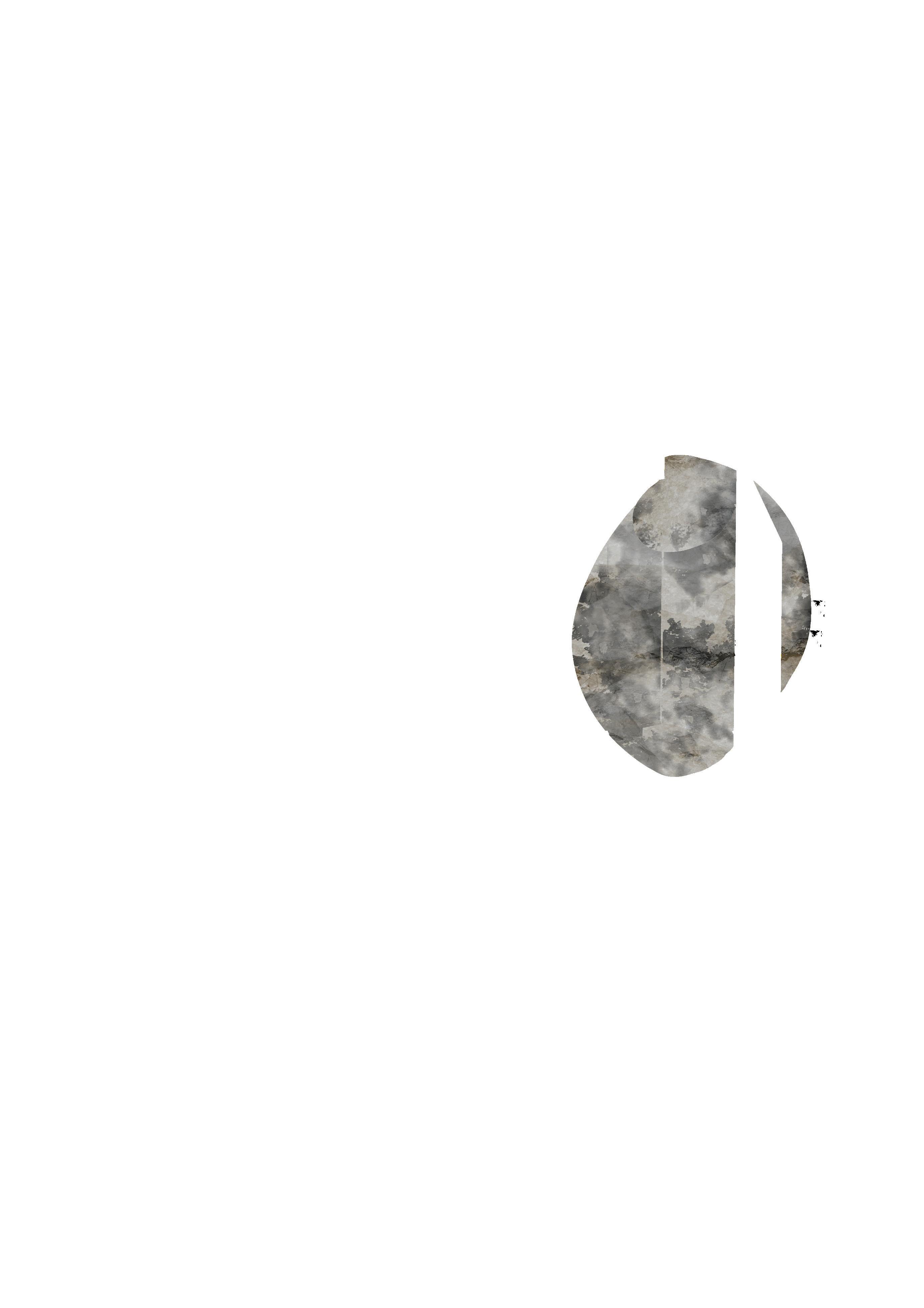
Something absent is something that is missing. What is missing cannot be deciphered or translated if the object is not identified, seen or present.
Thus, the absent must remain present within the vicinity performing as an anchoring point or trace of its absence elsewhere.
If two geometrical opposites are used, one being present and the other absent, moments are hinted or highlighted through their juxtaposition, thus initiating association.
Association is activated with a direct inclination to imagine and experience the process of formation. The story of the building unfolds itself through the desire to decipher and make sense of its components.
The presence of absence is determined by rather than just a 3-dimensional form, it adds a new element of experience. It surpasses the limits of three dimensions thus gains a sense of meaning which can only be understood when the architecture is experienced.
This project will be constructed seasonally in a region that is suitably cold for 3 months a year. Using hot and cold weather to its advantage to create a self-demoulding formwork through the use of ice, that leaves its negative trace behind.
The voids created due to the formwork amplifies this immensity of absence and presence to allow for one to place themselves outside this 3-dimensional realm of traditional architecture. It transcends the present as the geometry is once again shaped with immeasurable water pressure and gravity encased and restrained by the once arranged voxels.
I aim to achieve this through the design, investigation and exploration of a formwork that will allow the casted elements to capture, seize, and embody the history of its construction and composition making it progressively evident to the naked eye as one uncovers the space.
Design Statement
The project aims to design a civic centre. Fabricated throughout the seasons of the year utilising Cold and Warm periods as means of moulding and demoulding.
A series of shells will be casted through the use of a deployable hybrid formwork composed of 3 main components: The core, the vessel and the voxels
A play of opposition between traces of presence and absence, positives and negatives, will unfold the story of its construction and establish the language of the project at multiple scales.
In order to generate this formwork, I will explore materials suitable for the core, flexible formwork to enclose that core, scheme a set of voxels that will shape the initial two components on site, and lastly develop the technique for casting the shells onto it.
Technical Statement
The project is technically investigated through a series of experiments, observations and analyses leadings to formation of expressive architectural shells; I will explore wether the forces put in play can be manipulated enough through formwork.
I will be understanding:
- The formation of the core, the different states of water, required Environmental conditions and evacuation of that water.
- The behaviour, materiality and manufacturing of a flexible formwork that will bear excessive pressures, compressions and gravities.
-The interlocking of a set of reconfigurable voxels to function at diverse scales
-The application of concrete in such conditions
Through the use of weather, formwork and technique the design of the project will evolve. Rather than being read as just a 3-dimensional space, the element of experience will be considered and enhanced through the supplement of a presence of absence.
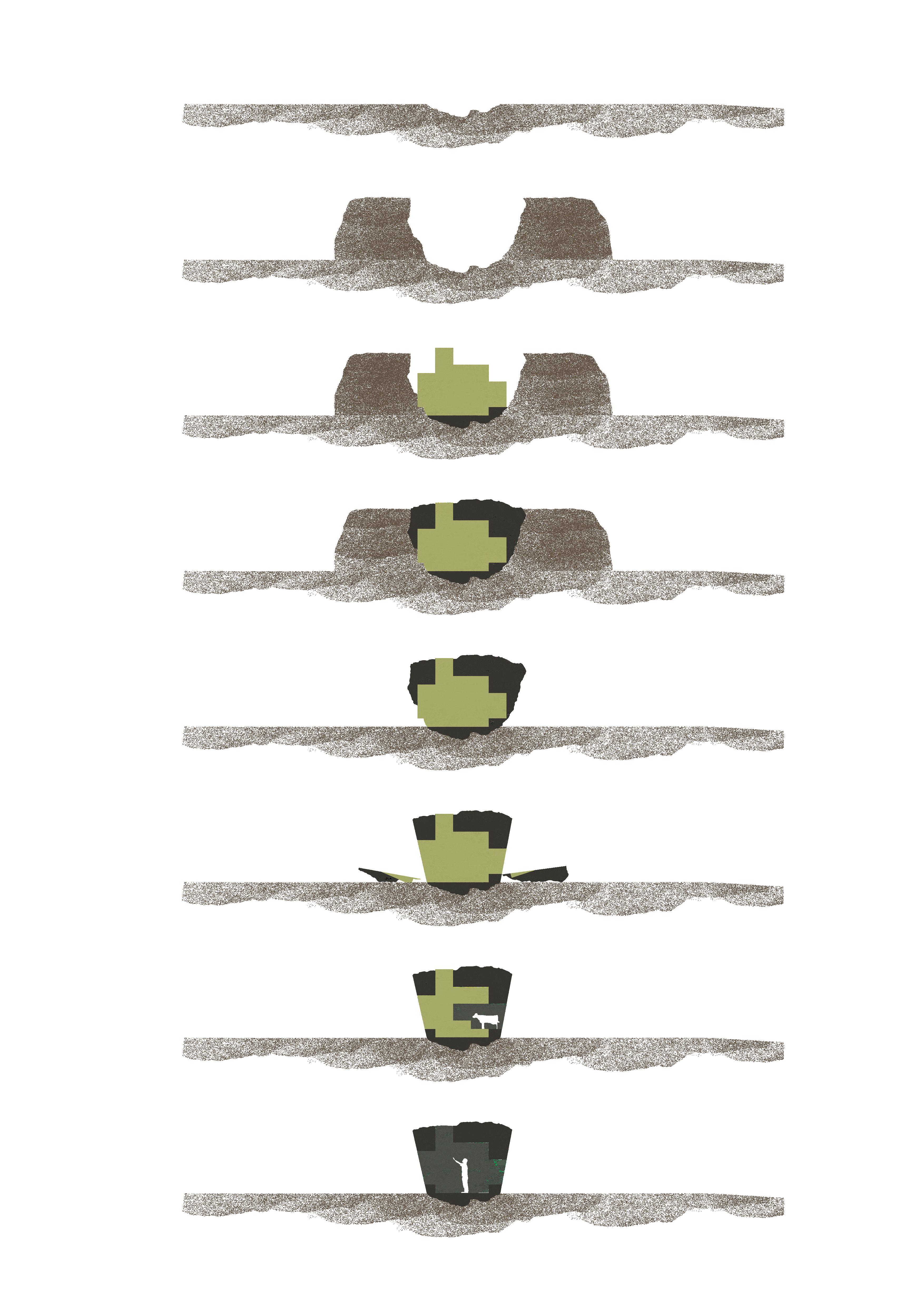
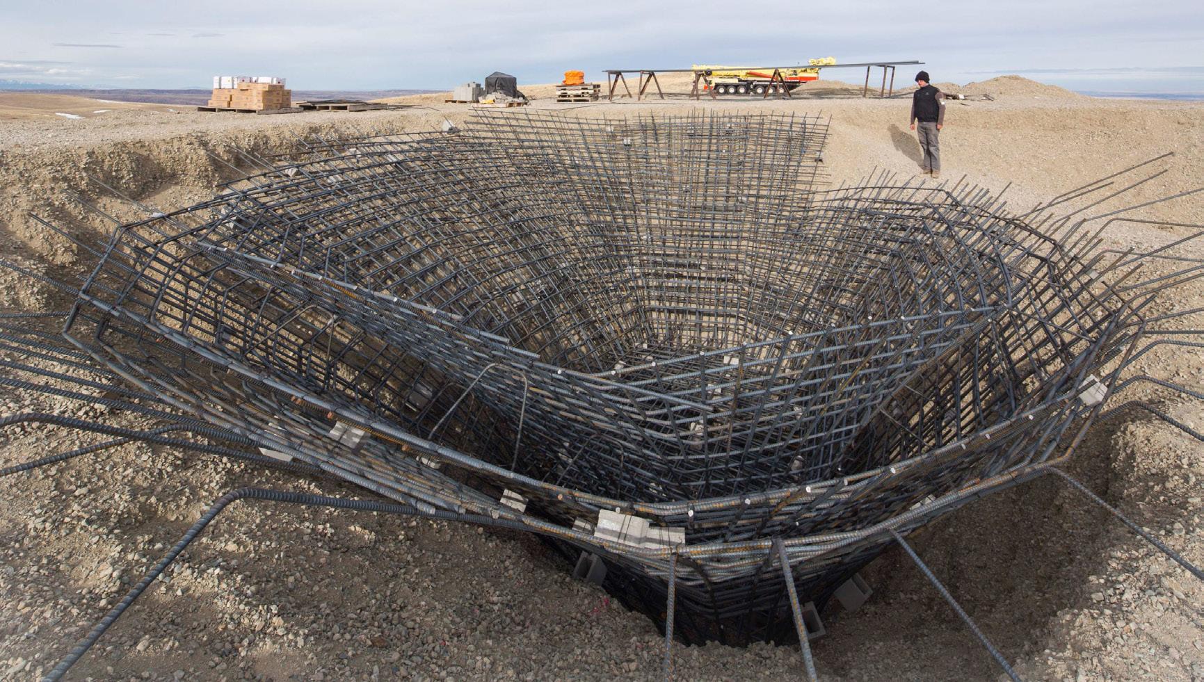
Construction Sequence 1
A series of technical studies result in the construction of a concrete shell using pre-manufactured formwork brought to site in a container and the use of water collected in a lake located at the epicentre of the project to be reused to cast different shells every winter season.


Ice core
After a few weeks, the ice core is formed and the solid formwork is ready for casting.
PVC Membrane
The shape of the membrane is fixed now that the ice core is formed, modules are demolded and their imprints remain.
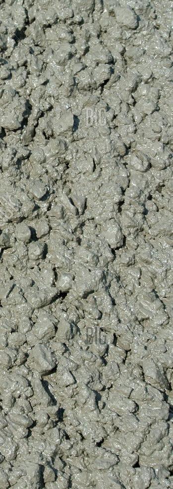
Concrete Layering
A series of thin layers of HPC concrete with ad mixtures are sprayed onto the shell surface; once that layer hardens the folowing thick layers of concrete can be applied indepentently of the ice core.
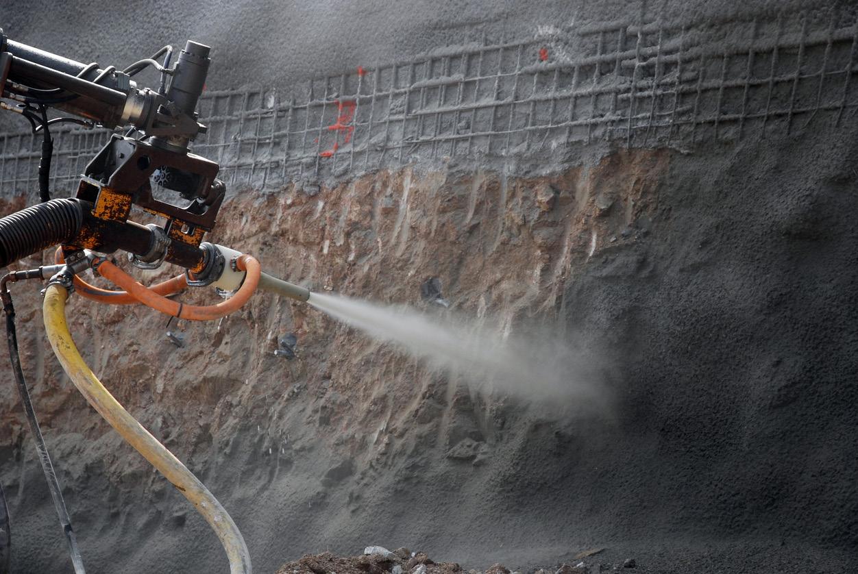
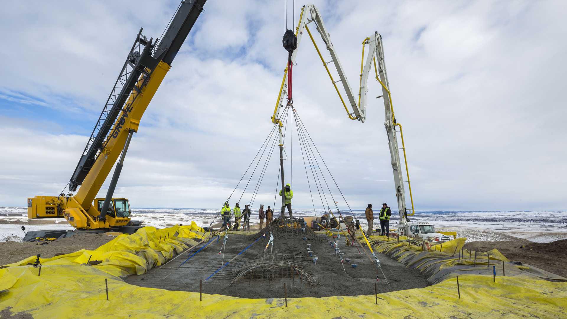
Shotcrete application
The concrete is pneumatically projected at a high velocity onto the formwork via a robotic movable shotcrete machine.
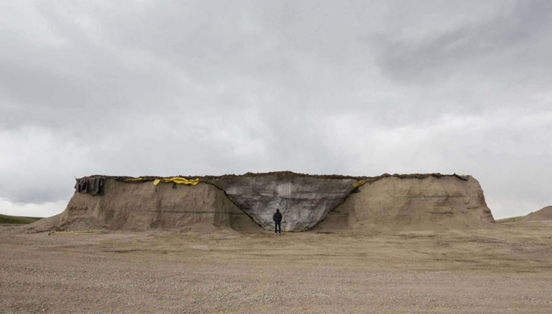
Water drainage
Once the concrete has set and the winter season is over the ice core will melt naturally and self demold, draining back to the lake to be reused for the construction of a next shell.
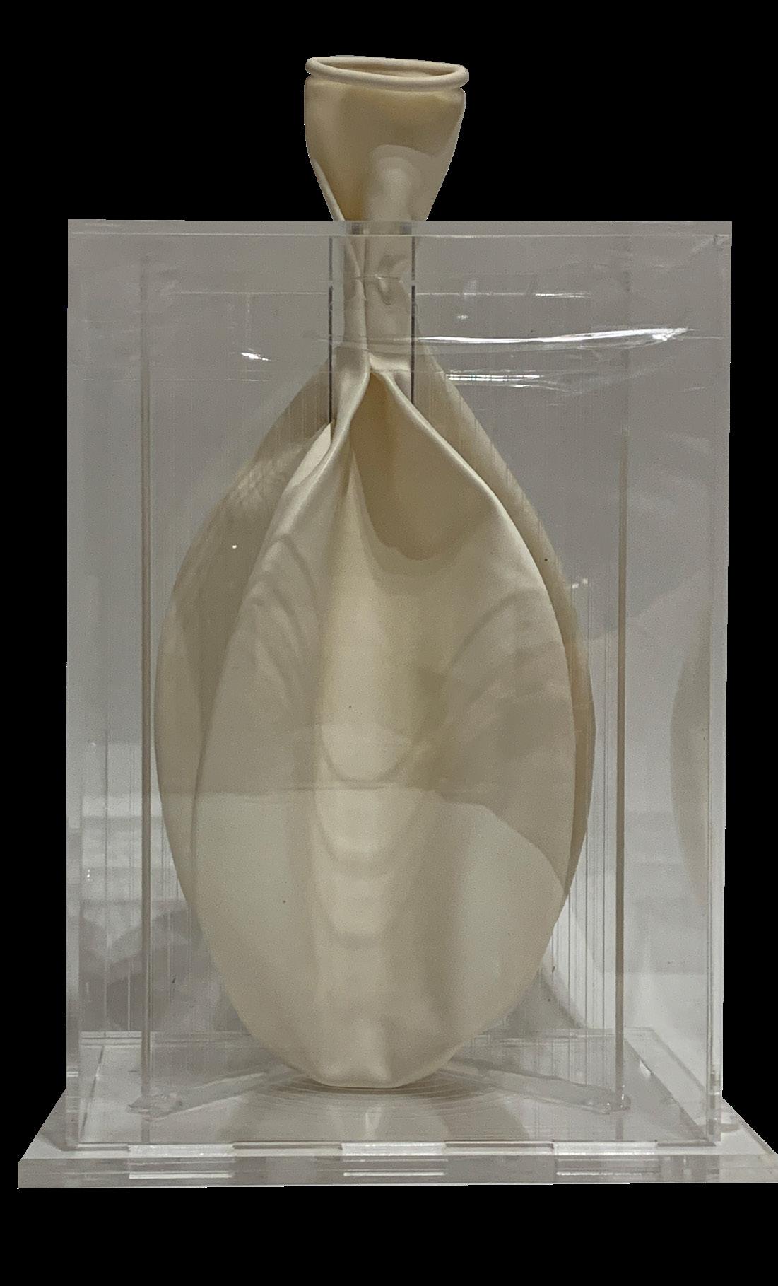
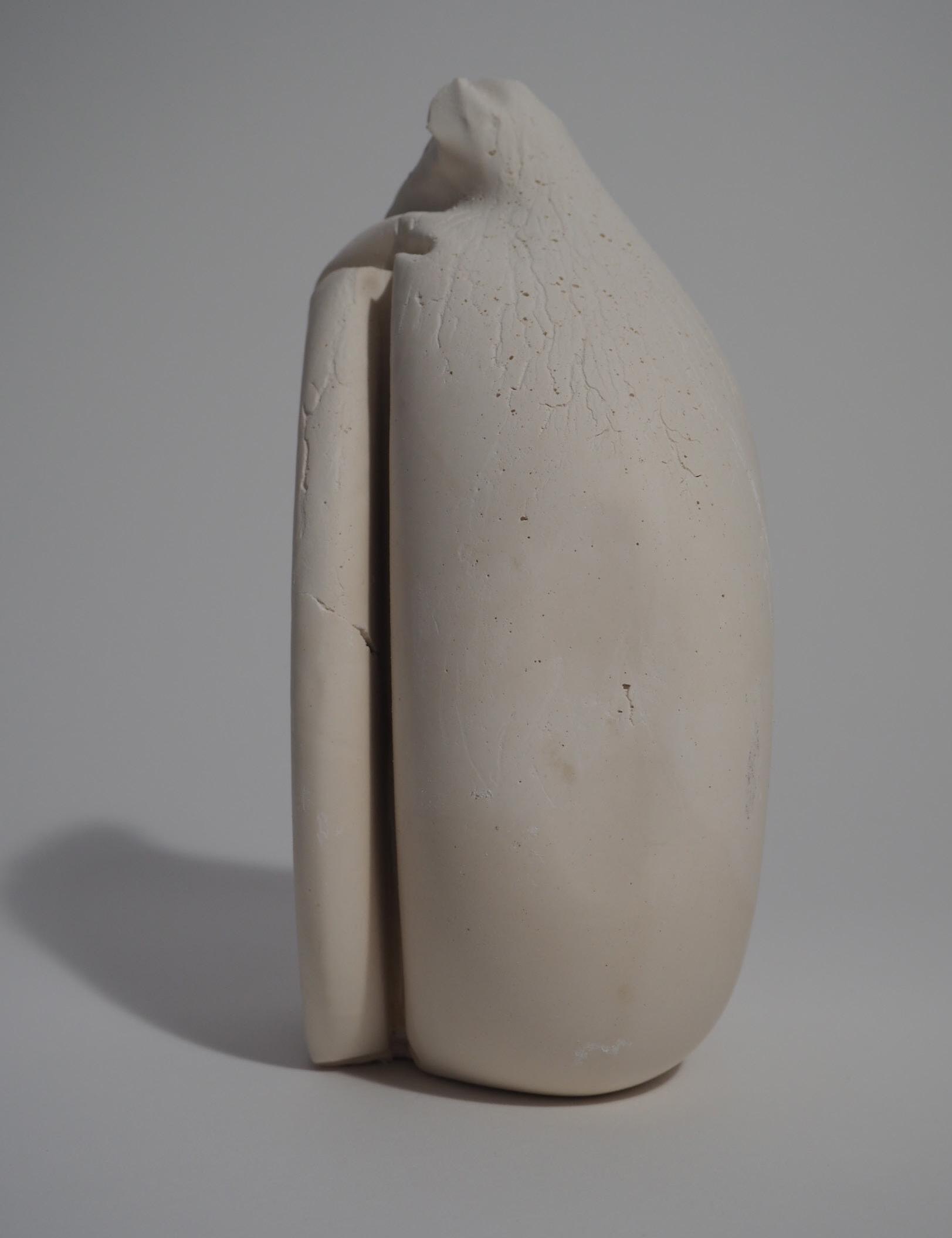
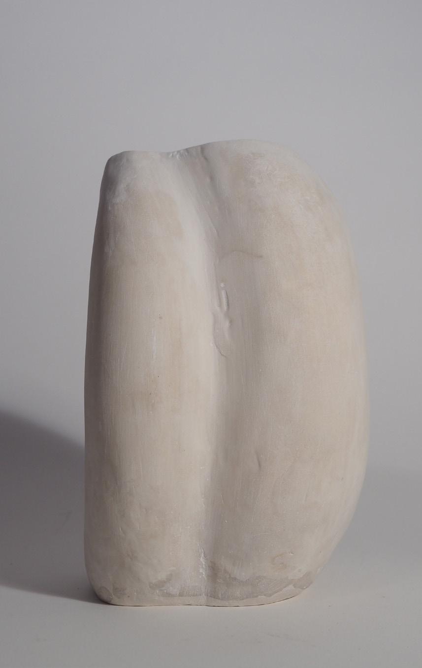
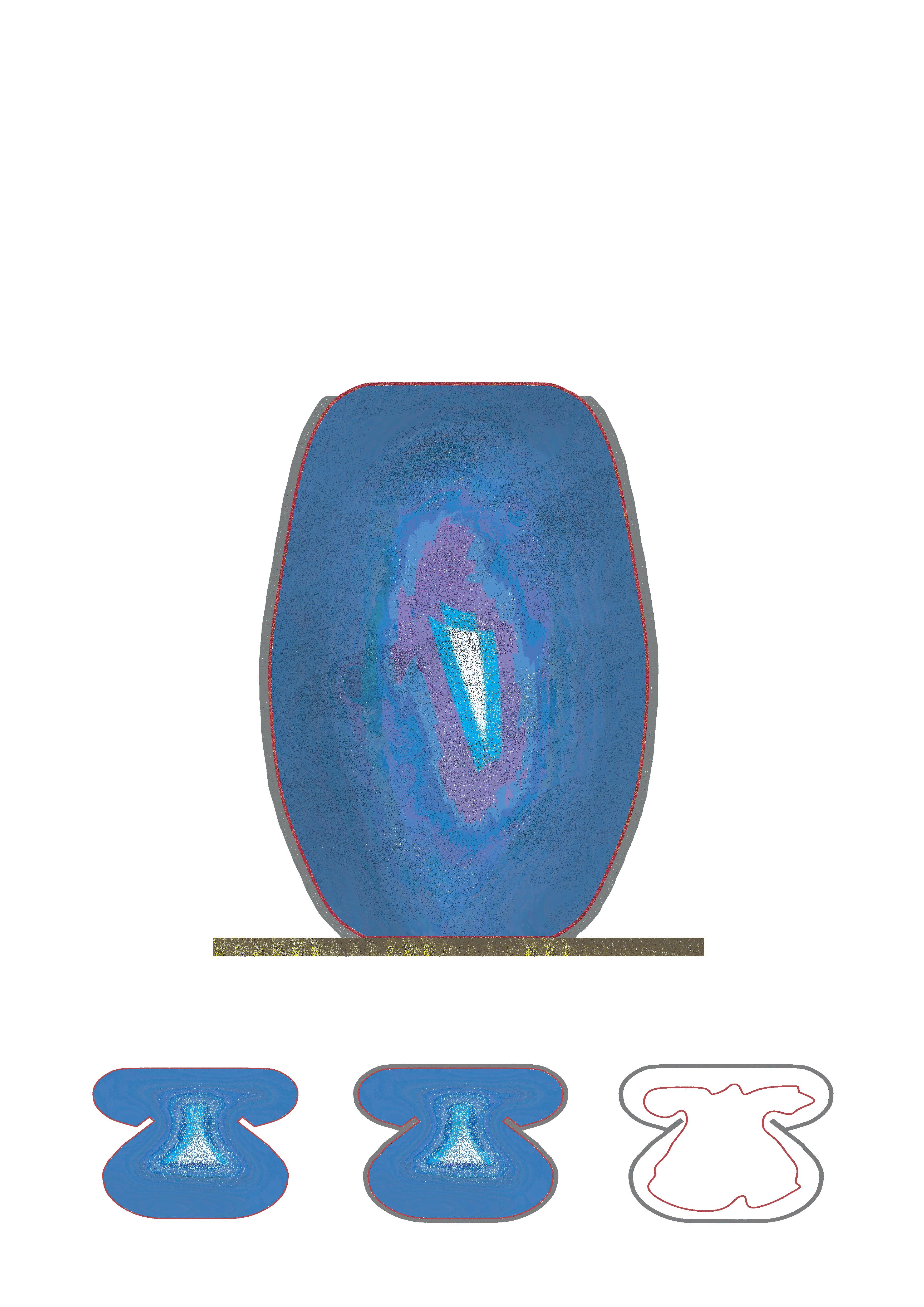
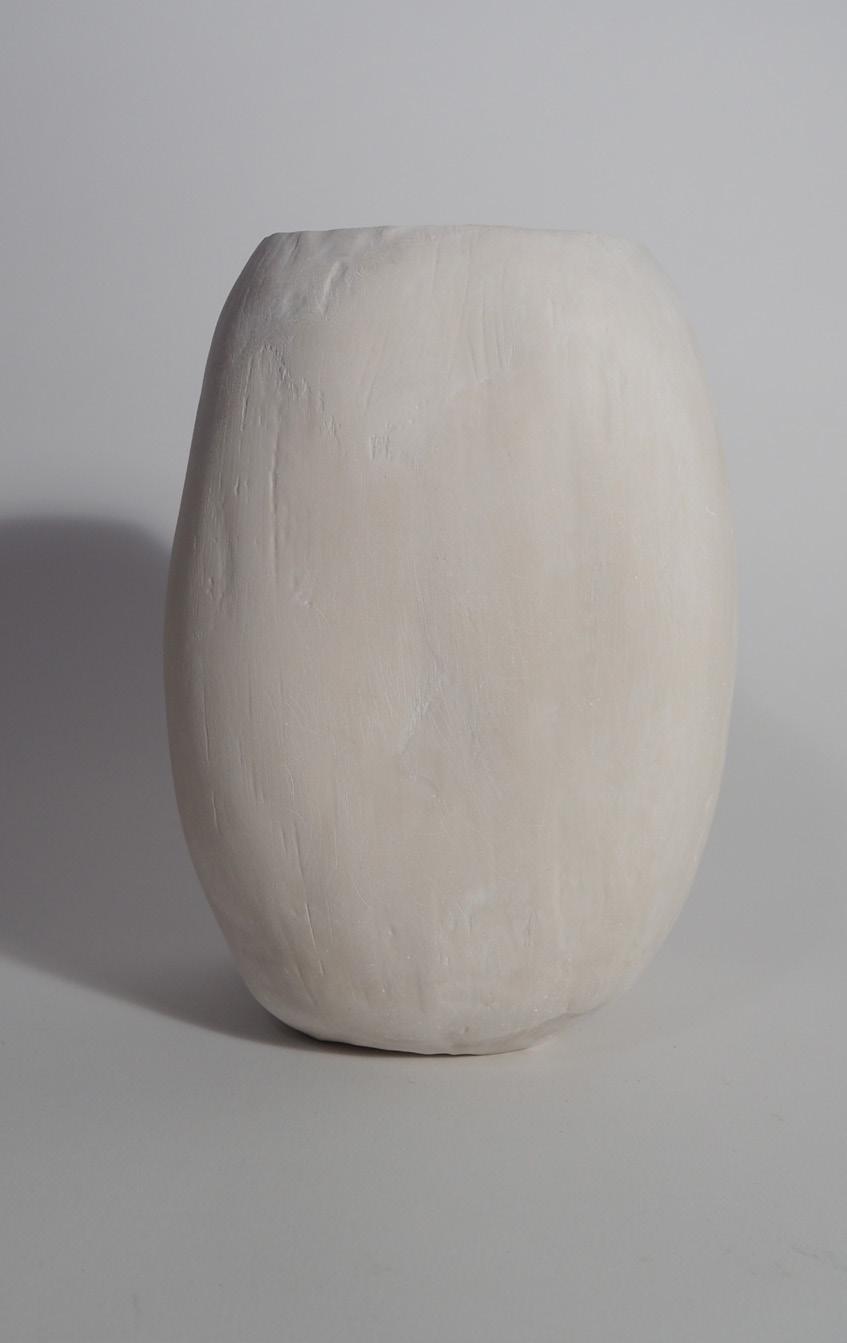
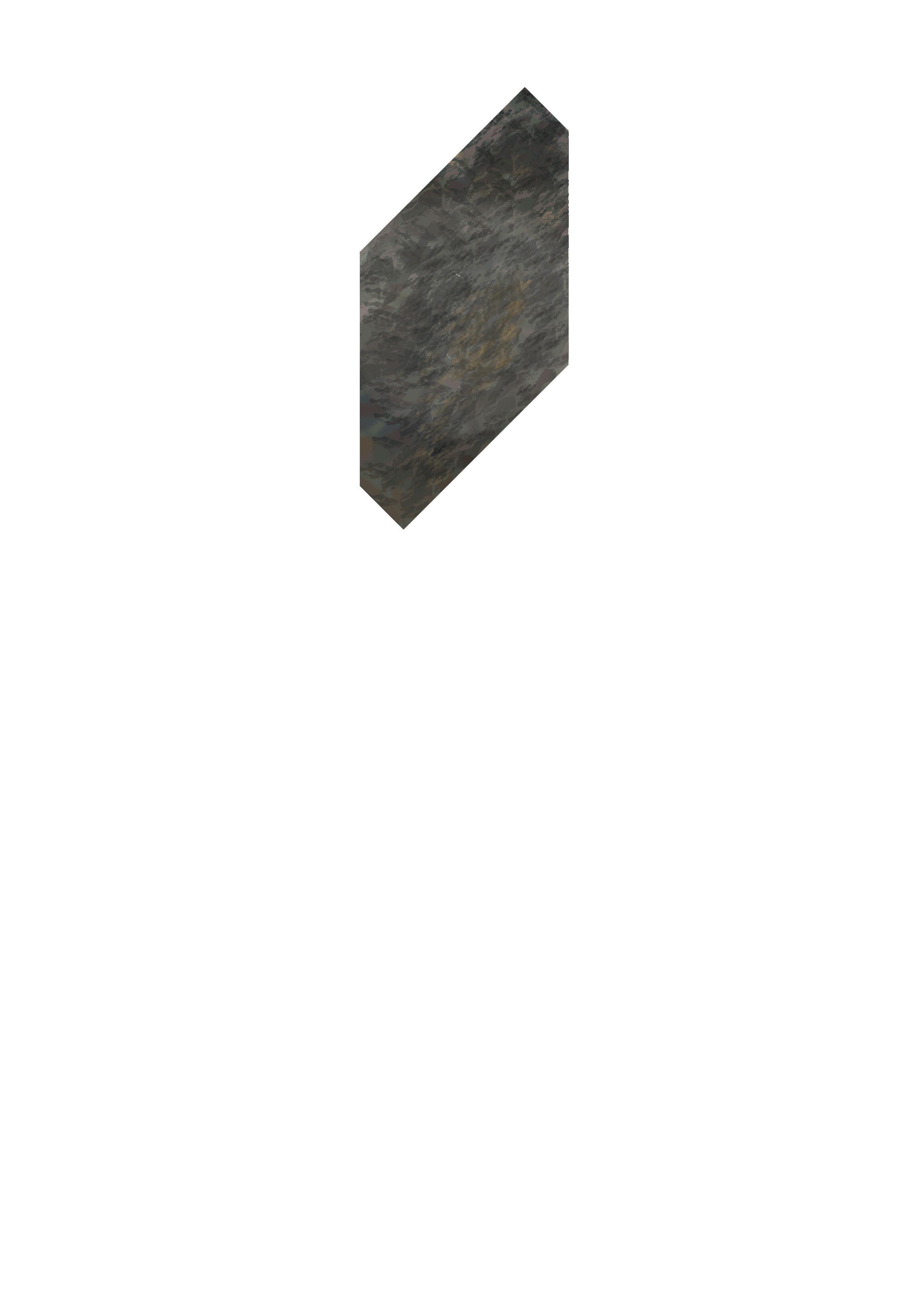
This first series of experiments explore the use of one simple free-from flexible water bladder and sharp xyz axis limited geometrical opposites can produce different outcomes depending on their placement.
Two elements are used:
- Flexible formwork that results in double curvature by nature (latex membrane)
1:2
- Hard straight edged falsework fixed to a base.
By using theses two opposites together, the resulting form shows the clear contrast of the two by capturing pressures tensions that occur during the casting process.

1:2
The placement of the Falsework dictates the end form that the initial spherical blader.
Sections
1:4
1:4 Sections
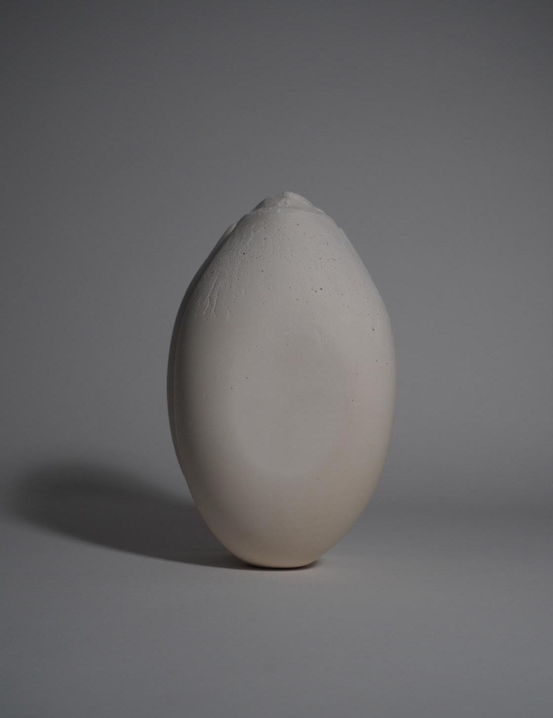


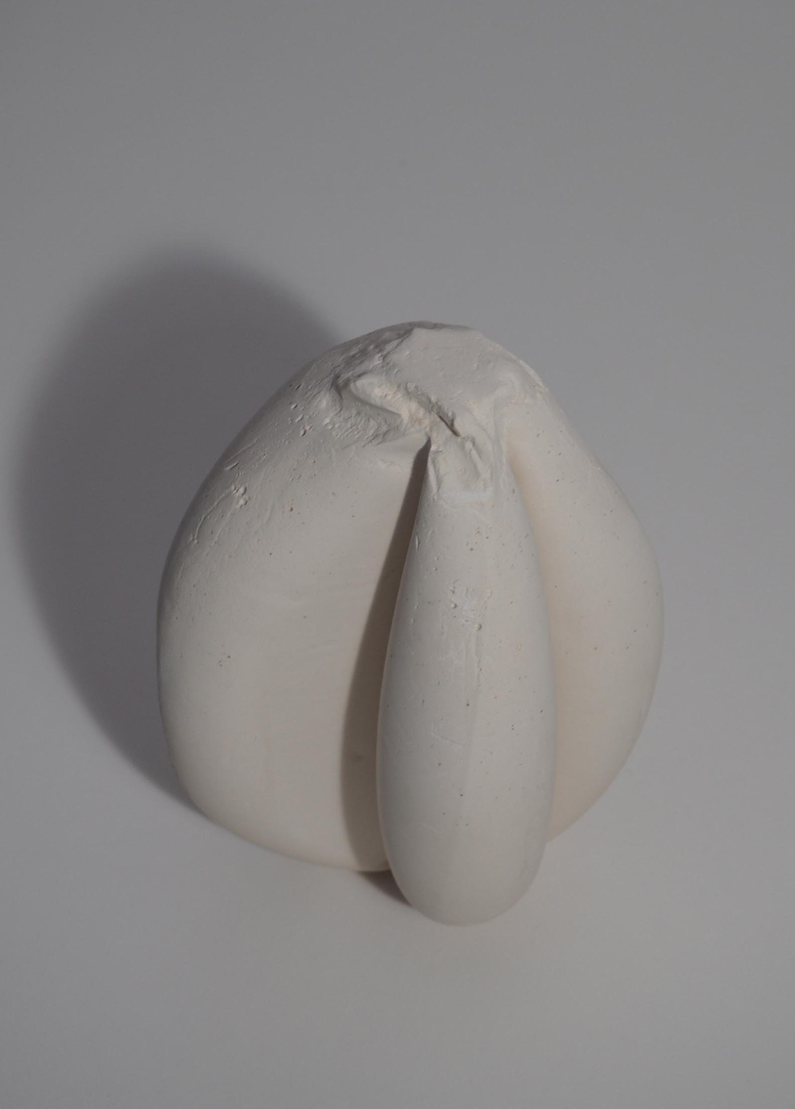
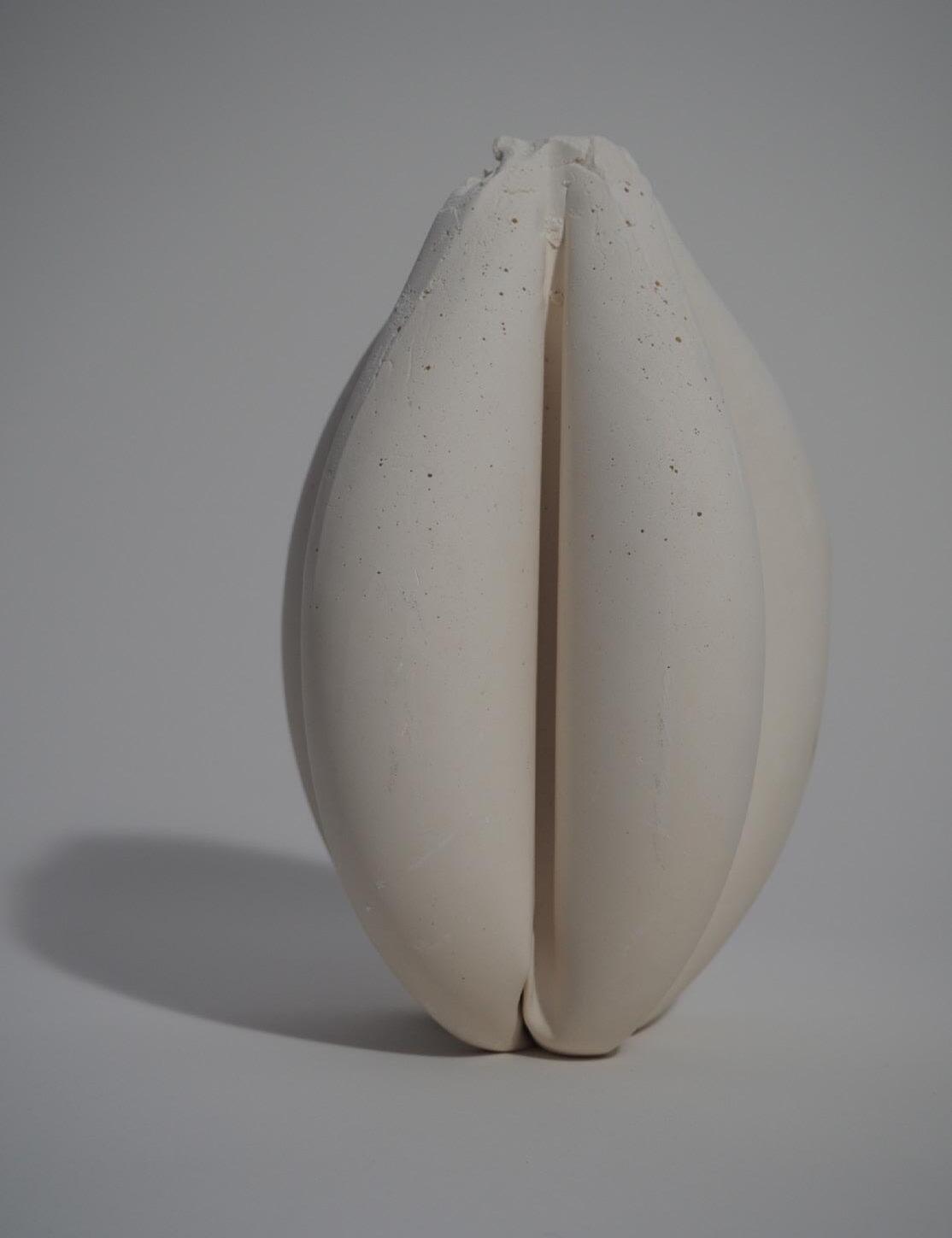
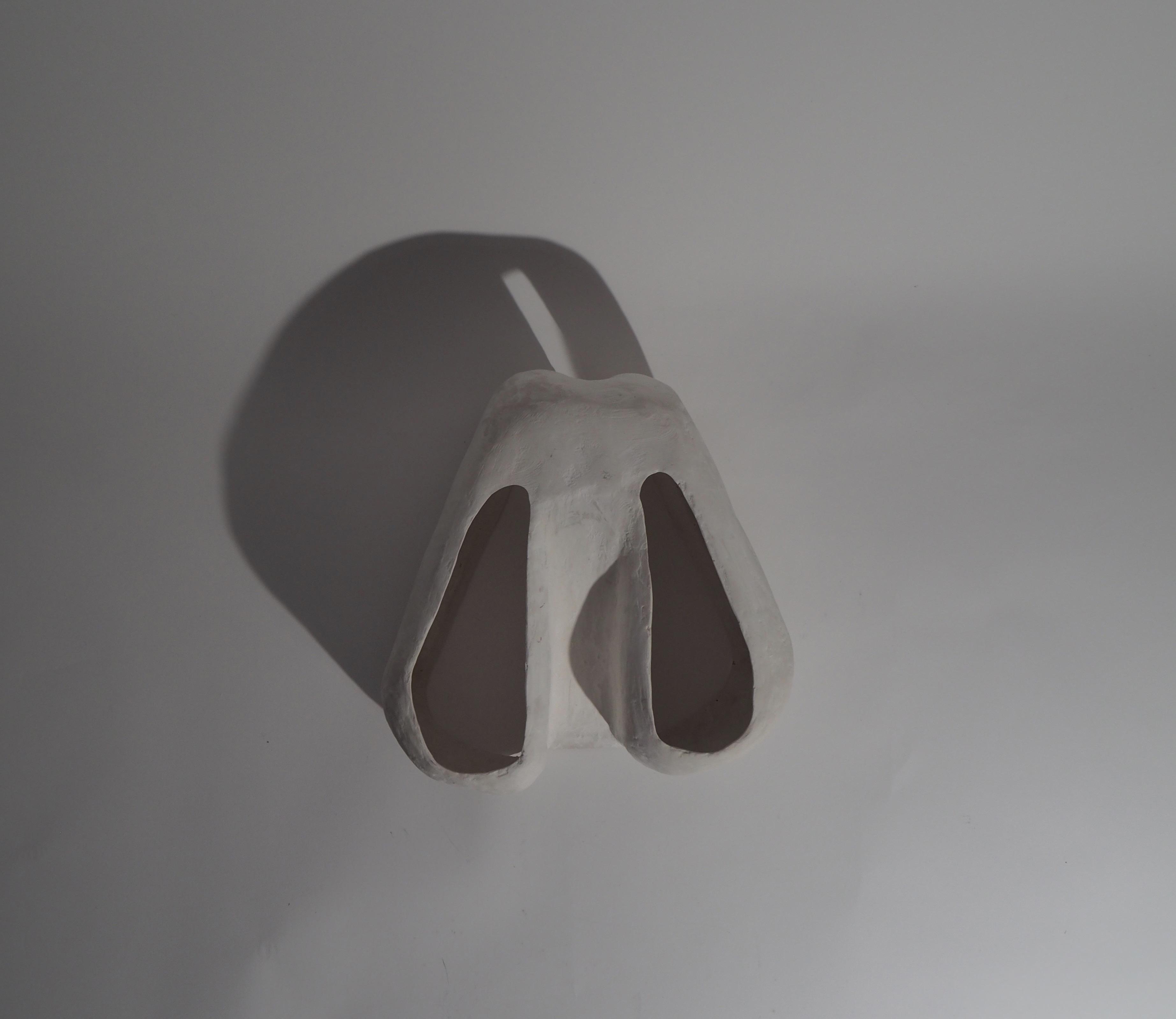
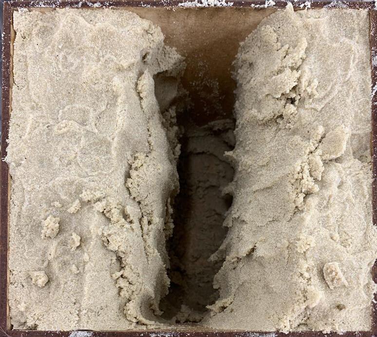
Different wall partition positioning within the same perspex box causes the blader to behave in a different way.
Due to the angles at which the walls were placed the liquid had nowhere to go but towards the bottom left and top right corners of the box coming in contact with the 2 largest faces leading it to also touch the two smallest faces of the bounding box.


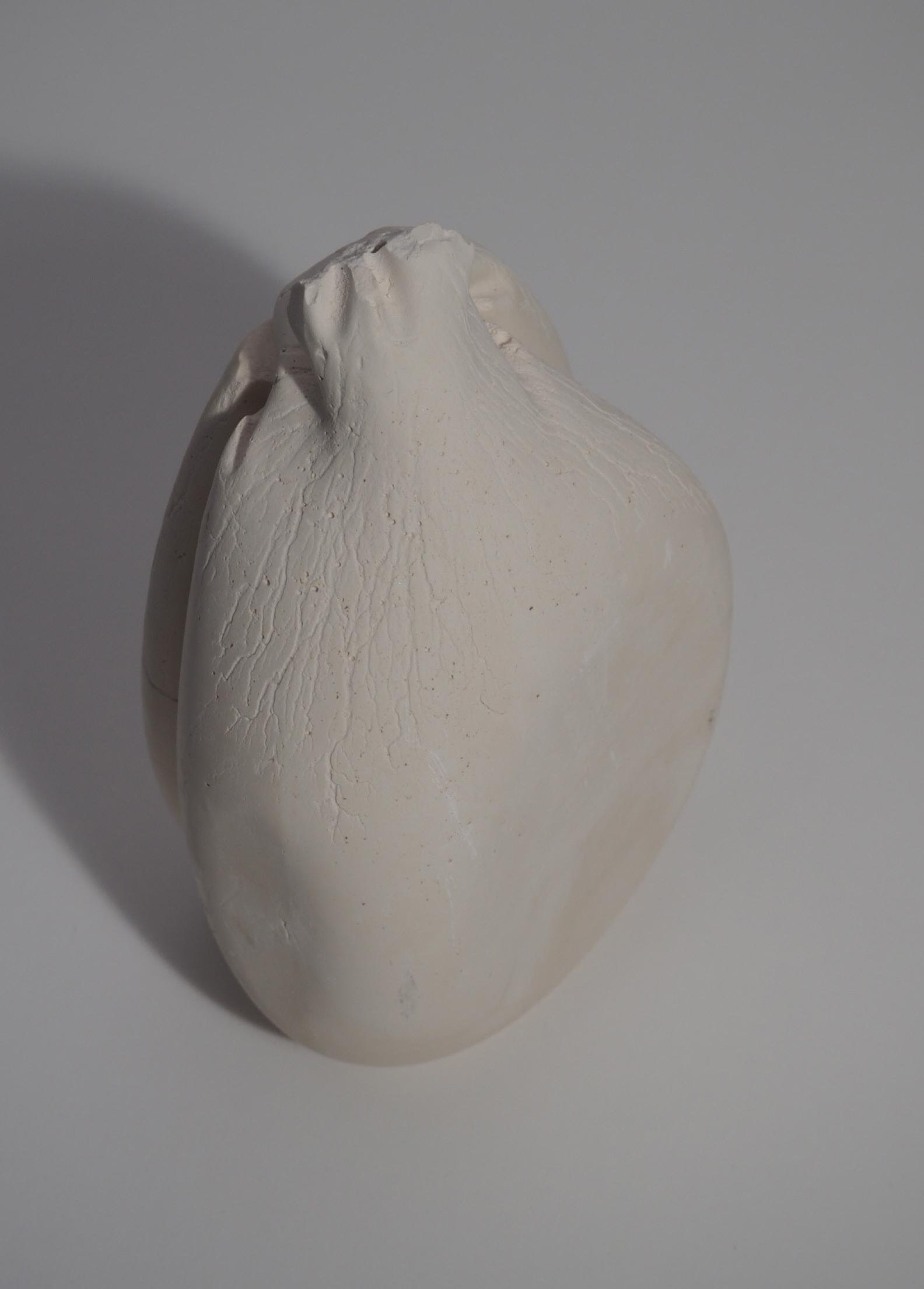
Observation: The liquid will not necessarily accumulate at the bottom due to gravity but will rather go where there is more give in fabric material.
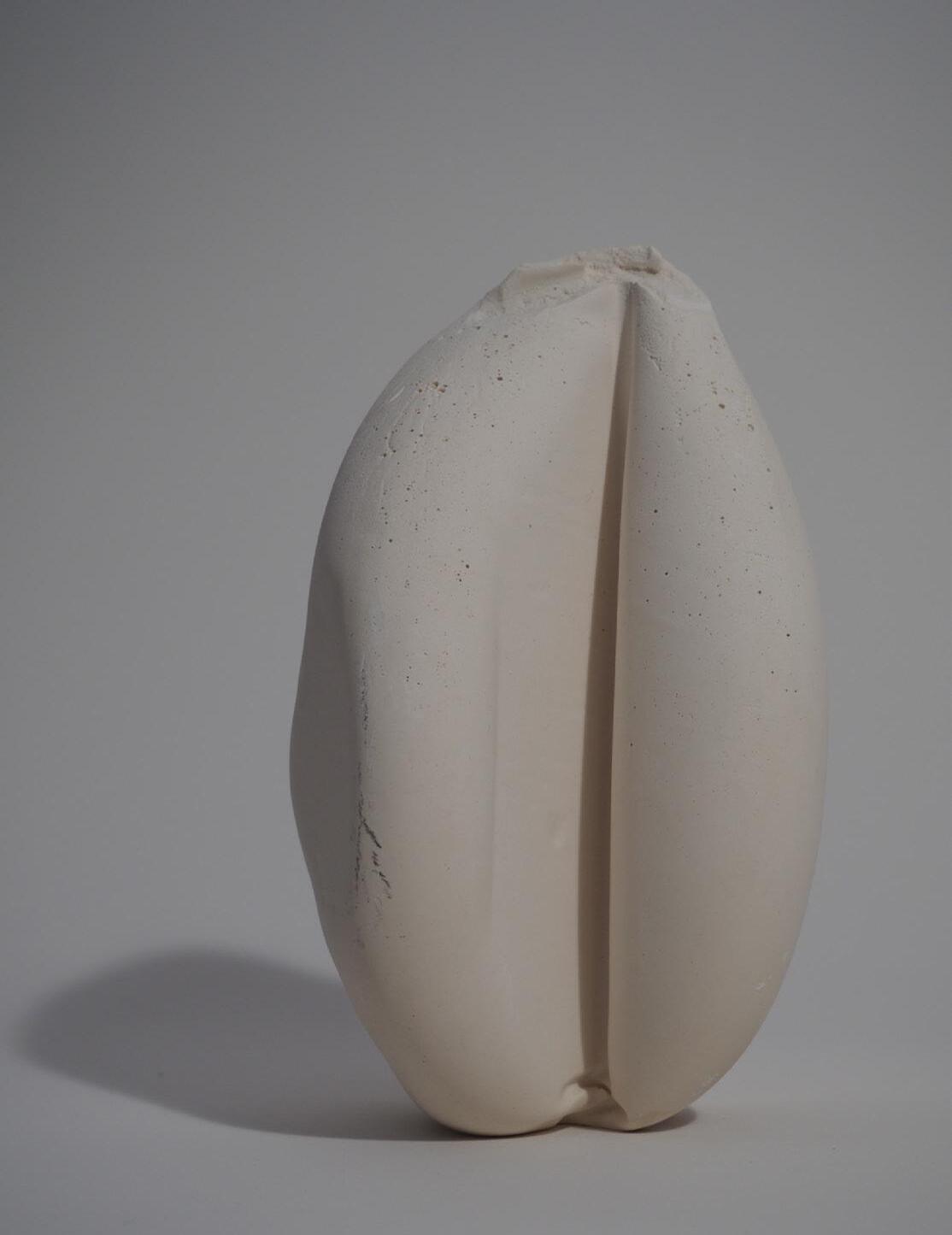
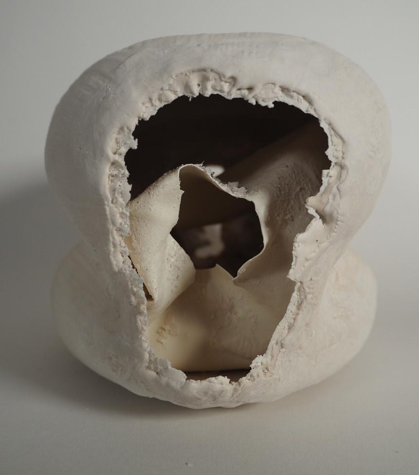
1:2 Axonometric Membrane Cast

With this 3 wall configuration, the liquid no expands the membrane in 3 direction and does not stretch all the way to a box face.
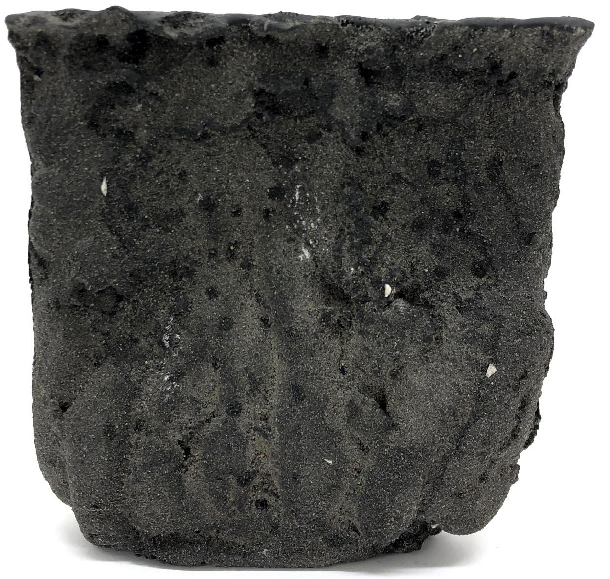
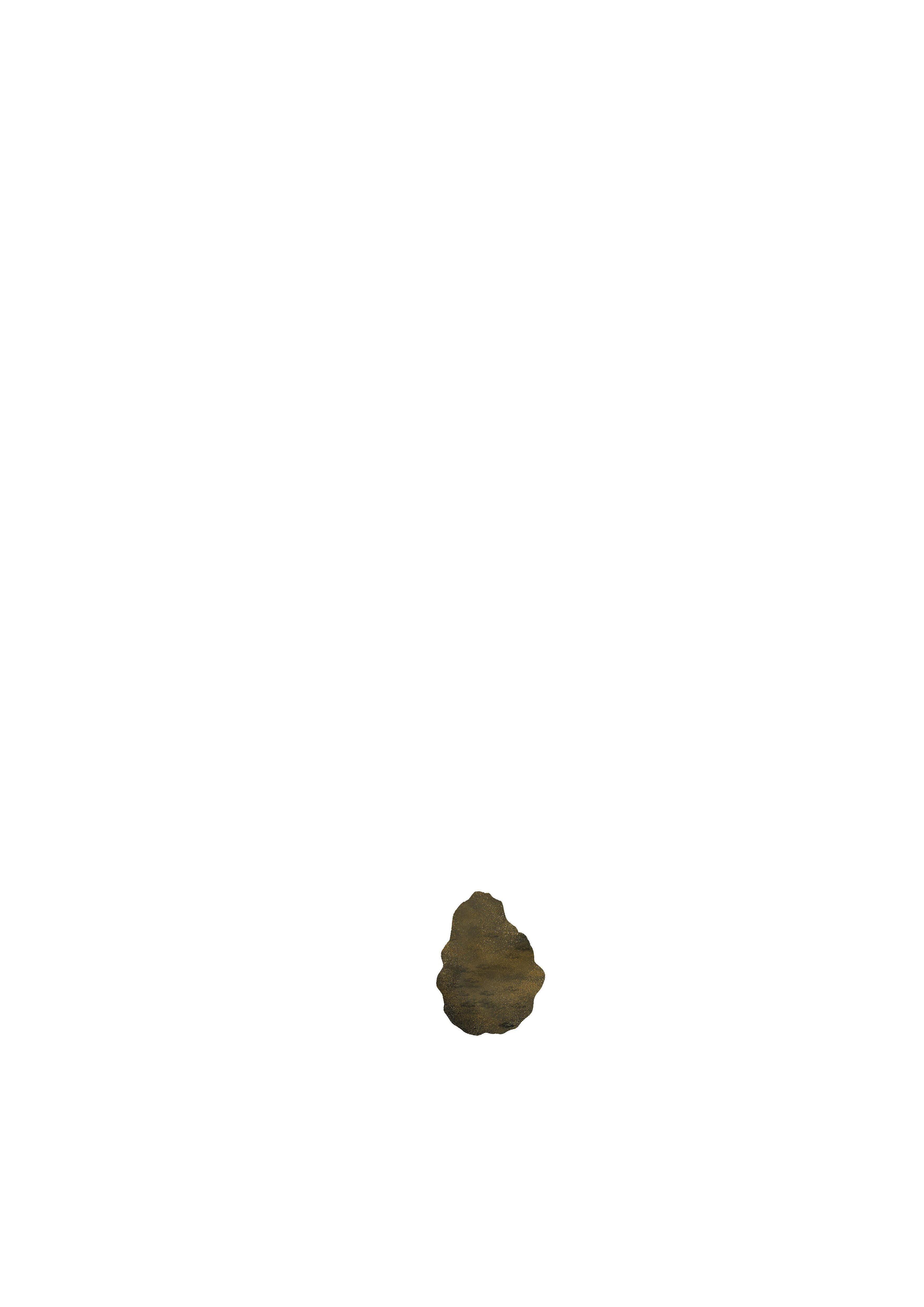
A small amount of non compressed wet sand was introduced into one corner and was then compacted by the membrane expansion modifying its form.
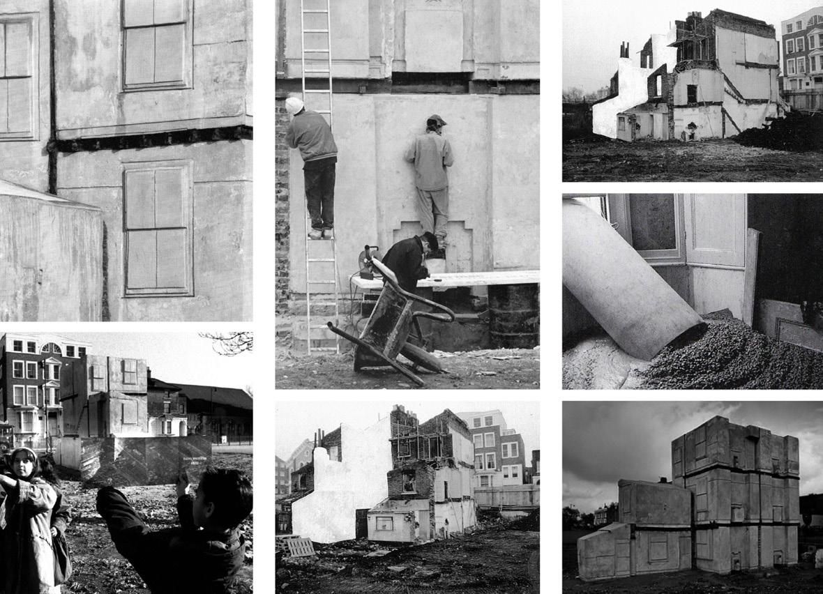
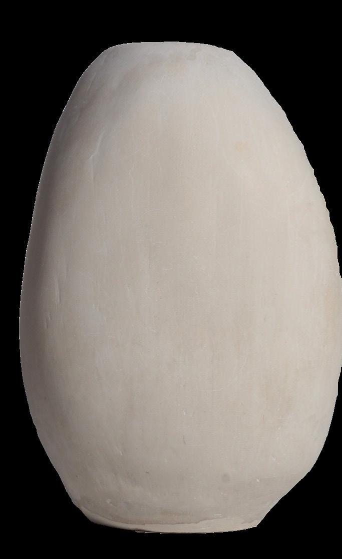
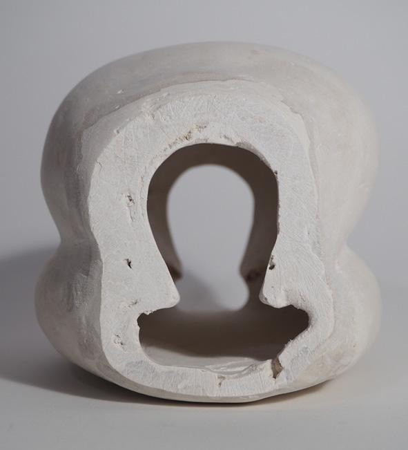
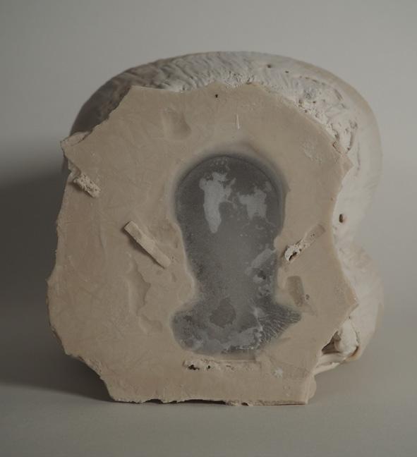
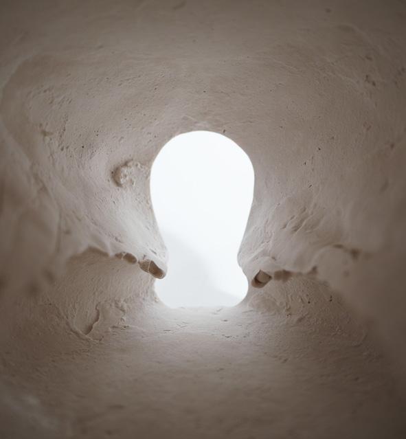
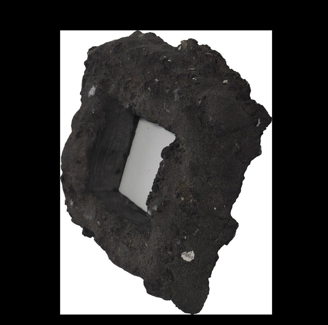
Rachel Whiteread uses industrial materials such as plaster, concrete, resin, rubber and metal to cast everyday objects and architectural spaces.
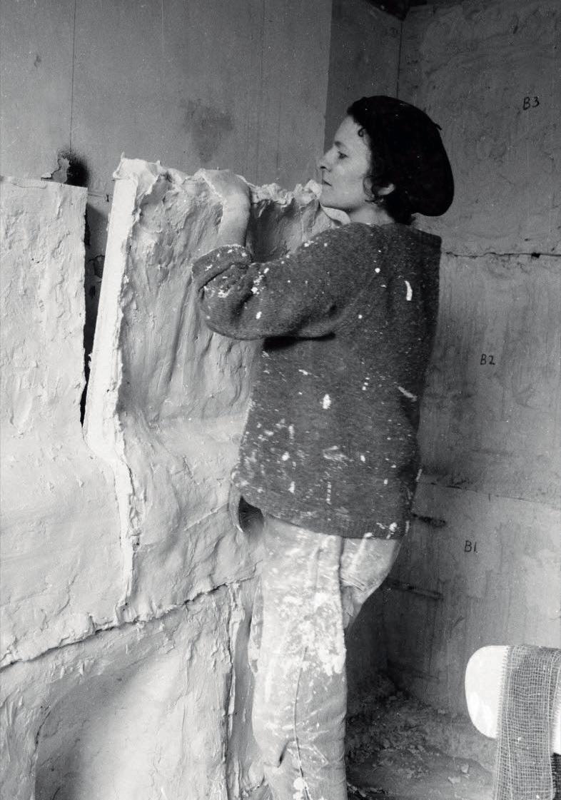
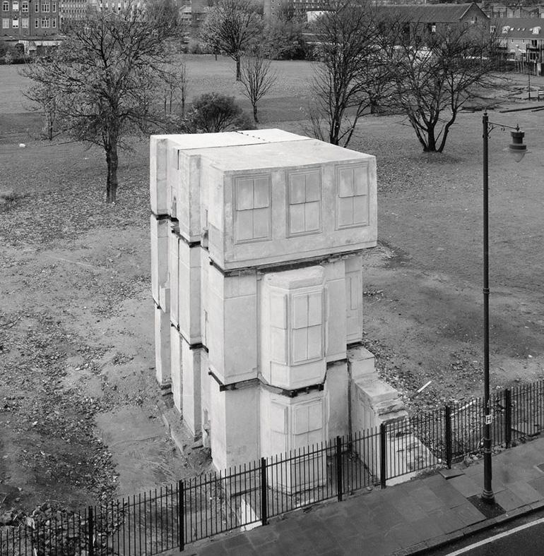
The buildings are not simply fully casted as if they are the formwork in themselves but they are more like falswork.
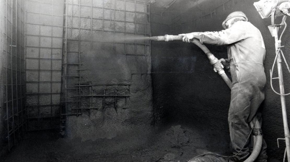
A separating layer is applied to the inner walls of the building (Fig 1) and construction works enter and shotcrete the building from within creating several layers and adding rebar reinforcement for structure. (Fig 2)
The building is then demolished from the outside (Fig 3) and the casted inner spaces remain solidified, frozen in time. (Fig 4)
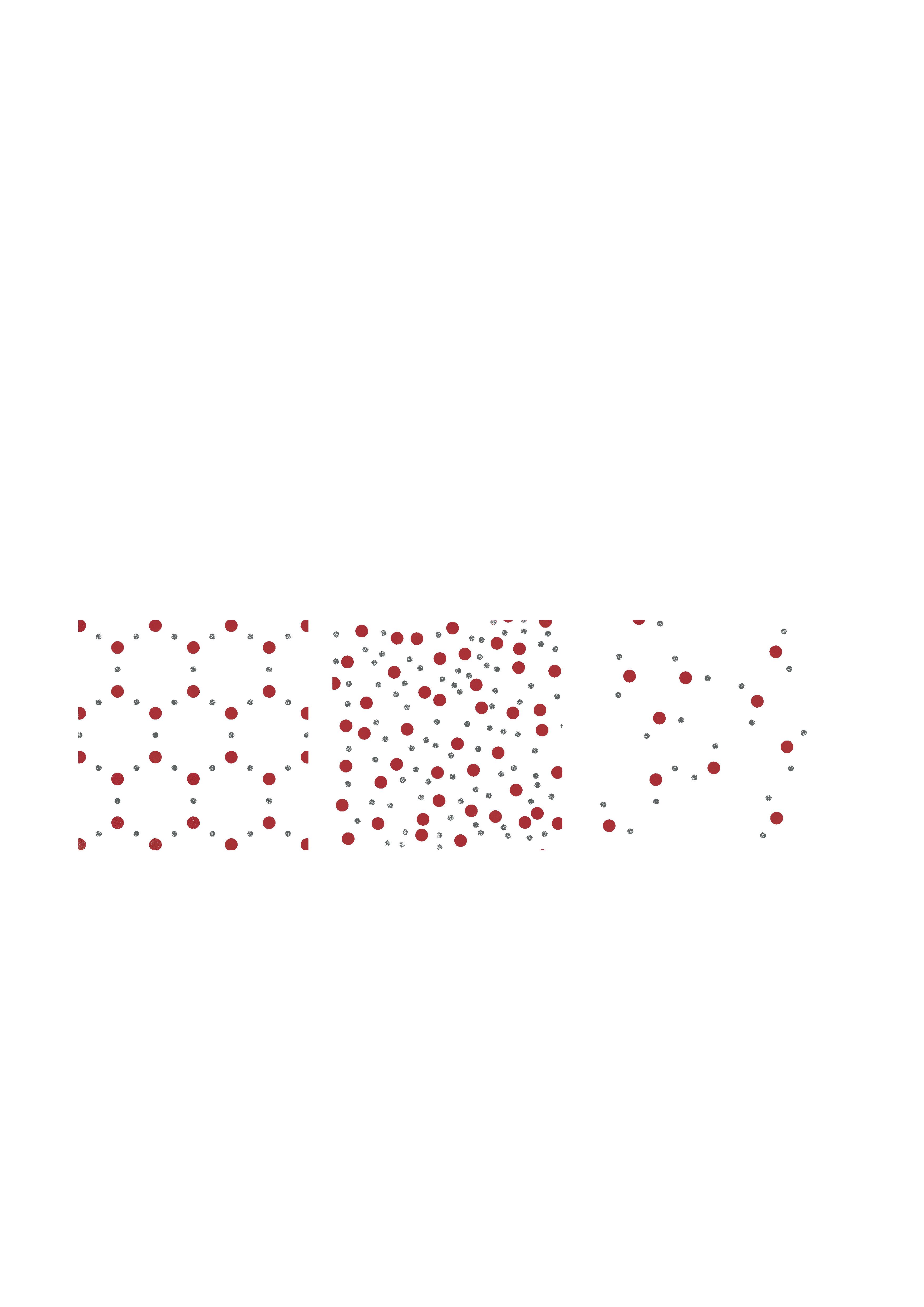
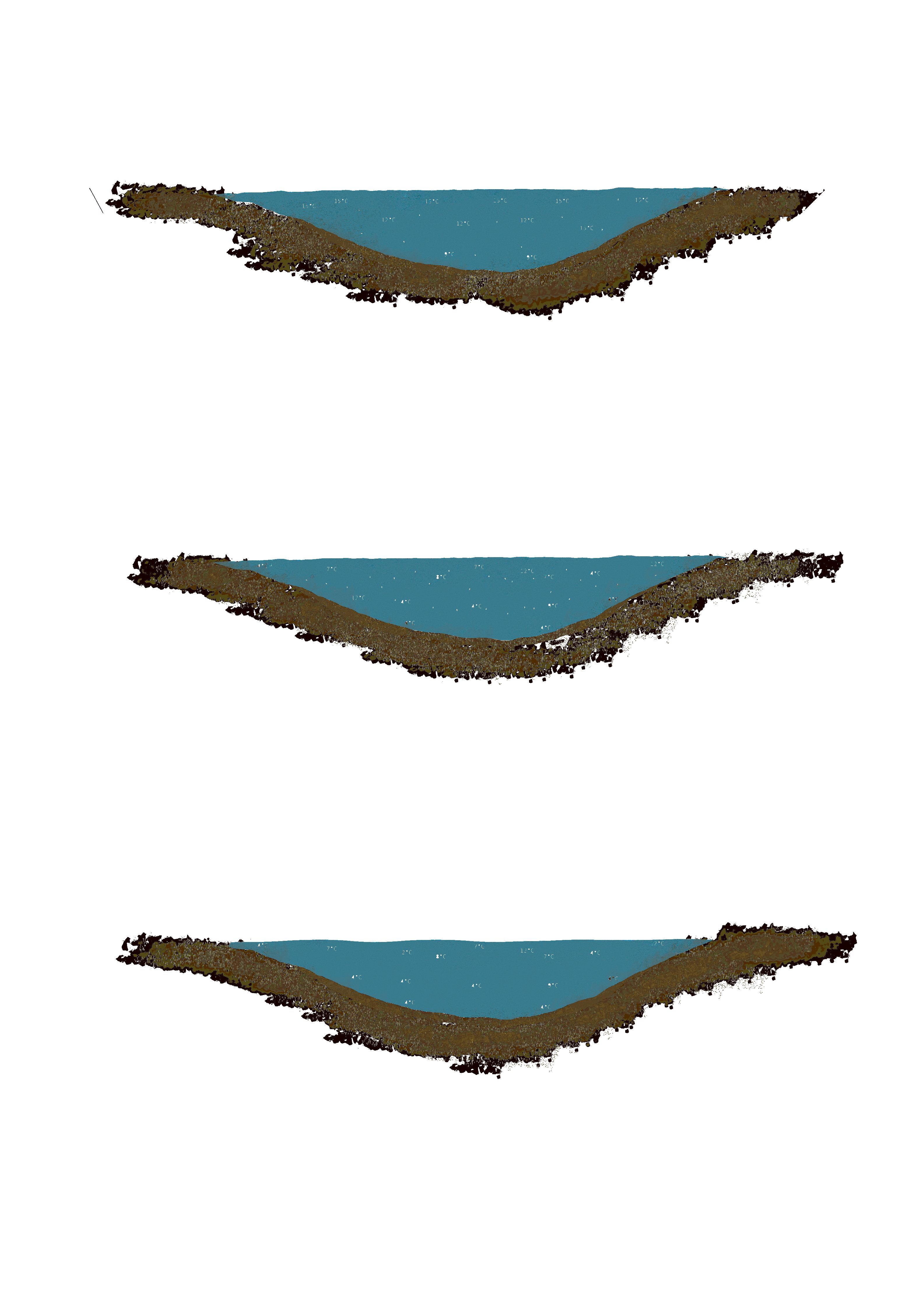
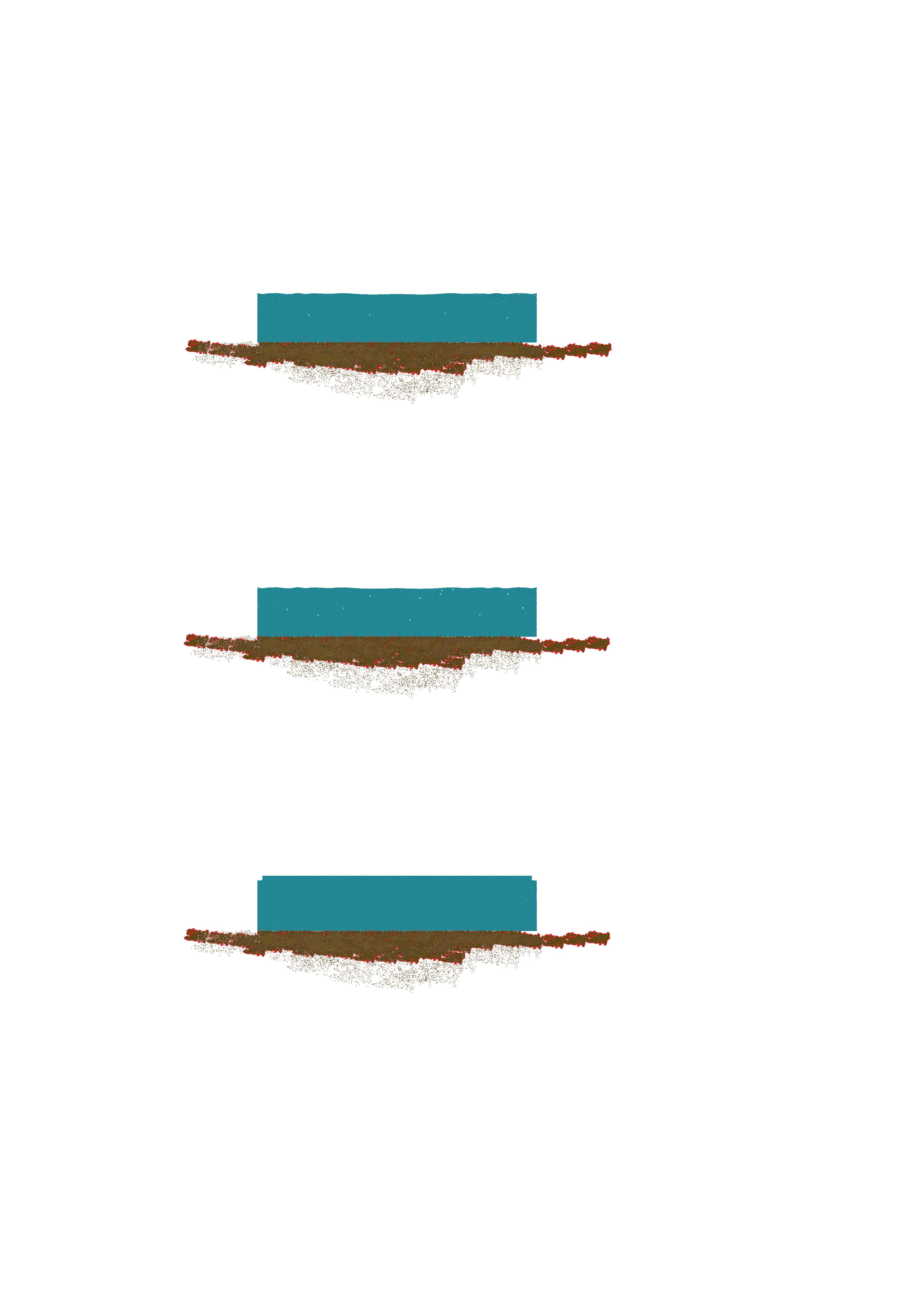
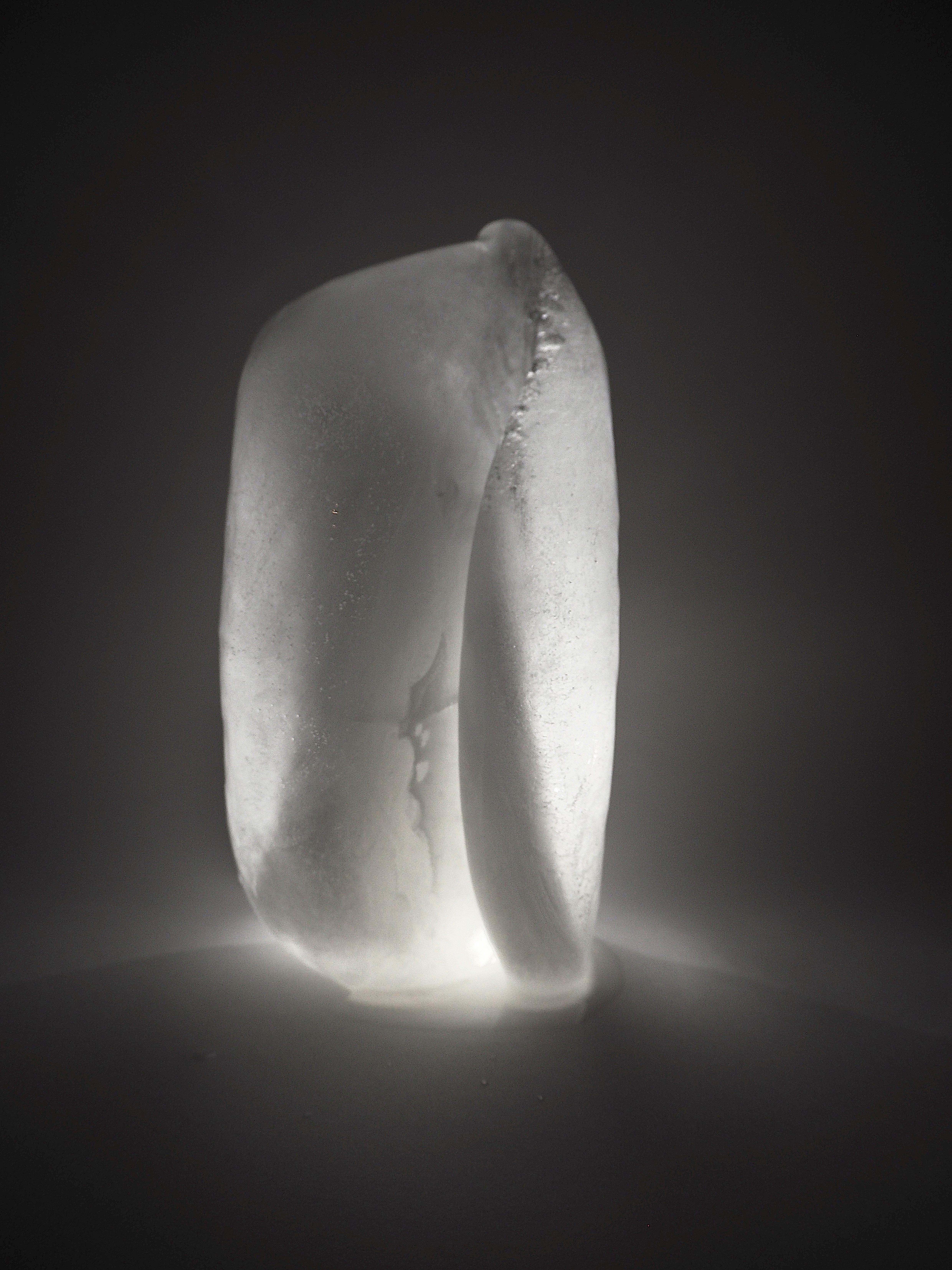
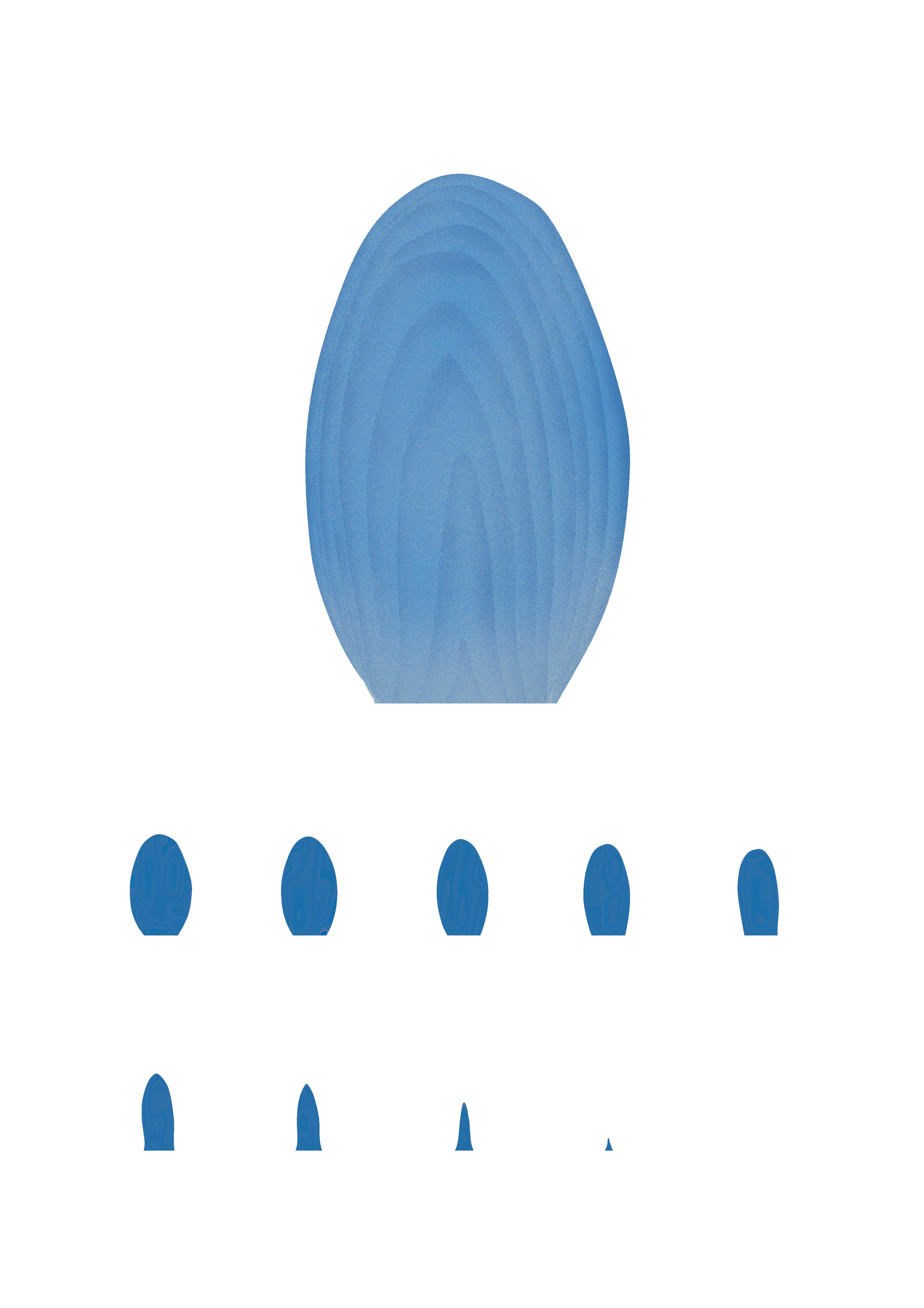
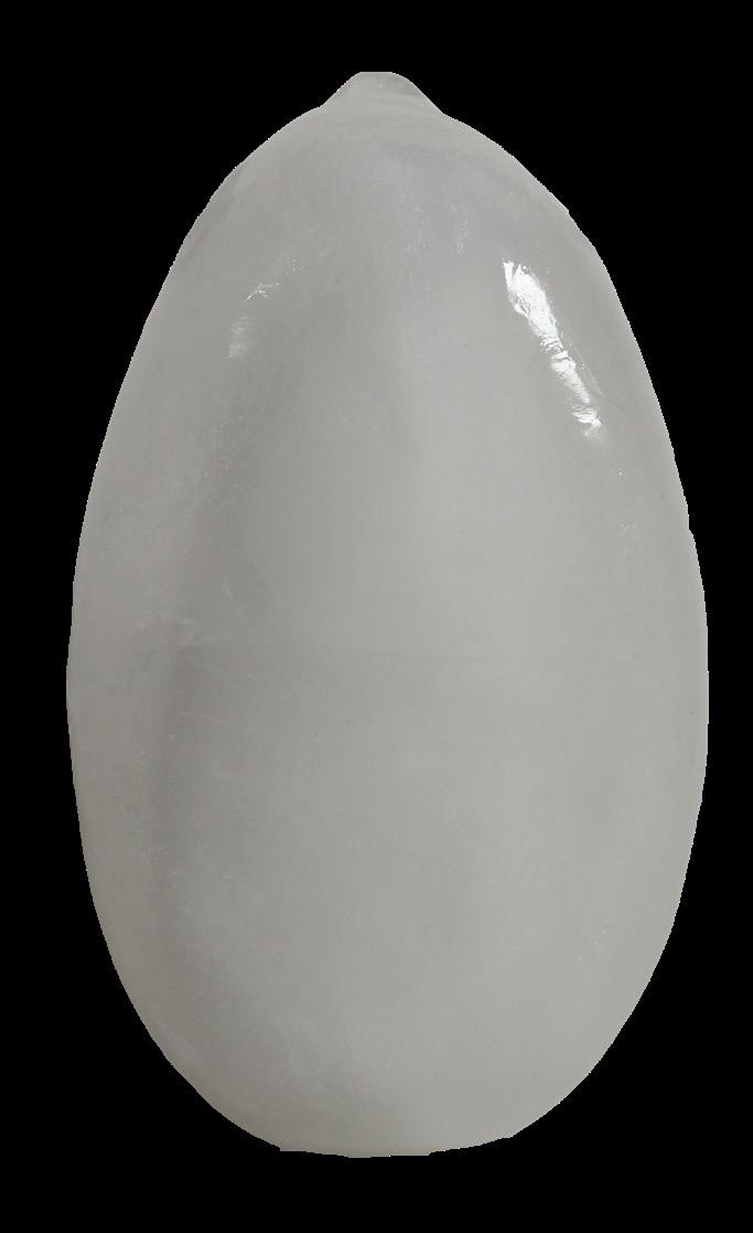
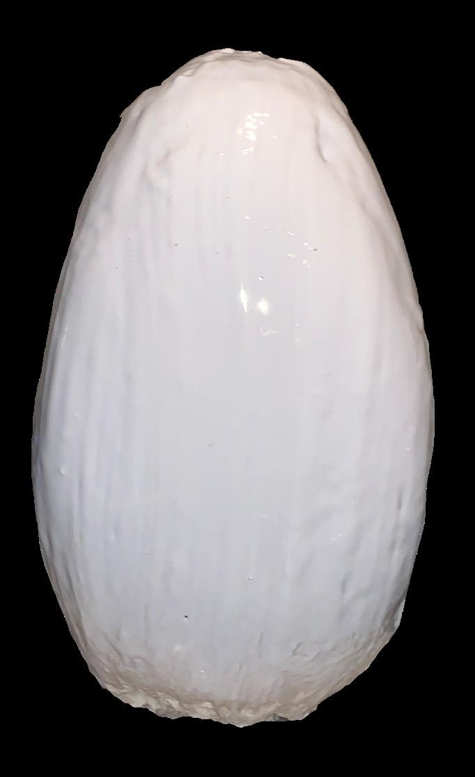
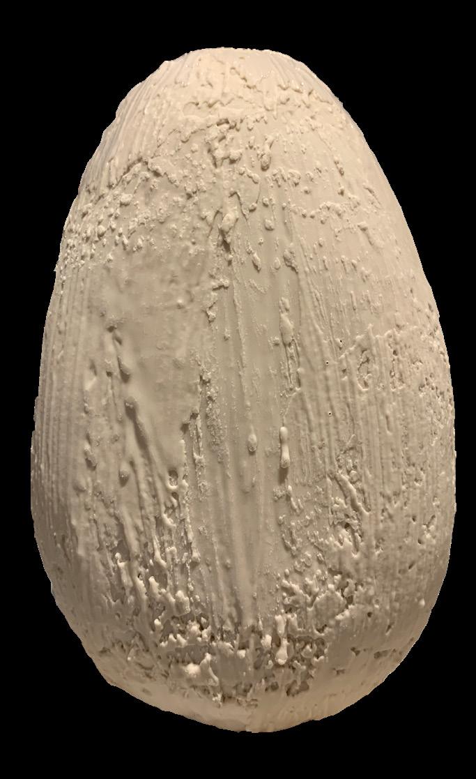
Ice as formwork
The study of water , its states, behaviours and its fluidity as a suitable core.
Water is abundant, can harden and liquefy naturally and is infinitely reusable.
Structure is less dense, it thus expands by 9% when freezes.
Water is densest at 4° C and becomes less dense if it freezes or if it get hotter.
Beyond 100°C water molecules vibrate so much they no longer bond and turns into gas.
Amount of energy a certain amount of water need to loose in order to freeze
Mass of water
-1 cubic meter of water : 1000Kg
-Initial temperature of water 10 °C
-Final temperature of water -10 °C
-Specific volume of water at 10 °C : 0.001000 m³/Kg (Fig 1)
Density = 1/.oo1ooo = 1000Kg/ m³
Change in Enthalpy required
Saturated water at 10 °C : 42.022 Kj/Kg (Fig 1)
Saturated ice at -10 °C: -354.12 Kj/Kg (Fig 2)
The change in enthalpy required for 1 m³ of water to freeze at -10 °C with an initial temperature of 10 °C :
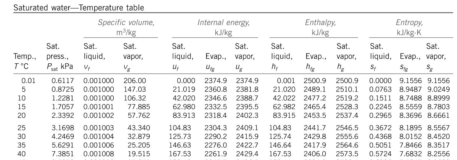
42.022 Kj/Kg - (-354.12 Kj/Kg) = 396.14 Kj/Kg
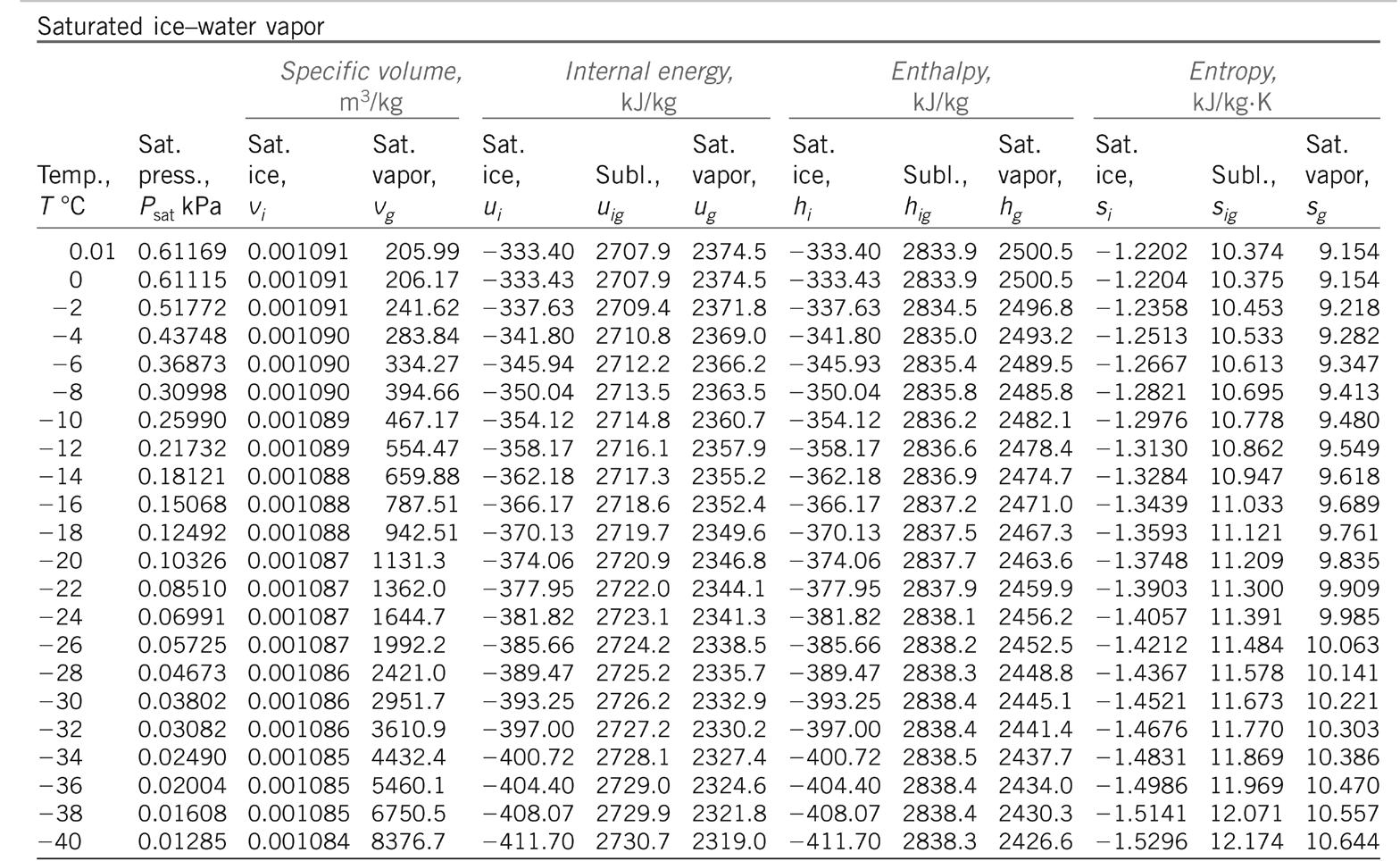
1000 Kg of water need to release 396.140 Kj of energy to freeze.
Favouring ice formation: Ice nucleation-active proteins
The water is sometimes mixed with ina (ice nucleation-active) proteins from the bacterium Pseudonymous syringae. These proteins serve as effective nuclei to initiate the formation of ice crystals at relatively high temperatures, so that the droplets will turn into ice before falling to the ground.
Since the 1970s, P. syringae has been implicated as an atmospheric ‘biological ice nucleator’, with airborne bacteria serving as cloud condensation nuclei. Recent evidence has suggested that the species plays a larger role than previously thought in producing rain and snow. These Ina proteins are also used in making artificial snow
Accelerating Ice melting: Sodium chloride (Salt)
The addition of salt onto an ice surface immediately causes melting as soon as it is dissolved by lowering the freezing point of water via a process called freezing point depression. A 10-percent salt solution freezes at 20 degrees Fahrenheit (-6 Celsius), and a 20-percent solution freezes at 2 degrees Fahrenheit (-16 Celsius).

Moldavia 1050M
Mongolia 3500M
Mexico 2722M
Poland 1025M
Portugal 1967M
Peru 5000M
Pakistan 1600M
Republic of Macedonia 2525M
Romania 1084M
Russia 4500M
Coldest Regions World Wide
Location:East Antarctic Plateau
Average Temp:-10°C to -60°C
Altitude: 3888M
Location:Khazakhstan
Average Temp:-20°C
Altitude: 3163M
Location: Oymyakon, Russia
Average Temp:-14°C
Altitude: 3163M
Location: Greenland
Average Temp:-21°C
Altitude: 3290M
Location: Canada
Average Temp:-8°C
Altitude: 1713M
Location: Alaska
Average Temp:-11°C
Altitude: 3000M
Location: Finland
Average Temp:-19°C
Altitude: 1742M
Location: Estonia
Average Temp:-9°C
Altitude: 2600M
Location: Mongolia
Average Temp:-34°C
Altitude: 3500M
Location:Denmark
Average Temp:0°C
Altitude: 2300M
Location:Latvia
Average Temp:-3°C
Altitude: 1020M
Location:Austria
Average Temp:-2°C
Altitude: 2150M
Location:Switzerland
Average Temp:-4°C Altitude: 1400M
Location:Ukraine
Average Temp:0°C
Altitude: 1372M
Location:Lithuania
Average Temp:-28°C
Altitude: 1600M
Location:Nepal
Average Temp:7°C
Altitude: 2627M
Location:Belarus
Average Temp:-6°C
Altitude: 2047M
Location: Norway
Average Temp:2°C
Altitude: 1520M
Serbia and Montenegro 2196M
San Marino 2500M
Slovakia 1061M
Slovenia 1327M
Spain 1500M
Sweden 1274M
Switzerland 1400M
South Korea 1614M
Ukraine 1372M
United Kingdom 1460M USA 3330M
Uzbekistan 3309M
Tajikistan 3600M
Turkey 2000M
Taiwan 3000M
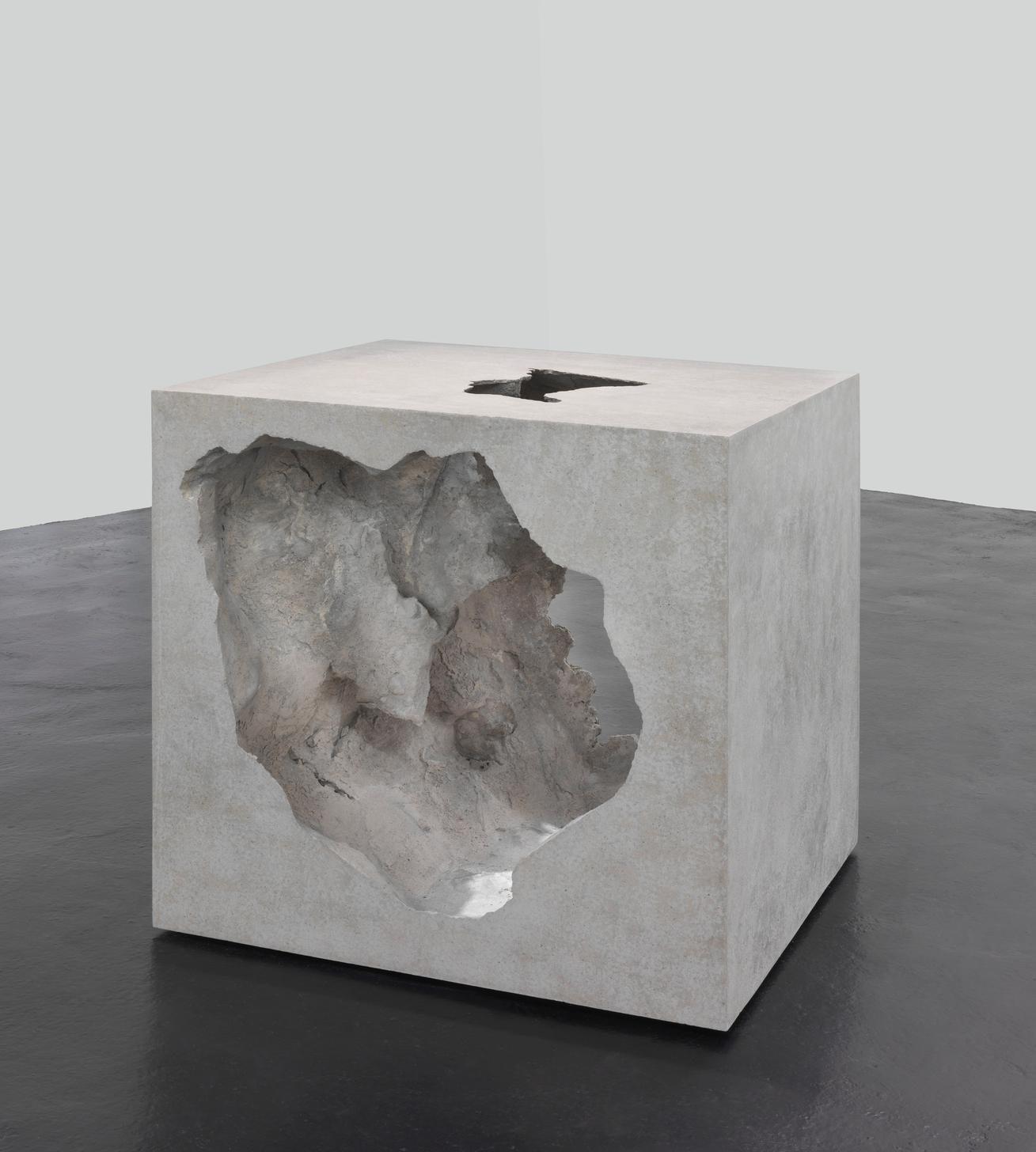
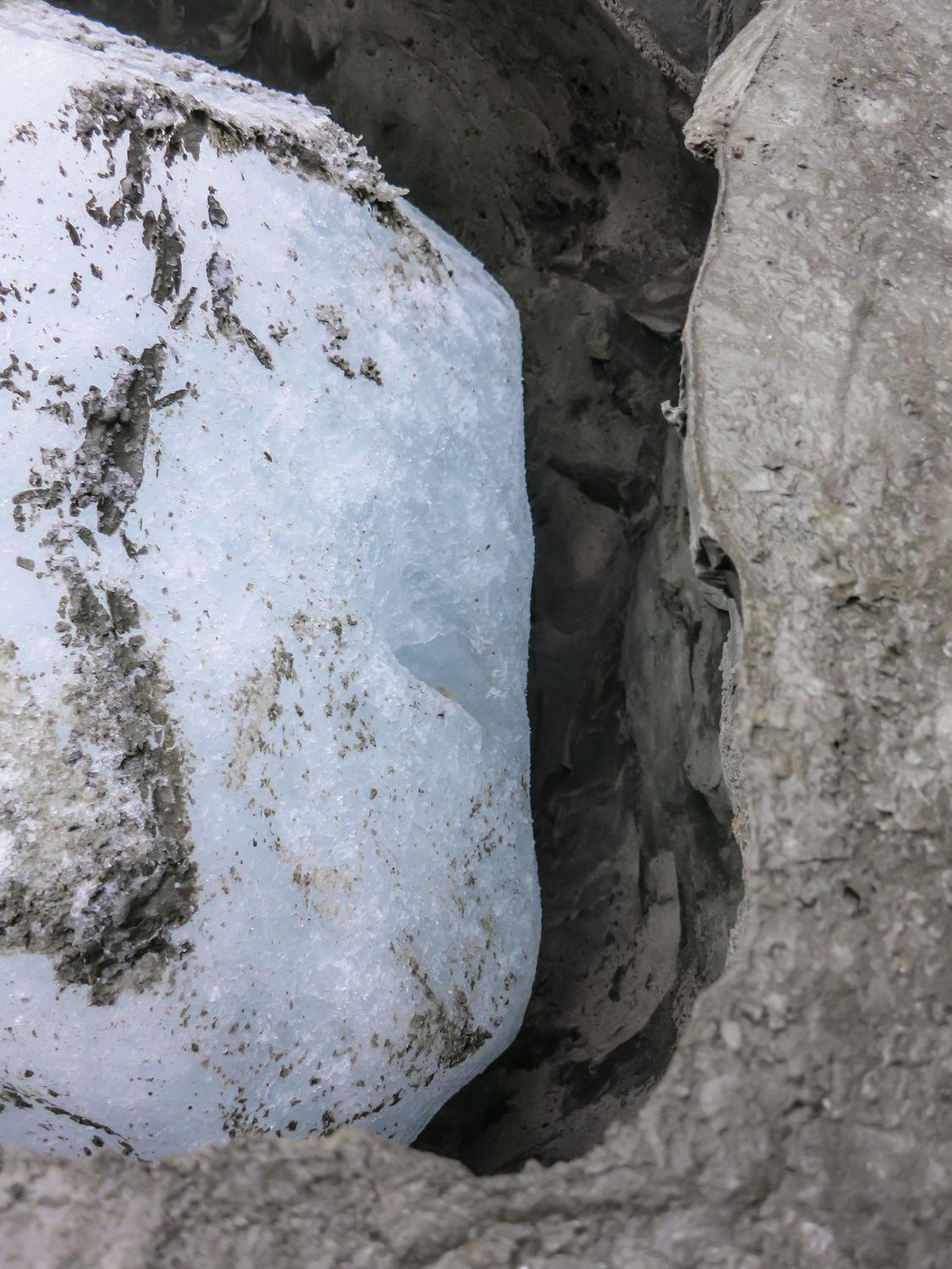
2Self demoulding core
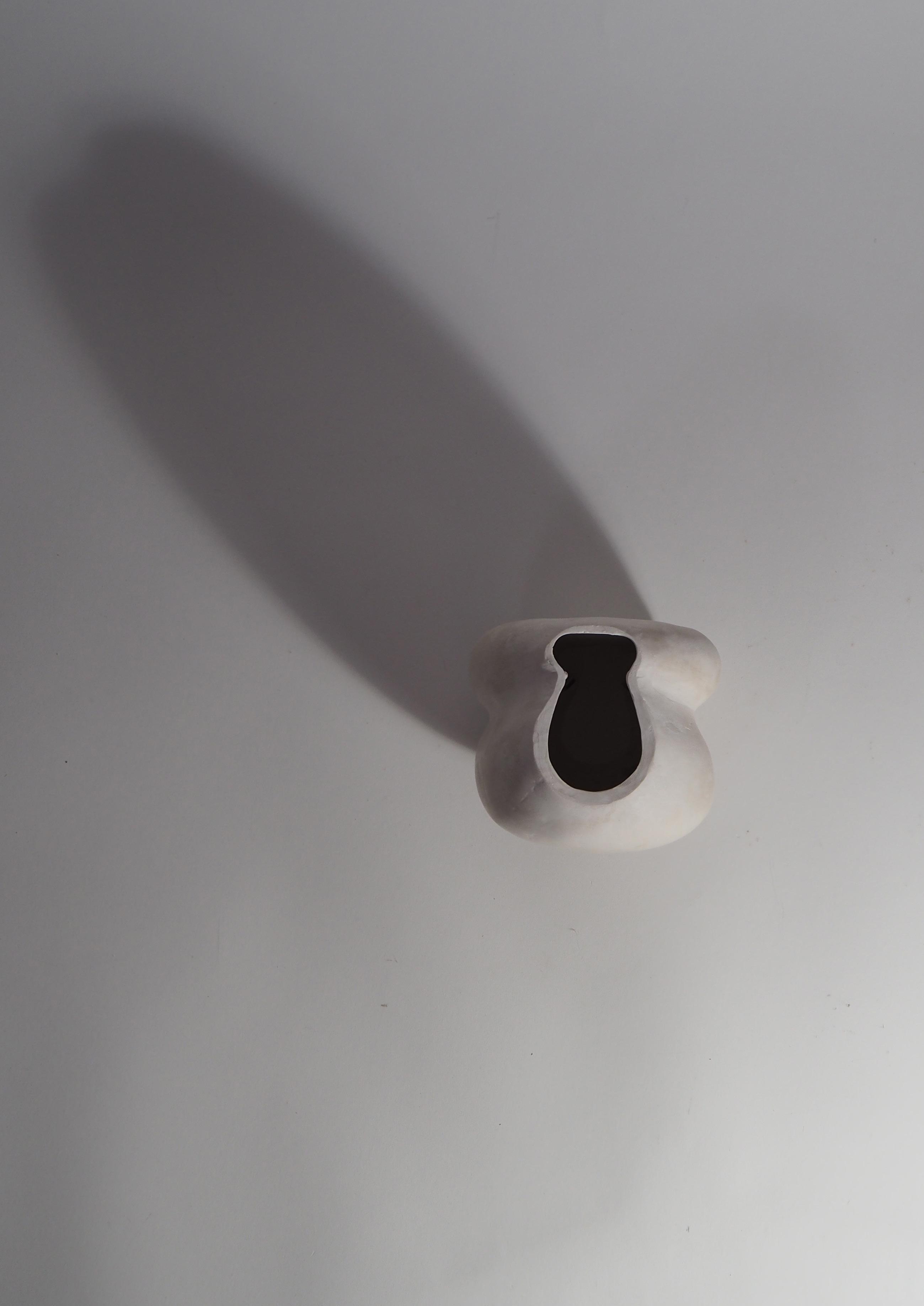
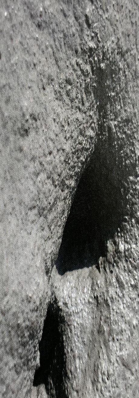
Ice as a demoulding formwork, creating spaces through the void it leaves behind.
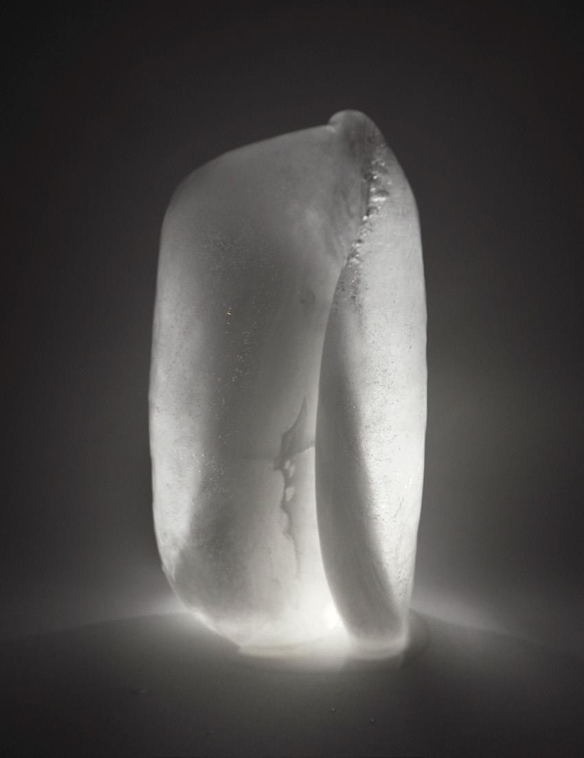

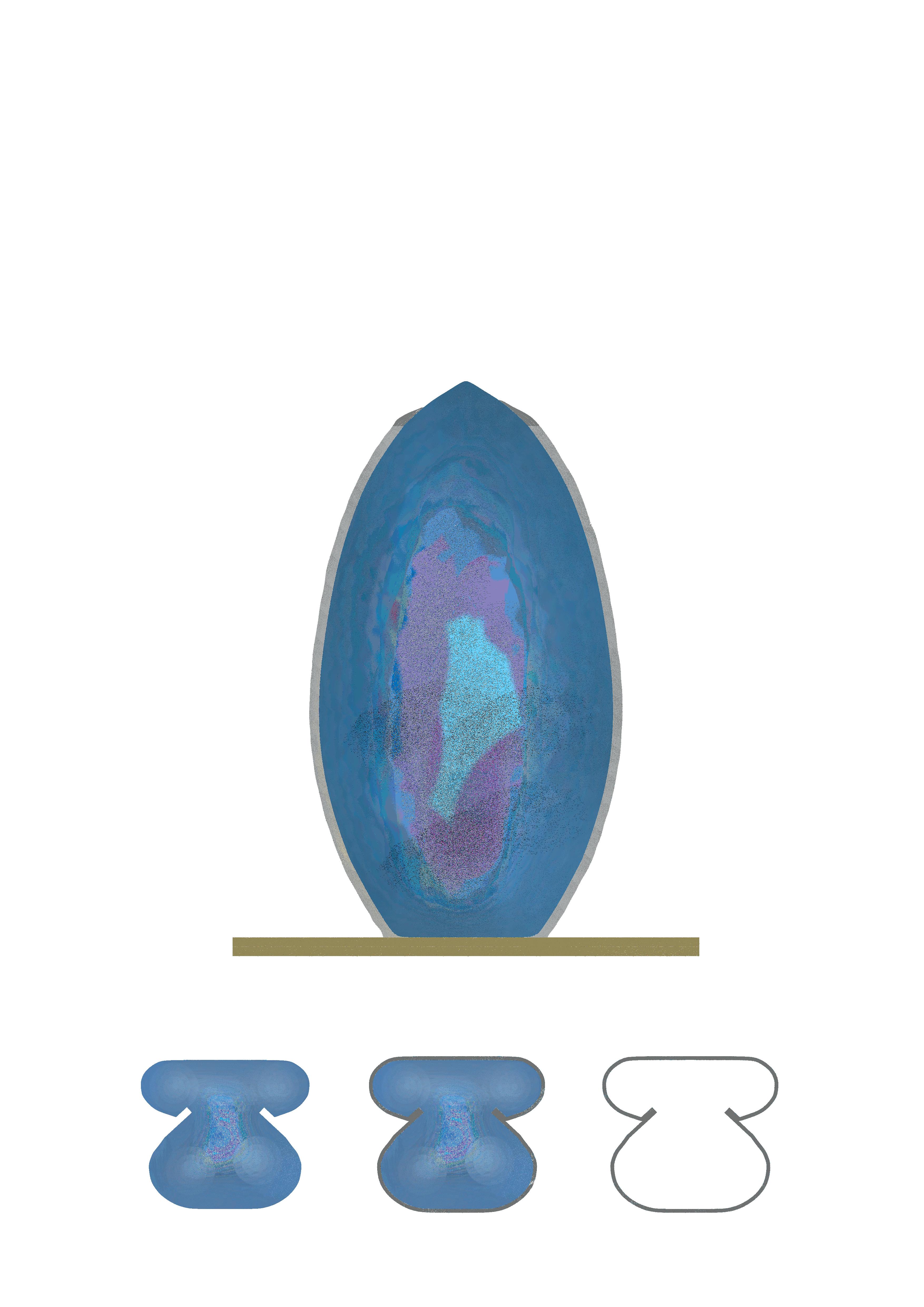

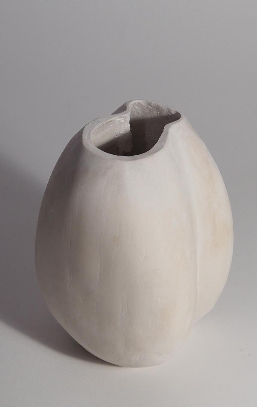

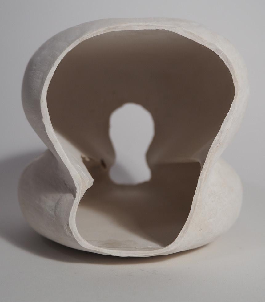


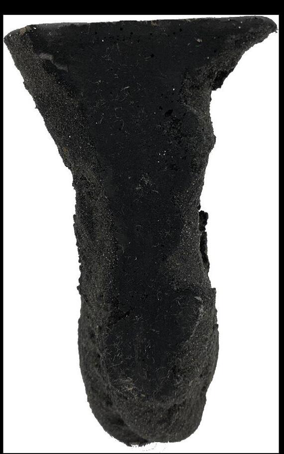
The negative of a staircase used as falsework is captured by the water filled blader and is solidified when the liquid freezes creating a formwork. The staircase is successfully imprinted on to the ice but due to the removal of the falsework, the latex does not remain gripped onto the ice due to the stress removal.
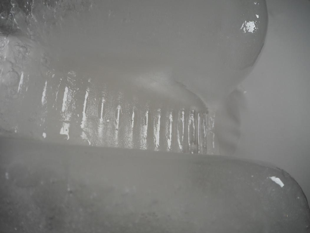
Thus the inside of the membrane would need to be textured to provide anchoring points

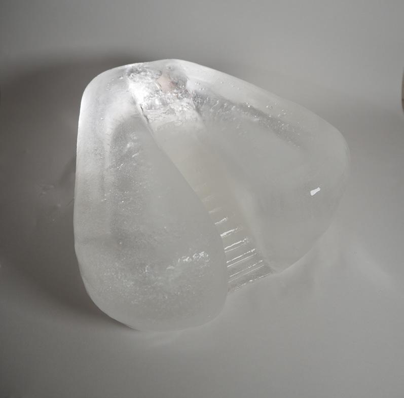
Due to scale and nature of uneven application using a brush instead of spray, the external form of the staircase is lost resulting in a slope.
(see page ...)
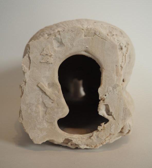
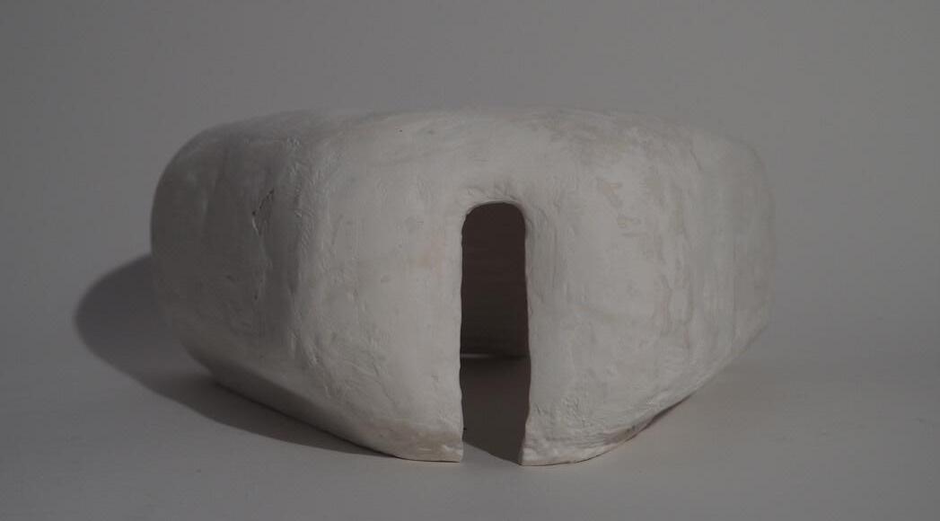
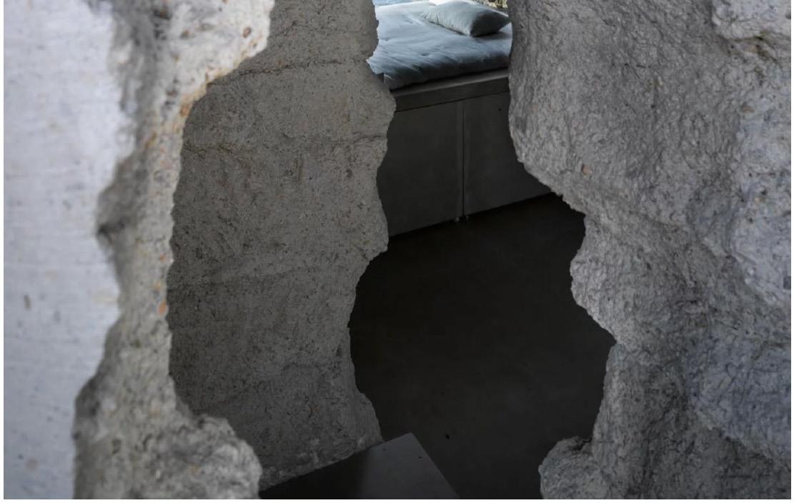
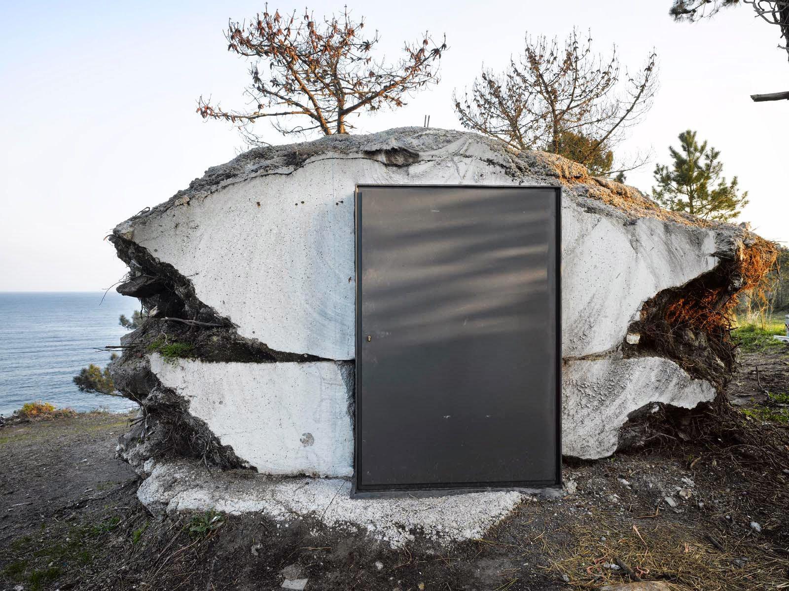
The negative of a door is pressed against the water filled bladder and left in during the casting and is then puled out leaving the void of the door opening.
(see page...)
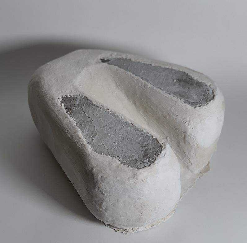
The positive of two benches is pushed on either side of the water blader creating symmetry for the budge to go in the direction of falsework imprints that require more water pressure ( stairs ), and creating the positive of a bench on the inside of the shell embedded with the wall.
(see page...)

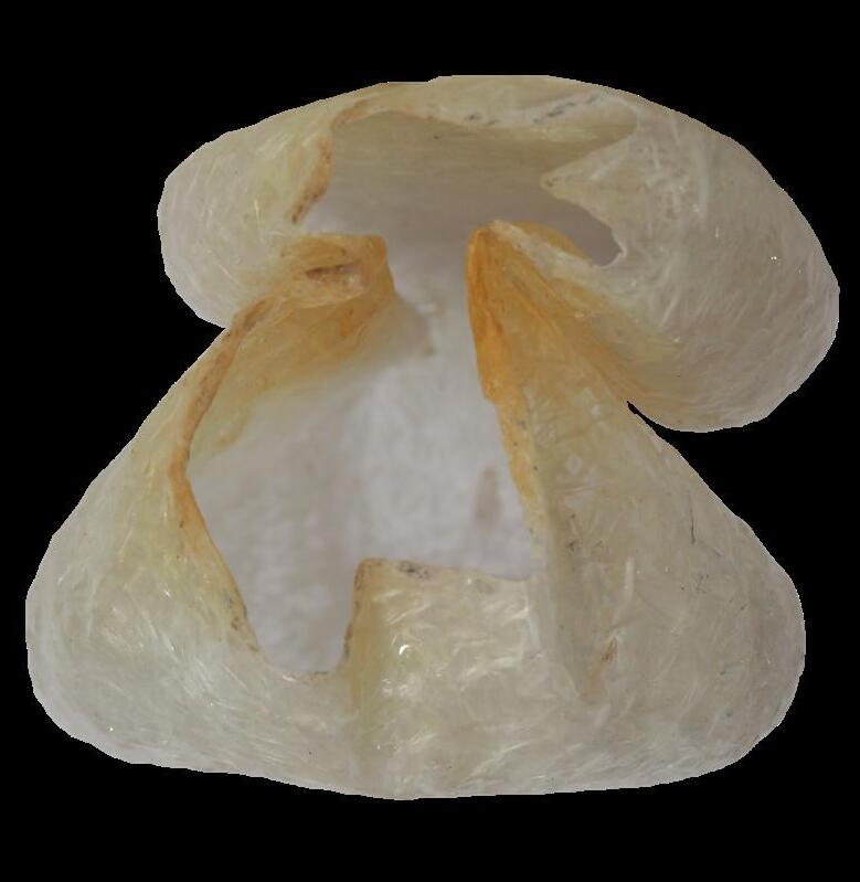
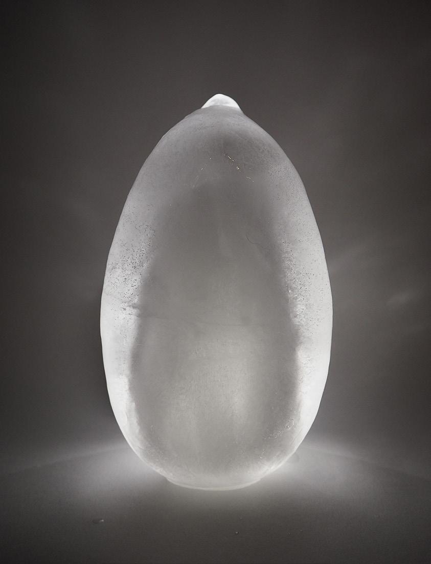
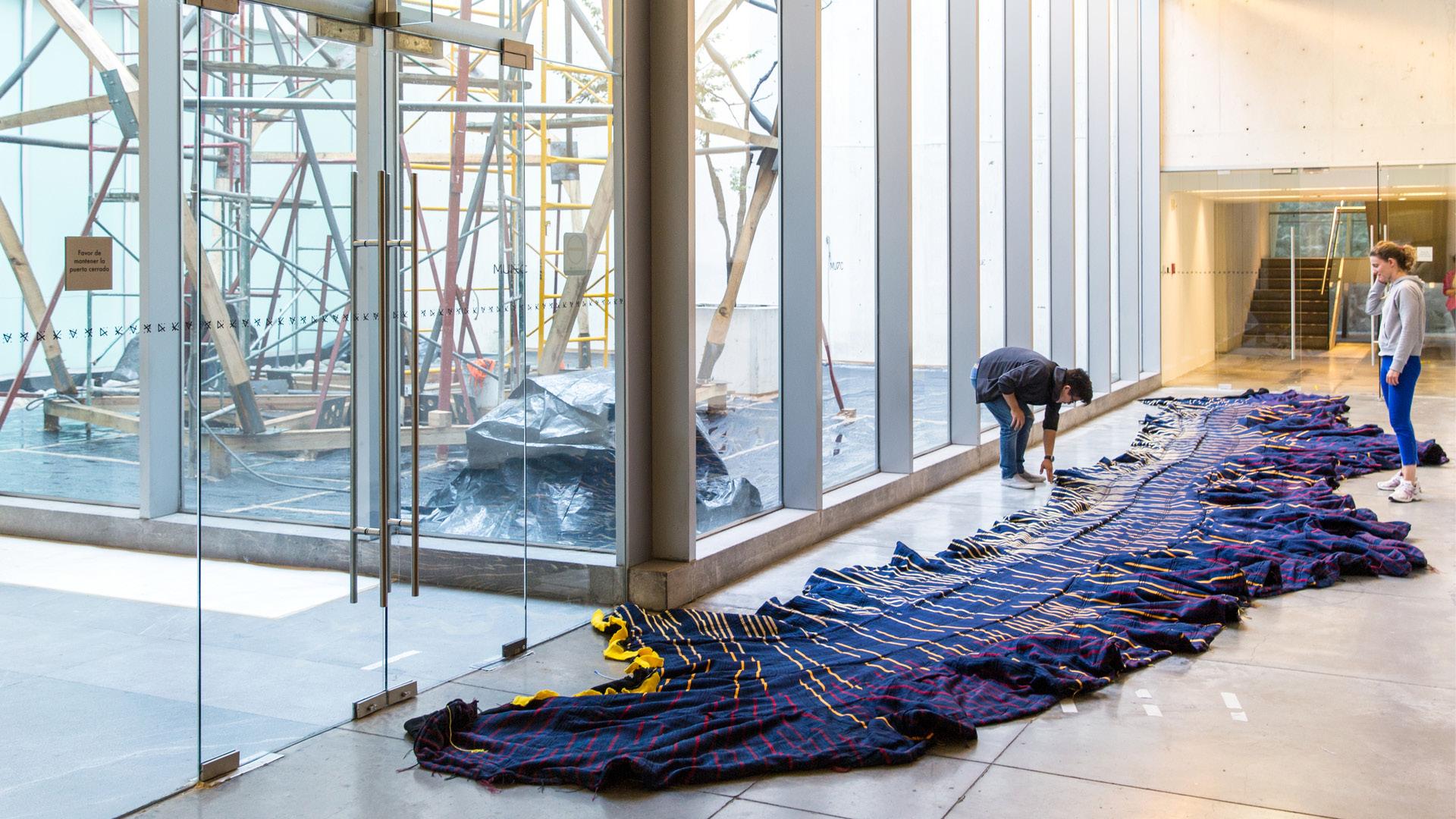
The Vessel. 3
Study of membranes to house the water core. First the stitch, then the flexibility and form control
Ripstop
Non-flexible material

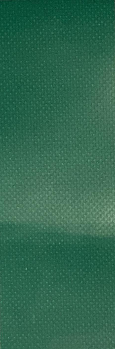

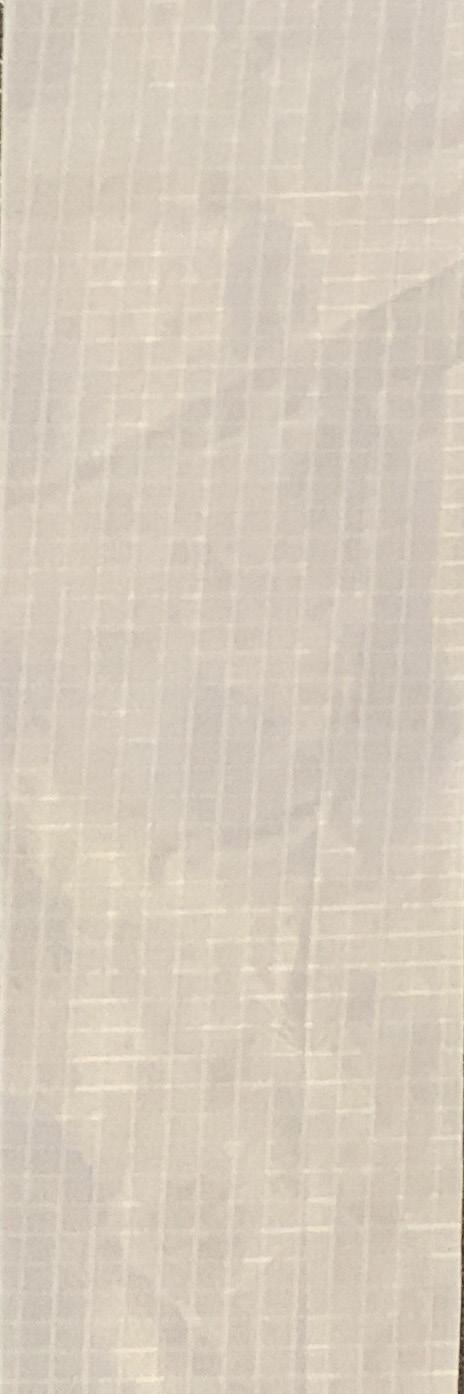
Water resistant
Small scale
Spandex
Very flexible material
Not waterproof Small scale
Natural layered latex


Highly flexible material
Waterproof
Riflex


Stretches easily under pressure
Waterproof Non reinforced
Stretches under high pressure
Waterproof
Reinforced 1
Weakest - stretches more easily
Stretches under higher pressure
Waterproof Reinforced 2
Stretches under higher pressure
Waterproof Reinforced 3
Stretches under high pressure
Waterproof Reinforced 4
Strongest - requires more pressure to stretch

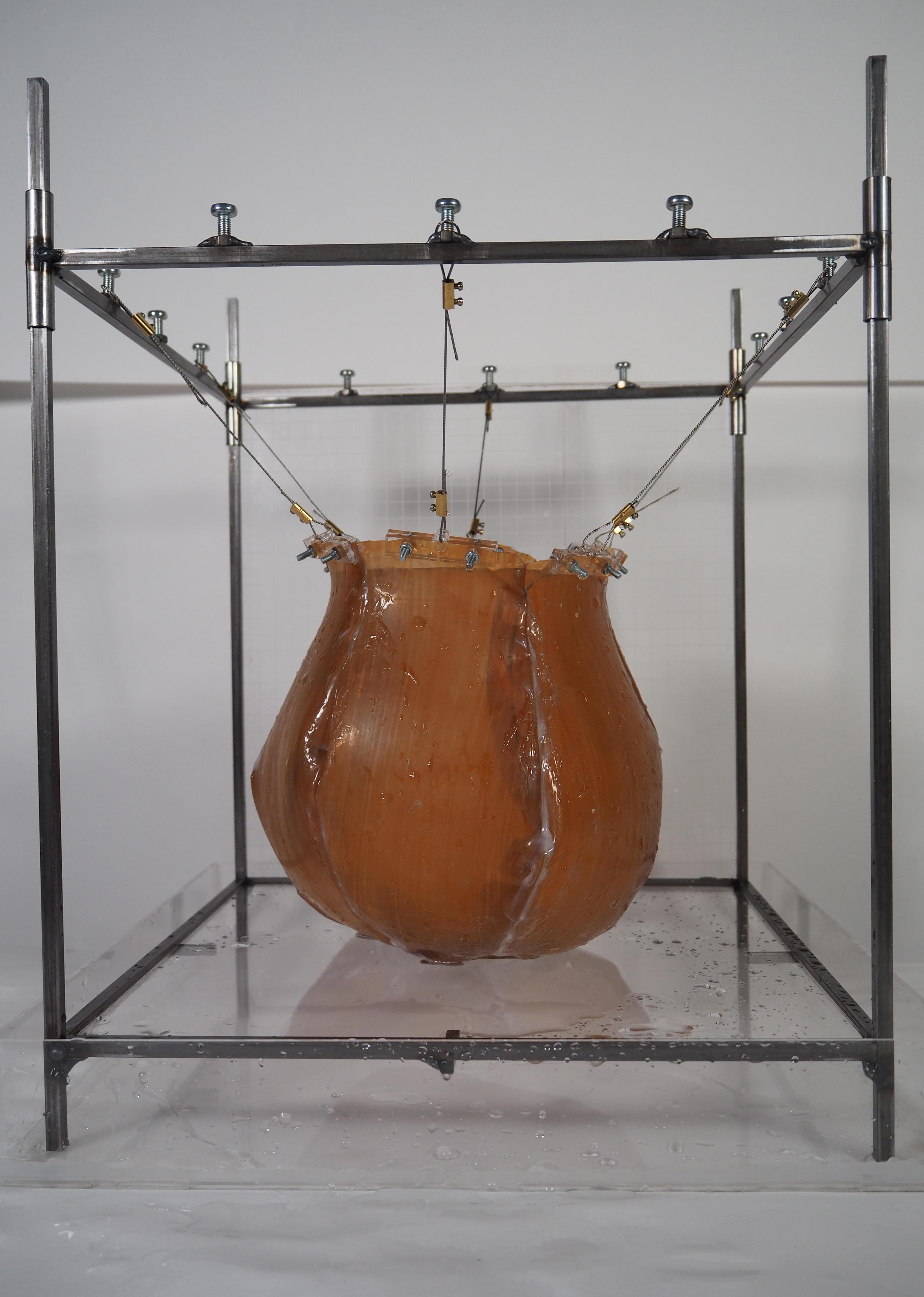
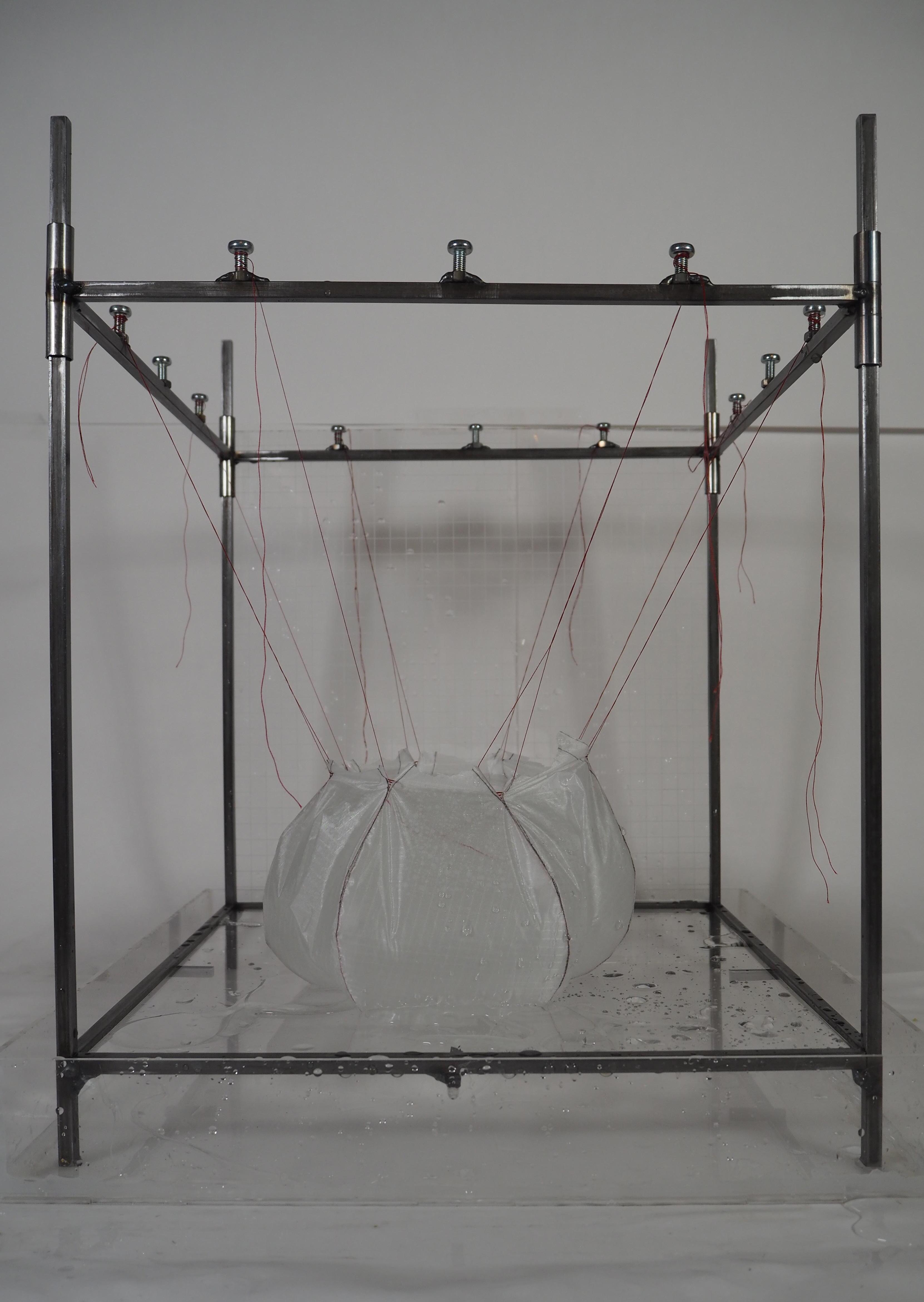
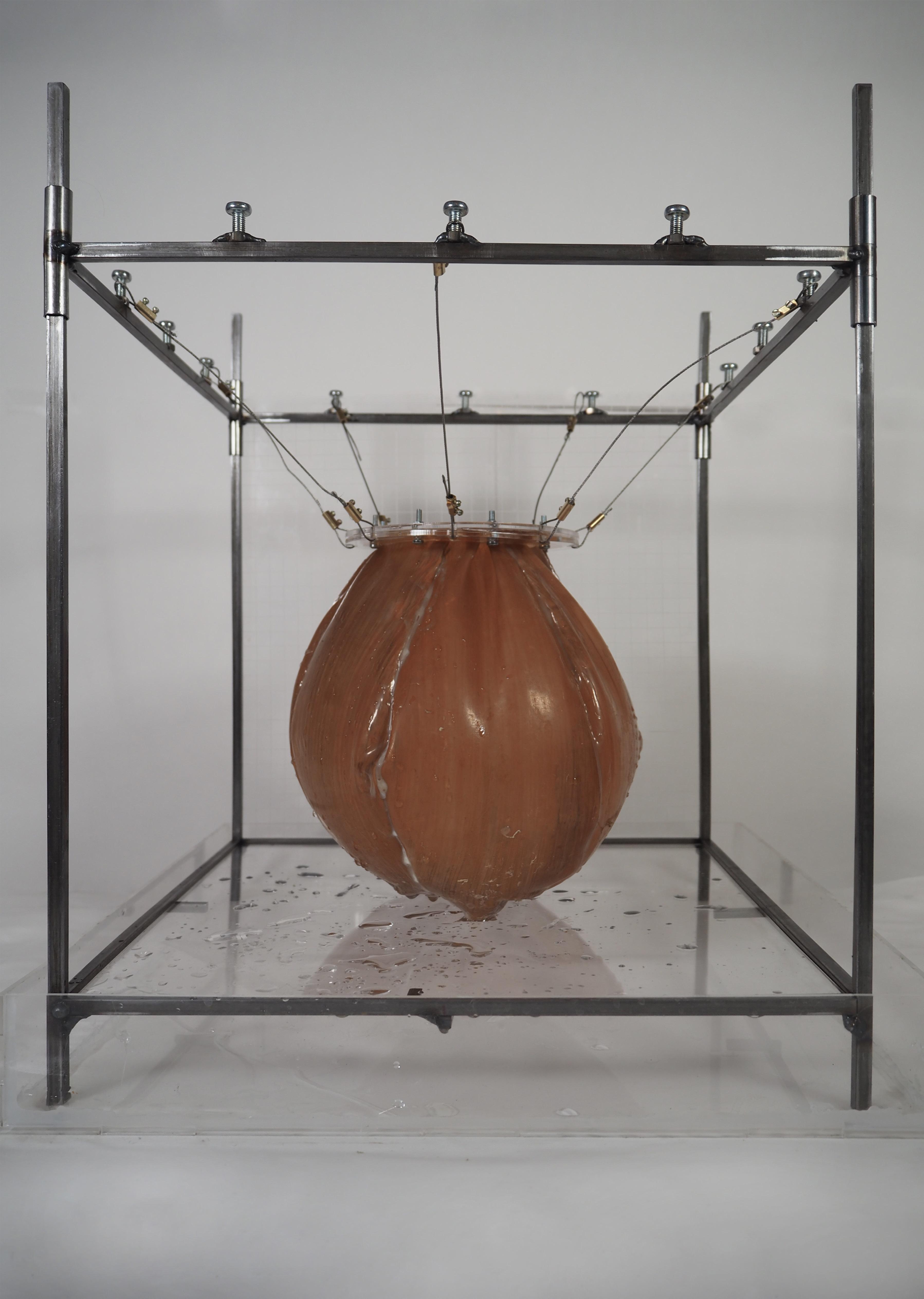
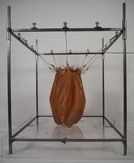
Ajustable steel frame for membrane testing
1:4 Axonometric
Hooks to attach strings
Tightening screw for height ajustments
upper movable frame
Perspex grid for measurment and observation
Perspex tray for water retrieval.
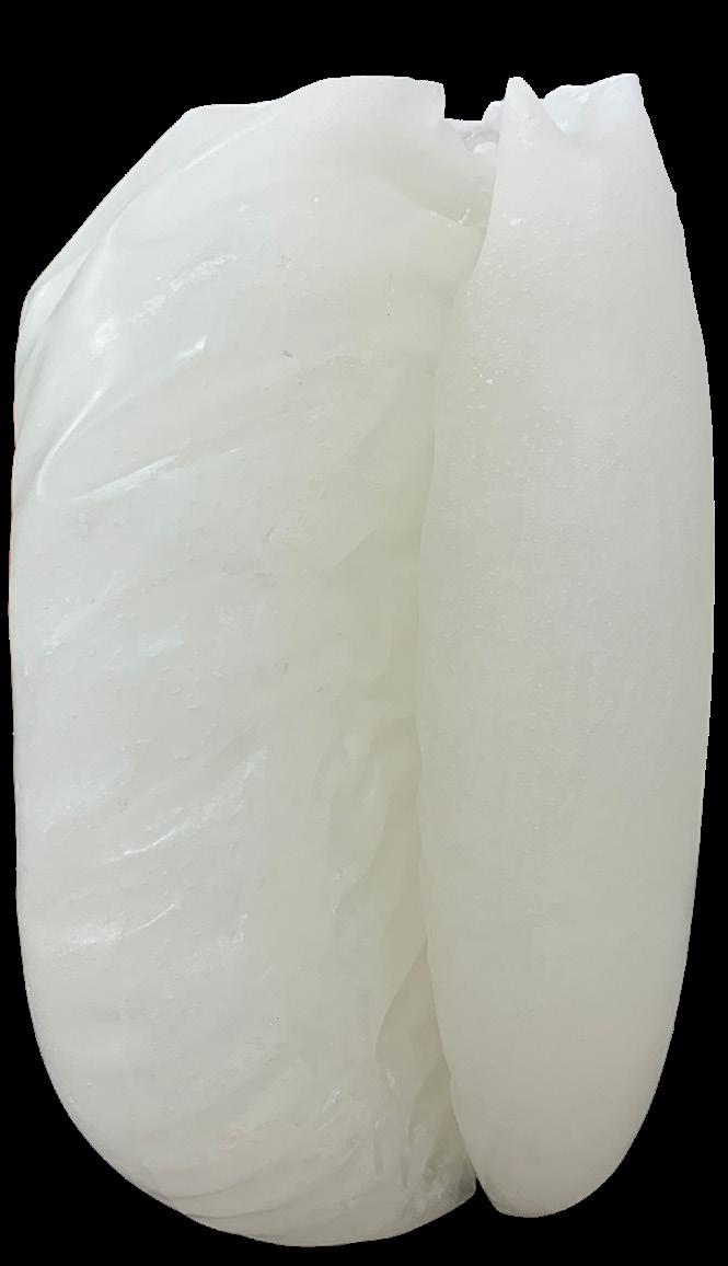
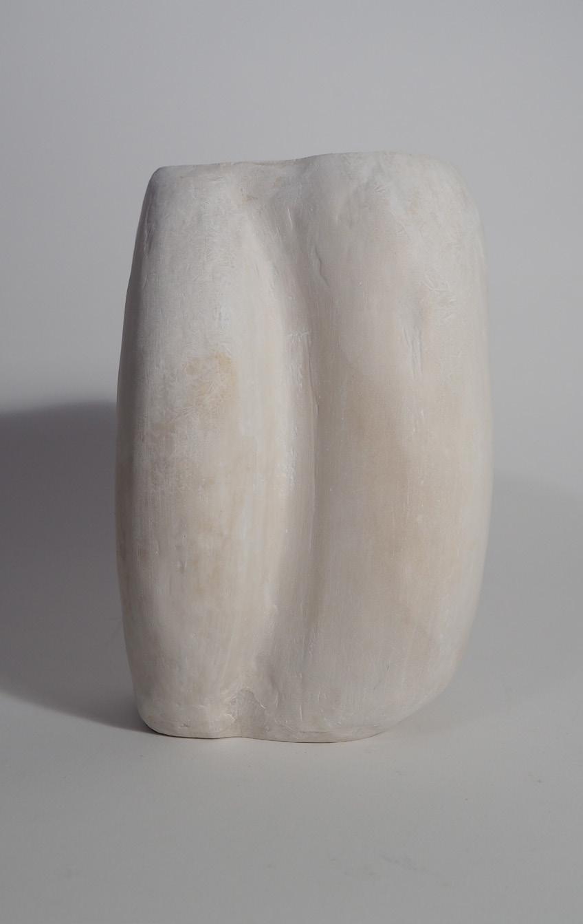
Use of ripstop, non flexible hydrophobic material to develop the stitch patterns. Use of elongated strips wider in the center to control the buldging area.
Conclusion: the strip successfully controls the buldging area however the use of 4 strips does nor result in a continuous round bladder.
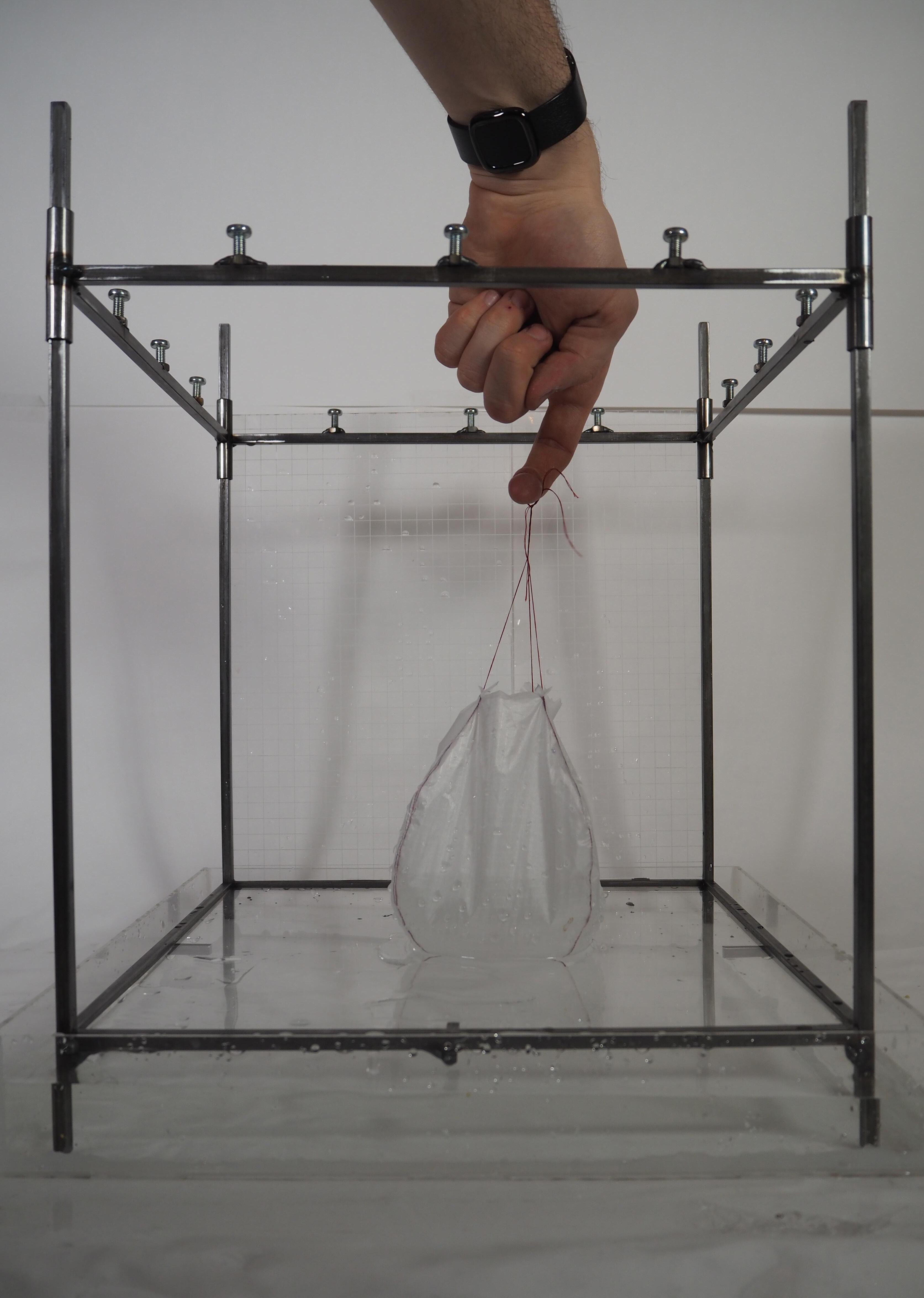
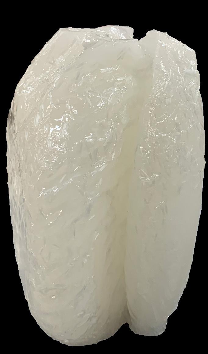
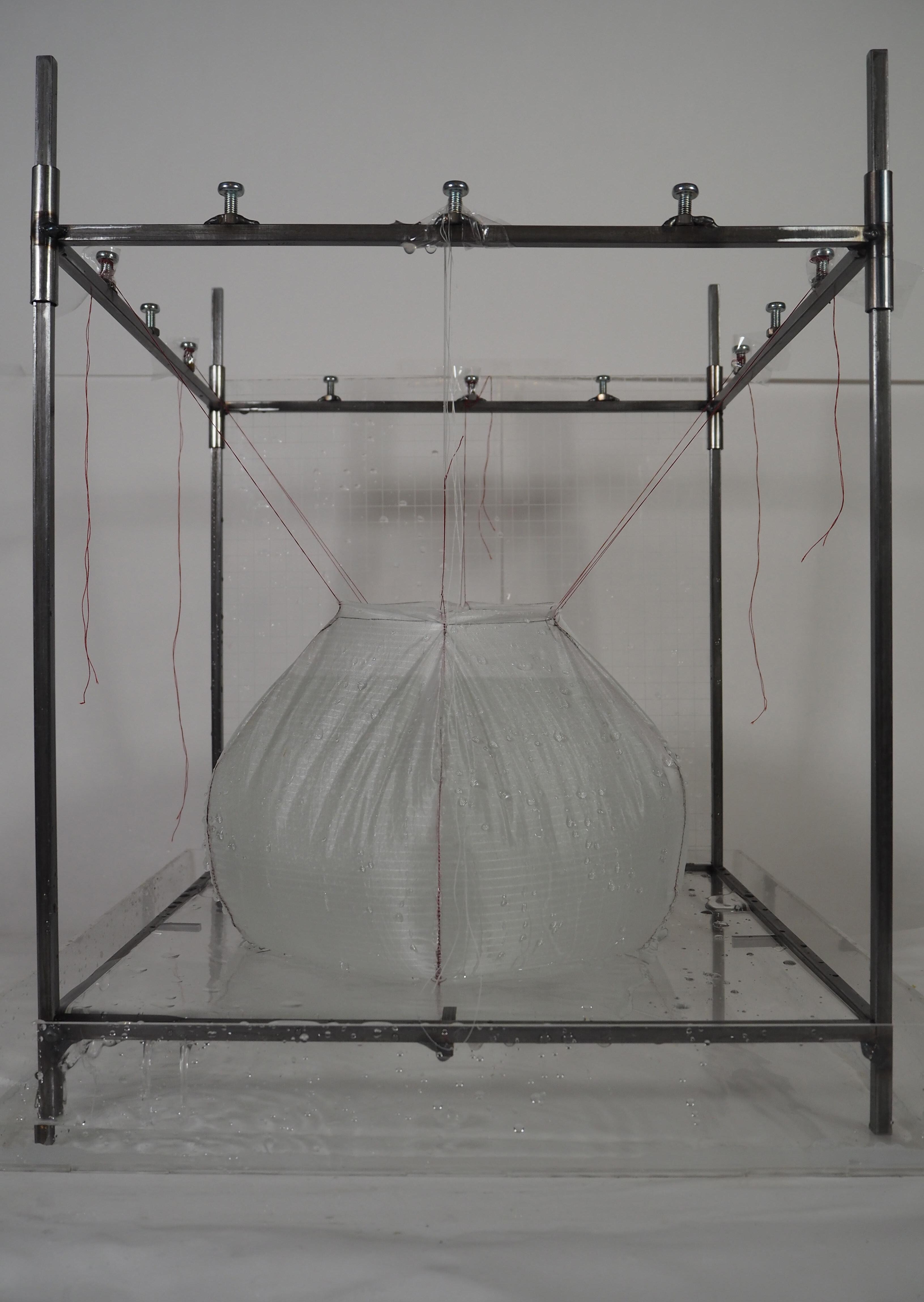
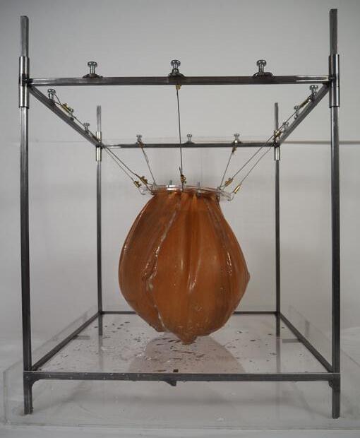
In an attempt to increase the width of the vessel, too many patterns were used for this size of membrane and it did not have a continuous form even when completely filled with water. Due to the shape of the strips there is an excess material at the bottom of the membrane.
Conclusion: Increase number of patterns revealed a proportional relation between the length of the stitch (height) and the give in material for budge control (width).
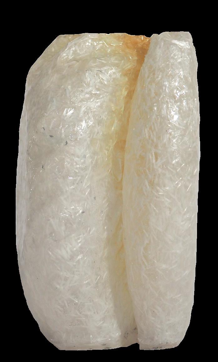
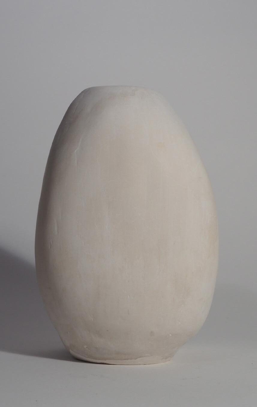
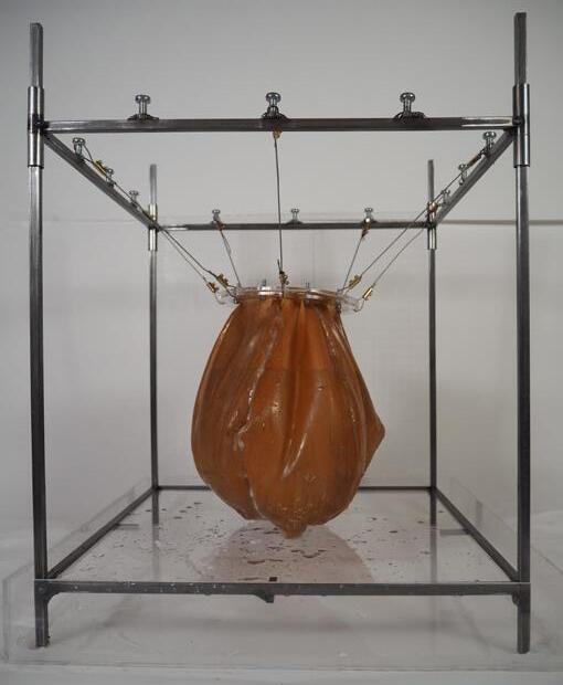
Respecting the rules of proportionality 6 strips were used and a flat base was introduced to avoid material excess.
The resulting form is more continuous but remains hexagonal at the top due to the supporting string attached at one precise point.
Conclusion: A more flexible material and joinery would have to be used in order to keep the tailoring simple and obtain a continuous surface. However due to the combination of the rigidity of the stitch + material and the budge control; The vessel is tighter at the top and bottom and the water pressure is strongest in the center so the top and bottom shrink and it remains self standing when full.
Flip Shear joint. Shear joint.
Strongest joint, offers least flexibility at overlap. Strongest , reduced flexibility at seem.
Flip Shear joint.
Weakest joint, offers most flexibility at seem and flush out surface
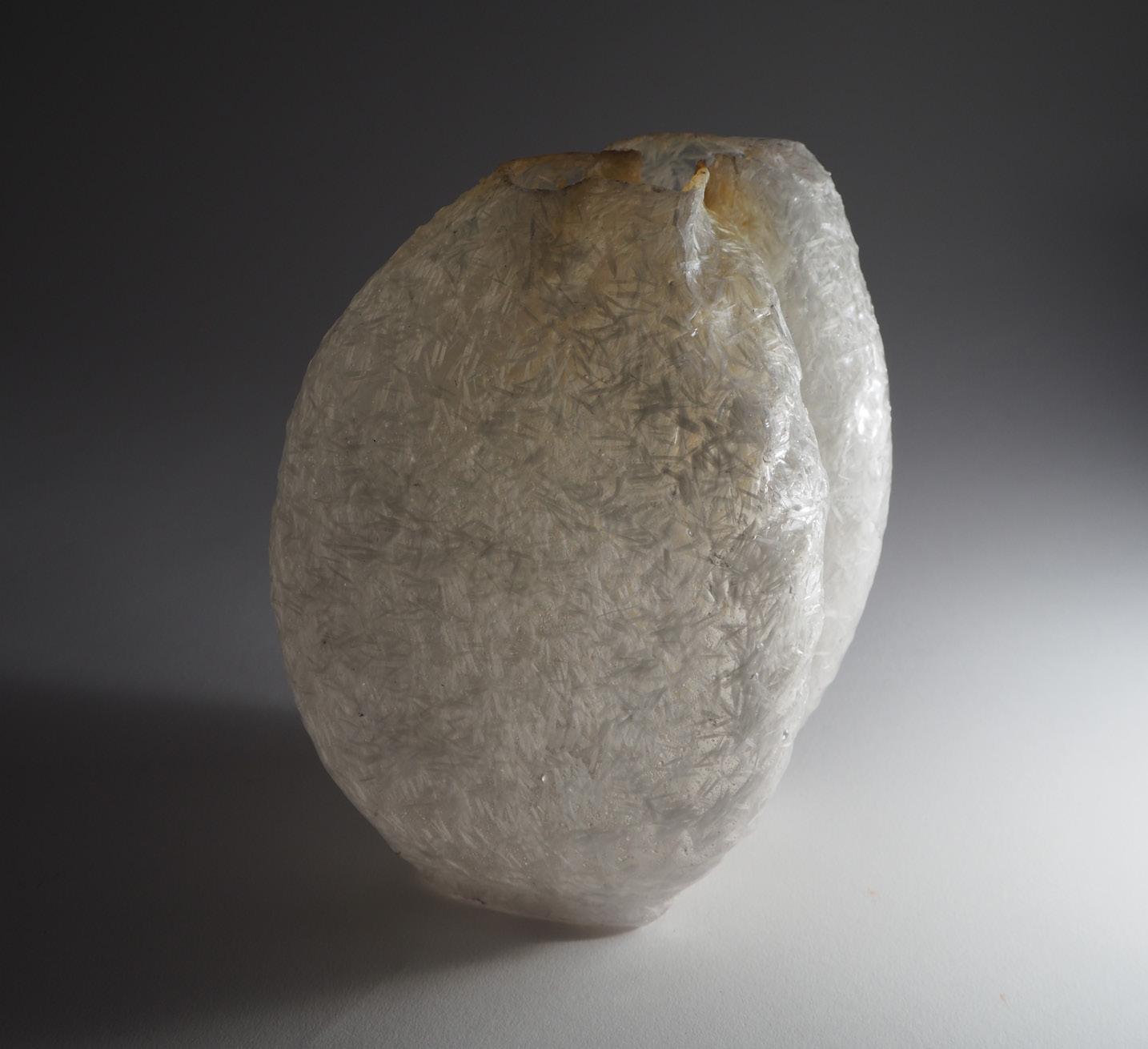
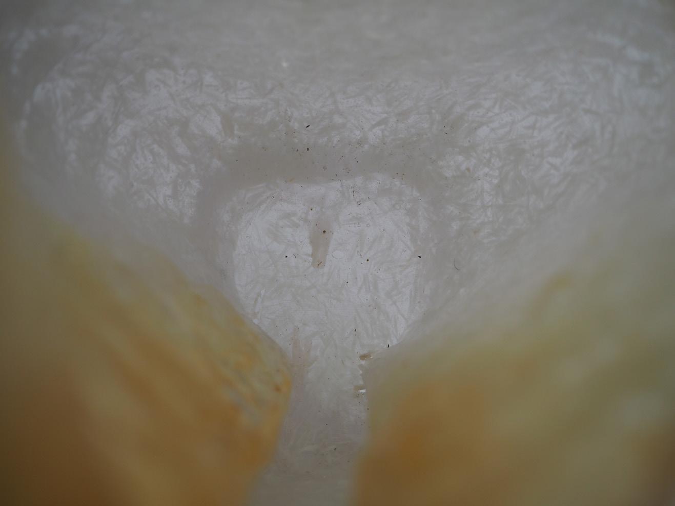
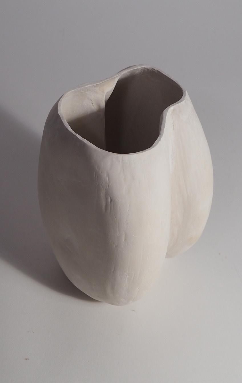
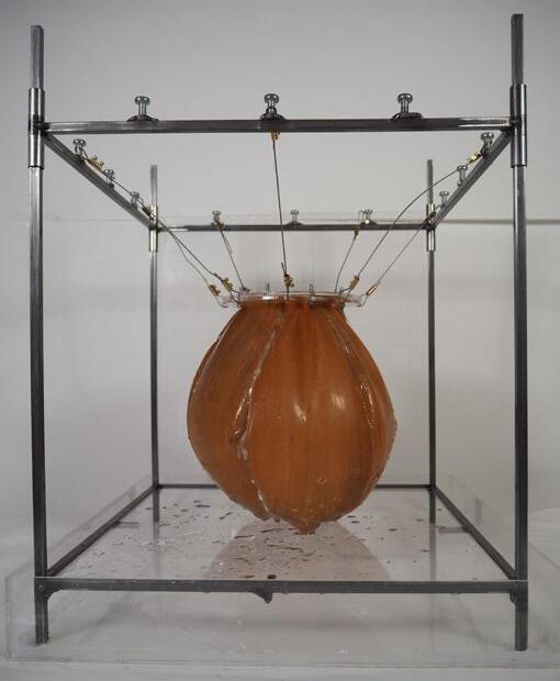
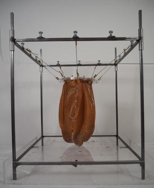
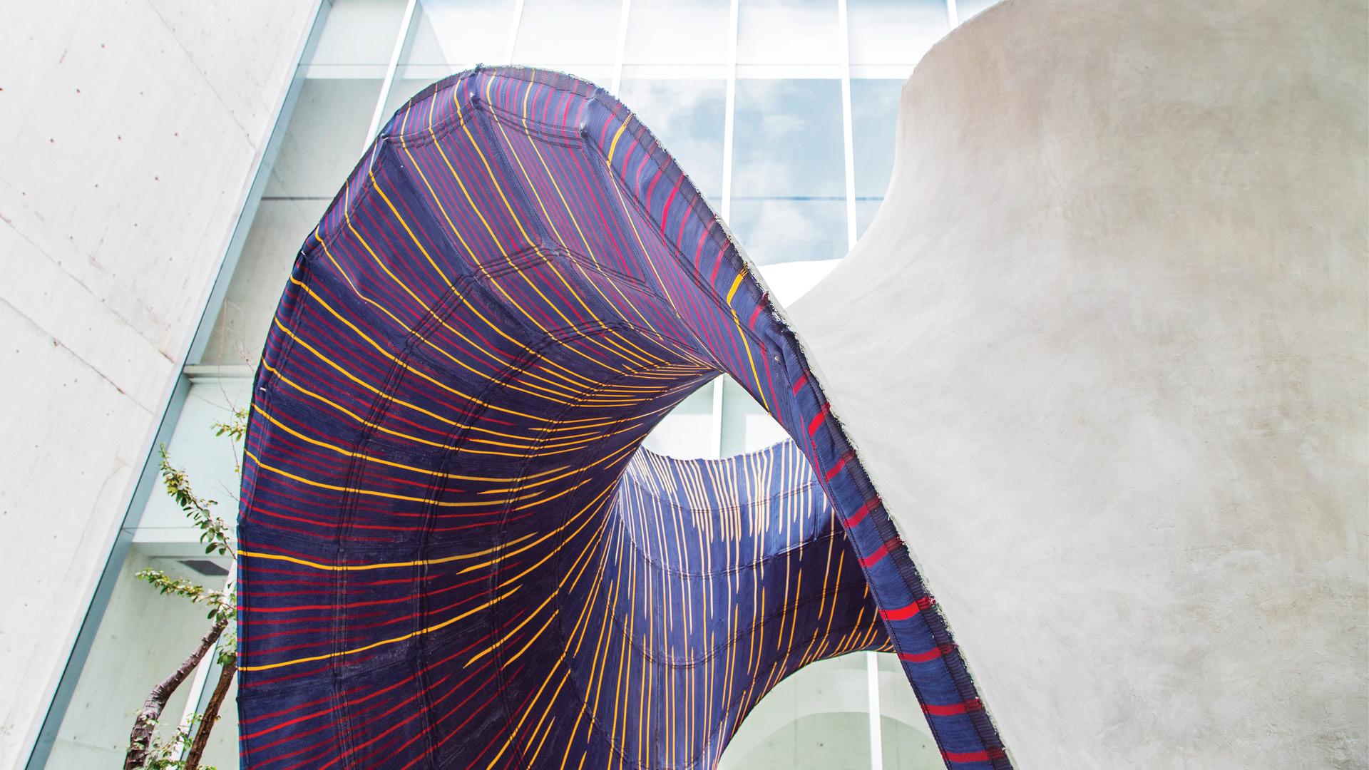
Use of a 7 layered natural latex membrane which highly flexible and can be bonded together while remaining flexible at the joint. Change in material with the same 6 strip pattern using the top to top joint to obtain a smooth outer surface.
A series of clamp joints are introduce to hang the membrane on steel wires with adjustable lengths to manipulate the top edge.
(Scan Qr code for video)
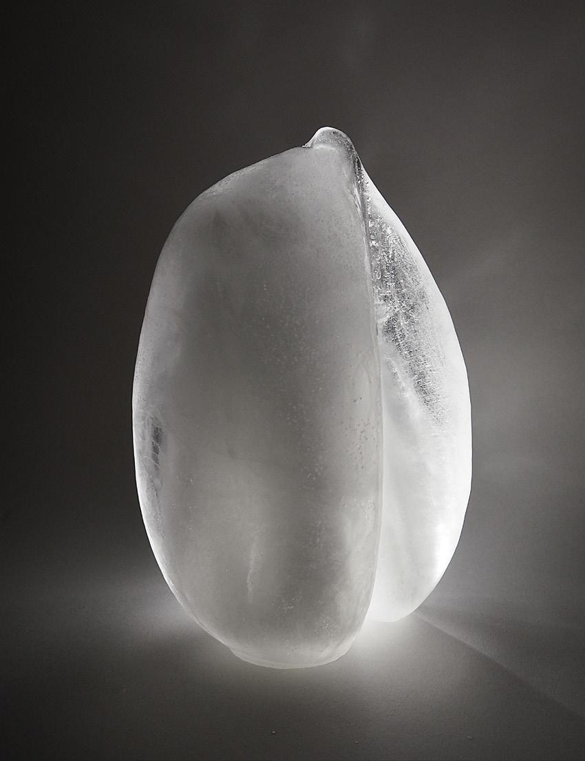
1:1

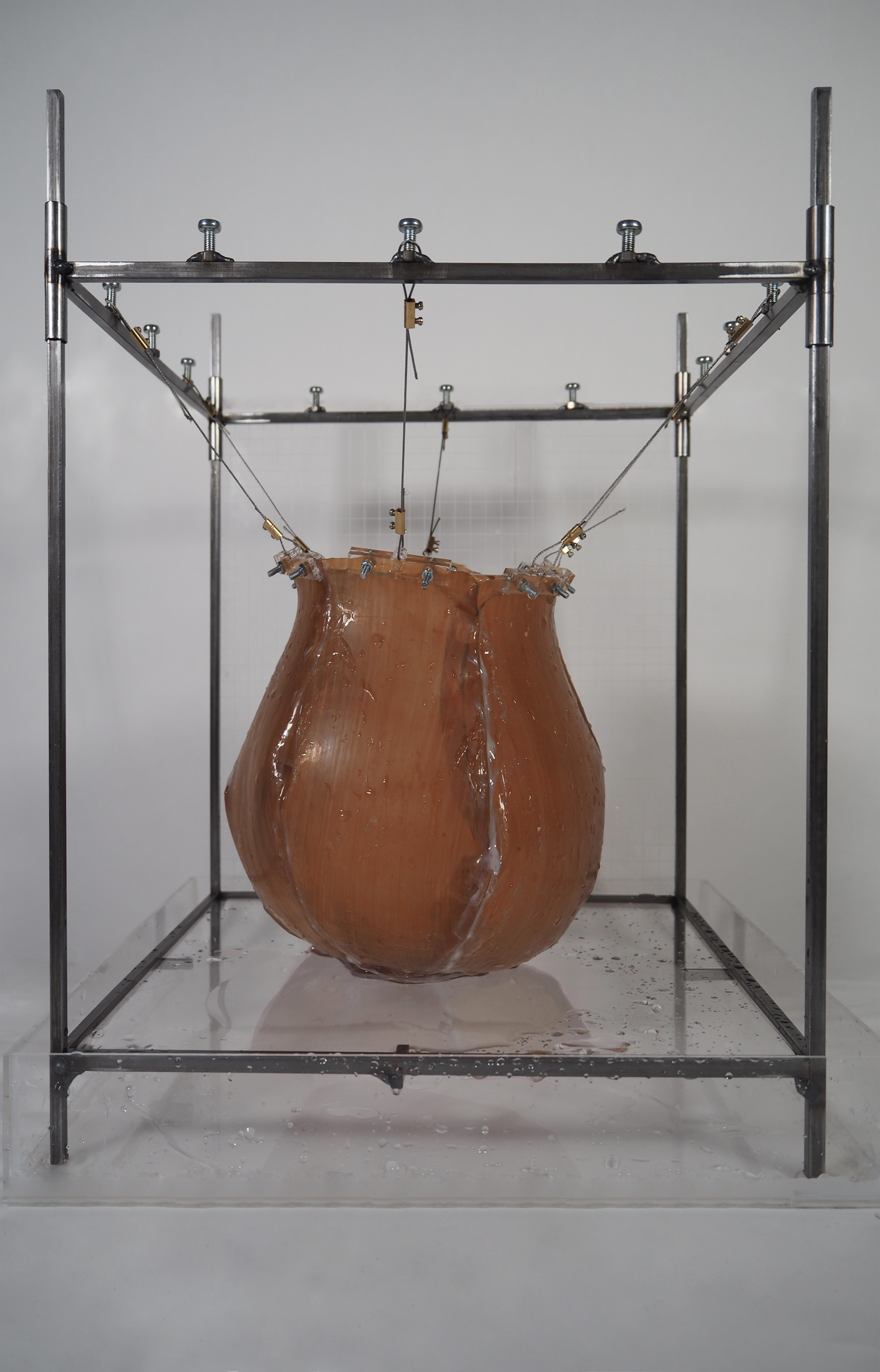
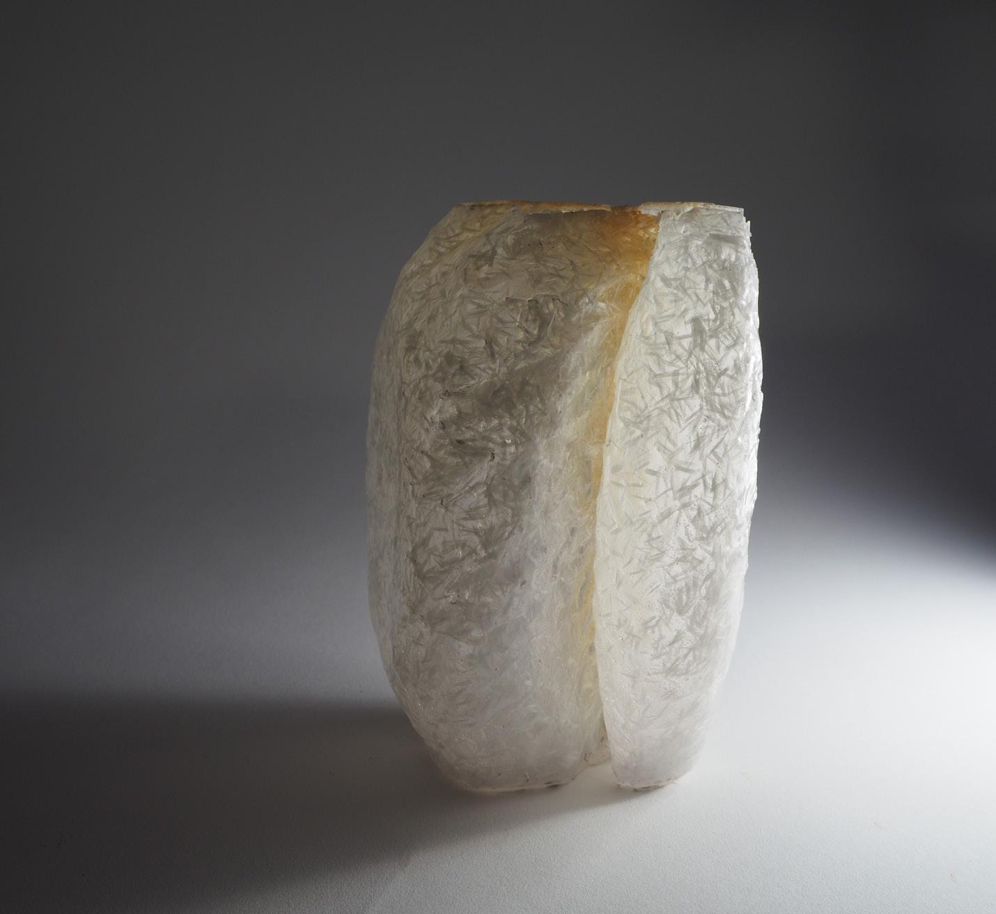
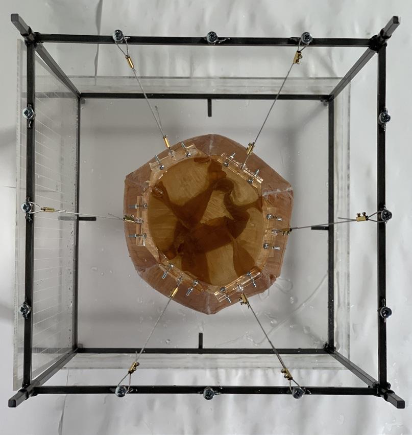
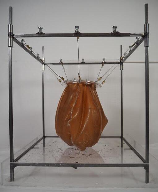
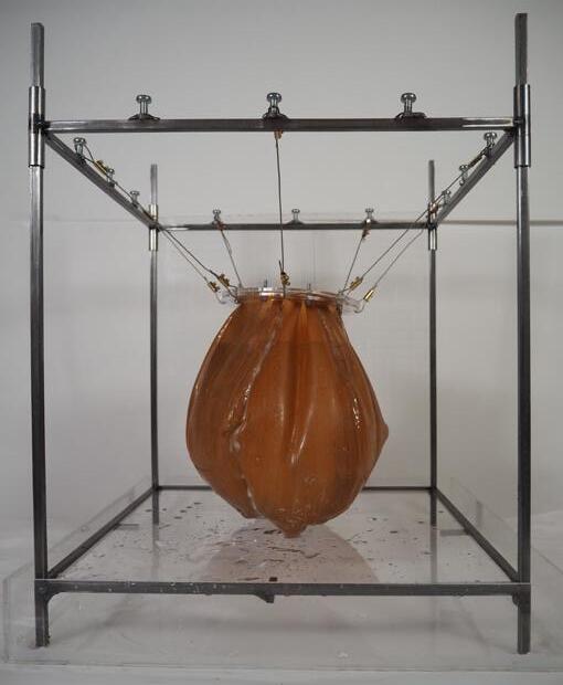
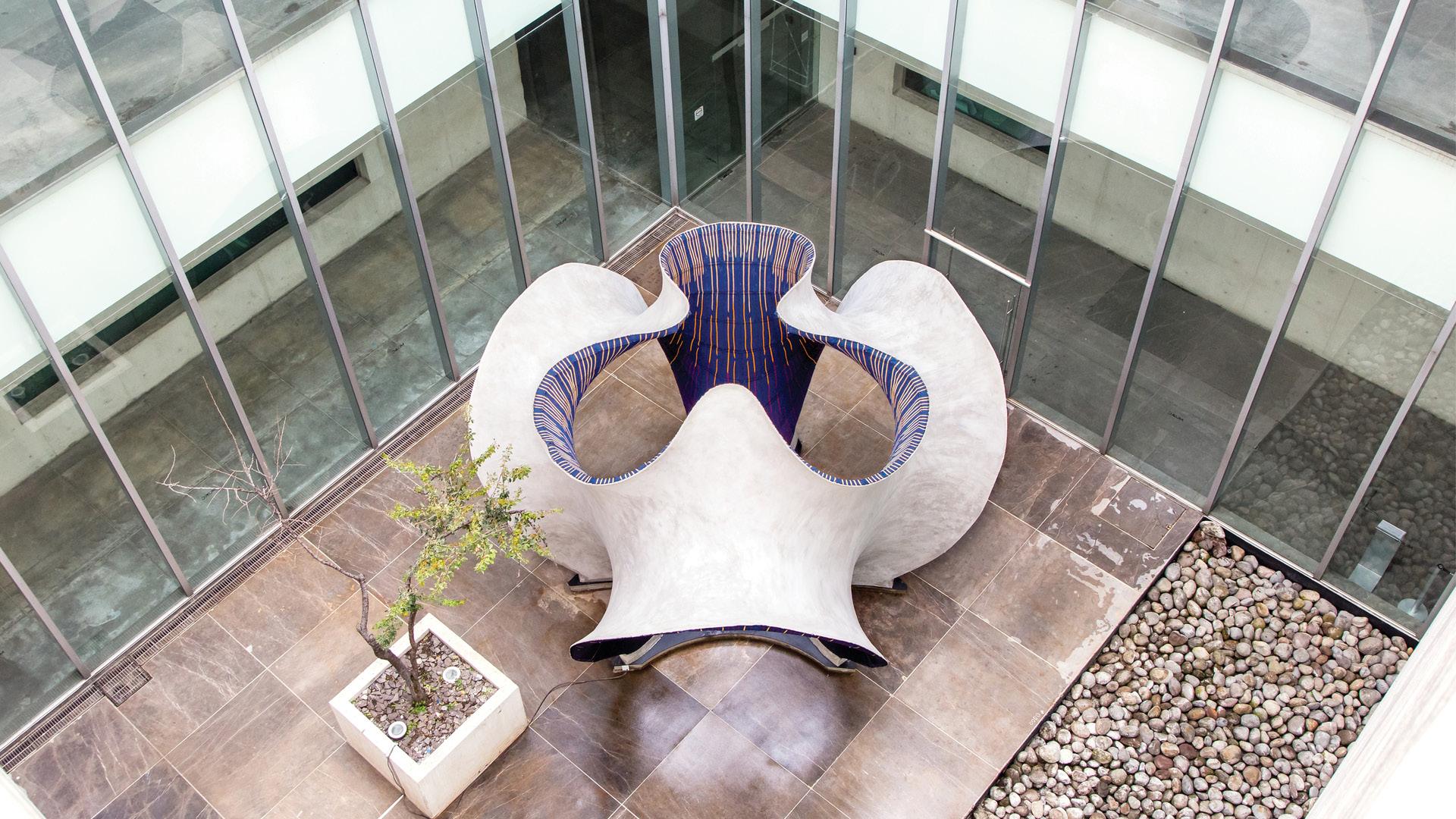
Introduction a 2 piece circular diaphragm that would provide a clear edge at the top of the shell for casting. In addition this use of a flat diaphragm allows for the manipulation of the steel wires to incline the top to a required degree, depending on roof requirements.

(Scan Qr code)
Conclusion: The introduction of a diaphragm adds control to the process and does offer the possibility to receive roofs at different angle however when angled the buldging area moves to the lower side of the diaphragm as material tension increases on the upper side.

Step 1 Place modules
Step 2 Attach vessel
Step 3 Fill with water
Step 4 Freeze
Step 5 Remove modules
Step 6 Apply concrete (Via Tyrolean flicker)
Step 7 Leave to self demould
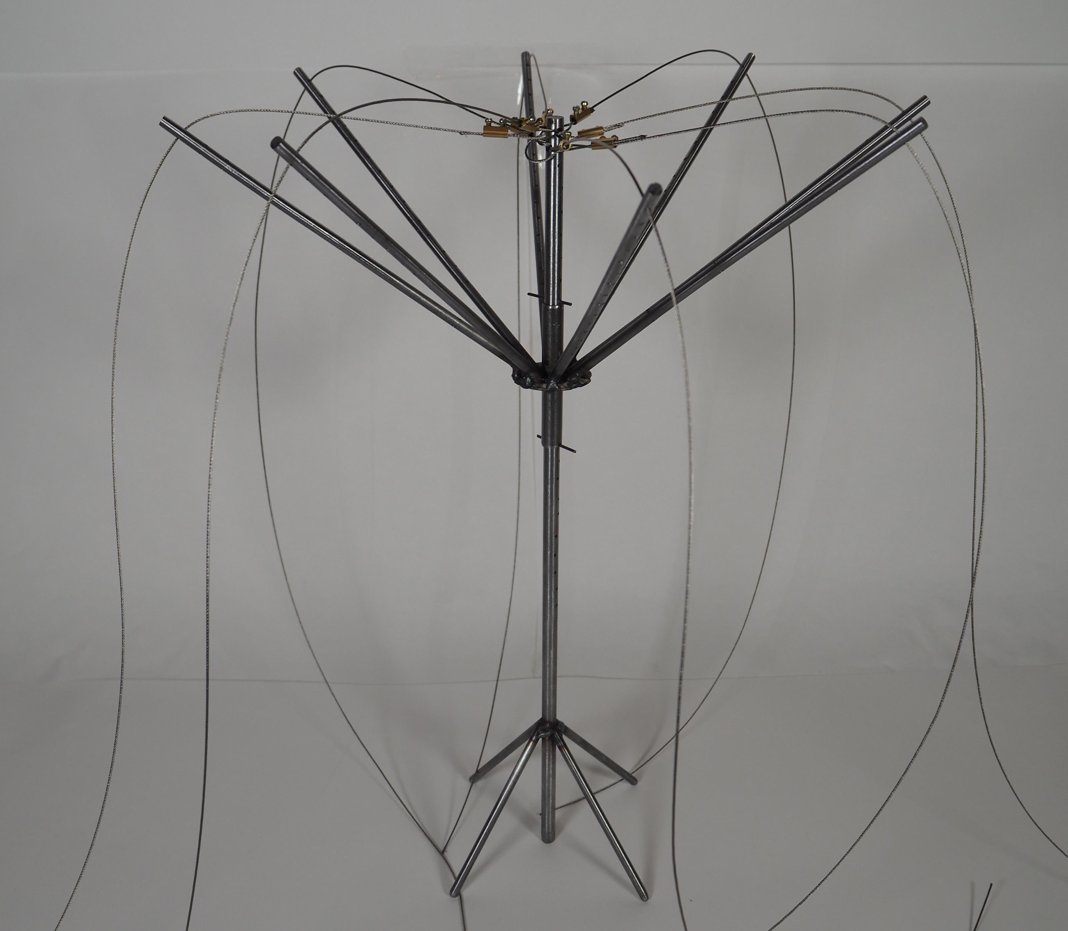
Steel system to hold the membrane from within by using the water pressure pullingin all directions.
1:4 Axonometric
Steel cables Attached to the central core, goes through the rods and is xed onto the membrane diafragm
8 arm spanning system Recieves steel cables that go from main pole to membrane.
Sliding mechanism
Movable type to ajust to di erent shell heights
Central Pole Recieves most all stresses
Latteral stabilisers
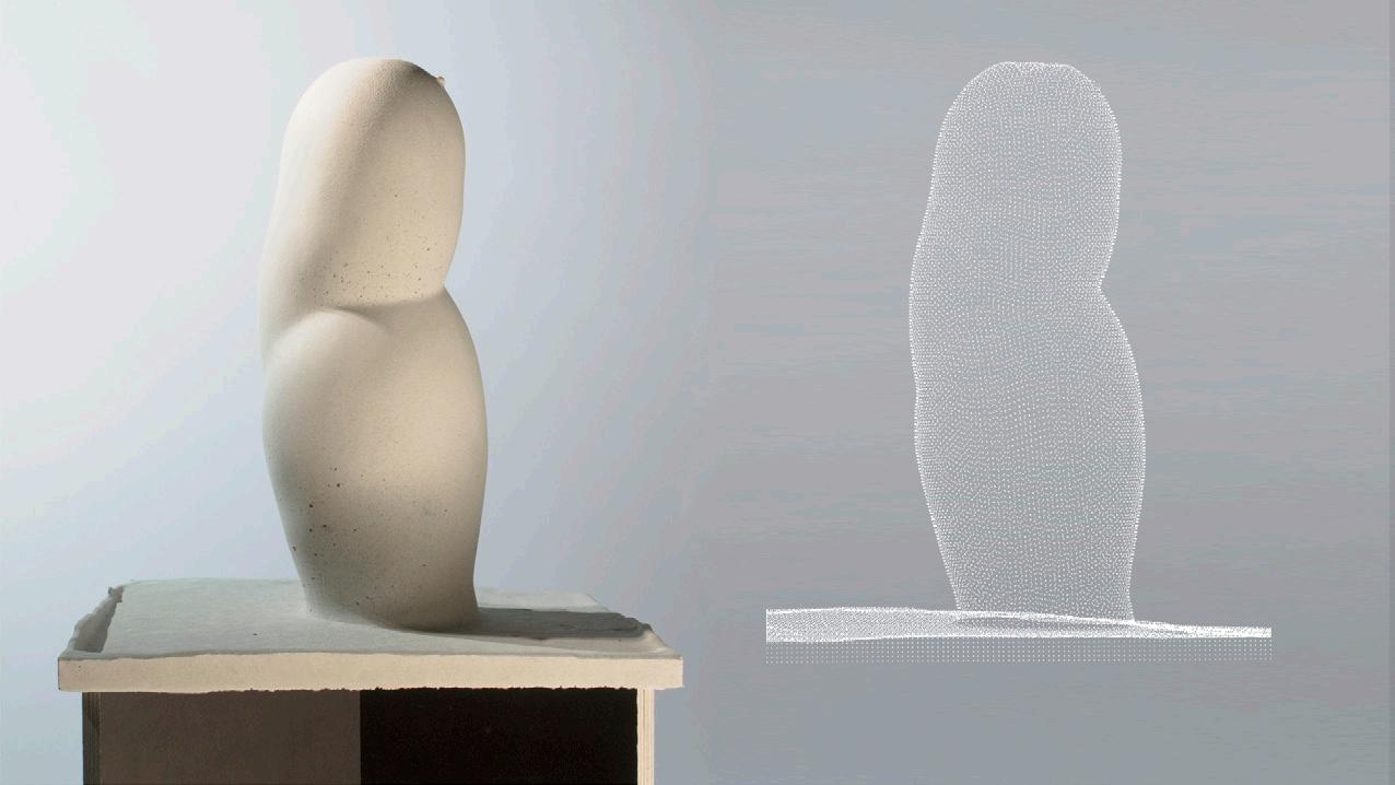
Tool to produce a 1:25 shell model using once again 7 layer natural latex with a larger body of water to trigger more stretching.

Steel self supported structure
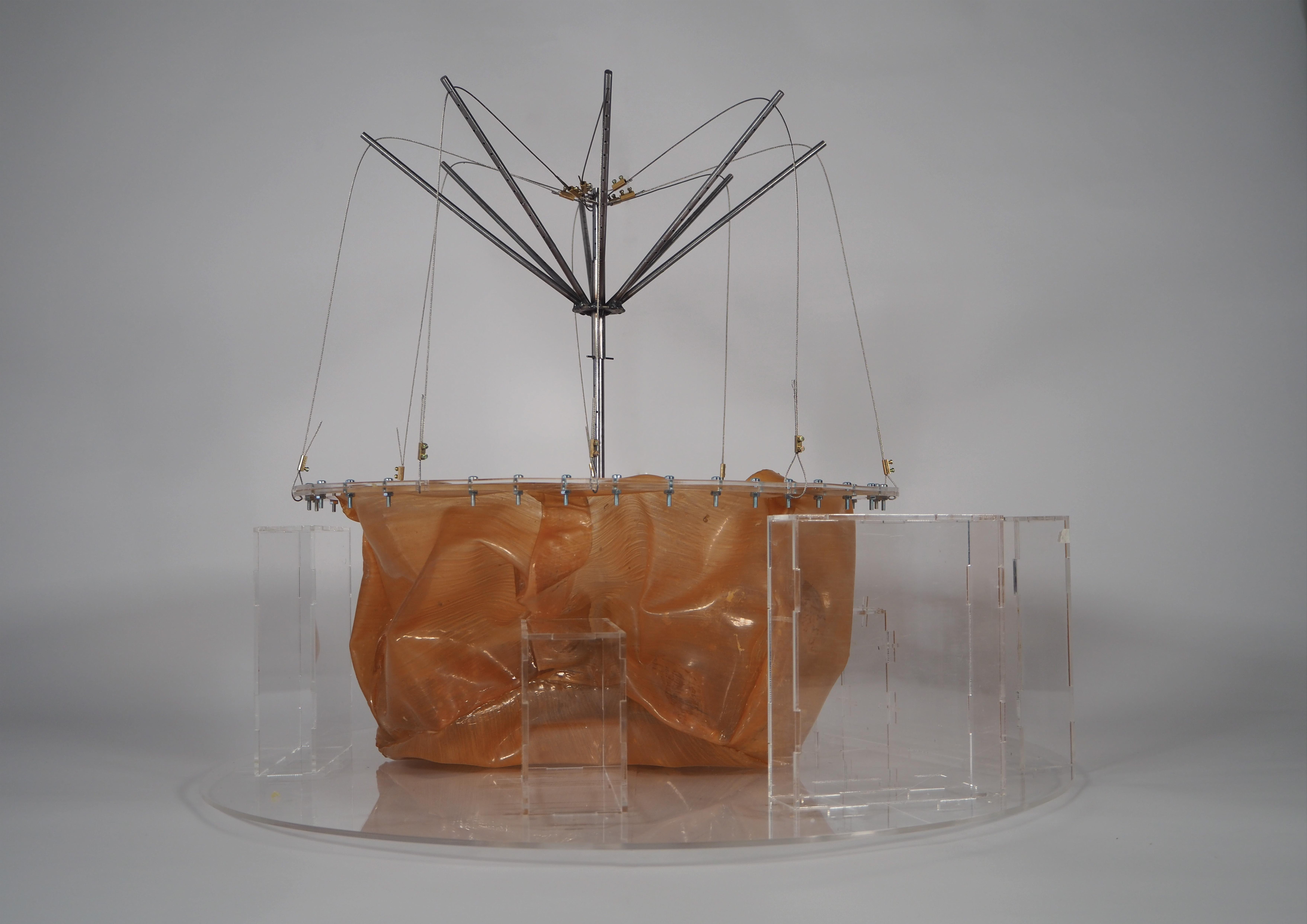
Ajustable steel wires
Diafragm
Natural 7 layer latex membrane
Falsework formers

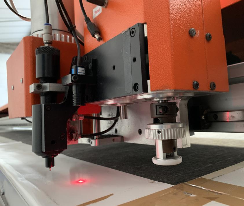
High frequency welding is a manufacturing process where two plastic parts are welded together using an electromagnetic field. The resulting join can be very strong – often close to the original strength of the materials joined. In some scenarios the weld can be even stronger than the original materials.
Using a high frequency electromagnetic field, the material is heated and pressure added to melt and fuse the two materials together. No outside heart is applied. Instead the heat is generated within the materials. During cooling (under continued preassure), the materials are fused together and a weld has been created. This results in a very strong bond between the two parts.
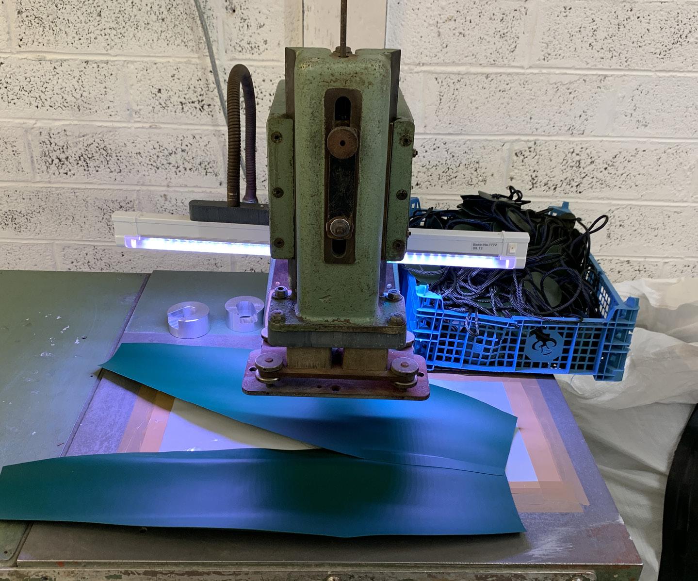
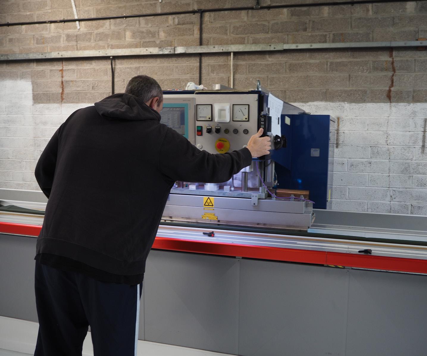
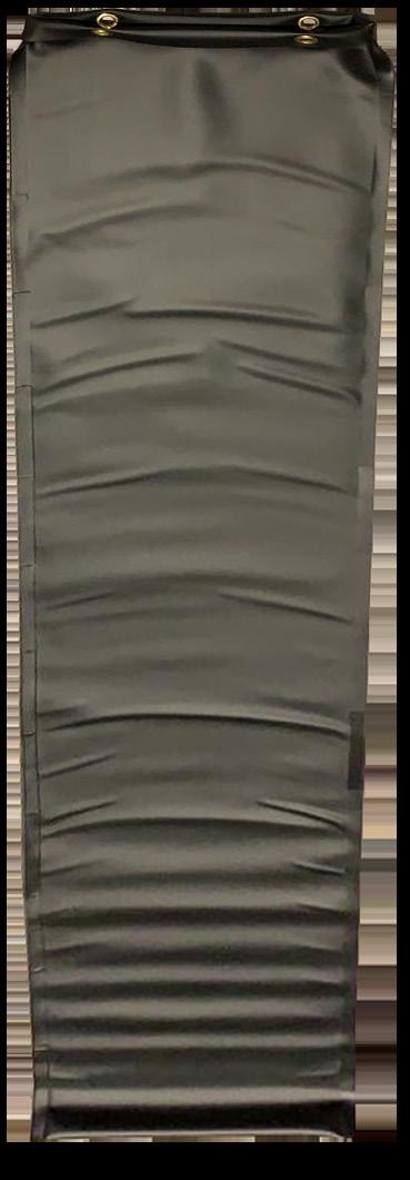
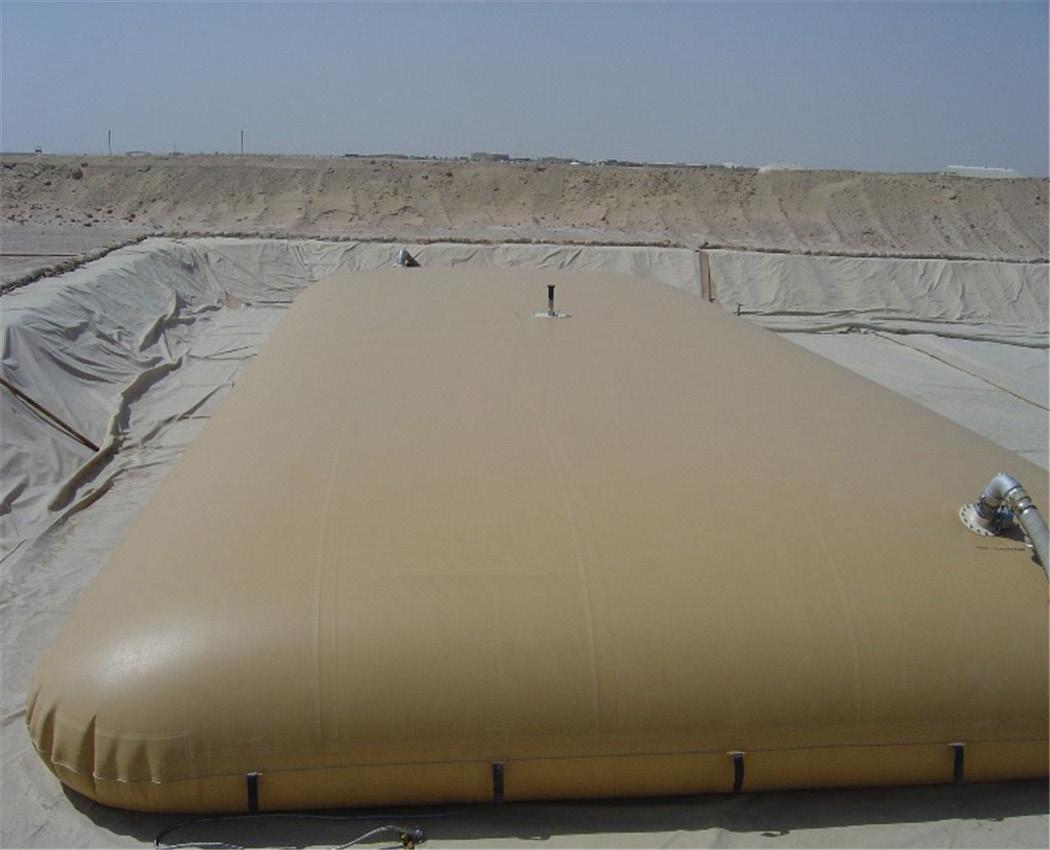
RIFLEX bag succesfully contained 150L of water.
The bottom buldged more than the rest due to high pressure and no stitch pattern control.
Ri ex non reinforced PVC bag material and welded joinery test
Assembled at Outsourced Manufacturing service Ltd, Bristol
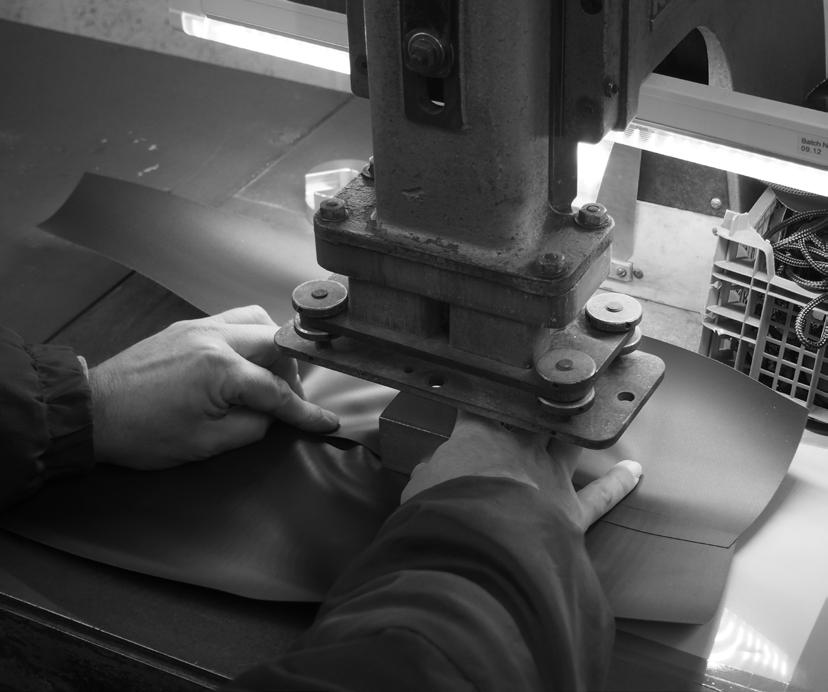

PVC is not an elastic material but is still flexible, when under a lot of water pressure the material can stretch
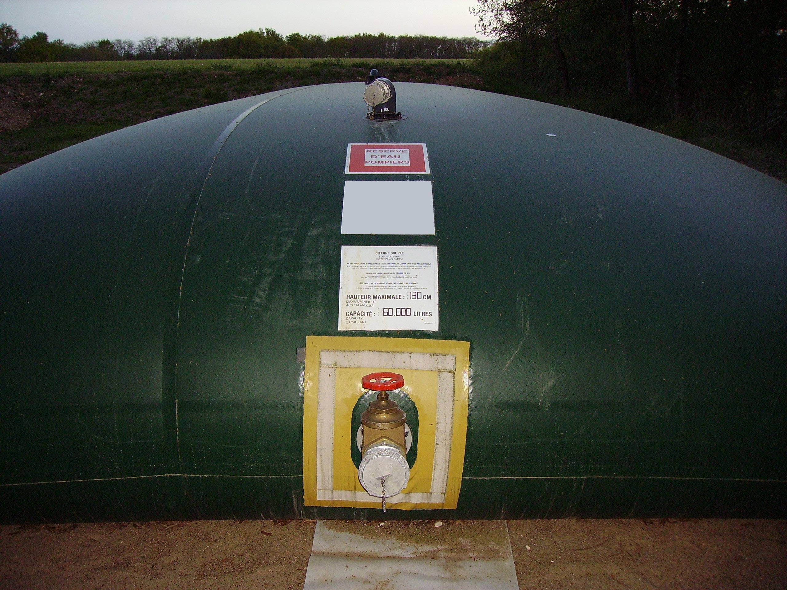
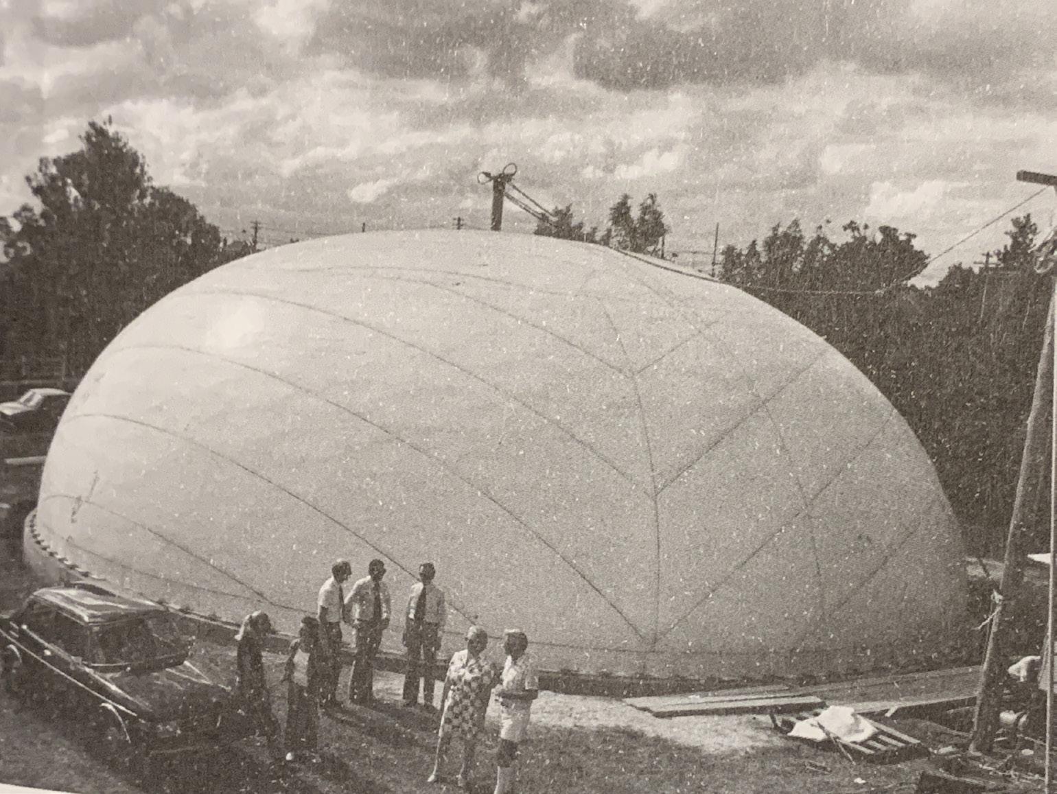
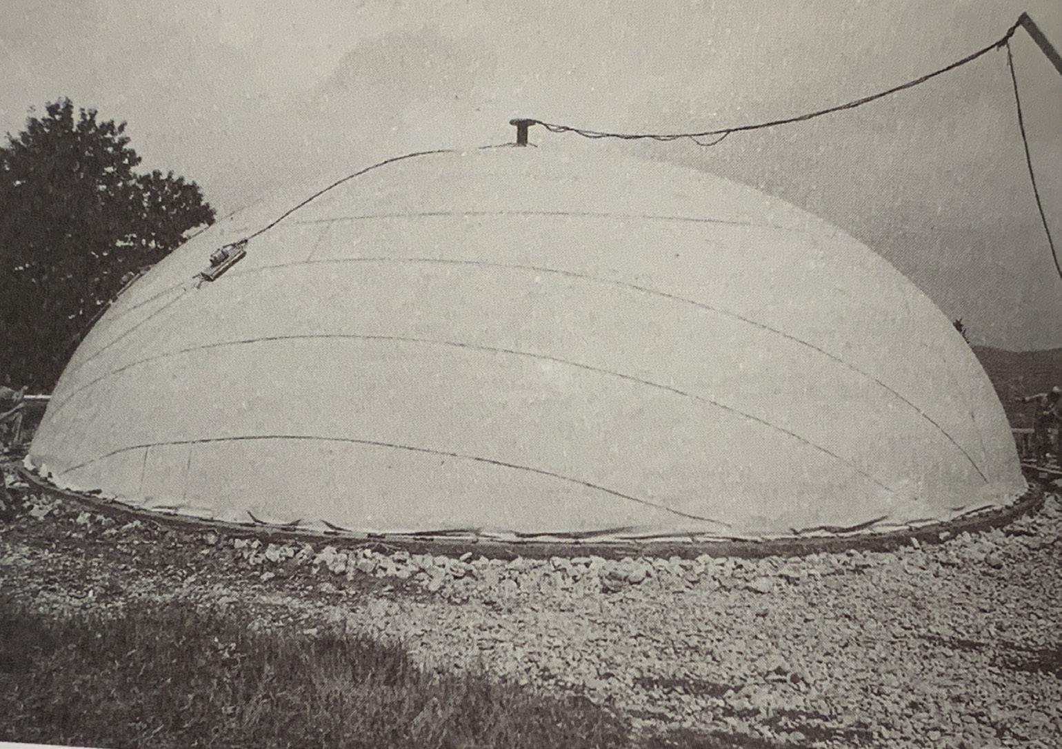
PVC patches welded together to form a dome membrane. Rebar is pre-installed flat on the ground within tension springs and concrete is casted over, then another layer of PVC is added on top to seal the concrete in and the most inner air pocket created is inflated and the concrete is lifted into a perfect dome shape until it cures.
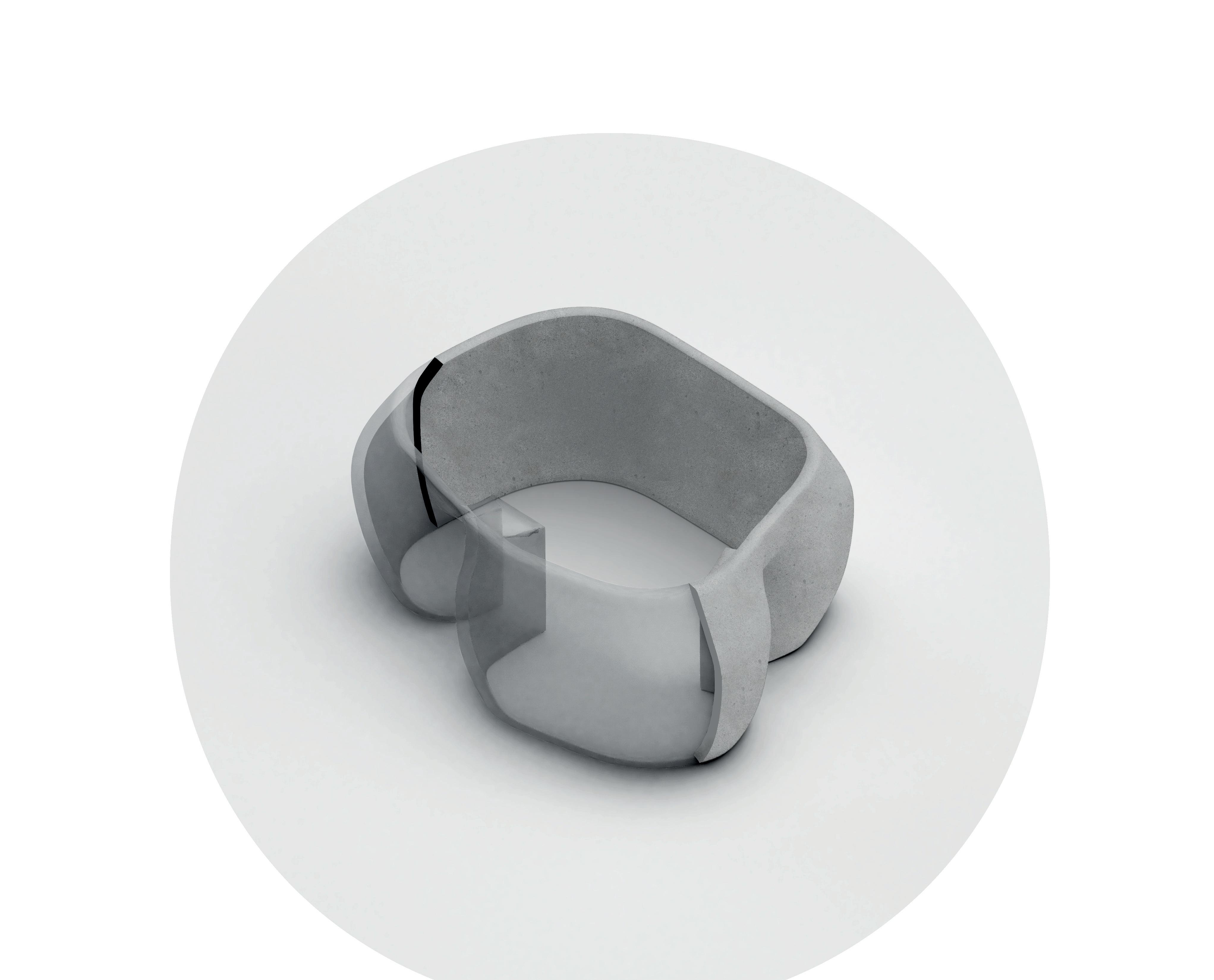
The Formers. 4
A series of modules are designed to the of a footstep and its is the smallest architectural impression it will leave. They act like pixels and can be re-organised in many different way to press shape and function into the shell wall freeing formwork and will be reused after casting for another one or scattered on site to inhabit the site under different forms.
Retaining wall fragment 1:25
Repeat the same sequence until fully disassembled
Step 6 remove lower second row
Step 5 remove upper second row
Step 4 remove joints 1.1.1
Step 3 remove rst row
Types of modules: forces they react to within the matrix - 1:10
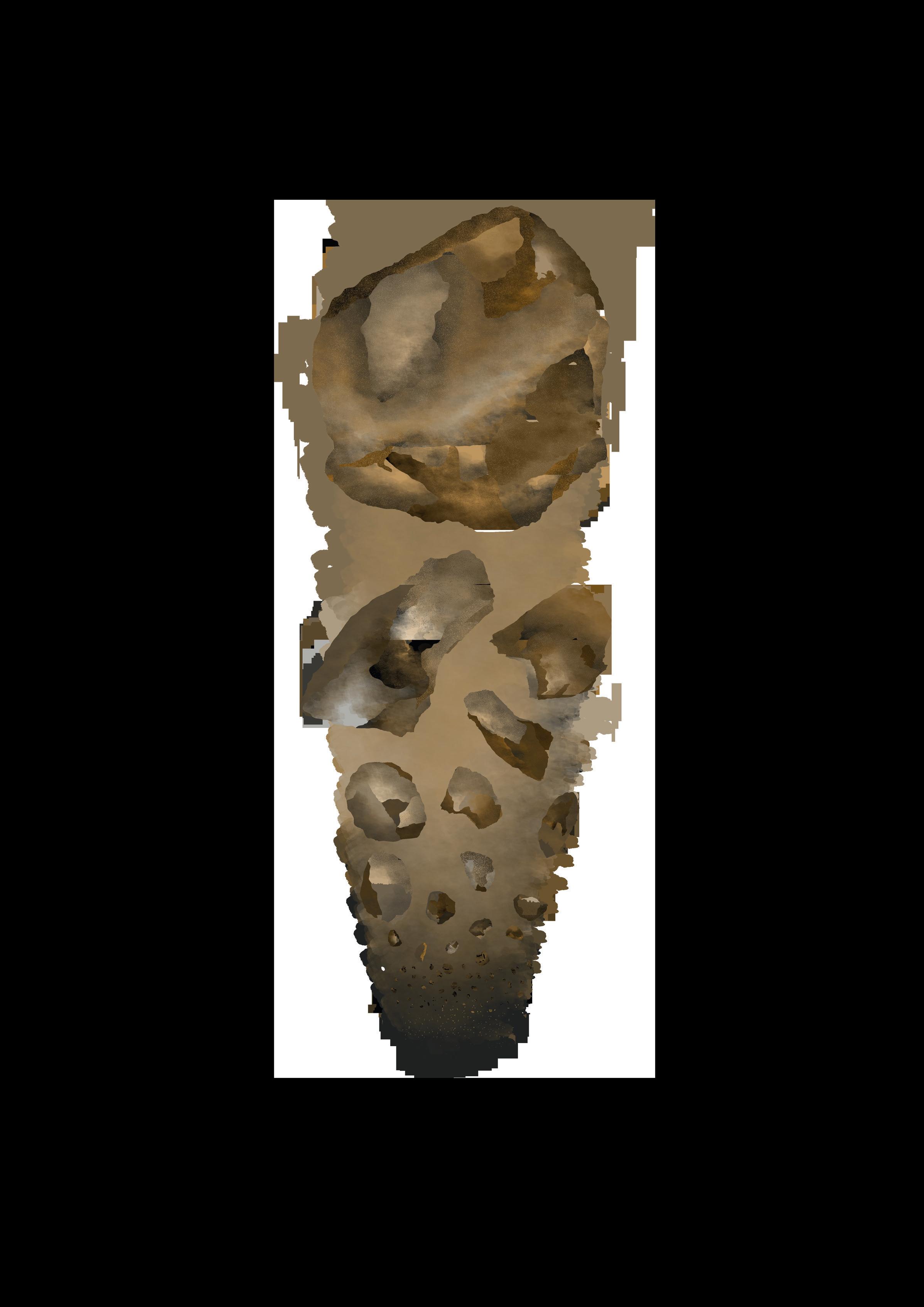
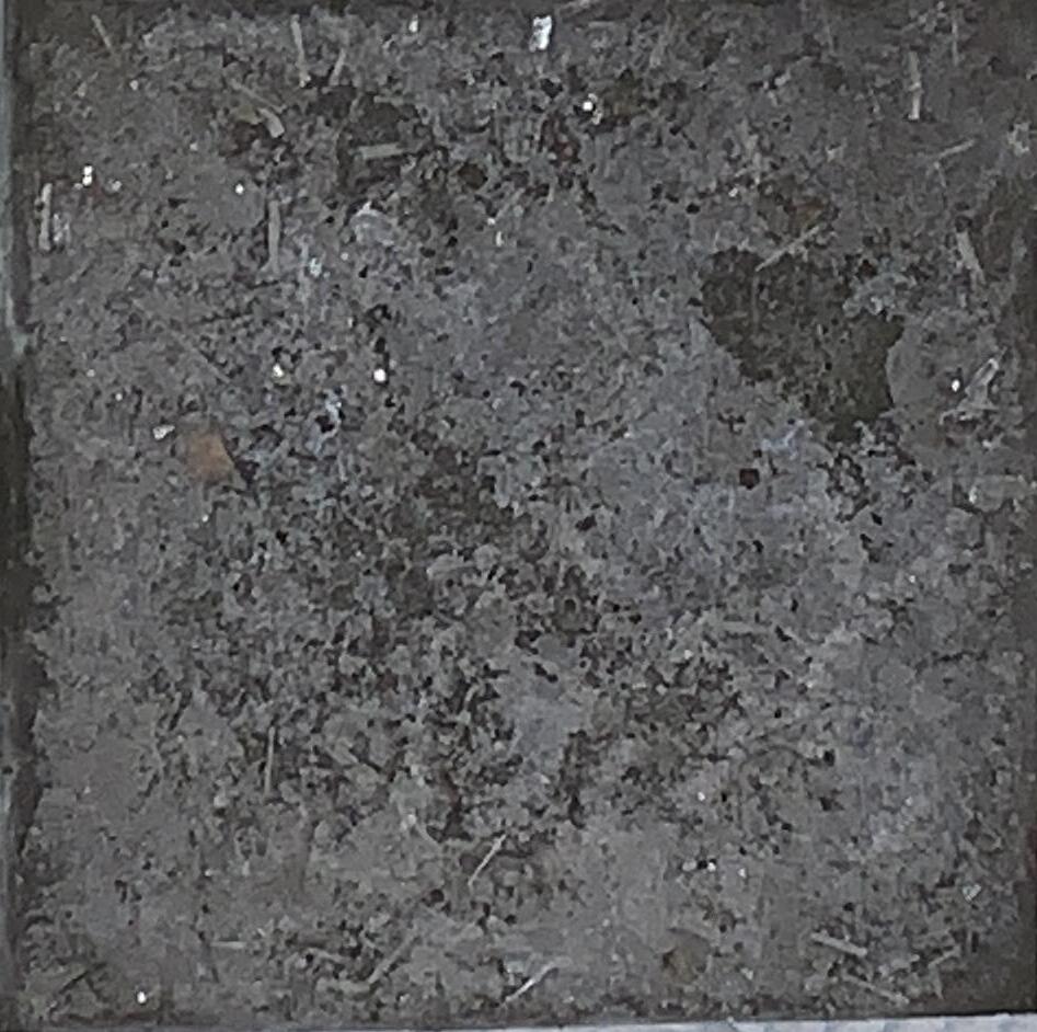
Ice fragments
Shell Fragment Fromwork / Falsework
Here is a base retaining wall arrangement simply to control the propagation of the water vessel. The addition of more modules in di erent con gurations can create fonctional impressions into the ice, giving the shells integrated fonctionalitys.
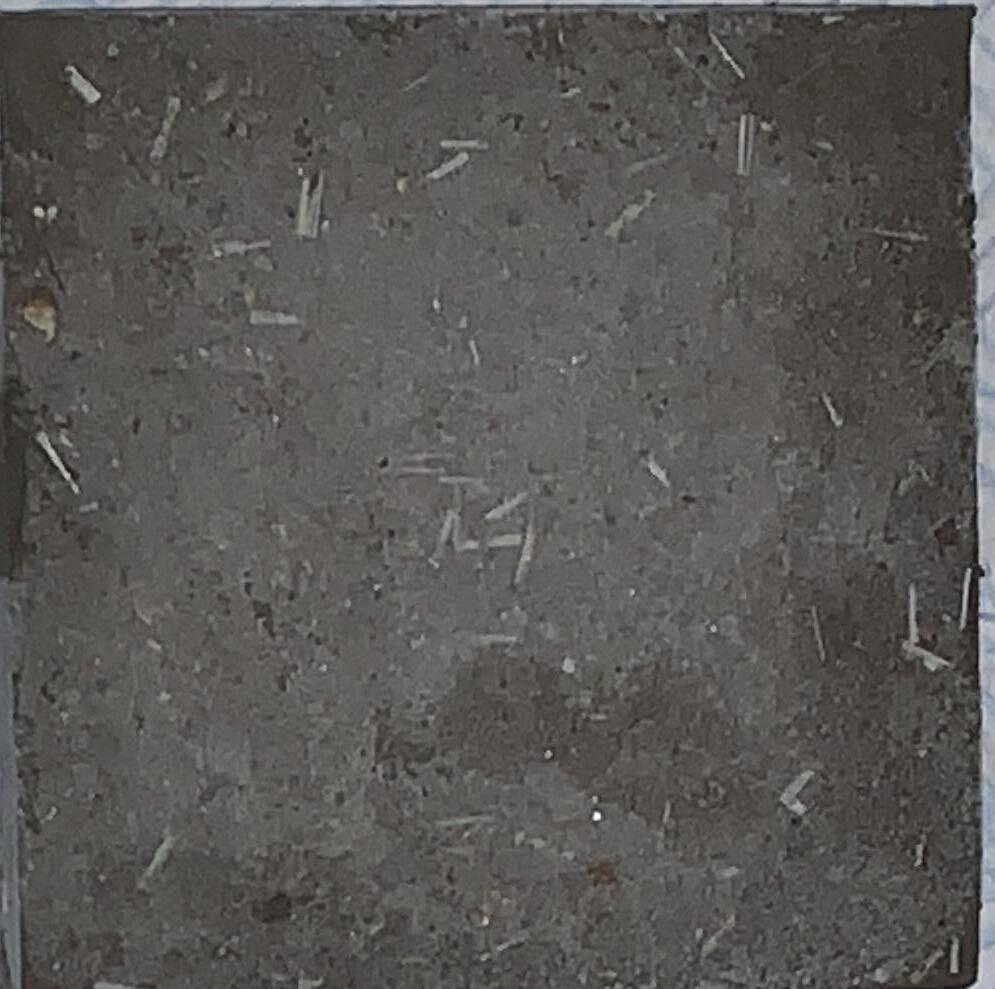
Ice fragments
Shell Fragment Fromwork / Falsework
The modules are interlocked to produce a self standing negative staircase, that acts as a retaining wall when the Pvc bladder is lled with water. That high pressure creates the double curvature of the shells, and enables the vessel to capture the imprint of the asework.
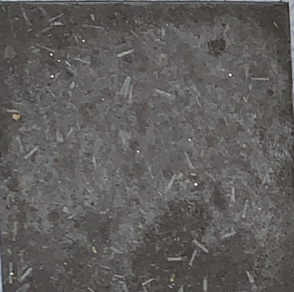
Ice fragments
Shell Fragment
Fromwork /
Ice fragments
Shell Fragment
Fromwork / Falsework
Ice fragments
Shell Fragment
Fromwork / Falsework
Technique.
Exploration of concrete, shotcrete application and different mix testing for ice curing.
Timeline of the development of concrete
The history of concrete is closely in entangled with the development of its formwork
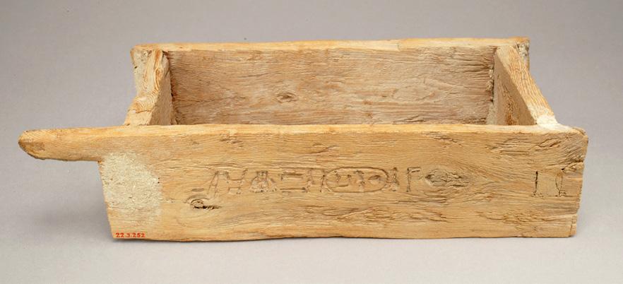
First known formwork clay bricks formed in wooden forms
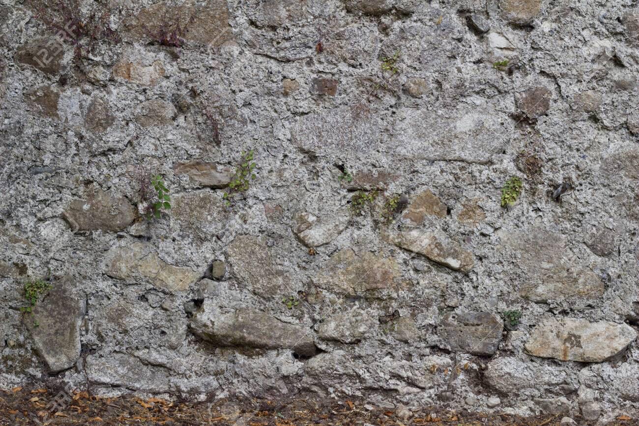
Greeks began constructing in an entirely manner: Instead of stacking bricks and mortar they developed the technique of cast masonry called Emplecton
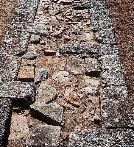
Two wall shells made of ashlar or wooden boards were used as formwork, quarry stones of different size were placed in between and doused with lime mortar as binding material.
The Greeks used lime as binding material, and the Romans developed this further by changing the composition and creating the first permanent binding material.
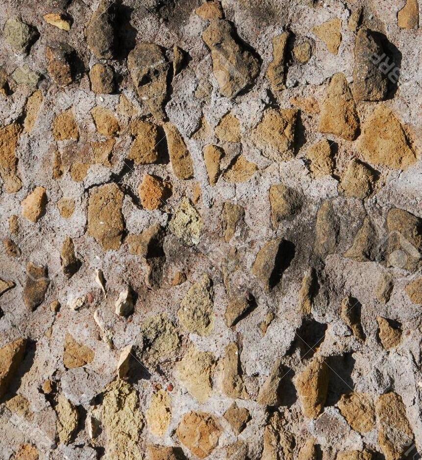
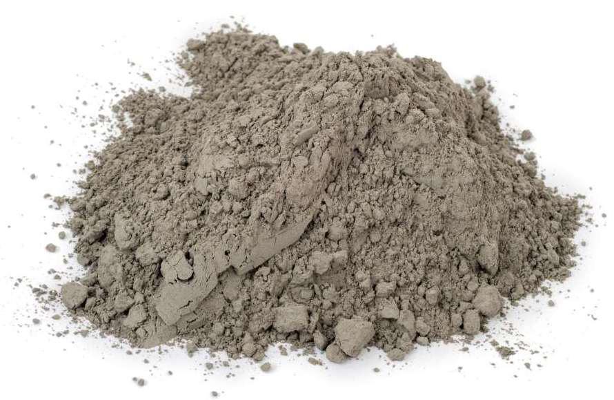
They burned lime and added powder-shaped Puzzolan (natural stone- predominantly volcanic ash), sand and crushed rocks and water which resulted in liquid stone.
This was called Opus Caementitium and was the first type of concrete which was also able to harden under water.
The consistence of Opus Caementitium in buildings today can be considered similar to those of approximately 2,000 year ago. With the collapse of the Roman Empire the knowledge of Opus Caemen- titium vanished.
-For almost 1,500 years Opus Caemen- titium remained unused until the transition from Renaissance to Baroque
In the 17th century alternatives for wood and clay buildings were wanted and the binding material Trass was developed. This was the basis for further research on what we call cement today. As a consequence, formwork was reintroduced, and for example St. Peter’s Basilica in Rome was built.
The main innovative steps in concrete technology have been made after the Second World War, especially during the 1990ies. Major developments were the five component system and the use of modular framework.
18th Century
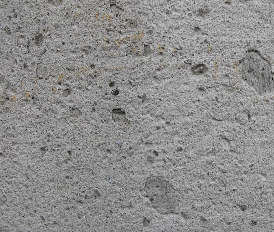
British engineer John Smeaton re-discovered a material composition which did not only harden when exposed to air but also under water.
This new binding material was named Roman cement’. Sand and crushed rocks were added to cement for the first time, the result being named concrete
19th Century
Again in Great Britain, a building contractor from the city Portland harvested clay and limestone from natural resources; burned them together and then ground the result, thus developing Portland cement for which a patent was applied in 1824. These were the beginnings of the product as we know it today.
Frenchman Joseph Monier is considered to be the inventor of reinforced concrete
Monier formulated the fundamental idea to place reinforcement in those areas where the final concrete structure is subject to tensile loads.
Austrian industrialist Ludwig Hatschek added asbestos fibers to cementitious material and registered the patent for Eternit in 1900.
A major improvement was established in 1971: glass producer Pilkington Brothers Ltd. (England) offered glass fibers to the concrete industry as a material. This was the official begining of fiber reinforced concrete.
20th Century
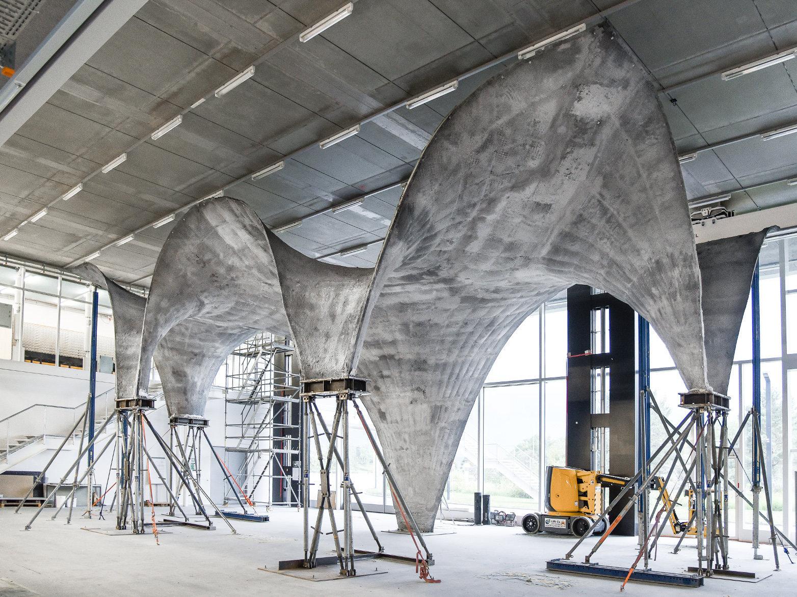
The capabilities of concrete were improved further by the invention of high-strength concrete. This type of concrete has higher initial strength and is thus able to stay in place on a curved formwork which enhanced the possibilities of shell structures.

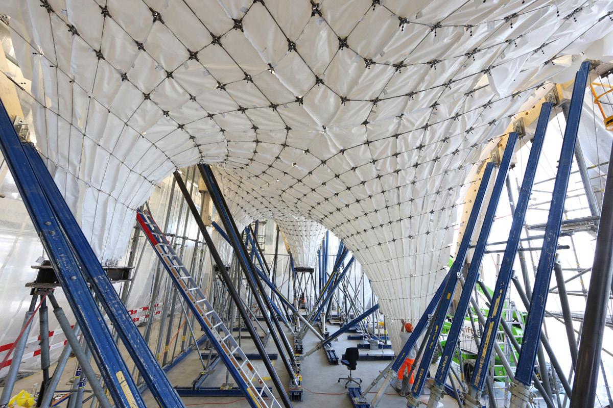
Concrete producer Dyckerhoff and Widmann developed shotcrete to apply it on to shell formwork. This development established the era of concrete shell structure.
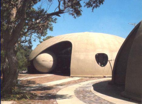
The most relevant representatives are Pier Luigi Nervi (since 1925), Felix Candela (since 1950), Heinz Isler (since 1950) and UlrichMüther(since 1964).

Types of concrete
Various concrete products have been developed over the last 25 years. Major developments were the five component system and the use of modular framework.
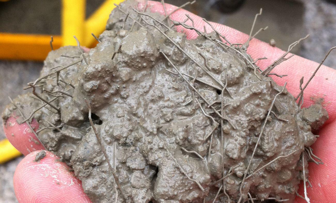
In order to replace other types of concrete reinforcement, steel, glass or plastic fibers can be added to the concrete.
The properties of the resulting fiber concrete are mainly defined by its mechanical properties and geometry, the quantity of added fibers, their orientation, the manufacturing process and the bonding between fiber and concrete.
Technical textiles such as glass or carbon fiber are used in the form of meshes, thus the name textile- reinforced concrete.
The main advantage of using textile as reinforcement material lies in the fact that the reinforcement does not or minimally need to be covered-in contrast to steel reinforced concrete-since textiles do not corrode.
SCC is very viscous and self-compressing. This is achieved by an increased powder content and specialized flux material.
Compacting the concrete by vibration is not necessary, saving time and money for related processing steps, while the surface is clearly more appealing than that of conventional jolted concrete.
Due to its aeration properties and extraordinary flow characteristics, SCC is especially suited for elements with a high share of reinforcement and free formed geometries.
Ultra-high-performance concrete possesses an especially high structural density and thus an extremely high compressive strength.
The major advantage is its higher loadbearing at lower material thicknesses.
The water concrete ratio is reduced and high-performance plasticizer (PCE) as well as admixtures like Silica-fume and fly ash are added to achieve these characteristics.
. Lightweight concrete is particularly characterized by its low weight and low heat conductance and therefore good insulating properties, in comparison to standard concrete.
The stone aggregate of dense light-weight concrete owns a clearly slighter cohesiveness than standard concrete. Thus, considerable weight savings in this case.
In spite of its compressive strength, ultra-light-weight concrete can still not to be used as structural concrete today.
DUCON is a brand cro-reinforced mance concrete. it was developed explosion and concrete.
This concrete sand, self-compacting tar and a micro-reinforce ment, whereby ductile and therefore absorbent.
DUCON offers spectives for the tural vocabulary a realizable component thickness of> optional cross
brand of micro-reinforced high-perforconcrete. Originally, developed for an bulletproof consists of self-compacting mormicro-reinforcewhereby it becomes therefore energy
offers new per the architecvocabulary as it has component 10 mm and sections.
Types of concrete that minimize the inescapable environmental pollution of its production.
The approach is to reduce the cement share while maintaining flowability, processing time span, durability and consistency.
Thereby greenhouse gases can be reduced by 30 to 70 %. Environmentally friendlier admixtures such as slag sand, fly ash and pulverized limestone are used to reduce the percentage of Portland cement.
This is a mixture in which cement functions as binding material between concrete and photocatalysts such as TiO.
Thereby a reaction on the surface of the building block occurs between the photocatalyst and aerial nitrogen oxide which results in nitrite / nitrate bound on the surface.
Daylight is all that is needed for the process. This bears advantages especially in big cities where the NO as acid corrosive gas has reached partially unhealthy dimensions.
Up to 10% can be absorbed. In addition, the surface treatment positively affects the temperature, relative air humidity, and radiation intensity.
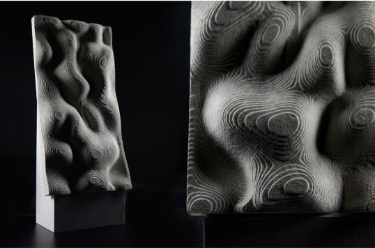
Especially developed webbing made of slightly conductive glass fibers is added to the concrete.
The fibers account for approximately 4% of the material.
The fibers are not added to the fine concrete mix but rather deposited into the formwork layer by layer.
The slightly conductive glass fibers allow us to see light, shade or even colors through the concrete.
Nowadays, this material is not only used for internal applications but facades as well.
The idea of Breathable Concrete or Air Permeable Concrete (APC) was originally invented for the purpose of developing dynamic insulation for buildings.

Current experiments on the material show that APC is 24 times more permeable than traditional concrete.
However, there are still limitations on how far the material can be taken as a structural material since permeability leads to unacceptable losses in strength and structural integrity.
With regards to recyclability and CO, reduction, Building parts are developed that adapt their material properties exactly to local requirements.
Thus, in areas with higher insulation requirements more aggregate is added, resulting in lower density, than in load-bearing areas with a significantly higher density.
The information about the amount of aggregate to be added is led directly from the computer based on structural calculations.
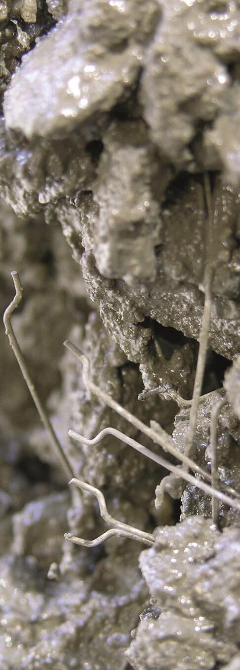
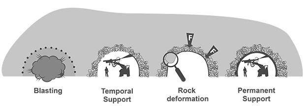
Shotcrete is used in mining and tunnels (ex: Tube in Sweden), it is automated through he use of a robotic arm that pneumatically sprays steel fibre reinforced concrete on a surface making it thicker and ticker in layers. It can also be reinforced with additional steel rebar High performance concrete is used mixed with fast setting and antifreeze mixtures in order to cure and harden quickly.
of sharp sand

of frostproofer
Result: Experiment failed, proper concrete hydration not successful. frostproofer was not suitable for temperatures lower than -4°C and starndard concrete was used.
Water froze in the concrete, proper curing not succesfull.
The use of 6% calcium nitrate in a high preformance concrete mix should permit proper hydration.
Result: Experiment failed, proper concrete hydration not successful. frostproofer was not suitable for temperatures lower than -4°C and starndard concrete was used.
Result: Experiment failed, proper concrete hydration not successful. frostproofer was not suitable for temperatures lower than -4°C and starndard concrete was used.
Water froze in the concrete, proper curing not succesfull.
The use of 6% calcium nitrate in a high preformance concrete mix should permit proper hydration.
Water froze in the concrete, proper curing not succesfull.
The use of 6% calcium nitrate in a high preformance concrete mix should permit proper hydration.
Still no curing
Slight change in colour
Up
Significant change in colour almost cured
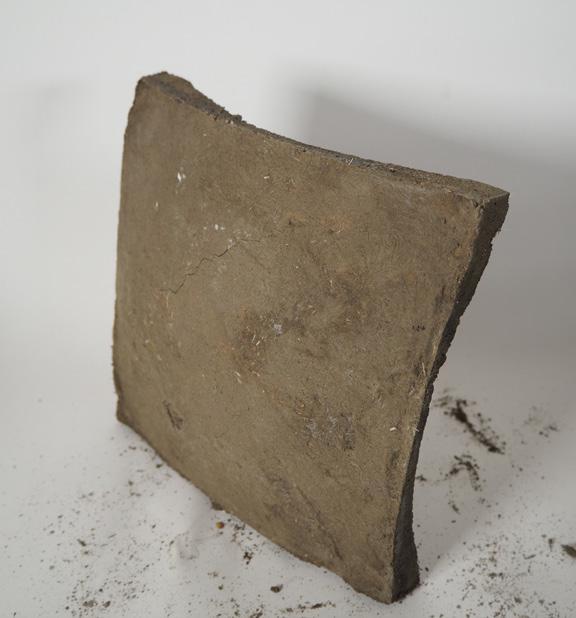
Concrete curing test :
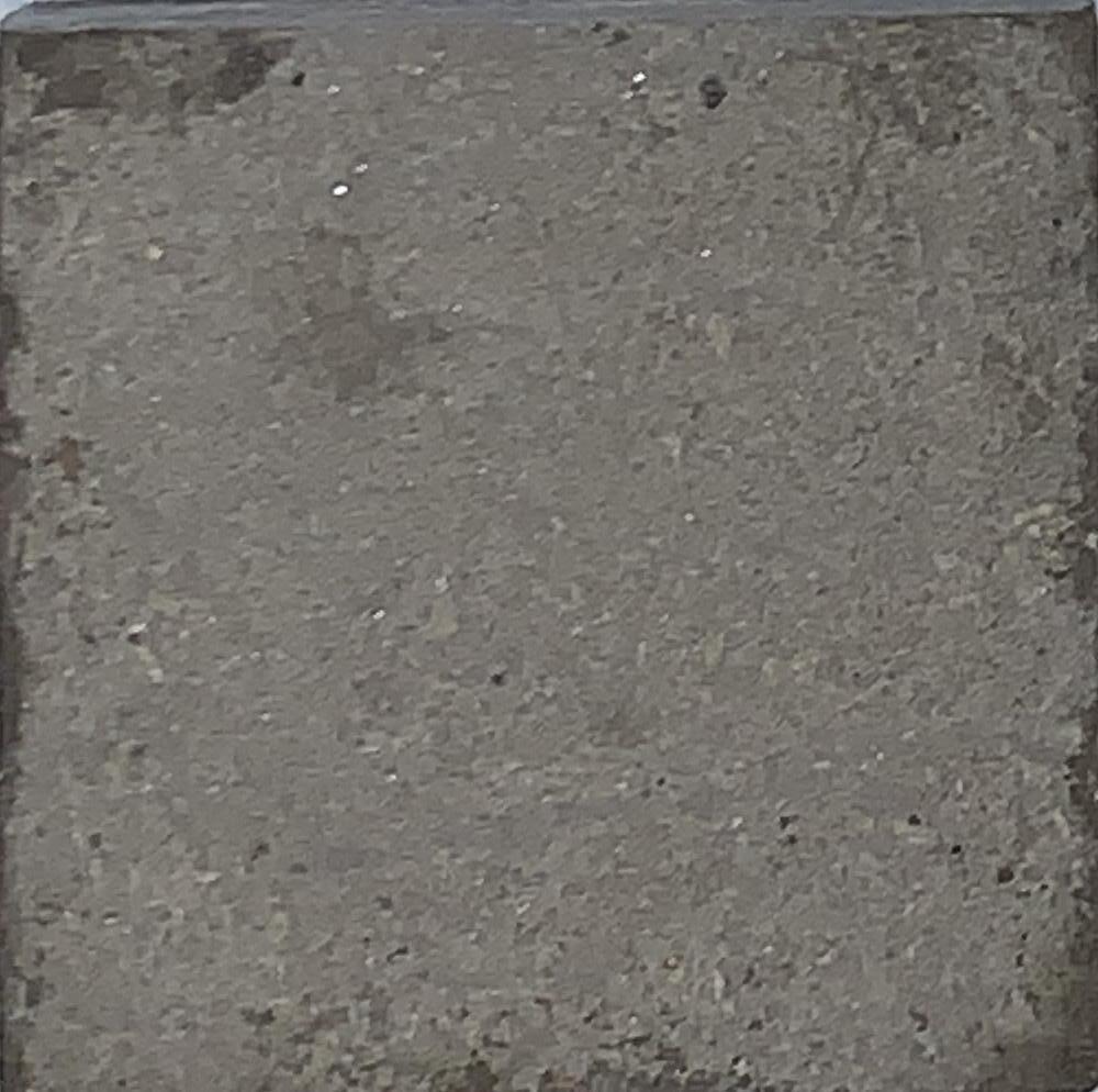
Duration in freezer: 1 week
Temperature: -10 C
Sand/cement/fibreglass ratio: 2/1/0.5
Type of cement : Fast setting
Curing
Slight change in colour
KTH Royal Institute of Technology, Osquars
Ice blocks are manufactured visa artificial cooling are ten placed inside of a freezer housing a cnc machine.
Formwork is milled into the ice at a low temperature of -20 C.
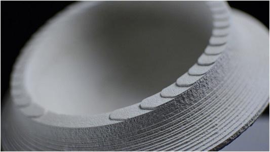
UHPC concrete mixed with antifreeze added mixtures is then poured at the same temperature as the ice into the formwork without any separating layers. The temperature have to match so that the ice does not melt and deform.
After 5 days of curing the ice containing the concrete can be placed at room temperature and self demould leaving the concrete cast.
This ice allows one to make complex shapes without any uncasting difficulties
5, 10044 Stockholm, Sweden
Deployment. 5
Construction sequence Plan
Ice core
After a few weeks, the ice core is formed and the solid formwork is ready for casting.
PVC Membrane
The shape of the membrane is fixed now that the ice core is formed, modules are demolded and their imprints remain.
Concrete Layering
A series of thin layers of HPC concrete with ad mixtures are sprayed onto the shell surface; once that layer hardens the folowing thick layers of concrete can be applied indepentently of the ice core.
Shotcrete application
The concrete is pneumatically projected at a high velocity onto the formwork via a robotic movable shotcrete machine.
Water drainage
Once the concrete has set and the winter season is over the ice core will melt naturally and self demold, draining back to the lake to be reused for the construction of a next shell.
Deployment Plan Iteration 1
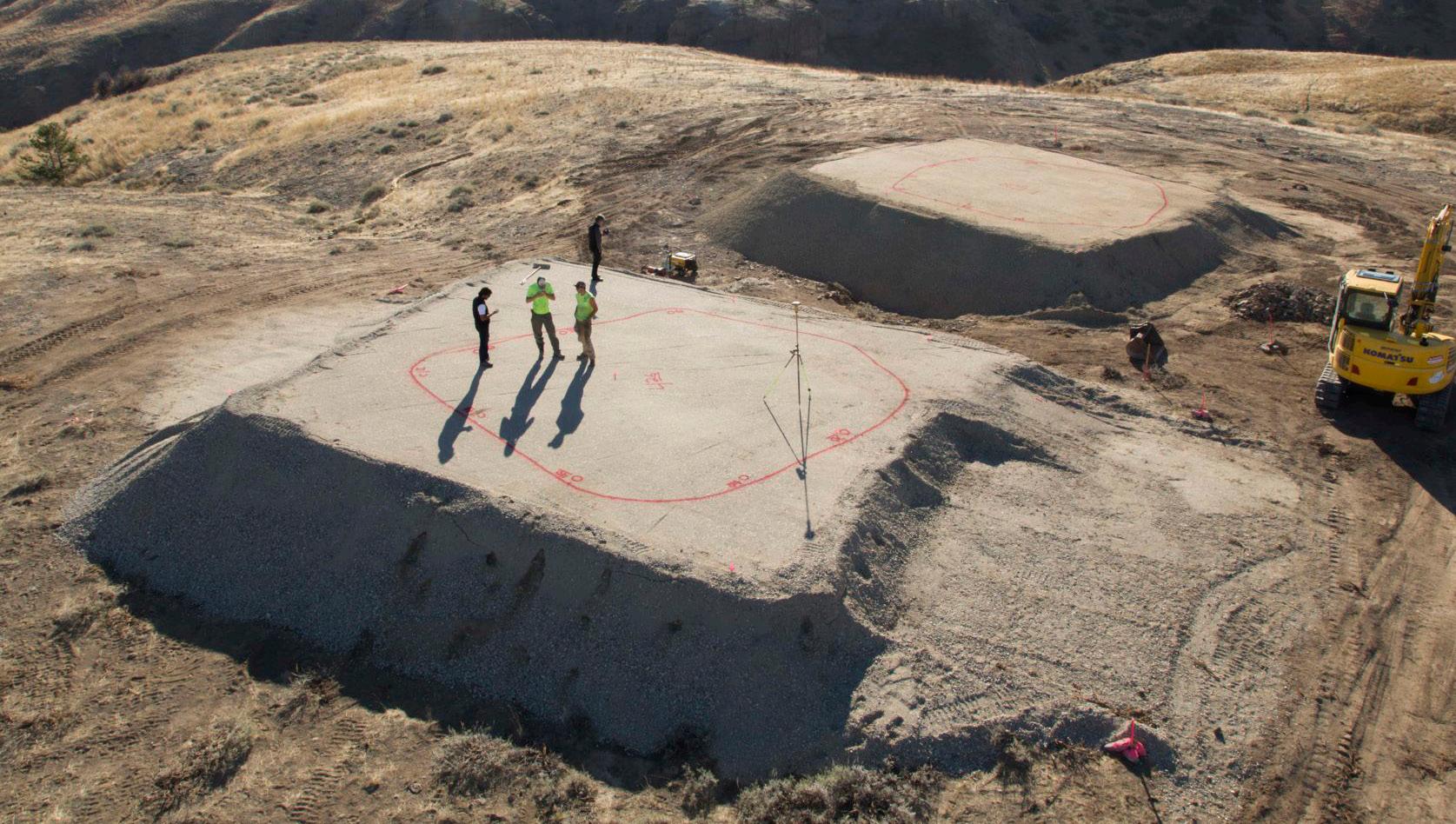
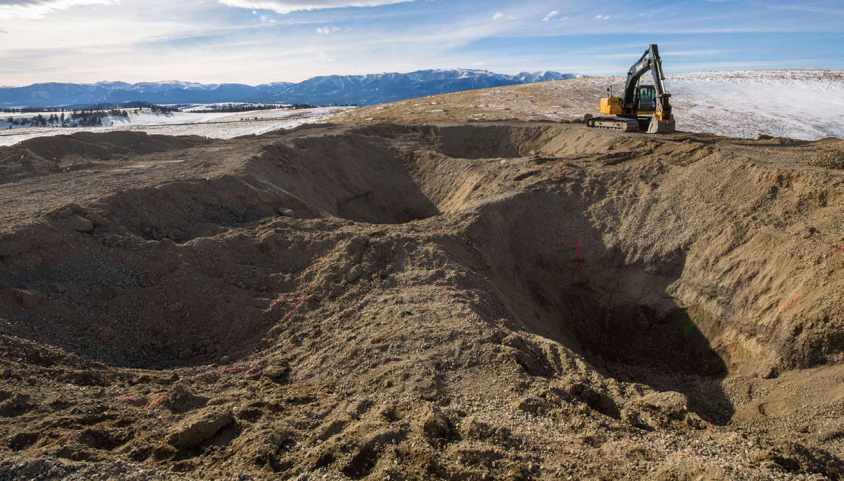
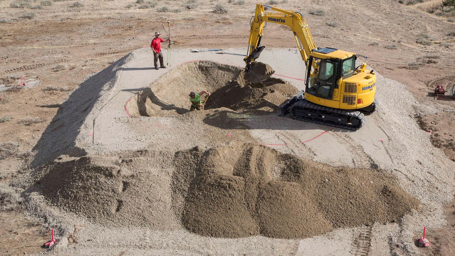
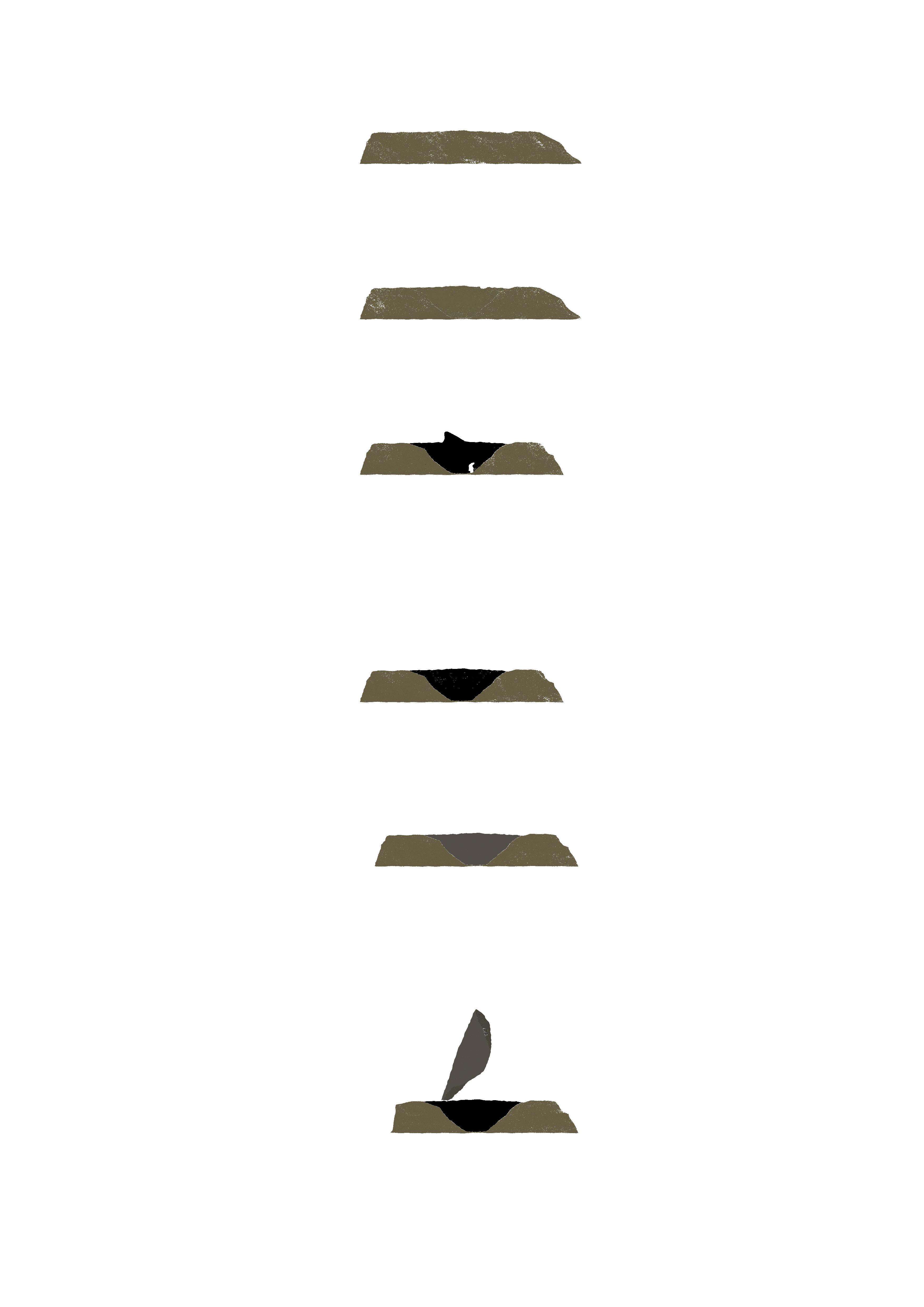
The project takes places with water at its epicentre. First a lake is excavated before the winter season. Then the drainage gutters are dug depending on the predetermined position of each shell.
At the start of the season natural rainwater is collected and the surface freezes one its is cold enough conserving the water underneath at low temperatures. The modules and membranes are then brought to site in containers and are assembled according to instructions. A slit is cut into the lake surface and the collected water is pumped into the membranes that will take their final form due to the module arrangement placed around it and the immense water pressure build-up. After a few weeks, the ice core is formed and the modules can be removed as their pressures and traces are captured and temporarily frozen in time. Thin layers of UHPC steel fibre reinforced concrete with antifreeze additives are then applied to the surfaces in this layers to obtain a solid base layer, then the rest of the concrete can be applied and rebar grids can be introduced if necessary. At the end of the winter season when temperatures rise enough the ice cores will melt away, the water will flow back to the lake and the concrete shells will remain standing and on it all the absent traces of its formwork.
1. There is the absence of the water pressure and gravity that formed the shells
2. There is the absence of the modules that manipulate the behaviour of the vessel and leave their functional imprints on.
3. There is the presence of the modules scattered around the project organised as different forms to serve different functions.
4. There is the presence of water in the guttering system coming from under each shell that was left embedded in the ground for initial drainage.
Conclusion
Overall my technical studies shave been helpful in understanding the properties of different materials as formwork specifically water that was chosen for its exceptional properties and gravitational behaviour. I acquired an understanding of how such a technique would be preformed at a 1:1 scale and the ability to manipulate theses high pressure to my advantage as a way to emphasize the presence of absence in the project. The formwork consists contradictory geometries that come together in a very interesting way giving more freedom to formwork while still respecting ergonomic al norms.
Theses studies have been driving my project and fuelling my ambition to add an other layer of experience to architecture through presences and absences triggering association in people experiencing the space making them imagine the construction sequence.
The next step would be to test it at a larger scale with actual concrete/ice application as well as the deployment of this technique on site with water at its epicentre. This will introduce the inter relation between the shell inhabitable cores, enclosure and site.
1:2 Axonometric
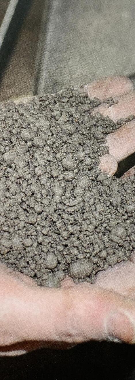
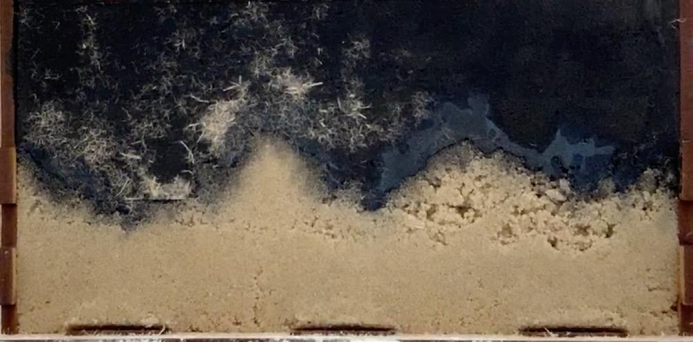
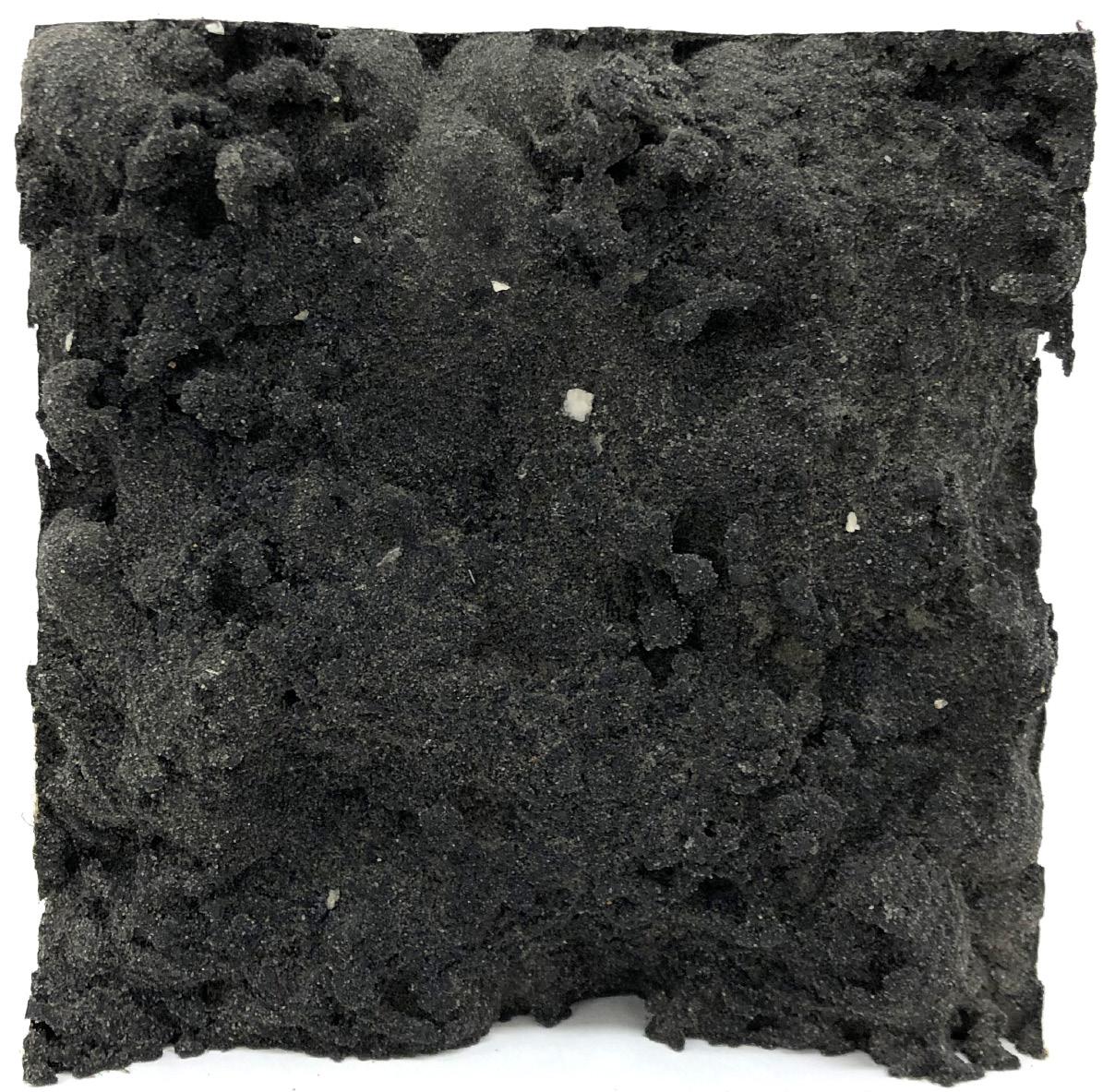
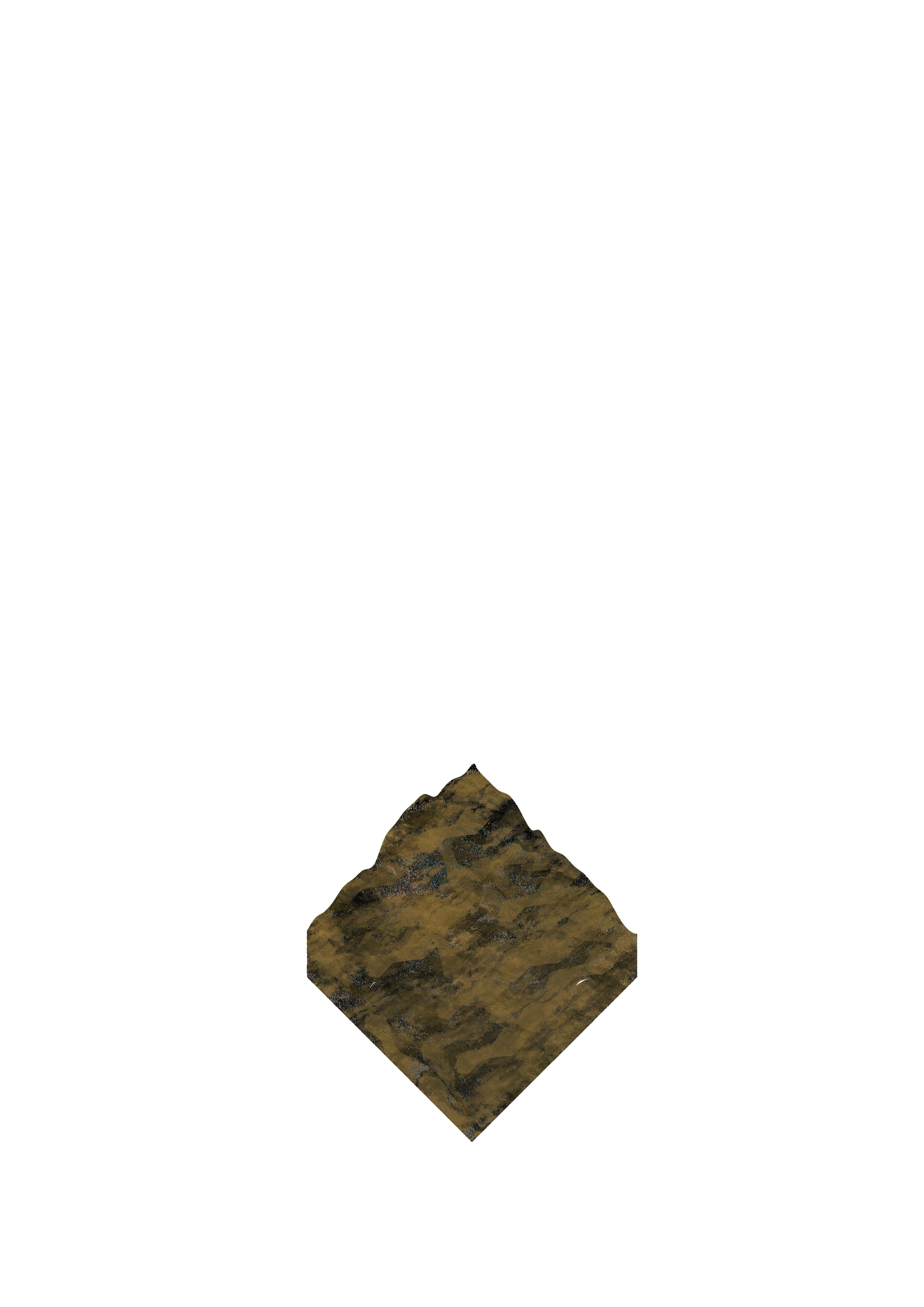
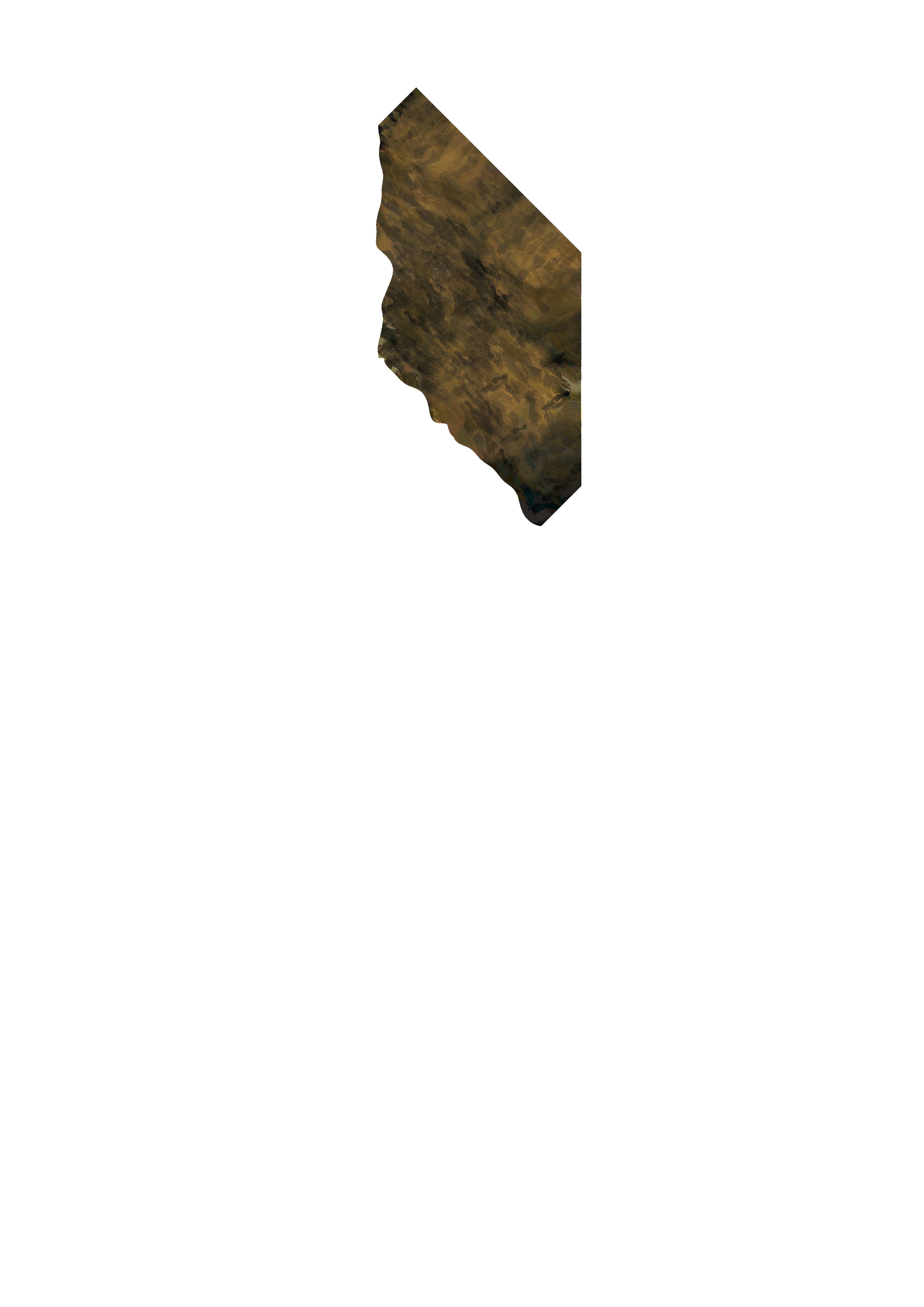
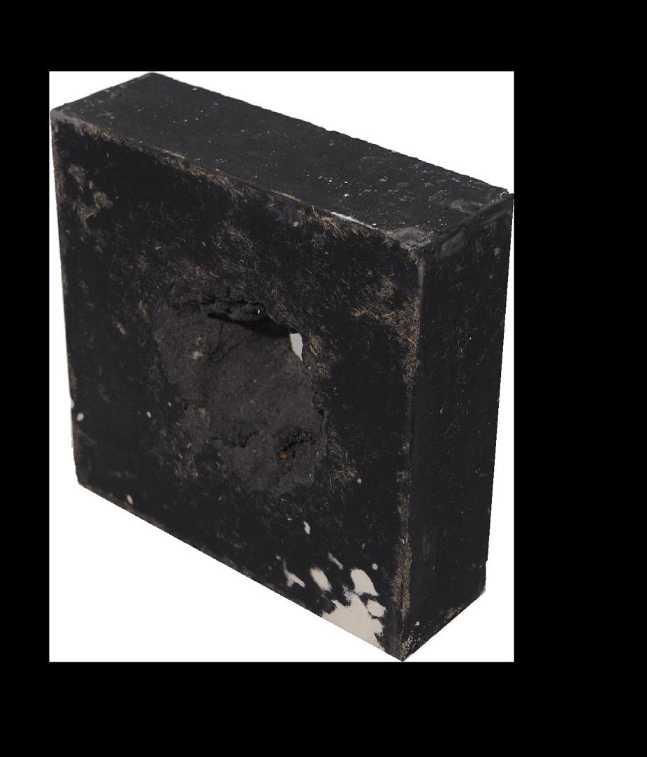
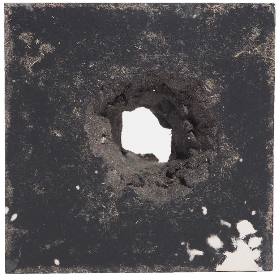
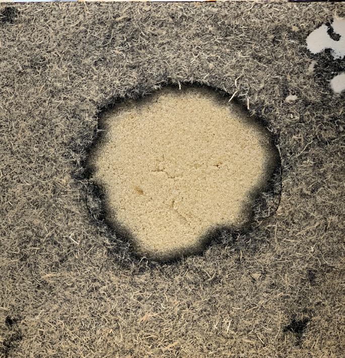
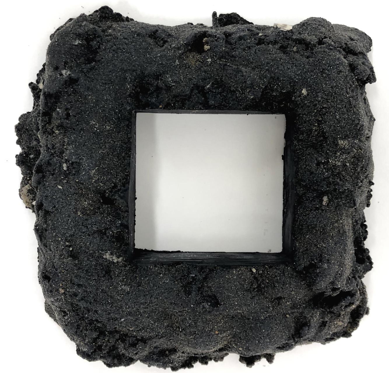
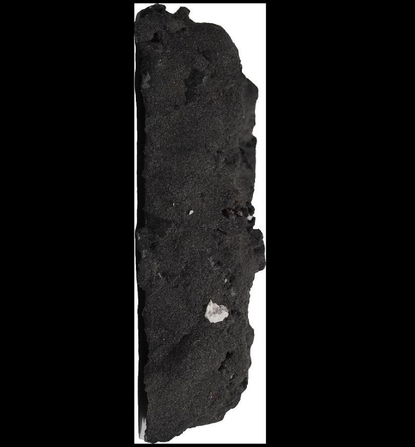
Ex2 S1 Sand Cast
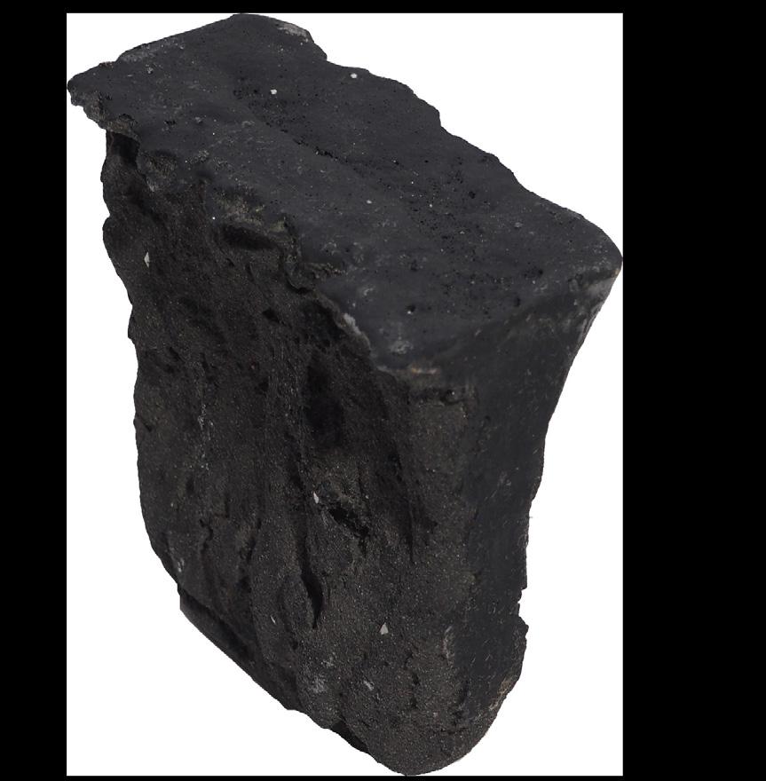
Wet sand can decrease the angle to 90 degrees if compressed
Two elements are used: - Sand formwork - Hard straight edged processed formwork
The use of theses two opposite types of formwork together allows for increased qualities in direct contrast to each other.
Number of faces exposed to sand : 2
Number of faces exposed to mdf : 3
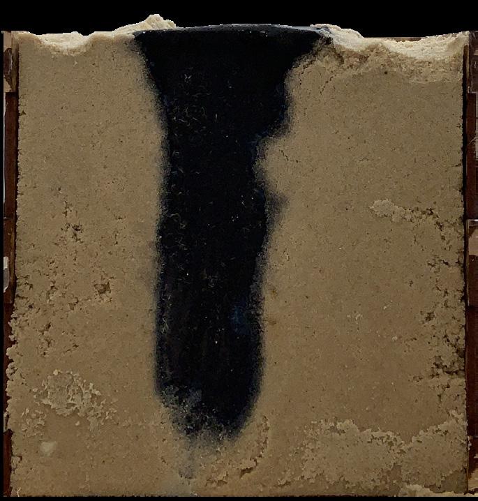
Non compressed sand leave allows for more irregular surfaces to form.
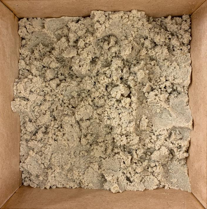

Non compressed sand leave allows for more irregular surfaces to form.
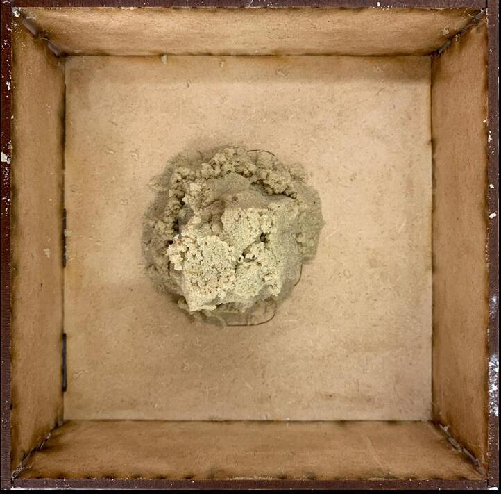


Pile and pack rest of formwork.
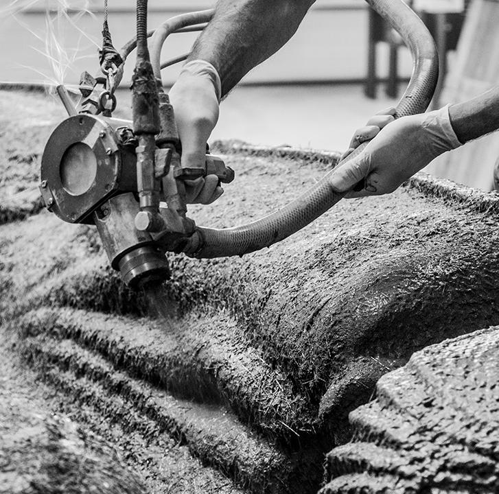
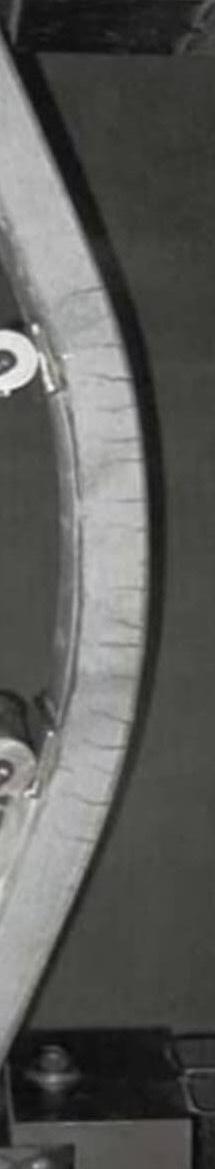
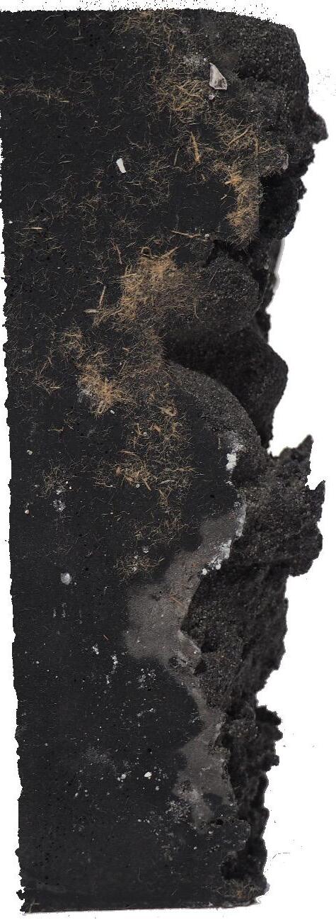
Cast base into the ground then add Industrially bundled straw.
Cast rest of formwork and cover.
Remove earth Formwork
Pile and pack sand.
Remove straw to form negative space.
Add components onto the truffle house.