11 minute read
Procurement in Construction


Mohammed Elaida MCIOB
Definition and Genesis
Advertisement
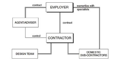
Integrated procurement system, which is also known as design-and-build, design and construct or package deal, has been in use for over 30 years. The system is known for the integration of teams of designers, constructors and suppliers working together towards the achievement of a project and continuously improving the supply chain by learning from experience, innovation and reducing waste. The system is a single financial transaction under which a chosen contractor is responsible for both design and construction of the project.
During the 1960s, literature began to show weaknesses in the traditional procurement system (addressed in last article) as construction projects were becoming more and more complex and therefore integration of the design and construction were a paramount to the construction industry. Several reports (Banwell, 1964; Latham, 1994; Egan, 1998) defined the construction industry as ineffective, fragmented and unable to satisfy its clients and customers when compared to other industries. Hence, they emphasised on integration and elimination of waste.
The design and build system (Brook, 2008)
Types of integrated procurement systems
1. Conventional design-and-build:
The Contractor assumes full responsibility of the design and implementation of the project and aims at meeting the Employer’s Requirements or Client’s Brief. The contractor is then in a position to prepare its proposals for both the design and construction of the project within the bounds of the client’s brief, ascertain the time it will take to carry out the works and prepare a cost estimate.
2. Novation design and build:
The Client appoints an architect to prepare concept design. Once the contractor is chosen, the architect is passed on to the contractor, under a novation contract, to carry out detailed design and remains the contractor’s consultant until the completion of the project.
3. Develop and construct:
The contractor inherits the design that has been prepared by the client’s consultants, to a partial stage. The contractor has to develop such design to detailed stage, and construct the works.
4. Package deal:
In addition to the design and construction of the works, this system may include the provision of site pursuing and purchase, acquiring planning permission and building regulations approval, financing facilities, leasing etc...
5. Turnkey method:
This system is, as the name implies, a method whereby

one organisation, generally a contractor, is responsible for the total project from inception, design and through to the point where the key is inserted in the door’s lock.
Appropriateness
- If there is a need to make an early start on site – can overlap design and construction

- Where clients desire to minimise their risk on and control over responsibility for design
- For technically complex projects which can benefit from the contractors’ expertise
Advantages:
- A single point of responsibility for clients with one design-and-build organisation
- Early price certainty, generally a lump-sum value
- Client and contractor have a direct line of communication
- Concurrent design and construction and earlier commencement on site lead to reduction of the project duration
- Since the design is carried out by the contractor, variations are restricted. This mitigates time and cost overrun; and disruption of the works.
Disadvantages:
- Client may have difficulty preparing a sufficiently com prehensive brief
- Harder to compare tenders and determine if they offer value for money
- Client may have to commit to an early concept design
- In conventional design-and-build system, client has no control over the design
- Variations from the original brief may be difficult to assess

Prof. Ruben Paul Borg
Coastal infrastructure assets include ports and critical structures which serve as catalysts of economic development, supporitng global supply chains. Coastal structures are directly exposed to extreme aggressive marine environments and to the risk of climate change impacts. Coastal transport infrastructure and ports have a strategic role in global trade and disruptions have significant ecomomic impacts. Coastal structures have a long service life with significat impacts and major consequences in case of failure. Therefore, securing their resilience is critical. Coastal infrastructure primarily consist of reinforced concrete structures under marine exposure conditions (XS) which experience several time-dependent durability problems, requiring early and often continuous maintenance. Typical pathologies include excessive corrosion, accompanied by cracking and spalling of concrete cover. It is reported that 50% of repaired concrete structures failed again, 25% of which in the first 5 years, 75% within 10 years and 95% within 25 years. In view of the long service life of coastal structures, the major consequences of failure and associated economic impacts, resilience building necessitates a re-thinking of establihsed practice and approaches in engineering.
The durability and long-term behaviour of structures under extremely aggressive exposure conditions can highly benefit from the use of
high-performance materials, in the
framework of durability-based design approaches.
The Engineering Materials and Structural Monitoring Research group at the University of Malta worked as a key partner in the ReSHEALience Horizon 2020 Project (GA 760824), with the main objectives being the development of [a] an Ultra High Durability Concrete (UHDC) for Extreme Aggressive Exposures (EAE) and (b) a Durability Assessment-based Design (DAD) methodology to improve structural durability and predict long-term performance under EAE. UHDC is defined as a strain-hardening (fibre reinforced) cementitious material with functionalizing micro- and nano-scale constituents especially added to obtain a tailored durability in the cracked state. The project addressed the development of UHDC with self-healing properties, by upgrading the UHPC/UHPFRC concept through the incorporation of tailored nano-scale constituents including alumina nano-fibres, bio-based nano-cellulose and crystalline admixtures. The project further focused on upgraded experimental methods to validate the durability in service conditions and development of theoretical models to evaluate ageing and degradation of UHDC structures in order to predict their lifespan.
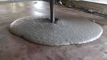
New design concepts were proposed and further validated through long-term monitoring of six full-scale proofs-ofconcept structures. The structures which were designed, constructed and monitored, were selected as representative of cutting edge economy sectors, incluidng Green Energy, Blue Growth and the conservation of Coastal reinforced concrete heritage structures. The prototype structures included a cooling tower water basin, a geothermal mud collection tank in Italy, a floating off-shore wind turbine, a floating platform installed offshore from the Spanish Mediterranean coast, a precast breakwater installed along the British coast and the restoration of a severely damaged water tower in the Grand Harbour in Malta.
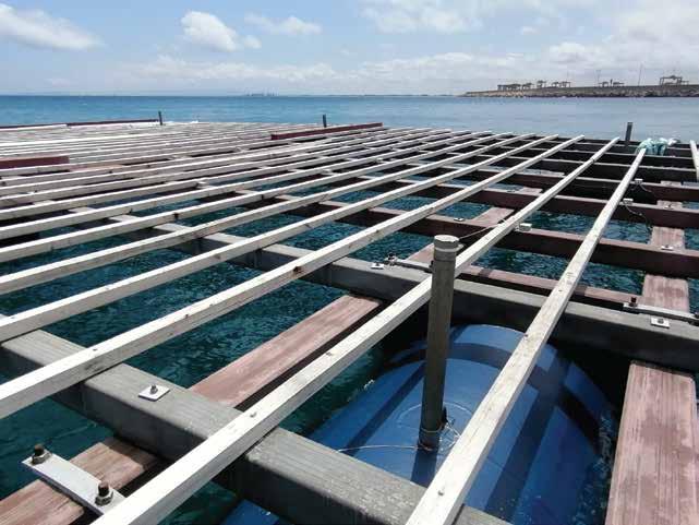
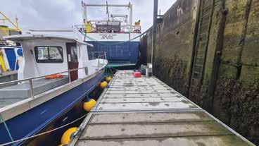
Floating Ultra High Durability Concrete Platform, RDC and Pre or
The floating structures developed in our project, push the boundaries in engineering to stimulate and induce innovation in coastal and marine infrastructure.
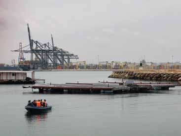
The developed offshore projects including the floating wind turbine, the floating platform and the floating breakwater, were designed and constructed using the new technologically innovative UHDC. The floating structures are monitored over time to assess their performance in EAE, using advanced sensor network systems for durability and structural health monitoring. The projects secured the achievement of a level equal to Technolgy Readiness Level 7. The ReSHEALience Project addressed the needs of structures exposed to extreme aggressive environmental conditions through an innovative material concept and a tailored durability-based holistic engineering design approach. The demonstration projects designed, constructed and monitored in extreme aggressive environments including offshore floating structures, allow for an appreciation of the true performance of materials and structures over time.
Offshore energy infrastrucure has developed rapidly to address decarbonisation goals. The ratification of the Paris Agreement pushed low-carbon targets to the top of the policy agenda, further promoting sustainable energy systems. This stimulated further offshore energy structures with a growing interest in exploiting the potential of offshore infrastructure in deeper waters in Europe, through Floating Sustainable Energy Islands.
Ultra-High Performance Concrete - UHDC prototype structures and floating islands, as effectively developed through this project, present an important technological development in achieving resilient infrastructure and in supporting the decarbonisation goals.
Prof. Ruben Paul Borg is Principal Investigator of the ReSHEALience Horizon 2020 Project (GA 760824), at the University of Malta (ruben.p.borg@um.edu.mt) https://www.um.edu.mt/ben/constructmanage/ ourprojects/thereshealiencehorizon2020project The research activity reported in this article has been performed in the framework of the ReSHEALience Project (www.uhdc.eu) coordinated by the Politecnico di Milano. The project has received funding from the European Union’s Horizon 2020 research and innovation programme under Grant Agreement No.760824. The information and views set out in this publication do not necessarily reflect the official opinion of the European Commission. Ultra High Durability Concrete for Floating Structures
Floating Ultra High Durability Concrete Platform, RDC & Pre or
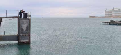
Floating Ultra High Durability Concrete Breakwater structure, Banagher Precast Concrete
Floating Ultra High Durability Concrete Wind Turbine element, Rover Maritime Group
Quality in Construction
STRUCTURAL TESTING OF EXISTING STRUCTURES - Part 2
Depth of Carbonation testing
Where concrete is exposed to air, carbonation of the cement matrix will gradually advance from the surface. This is a slow process in good quality concrete and is of little consequence unless embedded ferrous metal i.e., reinforcing steel is present in the carbonated zone.
This is not necessarily a problem with plain concrete, but it can remove the protective passive layer surrounding the ferrous reinforcing steel. The passive layer, which requires a pH of 10.5 to form, is characterised as an alkaline film of oxide around the steel that acts as a barrier to oxygen and water reaching the steel. If oxygen and moisture are available at the depassivated steel surface, corrosion of the steel may then occur, consequently disrupting the concrete due to expansive nature of the corrosion products (rust).
Terracore measure carbonation depth in the field using the phenolphthalein test method, applied to cored or extracted samples, in accordance with EN 14630[6].
Where concrete is partially carbonated and has not reached the reinforcement, coatings can be applied. These inhibit the carbonation front progression and the alkalinity of the concrete can redistribute to improve the passivity. Where the carbonation front has reached the reinforcement and conditions for corrosion exist, other repair methods such as cathodic protection, must be contemplated.
Ground Penetrating Radar (GPR) testing
Where destructive testing of concrete, such as coring, is not an option, GPR testing may be utilised to locate and ascertain the presence of steel reinforcement within a given structural element. GPR is a method that uses radar pulses to produce images of the subsurface so customers can safely carry on with their projects without any surprises. Apart from the presence of steel fabric, GPR may also detect obstructions in buried concrete such as water and power lines, voids in concrete and fibre-optic lines GPR imaging devices also detect variation in the composition of the ground material with no digging or excavation being necessary.
At Terracore, we carry out a multitude of other specialised concrete investigation testing, assisting our clients in developing a tailor-made testing program specific to their project and budgetary requirements, inclusive of reporting and recommendations for repair works, whenever this is necessary.

Quality in Construction
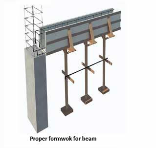
Different Elements of Construction:
In the last edition we explained about the column and stages of checking the column were discussed in detail, This month we are describing the beam, a horizontal element, which plays an important role of the structure
Factors affecting the quality management system in construction:
• Poor workmanship • Poor Design • Miscommunication between teams • Failure to document changes and practices
A case study on one of the structural elements (beam)
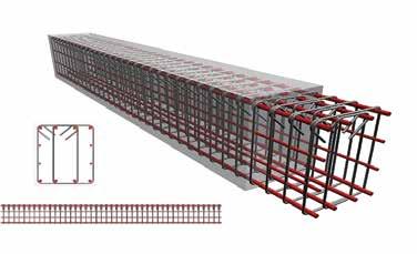
Fig A
Fig B A beam is generally a horizontal member which transfers the load of slab to column and to ground through footingtesting.
Five stages of Quality checking of the beam:
• Checking the beam layout and Centre. • Checking the beam reinforcement • Checking the beam shuttering • Checking the beam concreting • Checking the beam de-shuttering. The reinforcement of the beam should be fixed and checked first, then the shutter be fixed.
Checks for reinforcement:
• The reinforcement steel should be free from any loose scale, rust or oil. • Main bottom, top , side reinforcement and the Stirrups should be cut and bent as per the required length; this has to checked against the drawing. • Diameter, number of rebars and spacing should be checked against the drawing. • Binding wires used should not protrude in the cover zone. • Hook angles should be 135o this is very important from seismic consideration. • Lapping should be provided in the central half of the member length and lap length should be 45D or as specified. • Mill test certificate describing the physical and chemical properties of the steel.
Beam Shuttering:
• Shuttering should be properly aligned as per drawing and surveyor’s marking. • Dimensions are to be checked against drawing. • Shutter surface in contact with concrete should be clean, free from dirt, debris and other substances that may affect concreting or finished product. • The gaps b/w the joints of shutter to be sealed to prevent the leakage of slurry. • Cover should be minimum 40mm unless otherwise specified.
Beam concreting:
• Grade of concrete as per the design mix. • Height of concrete Pour. • Slump and temperature check • Ensure the Vibrator is ready and in working condition and used for at least 30 seconds in each area. • Excess water or superplasticizer was not added to concrete on site. • The concreting is carried out within specified time period (90 minutes) from the batch time. • Sampling of cubes for density & compressive strength testing.