6 minute read
Pitch and yaw control of blades and nacelles
In the age of renewable energies, wind turbines are by far the most important form of wind energy used today. In this system, the kinetic energy of the wind is converted into electrical energy and fed directly into the public power grid.
WORDS BY STEFAN KINCSES, INTERNATIONAL SALES MANAGER AT WANDFLUH. ALL IMAGES COURTESY OF WANDFLUH.
Wind turbines, also commonly called wind power plants or simply wind mills, are installed onshore or in so-called ofshore wind farms in the coastal foreland of the oceans. Wind turbines installed on land have a nominal power of up to 5MW, with the largest ofshore turbines developed to date reaching a nominal power of up to 15MW and a total height of over 200m. Essentially, a wind turbine consists of a foundation, a tower, a rotor consisting of a rotor hub with two or three rotor blades and a nacelle containing a gearbox, a generator, and a braking system. Additional monitoring and measuring devices ensure that the system functions without malfunctions and incidents.
Pitch control with hydraulic valves

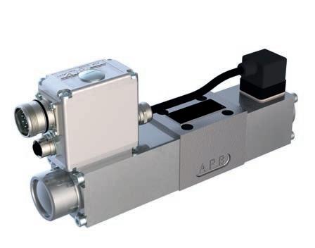
The most widespread design of the turbines today is the three-bladed wind turbine lift type, which rotates thanks to the aerodynamic uplift principle. Uplift is created by the pressure diference between the bottom and top of the aerofoil as wind fows around the rotor blade. Rotor blades are elementary and function-determining components of wind turbines. The rotor with the rotor blades turns by the force of the incoming wind. This movement is transferred to the generator by the gearbox, thus ensuring the conversion of wind power into electrical energy. It is important to keep the speed of the rotor constant in order to ensure the synchronisation of the grid frequency via the generator. Furthermore, in order to reduce mechanical load and extend the service life of the turbine, the speed of the rotor must also be kept below the maximum permissable. All these conditions are met with the help of the rotor blade adjustment, the so-called pitch control. For maximum efciency rotor blades should always be precisely aligned to extract as much usable energy from the wind as possible. To enable efcient energy conversion, the rotor blades’ pitch angles are continuously adjusted by hydraulic cylinders located directly in the rotor hub. Highly dynamic proportional spool valves, such as the models of the BRWS4D41 and WDRFA06 series, play an important role in this hydraulic actuation. Thanks to their very good dynamic properties, high resolution, and very low hysteresis, these are well suited and reliable components of the pitch system. The valves are equipped with on-board electronics and have integrated spool position control. With the spool position sensor (LVDT), the actual position of the spool is continuously monitored, recorded, and made to follow the transmitted command value. The parameterisation is carried out by means of the parameterisation and diagnosis software
Proportional spool valve WDRFA06_24.
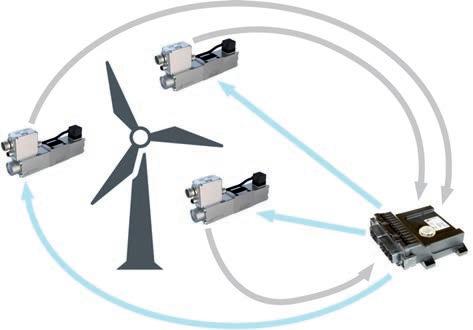
PASO. Thanks to the IP67 protection class of the on-board electronics, these valves of nominal size NG4-MINI and NG6 according to ISO 4401-03 can also be used in harsh environmental conditions. With the MD2 control electronics, a superordinated position control loop can also be implemented. In contrast to pure amplifer electronics, control electronics reads the actual value as a feedback signal, then calculates the discrepancy to the command value and gives a corresponding correction signal to the valves. Pressure, speed, and position can thus be maintained and precisely controlled independently of external infuences. The MD2 has up to eight solenoid outputs and is optionally available with CANopen feld bus. Thanks to the robust design and IP67 protection, nothing stands in the way of use in harsh conditions.

Emergency shutdown in case of strong wind
In order to counteract unfavourable or extremely stormy wind conditions, or to be able to avoid a possible selfdestruction of the wind turbine by a too fast rotation of the rotor, there is a safety function in addition to the rotor blade adjustment. The so-called emergency shutdown. With the help of fow control valves, the rotor blades are turned to ‘0’ within a very short time, out of the wind, so to speak. Due to the decreasing centrifugal force and its own inertia, the wind turbine continues to turn slowly, but comes to a standstill after a short time. Flow control valves keep the speed of a consumer constant, independent of pressure or load. A fxed measuring orifce integrated in the pressure compensator spool determines the volume fow. When the pressure changes, the pressure compensator spool shifts and changes the fow cross-section so that the pressure diference at the measuring orifce is kept constant. The desired fow rate can be adjusted by changing the spring force acting on the pressure compensator spool. Thanks to this load independence, the speed all of the rotor blades’ rotation can be controlled precisely and synchronously, regardless of the wind strength. Wandfuh has a wide range of fow control valves, proportional and mechanically adjustable. Screw-in cartridges are available with thread size M18, M22, M33, and M42 according to ISO7789 and with UNF thread. For the modular construction, the nominal sizes NG3MINI and NG4-MINI, as well as NG6 and NG10 according to ISO 4401-03 / ISO 4401-05 are available. Typically, for emergency rotor shutdown applications mechanically adjustable two-way fow control cartridges are used. Depending on the thread size, volume fows of less than half a litre up to 160l per minute can be precisely controlled.
Control circuit with MD2 electronics.
Yaw control for optimum efciency
Hydraulics also support another necessary positioning function on wind turbines, the yaw control. It assures that the nacelle is turned so that the rotor is aligned with the rotor blades in the direction of the wind, which leads to optimum efciency of the turbine. The drive required for yaw control is usually an azimuth drive, which is located between the tower and the nacelle. Actuation is by hydraulic motors whose direction of rotation is usually determined by two poppet valves, normally open and normally closed. Various versions and nominal sizes are also available for this task. The most commonly used are direct and pilot operated screw-in cartridges of the SDS and SVS series with various thread sizes from M18 to M42. The fow rate range of these poppet valves extends from 30l – 160l per minute.
Brake systems
Braking and holding the nacelle in position is done by a hydraulic braking system. The required brake pressure, acting against a spring force, is built up with the aid of a two-way pressure reducing valve. The model MSSPM22 is a typical pressure reducing cartridge for this application. The maximum pressure is 350 bar, with several nominal pressure levels available. The valve is used in accumulator loading operation. Thanks to its seat-tight design, unwanted leakage is prevented, which also helps to avoid rapid discharge of the hydraulic accumulators. Leakage compensation can thus be kept at a low level, which also contributes to the energy efciency of the entire wind turbine. Wind turbines are used in all climatic zones, which means that equipment and materials may be exposed to extreme weather conditions. An additional load is to be expected in ofshore applications. There is a corrosive environment due to the seawater and the high salt content of the air. With the standard zinc-nickel coating of the valves, Wandfuh ofers very good corrosion protection. A wide range of valves is also available in stainless steel. The stainless steel AISI 316L used for this purpose is acidresistant and guarantees a rust resistance of at least 2,000 hours salt spray test according to DIN EN ISO 9227.


