10 minute read
The operation and application of medium and big square balers: Part 8
from ProAgri Zambia 053
by ProAgri
Introduction to the big square baler
by GJ Stoltz (Reg Eng Tech)
Advertisement
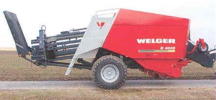
Bigger is better when it comes to commercial hay production for large herds. Bigger bales are not only more cost effective, but also less labour intensive as larger volumes can be handled at a time. When it comes to transport, the big square bale is the most economical option due to its weight to volume ratio which enables haulers to make the best use of a vehicle’s payload. The big square baler is ideal for the large-scale farmer and contractor. They have a high output with a high bale density that is essential for profitability. Some of these balers have two land wheels and the bigger ones have four. The baler trails right behind a tractor and picks up the windrow that passes
Photo 1: Baler with two land wheels. The bale chute is pointing upwards for transport purposes. Photo 2: Baler with four land wheels. The bale chute is pointing downwards for baling purposes.
through between the rear wheels of the tractor. The picked up hay then passes through the baler in a straight line and drops off at the back as big high density bales.
Operational features:
This type of baler has a high capacity and can produce bales of the following dimensions: Height: 80 cm Width: 120 cm Length: 90 to 250 cm Different models are available and their bale dimensions also differ. It is a big machine and very sophisticated. Only the basic features will be discussed in this article. For more information it is advisable to consult the appropriate operator’s manual.
Photo 3: A big bale with high density is produced. Photo 4: When turned on its side, the bale can easily be pushed through a single door.

Photo 6: The front of the baler rests on a retractable support jack. The drawbar is height adjustable. The tubes for the different hydraulic sys


tems are connected to the tractor.
Augers Central gearbox Flywheel Photo 7: The PTO drive shaft is connected to the PTO shaft of the tractor and drives the flywheel, via a slip clutch.
Packer fingers Ram Rotary packer Knotter

Component functions:
The big square baler consists of quite a number of components, but only the functions of the main components will be discussed here. These big square balers can be used for baling hay, straw and silage, and
Photo 11: The tines are mounted in u-shape channels in the pick-up.
must therefore be equipped with the appropriate components for effective baling. All functions are controlled from the tractor by means of hydraulic and electric systems.
Photo 8: The central gearbox at the top drives the other main


components of the baler.
Photo 9: A smooth flow of material into the baler is important. The crop guard keeps the material down and the packer fingers at the back move the material into the machine.


Photo 12: A castor-type support wheel on the pick-up.

Drawbar:
The drawbar, which hitches the baler to a tractor, is height adjustable and very robust. When the baler is parked, the drawbar rests on a retractable stable support jack.
Flywheel:
To keep the power flowing constantly, a heavy flywheel is fitted in front of the central gearbox. It balances out peak loads and reduces wear and tear on the tractor’s transmission. A wide-angle universal PTO drive shaft transmits the tractor’s power to the flywheel (see Photo 7).
Central gearbox:
The central gearbox transmits the power from the tractor and ensures power flow to the individual components like the pick-up, plunger, packer fingers and knotters. No shear bolts are used on some of the models, only slip clutches. Drive shafts are used instead of chains to ensure synchronisation of components that have to work in time, such as, for instance, the packer fingers and the plunger.
Pick-up and augers:
The baler can pick up silage, straw and hay whether the crop is brittle or short, and whether the windrows are small or large. Some of the models have two stub augers, mounted on the sides of the pick-up, that compress the hay to fit the width of the inlet channel, which is also called the feeder channel. The pick-up is lifted and lowered hydraulically from the tractor. The flexible spring steel tines are mounted in u-shaped channels and have a long working life. The pick-up has two castor type support wheels which allows pick-up to virtually float over the ground contours, while dampers prevent it from bounding. A crop guard is also provided to ensure a constant flow of material to the packer fingers. Another special feature on big square balers is the implementation of a rotary cutter. The crop flows over the pickup and over a special set of knives. At the top of these serrated knives is a rotor with V-shape prongs that guide

Photo 14: The packer fingers push a portion of hay against the bottom of the plunger.


Photo 15: Another portion of hay is collected and pushed against the bottom of the plunger. Photo 16: When a third portion of hay is collected, the plunger retracts, and the hay is pushed into the bale chamber.

the crop as it comes from the pick-up, pulling the crop evenly through the knives. The crop is cut and compressed at the same time. When the prongs feed the crop through the knives, they create a slicing action. The knives can be engaged or disengaged hydraulically from the drivers’ seat. If a blockage occurs, disengaging the knives often helps to clear it quickly. The number of knives can be changed according to the cutting length required.
Packer fingers (packer tines):
The packer fingers transport the hay through the feeder channel on its way to the bale chamber, and some machines also use a rotary packer for feeding the hay into the bale chamber. The packer fingers are driven by shafts. No chains are involved, which reduces maintenance considerably. The packer fingers take over after the hay has passed through the pick-up and accelerates the material upwards into the bale chamber. The packer fingers operate in two stages. During the first stage a portion of the hay is pushed up against the bottom of the plunger. During the second stage the packer fingers collect some more hay and when the plunger is retracted, the complete package of hay is pushed into the bale chamber. The bales are compressed in slices

Photo 17: Bale slices make it easier to feed animals. Photo 18: The panels of the pressure chamber are adjusted hydraulically to control the density of the bale.
and this is clearly visible when the twine is removed and a bale falls apart in segments. This makes it easy to feed the bales to animals because the separate portions make it easy to give each animal just the right amount.
Plunger (Ram):
The plunger, or ram, is driven from the central gearbox, and is connected to the gearbox by two heavy duty connecting rods. At the bottom, the plunger is equipped with a knife that ensures a clean cut after the hay has been forced into the bale chamber by the packer fingers. The knife cuts over a stationary shear bar mounted at the bottom of the bale chamber.
Bale chamber and bale chute:
The hay is compressed in the bale chamber by the strokes of the plunger, and from there it moves to the bale pressure chamber before the bale finally exits the machine down the bale chute. The panels of the bale pressure chamber can be adjusted closer or further apart to control the density of the bales. The density of the bale is displayed on a pressure gauge at the front of the baler and on some models also on a monitor screen in the tractor cab. The panels of the bale pressure chamber can be adjusted hydraulically from the tractor seat, and very strong springs are used to support the floating panels. A bale chute is mounted behind the bale pressure chamber and this chute can be raised and lowered as conditions require. On some models, the chute contains rollers that allow the bale to slide gently down onto the field.
Needles and knotters:
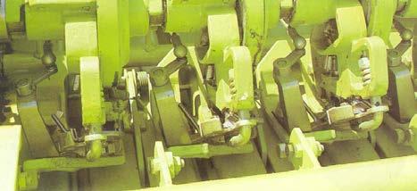
Some models use four knotters to tie twine around the bales, and others use six knotters. The knotters are driven by a shaft from the central gearbox and gears are used inside the knotter

box to maintain synchronisation. The

Photo 19: The pressure gauge on the right-hand side indicates the bale density. The flashing light on the left comes on when there is no supply of twine to the needles. The bale counter can be seen at the top.
Photo 20: The chute allows the bale to slide down onto the field. As the compressed hay moves down the bale chamber, a bale measuring wheel measures the length of the bale that can be set according to requirements. Photo 23: Part of a knotter box with electric fans at the back.


Photo 21: The bale measuring wheel on top of the bale chamber. After the baling process, the final bale or part of a bale is removed from the bale chamber by a special hydraulic bale ejector that shifts the hay out


to clear the bale chamber.


Photo 24: Spools of twine are kept in compartments on the sides of the baler. Photo 25: On this model, four needles are supported by a strong frame that pushes the needles upwards to the knotters.

twine is fed from the twine compartment to the needles and these balers normally use sisal or synthetic twine without resetting the knotters. Electric fans are used to keep the area around the knotters free of dirt, like straw debris or chaff. An indicator lamp is mounted at the front of the baler and this flashing light comes on when there is no supply of twine to the needles. Each knotter is serviced by a needle which takes the twine up to the knotter for the bale tying process. These needles must be adjusted according to the operator’s manual for that specific machine. The four, or six, needles are mounted onto a rocker arm that swings the needles upwards from beneath the bale chamber, taking the twine to the knotters as soon as the compressed bale is the desired length (see Photo 25). The knotters complete a knot in every string of twine that was wrapped around the bale during the baling process, and the needles are quickly retracted before the plunger compresses the next slice of hay in the bale chamber. After each knot is completed, the twine is cut by the knotter mechanism, and the bale density stays intact as the bale is ejected from the bale chamber and onto the ejection chute.
Next month we shall take a look at the electronic control systems of the baler, as well as general maintenance guidelines.
We thank the ARC Agricultural Engineering in South Africa who made the information on square balers available to the readers of ProAgri Zambia.


