6 minute read
REFRIGERATION Oil cooling for screw compressors – Part I
OIL COOLING FOR SCREW COMPRESSORS
During the vapour compression process, the refrigerant heats up. The amount of temperature and enthalpy increase depends on the refrigerant type, the compression efficiency, the pressure and temperature entering the compressor, along with the discharge pressure.
Refrigerants heat up in varying amounts according to their thermodynamic properties. For example, even though R404A and R507 are very similar refrigerants, the resulting discharge temperatures will be different after the compression on process.
The return gas conditions also affect the final temperature of the refrigerant leaving the compressor. So, a higher suction superheat will result in a higher discharge temperature.
The efficiency of the compressor also has an overall impact on the final discharge temperature. The higher the efficiency of the compression process, the lower the discharge temperature will be.
As the compression ratio increases, the heat of compression increases. It is very important that the discharge temperature of the compressor does not exceed the compressor manufacturer’s published limits. Ideally, it is recommended to stay well within the limit and not just hover at the limit.
With reciprocating compressors, head cooling fans and liquid injection are the two common auxiliary cooling methods used. With screw compressors, oil cooling or liquid refrigerant injection are used.
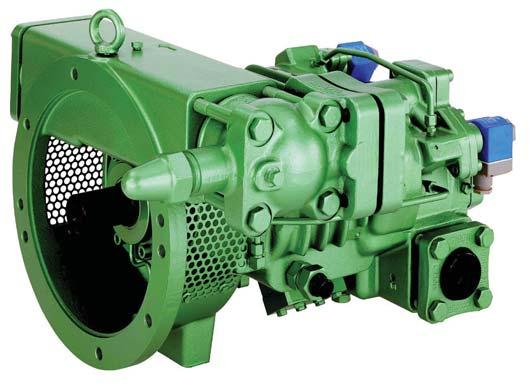
In twin-rotor screw compressor designs, the rotating helical rotors are coated with a film of oil. This oil film occupies the volume between the two rotors, as well as the volume between the rotors and the rotor housing. This oil maintains the dynamic seal required for compression. Due to the large volume of oil entering the rotor area, approximately seven to 10 GPM for the compressor used in Table 1, there is the same amount of oil leaving the rotors via the discharge port. Also, this oil will be at the same temperature as the refrigerant leaving the compressor. The oil is then separated from the refrigerant, cooled if necessary, and then returned to the compressor’s oil injection port.
The oil separator holds a generous quantity of oil to ensure there is always a good supply of oil available for compressor lubrication and also to maintain good high to low side sealing of the refrigerant compression process. With screw compressors, leakage will slowly increase with compression ratio. This also drives the discharge temperature upwards.
Unloading a compressor has the effect of decreasing the effective length of the rotors. With a shorter effective rotor length, the discharge temperature tends to climb due to the additional leakage that takes place at higher compression ratios. This is the reason why the amount of unloading is usually limited at higher compression ratios.
Phil Boudreau Phil is the Ontario sales manager for Bitzer Canada Inc. and provides training and technical support for Bitzer’s clientele. He can be contacted at: pboudreau@bitzer.ca.
REFRIGERANT COMPARISON TABLE 1 OIL COOLING LOAD AND PERCENTAGE OF COOLING CAPACITY Table 1 shows the performance of a 178 CFM, open-drive screw compressor using various refrigerants. The refrigerating capacity and oil cooling capacity varies with refrigerant type. The oil cooling loads listed, were determined using the compressor manufacturer’s software and were based on maintaining a maximum discharge temperature of 175°F. It is possible to adjust this value, as long as the manufacturer’s limitations are respected. However, this will also increase or decrease the oil cooling load requirement. The value chosen in this case, is the recommended value for efficient, long-term compressor operation.
To calculate the oil cooling load, we need to find the enthalpy of the discharge without cooling and then subtract the enthalpy of the discharge at 175°F. Next, we multiply the result by the mass flow rate leaving the compressor.
HOW TO SUPPRESS THE DISCHARGE TEMPERATURE
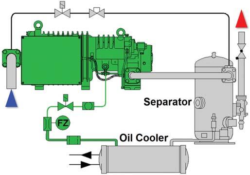
Either liquid injection or oil cooling may be used to supress Even though most screws are equipped with a discharge the discharge temperature. Liquid injection is the easiest and temperature sensor, the increasing amount of liquid most economical solution. However, the use of liquid injection injected into the rotors will tend to suppress the discharge is very limited. The reason for this is that liquid injection tends temperature. As you can imagine, this could significantly to dilute the oil, reducing its viscosity. The reduced viscosity in reduce the life of the compressor. Fortunately, most openturn, leads to less compressor drive and semi-hermetic lubrication and less of a screws are equipped with compression seal, which in turn oil flow monitoring switches. reduces compressor life. Additionally, the oil separator is monitored to ensure the oil As a general recommendation, level does not drop too low. it is a good idea to limit If the oil supply is too low, it is refrigerant injection cooling possible for the liquid injection to a maximum of 10 per cent flow rate to increase. of the compressor capacity. However, the compressor The simple oil cooling circuit manufacturer must be shown is for a water or consulted for its actual aqueous solution as the oil recommendations whenever cooling medium. There are possible. several ways to provide oil When the oil cooling load SIMPLE OIL COOLING CIRCUIT cooling, depending on the cooling medium available. Oil exceeds 10 per cent, the viscosity of the lubricant decreases. coolers can be direct expansion, water-cooled or air-cooled.Table 1 indicates the oil cooling load along with its percentage of cooling capacity for the various refrigerants for the subject When an air-cooled condenser is used, oil cooling can also compressor. be incorporated into the condenser. However, it is important to remember that the oil cooling still needs to be controlled Oil cooling is the better option and optimizes compressor separately from refrigerant condensing. life; even when the oil cooling load is less than 10 per cent. Consider what happens when there is reduced oil Mixing valves are commonly used in oil cooler circuits to flow entering the compressor. In this case, the discharge allow the oil to bypass the oil cooler on start-up, allowing temperature will tend to increase. the oil to warm up quickly.
Remember that economizing has some influence over the final discharge temperature. In economized applications, refrigerant is evaporated at a pressure several psi higher than the suction pressure. The latent heat required to accomplish this is removed from the liquid travelling to the metering device.

Again, it is important to remember that high-side mass flow rate must be used when calculating the oil cooling load. This is especially true with economized screws because the high-side mass flow rate is the sum of the mass flow rates through the evaporator and the economizing subcooler. If the low-side mass flow rate is used, the calculated oil cooling load will not be high enough to maintain the desired discharge temperature.


In the next article, we will discuss oil cooling further and explore the different oil cooler and mixing valve arrangements required to support reliable, robust compressor operation for many years.
Counterflow for Superheat and TD

COUNTERFLOW CORRECTION
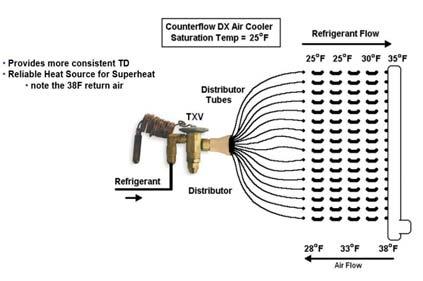
In the September/October 2020 issue, we discussed how a counterflow arrangement is generally preferred. The arrow showing the airflow temperature was placed in the wrong direction. The graphic shown here is correct. The key point of the discussion was to illustrate how this provides more consistent TD and provides a reliable heat source for superheat. Our apologies for the error and any confusion it may have caused.


