35 minute read
Session 1 Electrification for big ships


SESSION 1
Electrification for Big Ships
DR. TORSTEN BÜSSOW
Managing Director, Electrical & Power Systems Business, Wärtsilä
BIOGRAPHY
Dr. Torsten Bussow manages Wärtsilä’s electric & power systems business which includes electric drive solutions such as diesel-electric, hybrid, zero emission,shaft generator and shore connection systems. He has been bringing newtechnologies, often around digital innovations, into shipping for over 13 years as businessunit director in DNV GL and Wartsila. Before that he ran digitalisation and strategytransformation projects in a global consultancy brand.
STEFAN GORANOV
General Manager, Sustainability Solutions, WinGD
BIOGRAPHY
In his current role, Stefan is responsible for sustainability advisory and creating value-based solutions that improve the environmental and financial performance of ships operations through electrification and digitalisation. His career in the maritime industry has spanned over 20 years, where he has held various technical and managerial positions.
Today, Stefan’s team advises ship owners, operators, charterers, and financers in the field of sustainability in the maritime industry – from technical and economic assessments, to defining system features and user experience. They also develop and deliver turn-key energy efficiency solutions for new and existing ships, tailored to concrete requirements.
SIMONE BERNASCONI
Head of Global Product Line Upgrades, Accelleron
BIOGRAPHY
Simone heads Global Product Line Upgrades, a cross-functional product line focusing on supporting owners and operators in achieving higher operational efficiency with lower fuel consumption while meeting environmental regulations. Simone began his career at ABB Turbocharging in 2008 as an application engineer. He later led Engine & Turbocharging Systems in Technology, following which he joined the Service organization and held several positions before leading the Upgrades team, a position he has held since 2020.
Simone holds a master’s degree in mechanical engineering from the ETH Zurich and a Certificate of Advanced Studies in Corporate Finance from the University of Zürich.
Turbocharging solutions to support the decarbonization journey
ABSTRACT
To support shipping’s journey towards decarbonization, easy-to-implement turbocharger technology can play an important role in reducing the CO2 footprint of existing installations. But to achieve any significant impact, wide market adoption is key. Combining greater efficiency with a sound business case will be vital to maintaining a competitive edge in a low carbon world.
INTRODUCTION
Maximizing the fuel efficiency of merchant vessels has always been a key goal of the shipping industry. Fuel costs are the major operating expense in marine transport [1] and have risen meanwhile to dramatic high values.
However, there is a new aspect that has joined the game: the decarbonization mega-trend is gaining momentum at fast pace and further enhances the need for improving transport efficiency.
Ambition loop and disruption of transport sector
The development of the long-term decarbonization ambition of virtually all players in the maritime industry has been showing unprecedented expansion in the last 5 years. One of the first game changers was formulated by the IMO in 2018, targeting a reduction of CO2 per transport work of 40% by 2030 when compared to levels in 2008, and an absolute reduction of 50% by 2050 irrespective of the (increased) globally transported volume [2].
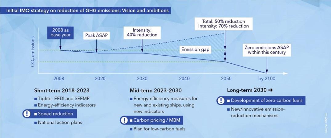
Figure 1: IMO decarbonization goals [3]
Back in 2018 those targets were perceived by many with skepticism: being too strict, costly and not realistic. Many players in the maritime industry were questioning why shipping should decarbonize at all.
Looking at the market nowadays, only 4 years later, we now observe a completely different picture. An ongoing, continuous ambition loop towards considerably stricter targets supported by key players across the industry. Meanwhile, decarbonization is not only accepted, but also expected.
An increasing number of customers in marine transport (e.g. Nike [4] and IKEA [5]) are openly declaring commitment to improving their environmental impact and decarbonizing their supply chain. Financial institutions like bank and insurance companies are defining frameworks as e.g the Poseidon Principles for banks and insurances [6] to enforce the compliance of their financed / insured portfolio of ships with the 2050 IMO global GHG emission target. Local and regional regulation as well as taxonomy are being defined and we can expect them to enter into force in the next decade, e.g. the fuel GHG standard FuelEU Maritime [7] and the inclusion of shipping in the EU ETS [8]. Global efficiency standards will be tightened and enhanced in the coming years [9], e.g., IMO’s EEXI [10] and CII[11]. These regulatory developments will further accelerate the decarbonization of the maritime industry.
Overall, the commercial, political, and social pressure on the maritime industry to reduce the environmental impact is high and we expect it to grow exponentially. The disruptive innovation of the energy and transport sector has started.
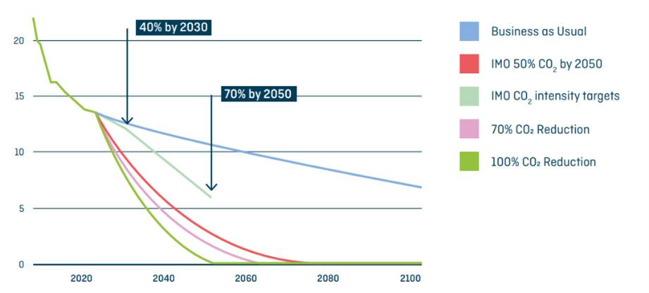
Figure 2: Carbon intensity target and trajectories for the global fleet [gCO2/tnm] [6]
In spite of showing the lowest specific CO2 emission per weight of transported goods [12] and distance as well as of having achieved solid specific emission reductions in the last decades, the maritime industry doesn’t have the image of being clean. The global perception is rather negative, often seeing maritime transportation as dirty and from time to time even non-compliant.
The expectation on our industry is high, and we - as the maritime industry - are expected to make the difference in the future. Key to success are two main aspects that must be considered and can’t be ignored when it comes to decarbonization: a holistic approach and wide adoption.
1) Holistic approach
Decarbonization needs to be implemented throughout the whole value chain, considering the overall CO2 emissions and environmental impact. Drawing the system boundary on the vessel and focusing only on downstream emissions stemming from its chimney (tank-to-wake) is not sufficient [13]. The origin of the fuel and the grey energy involved (well-to-wake) need to be considered to avoid distortion and in the worst case, global increase of CO2 emission despite of clean shipping on paper. Such life-cycle considerations, although being highly complex, are paramount to a sound decarbonization journey.
2) Wide adoption
Unlike the local character of NOx emissions, CO2 and its effect on climate plays a global role. The decarbonization targets are ambitious and consequently, to achieve a perceptible global impact, solutions for decarbonization and efficiency improvements must be widely adopted. Flagship projects are required for showcasing new technology, but their direct global impact is marginal. It is pivotal to success that technology demonstrations become widely adopted
standards within a reasonable timeframe. This may be achieved by considering global availability as well as affordability from the very early conception phase of the proposed technology.
Long term solutions (net zero transportation)
As a matter of fact, net zero maritime transportation is already possible nowadays. Fully electrified short range ferries and even medium range ferries may be possible, provided the electricity has a net zero carbon footprint. For short range ferries first installations have been already in operation for a few years [14]. For long range transportation the fully electrical approach by means of batteries is technically not applicable. A containership sailing from Asia to Europe with a 1-month travel time, would need as many as 100’000 tons of batteries on board, 60% of the freight capacity [15]. This approach is financially and environmentally not sustainable. A Net zero carbon footprint can be actually achieved by the use of sustainable fuel like biofuels or fuels generated from renewable energy sources (e.g. solar, wind, hydro, ...). From a vessel and engine technological perspective a full transition to net zero emission vessels is actually possible in less than 10 years. The major engine OEM announced availability of Ammonia engines from 2025, pilot initiatives with sustainable fuel are multiplying (e.g. Maersk [16], AIDA [17]).
Yet the global transition will take several decades to be implemented. The reasons behind this huge difference can be named directly: fuel. The biggest challenge to overcome is the global availability and distribution of net zero carbon fuels (e.g. even for a globally well available fuel as LNG, the distribution and local availability is still a challenge for many ports). This is going to be a long process that take decades to implement and is not directly in the hands of the shipping industry itself. There will be fierce competition for sustainable energy between industries at local and global level, onshore and offshore (electricity, heating, private transportation, aviation, construction, ...). The only technical alternative to chemical energy carriers for long haul maritime transportation would be nuclear energy. However, this technology nowadays faces low acceptance.
Transition phase - short and medium term
Presently, we are at the beginning of the carbon transition journey. Whereas the target and ambition are known, the exact means of implementation are widely unknown, and there will be many paths towards the common target.
Existing fleet
For a large portion of the existing fleet investment / divestment decisions are required. Investment strives to improve the carbon footprint of the vessel to keep its competitiveness in the market and avoid divestment.
It is certain that during the decades of carbon transition a vast diversity of technologies will emerge which cater to incremental CO2 footprint improvements. There won’t be a one fits all solution and most likely a single solution will not do the job. A sound combination of multiple incremental improvements are the key to making the existing fleet fit for the decarbonization journey. The IC engine is at the heart of emissions related to the maritime industry. During the conversion from chemical to mechanical energy, CO2 is released during the oxidation of hydrocarbon fuels. Future fuels, such as methanol, ammonia or hydrogen, once available, will enable a global netzero CO2 balance. Yet it is paramount to operate the engine as efficiently as possible: (1) in the
case of traditional fuels to reduce the amount of released CO2 and (2) in the case of future carbon neutral fuels to improve the financial sustainability (renewable fuel prices are expected to be higher compared to today’s costs of Diesel & LNG). The following section will shed light on one of the low-hanging fruit technologies already available today to decrease the CO2 emission of IC engines: turbocharger upgrades. The turbocharging system is a key component of the marine engine. Through its direct interaction with the engine, an upgraded turbocharger with higher efficiency has a leverage on emissions: (1) directly lowering specific fuel consumption and hence CO2 emissions by improved overall system efficiency and (2) enabling new engine tuning and concepts for even higher reduction potential.
So how do we integrate the latest available turbocharging technology within existing installations while maintaining a wide global adoption through a positive business case?
MARINE EQUIPMENT & TURBOCHARGER UPGRADE STRATEGIES
Maritime assets have a lifetime spanning over several decades, from 15 to 30 and more years depending on the vessel type. During this long time span the marine equipment is required to be serviced to ensure acceptable reliability, operational safety, and energy efficiency.
There are two main service approaches described below when it comes to servicing marine equipment. In this paper a third one combining the benefits from both approaches is presented.
1) The standard approach: classical service
When components need to be repaired or replaced, the conventional service approach is to install new equipment (like-for-like) having the same design & technology that was available when the vessel was delivered (old technology). This approach has certainly the advantage of being straight forward to implement, no adaptation to interfaces and automation is required and the service event can often be implemented during already scheduled port stay (in the best case, no impact on vessel schedule). The downside of this approach is that owner and operator do not profit from the technological developments achieved by our industry over the last decades. The maintenance budget is spent buying old technology, striving to achieve the original performance of the vessel during its maiden voyage.
This traditional service concept is no longer sufficient. In view of the increasingly stringent decarbonization targets, regulatory developments, as well as high fuel prices, our industry needs to rethink the approach when it comes to marine service. Every investment in servicing or replacing marine equipment is also an opportunity to apply an upgrade instead and increase the competitiveness of the vessel.
2) The upgrade approach: exchange to newer equipment design
An alternative approach to the classical service is to apply an upgrade instead. Older equipment is removed from the vessel and replaced by newer components with a more recent design. The approach has the advantage of letting owners and operators profit from the latest technology developments in efficiency, ease of service and spare part availability. Unfortunately, changing equipment to a newer version requires in many cases adaptations of the interfaces as well as to the automation of the vessel. This increases the technical complexity, project management effort and downtime required to complete the installation.
In many cases the increased complexity, direct and opportunity costs of the upgrade have a negative impact on the business case, resulting in reduced adoption of the upgrade technology in the market.
To achieve wide adoption of upgrades globally, the financial sustainability needs to be further improved.
3) The new way: component upgrade (combine simplicity with benefits)
It becomes obvious that to open the door for a wide adoption of upgrades in the market it is required to combine the benefits of the previously described approaches: 1) The simplicity of the standard service. No adaptation of interfaces, implementation during an already scheduled port stay, technical complexity the same as for a standard service. 2) Implement the latest technology in terms of design and material achieving higher efficiency, same or higher reliability, same or higher spare part availability, reduced maintenance costs.
But how can this be achieved? How can we apply upgrades while keeping the complexity at a similar level to a standard service event?
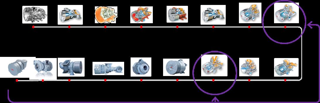
Figure 3: Integration of latest technology into older turbocharger generation
The turbocharger component upgrade is the solution to this dilemma, and is based on a simple concept: 5 The latest know-how in design and materials for the newest turbocharger generation is modified to fit into older turbocharger equipment from a previous generation. 5 Only the turbocharger internal performance relevant components are replaced by new upgrades, while the turbocharger casings and all interfaces to the engine remain untouched.
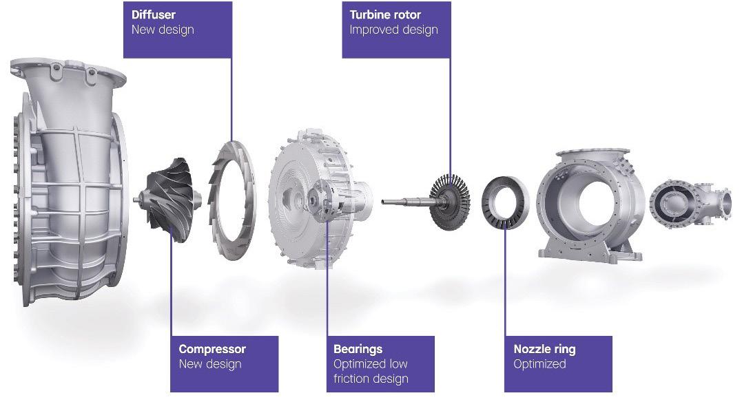
Figure 4: Turbocharger component upgrade, upgrade only the core turbo performance components
The component upgrade approach requires a dedicated development, qualification and verification effort by equipment OEM’s. Once available it provides a great alternative to the standard service for owner and operators. A great instrument to simultaneously improve the CO2 footprint and competitiveness of their vessels, without interfering with the already scheduled maintenance scheme.
PRACTICAL EXAMPLES
In line with the market requirements and targeting a wider industry adoption, Accelleron has developed several products that can support owners and operators to reduce CO2 emissions, fuel expenses and support the compliance with new regulations for the existing fleet.
4-stroke engines with TPL-A and TPL-C turbocharger
A wide portfolio of component upgrades covering the entire TPL-A and TPL-C turbocharger range has been developed. The product requirements have been strictly based on four main pillars: 1) The turbocharger upgrade shall enable a positive business case for the end customer to ensure wide adoptions globally; 2) The turbocharger efficiency shall be substantially increased to reduce the engine fuel consumption and engine thermal load; 3) The time required for implementation and technical complexity shall be similar to a standard turbo service event; 4) The recommended exchange interval of the turbocharger rotating component shall be extended by 50%. The environmental benefits can be separated into two categories: 1) direct CO2 reduction by reduced engine fuel consumption; 2) indirect CO2 reduction by reducing the number of spare parts required (grey energy for production and transport) enabled by an increased recommended exchange interval of the rotor and reduced thermal wear & tear of the engine hot components exposed to the exhaust gases.
One more thing, how to multiply the benefits?
The component upgrades have been developed in close cooperation with engine OEM’s and for many engine platforms the increased turbo efficiency is unlocking new upgrades on the engine side. The combination of engine with turbo upgrade are generating great synergies that enable fuel consumption reductions to be multiplied up to a factor of four (4x more benefits).
2-stroke engines with TPL-B and A100/200-L turbos
Many 2-stroke engines feature a fuel optimization in the power range above 75%-85% load but are operated for most of the time at lower engine power. Furthermore, in many cases EPL (Engine Power Limitation) must be applied to fulfill the EXXI limits, further reducing the service power. For those vessels there is a mismatch between the relevant engine operating range, and the actual optimal operating range of the engine. This mismatch leads to inefficiencies in terms of increased CO2 emission, increased fuel expenses and increased maintenance efforts due to higher thermal load and carbon deposits.
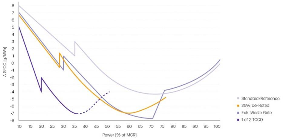
Figure 5. EPLO fuel reduction characteristics
Engine Part Load Optimization (EPLO) is a solution based on a turbocharger component upgrade to reduce the fuel consumption and improve the engine operation at part load (engine power <70%) for 2-stroke engines. The basic concept is as simple as it is effective. The turbocharger specification is optimized for a specific engine power range provided by the customer (below 75% power). To maximize the benefits, the engine tuning, and optionally also key engine components, are optimized to leverage synergies in the engine-turbo interaction. This opens the question of engine operation at higher loads after the EPLO implementation. Two different options are possible: 1) Keep 100% MCR capability by installing an exhaust gas wastegate. The resulting fuel consumption at high load will be slightly higher compared to the reference case, but is irrelevant for the overall yearly vessel performance. 2) Apply permanent engine derating, where the maximal engine power is permanently reduced. No wastegate is required. Both of the set-ups above combine well with EPL (Engine Power Limitation) to fulfill the EEXI requirement.
4-stroke engines with older generation turbochargers
For older generation turbochargers (like the VTR generation) the best upgrade option is to switch to a newer turbo version, by replacing the complete turbocharger, see Figure 6. As described above it needs to be considered that due to the change of the turbo footprint the interfaces between turbo and engine need to be adapted. The benefits in terms of efficiency gain and reduction in turbo maintenance costs overcome the drawbacks from increased complexity of the project.
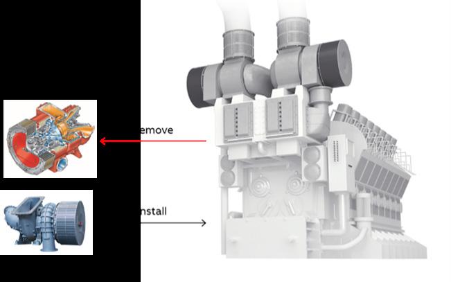
Figure 6: Upgrade by replacing the turbocharger with a new generation version
CONCLUSION
The maritime industry is going through a disruptive decarbonization journey. Even though the transition to net zero emission vessels on a global scale could be completed in less than 10 years (technology development), this process is in reality going to require several decades to complete. Whereas electrification may play a role for short range vessels, chemical fuel carriers will continue to play a key role in long range transportation. The major challenge we are facing is the global availability and local distribution capability of carbon neutral fuel.
In the transition phase it is pivotal to combine measures to progressively improve the energy efficiency of shipping and relentlessly reduce the carbon footprint. To make a significant difference in a global context efficiency measures need broad adoption. This is only possible if the technology is reliable, and the implementation is financially sustainable (positive business cases are enabled).
Internal combustion engines are at the core of emission generation for the shipping industry. Measures to reduce their environmental impact can’t be removed from the global sustainability equation and must be carefully evaluated.
The turbocharger component upgrade is a simple measure that can be integrated into the regular maintenance scheme of the turbocharger. It reduces the direct CO2 emission onboard the vessel through lower fuel consumption, and also the indirect CO2 emission (grey energy for production) by increasing the lifetime of key components (50% extended replacement intervals of rotor, reduced wear & tear of hot parts).
The key to enabling wider adoption globally relies on two main pillars: 5 Integration of the upgrades into the regular turbocharger maintenance plan, without additional engine downtime. This minimizes direct and opportunity costs of the upgrades. 5 Replace only the core performance components of the turbocharger whenever possible while keeping all interfaces untouched. This reduces the complexity of the upgrade to the level of a standard service.
Outlook
A further step towards CO2 reduction would be to leverage data to further optimize the turbo performance and maintenance pattern. This increases the productivity of the equipment, while reducing emissions directly by lowering engine fuel consumption and indirectly by optimizing the required maintenance reducing the grey energy required for its production, transport and installation.
Data may play a key role in optimizing and giving enhanced flexibility to conventional maintenance schemes by considering individual equipment status and existing customer maintenance schedules.
The recently launched Turbo SmartCare product by Accelleron [18] is a good example of data enabled service targeting highest performance, reliability, and optimization of turbocharger maintenance based on data and health assessment.
REFERENCES
[1] https://www.morethanshipping.com/fuel-costs-ocean-shipping/ (accessed on
September 26th, 2022) [2] RESOLUTION MEPC.304(72). https://unfccc.int/sites/default/files/resource/250_
IMO%20submission_Talanoa%20Dialogue_April%202018.pdf (accessed on
September 26th, 2022) [3] DNV. Achieving the IMO decarbonization goals. https://www.dnv.com/expert-story/ maritime-impact/How-newbuilds-can-comply-with-IMOs-2030-CO2-reduction-targets. html (accessed on September 26th, 2022) [4] https://about.nike.com/en/impact (accessed on September 26th, 2022) [5] https://about.ikea.com/en/sustainability/value-chain-climate-footprint (accessed on
September 26th, 2022) [6] Poseidon Principles. Assessment of climate alignment. https://www.poseidonprinciples. org/finance/wp-content/uploads/2019/07/Poseidon_Principles_Assessment.pdf (accessed on September 26th, 2022) [7] Regulation of the European Parliament and of the council on the use of renewable and low-carbon fuels in maritime transport and amending Directive 2009/16/EC https://ec.europa.eu/info/sites/default/files/fueleu_maritime_-_green_european_ maritime_space.pdf (accessed on September 26th, 2022) [8] Directive (EU) 2018/410 of the European Parliament and of the Council of 14 March 2018 amending Directive 2003/87/EC to enhance cost-effective emission reductions and low-carbon investments, and Decision (EU) 2015/1814. EUR-Lex - 32018L0410 - EN - EUR-Lex (europa.eu) [9] https://www.imo.org/en/MediaCentre/PressBriefings/pages/MEPC76.aspx (accessed on September 26th, 2022) [10] Resolution MEPC334(76). 2021 Guidelines on survey and certification of the attained
Energy Efficiency Existing Ship Index https://wwwcdn.imo.org/localresources/en/
OurWork/Environment/Documents/Air%20pollution/MEPC.334(76).pdf (accessed on
September 26th, 2022) [11] Resolution MEPC.339(76). 2021 guidelines on the operational carbon intensity rating of ships (CII rating guidelines, G4) https://wwwcdn.imo.org/localresources/en/OurWork/
Environment/Documents/Air%20pollution/MEPC.339(76).pdf (accessed on September 26th, 2022) [12] Environmental Performance: Comparison of CO2 Emissions by Different Modes of
Transport. https://www.ics-shipping.org/shipping-fact/environmental-performanceenvironmental-performance/ (accessed on September 26th, 2022) [13] IMO, Cutting ships’ GHG emissions - working towards revised strategy. https://www.imo. org/en/MediaCentre/PressBriefings/pages/MEPC-78-.aspx (accessed on September 26th, 2022) [14] Electric Ship Moves Closer to reality, Motorship Mai 6th, 2015 [15] NZZ Magazin, Die Giganten der Weltmeere müssen sauber werden, July 2nd, 2022 [16] https://www.maersk.com/news/articles/2021/08/24/maersk-accelerates-fleetdecarbonisation (accessed on September 26th, 2022) [17] Press release, AIDA Cruises starts the use of biofuels, July 22, 2022 [18] Robban Assafina, Volume 14, Issue 81 – Sept/Oct 2022, page 83. http://magazine. assafinaonline.com/books/jnhf/#p=1 (accessed on October 3th, 2022)

NATALIA ZUBENKO
BIOGRAPHY
Natalia joined the GTT engineering team in France in 2011 as a lead process engineer. Five years later, she was promoted to Business Development Manager with a key focus on EU area. Previously she held positions in DNV as an approval engineer and also in Moss Maritime, as a process engineer. Natalia graduated in 2007 from Gubkin Russian State University of Oil and Gas in Moscow with a master degree in gas processing engineering.
Improving energy efficiency including electrical production Motorship conference • November • 2022 for LNG fueled vessels Improving energy efficiency including electrical production for LNG fueled vessels. By Natalia Zubenko, Business Development Manager, GTT
Introduction
Introduction
The LNG as fuel revolution has taken off. To succeed in this transition, ship-owners need to modernize and adapt their fleets to comply with the new international regulations and The LNG as fuel revolution has taken off. To succeed in this transition, ship-owners need to environmental standards. How can we improve the fuel gas system in order to optimise the modernize and adapt their fleets to comply with the new international regulations and efficiency of a LNG fuelled vessel, in particular the electricity production on-board? environmental standards. How can we improve the fuel gas system in order to optimise the efficiency of a LNG fuelled vessel, in particular the electricity production on-board?
LNG fuel system functions
LNG fuel system functions
First, let’s recall few key functions of LNG as fuel system: primary purpose to is fed engines to produce power to propel the vessel, then electrical power needs to be generated for hotel First, let’s recall few key functions of LNG as fuel system: primary purpose to is fed engines to load. Boil-off has to be managed using consumers or, in exceptional cases, by the boiler or the produce power to propel the vessel, then electrical power needs to be generated for hotel load. vent mast. Boil-off has to be managed using consumers or, in exceptional cases, by the boiler or the vent mast. Figure1: LNG fuel system functions More and more main engines (ME) are equipped with the Shaft Generator, also called Power Take Out (PTO). Shaft generator is driven by the main engine (slow or medium speed) and supply power to the main switchboard (instead of auxiliaries). This mode is called PTO or SG mode. The opposite is also possible and called Power Take In (PTI). PTI provides propulsion power to the shaft that boosts the ME with extra power. It can also be used as an emergency backup machinery to propel the ship to the nearest shore. PTO can improve ship Energy Efficiency Design Index (EEDI), while PTI can deteriorate the EEDI figures if used for increasing the ship’s speed.
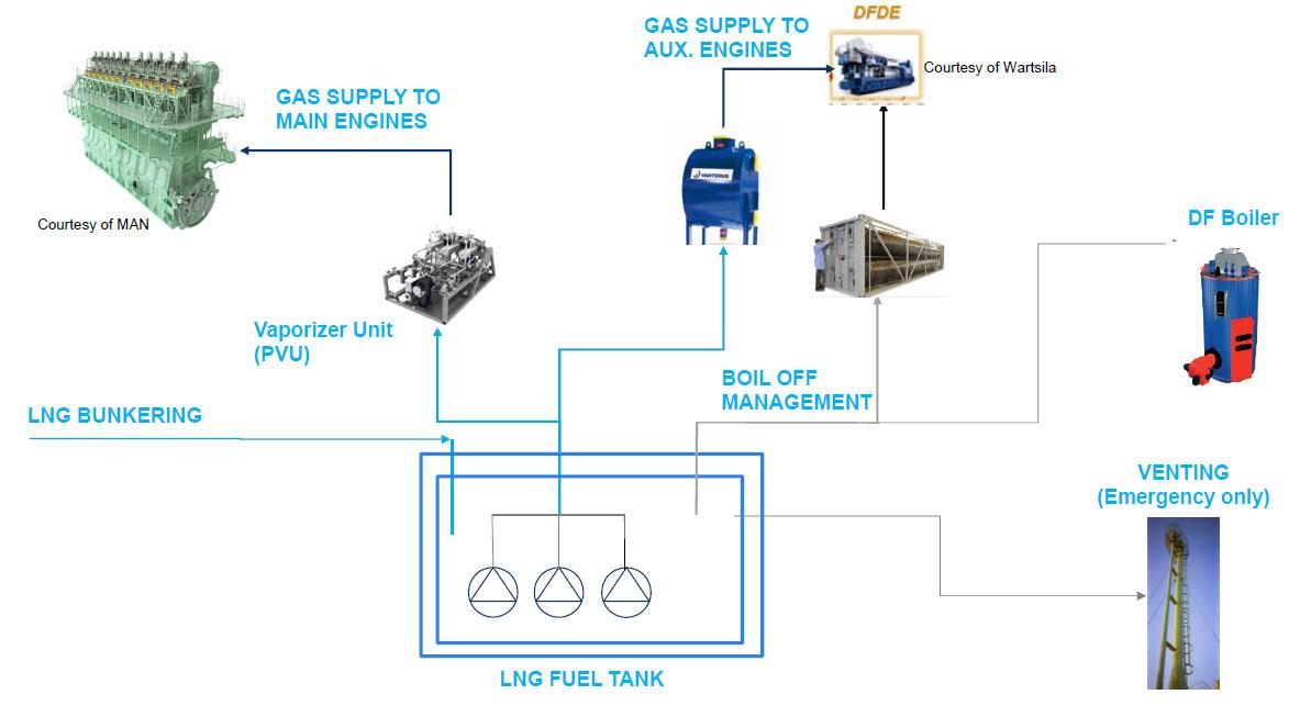
Figure1: LNG fuel system functions
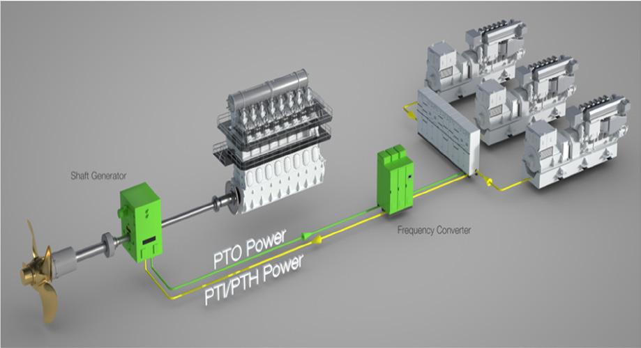
More and more main engines (ME) are equipped with the Shaft Generator, also called Power Take Out (PTO). Shaft generator is driven by the main engine (slow or medium speed) and supply power to the main switchboard (instead of auxiliaries). This mode is called PTO or SG mode. The opposite is also possible and called Power Take In (PTI). PTI provides propulsion power to the shaft that boosts the ME with extra power. It can also be used as an emergency backup machinery to propel the ship to the nearest shore. PTO can improve ship Energy Efficiency Design Index (EEDI), while PTI can deteriorate the EEDI figures if used for increasing the ship’s speed.
Figure 2: Propulsion layout
Figure 2: Propulsion layout Figure 2: Propulsion layout
Fuel Gas Handling System for MEGI engine Fuel Gas Handling System for MEGI engine Fuel Gas Handling System for MEGI engine
Here below is the basic FGHS for a vessel equipped with a MEGI engine. Here below is the basic FGHS for a vessel equipped with a MEGI engine. Here below is the basic FGHS for a vessel equipped with a MEGI engine. Figure 3: FGHS for a vessel equipped with a MEGI engine Figure 3: FGHS for a vessel equipped with a MEGI engine BOG is sent to gen-sets and boilers through the low pressure compressors. LNG is sent to the ME through PVU at approximately 300 bar and +45°C. It can be difficult to handle the BOG BOG is sent to gen-sets and boilers through the low pressure compressors. LNG is sent to the when you have low gen-set consumption. The very first solution is to select high performance ME through PVU at approximately 300 bar and +45°C. It can be difficult to handle the BOG insulation with very low BOR, as offer by GTT Mark III Flex membrane tanks. Then, one option when you have low gen-set consumption. The very first solution is to select high performance is to add an HP compressor, but this comes with high CAPEX and OPEX. The simpler option insulation with very low BOR, as offer by GTT Mark III Flex membrane tanks. Then, one option is the recondenser, with low CAPEX and almost no OPEX. The principle of the re-condenser is to add an HP compressor, but this comes with high CAPEX and OPEX. The simpler option is to use the cold power from the LNG to recondense the BOG. is the recondenser, with low CAPEX and almost no OPEX. The principle of the re-condenser is to use the cold power from the LNG to recondense the BOG.
Figure 3: FGHS for a vessel equipped with a MEGI engine BOG is sent to gen-sets and boilers through the low pressure compressors. LNG is sent to the ME through PVU at approximately 300 bar and +45°C. It can be difficult to handle the BOG when you have low gen-set consumption. The very first solution is to select high performance insulation with very low BOR, as offer by GTT Mark III Flex membrane tanks. Then, one option is to add an HP compressor, but this comes with high CAPEX and OPEX. The simpler option is the recondenser, with low CAPEX and almost no OPEX. The principle of the re-condenser is to use the cold power from the LNG to recondense the BOG.

This document is strictly confidential. Any unauthorised access to, appropriation of, copying, modification, use or disclosure thereof, in whole or in part, by any means, for any purpose, infringes GTT’s rights. This document is part of GTT’s proprietary know-how and may contain trade secrets protected worldwide by TRIPS and EU Directives against their unlawful acquisition, use and disclosure. It is also protected by Copyright law. The production, offering or placing on the market of, the importation, export or storage of goods or services using GTT’s trade secrets or know-how is subject to GTT’s prior written consent. Any violation of these obligations may give rise to civil or criminal liability. © GTT, 2010-2022 This document is strictly confidential. Any unauthorised access to, appropriation of, copying, modification, use or disclosure thereof, in whole or in part, by any means, for any purpose, infringes GTT’s rights. This document is part of GTT’s proprietary know-how and may contain trade secrets protected worldwide by TRIPS and EU Directives against their unlawful 38 acquisition, use and disclosure. It is also protected by Copyright law. The production, offering or placing on the market of, the importation, export or storage of goods or services using GTT’s trade secrets or know-how is subject to GTT’s prior written consent. Any violation of these obligations may give rise to civil or criminal liability. © GTT, 2010-2022
On engines side, 2-stroke technology have emerged as widely adopted as propulsion of choice, mainly due to better efficiency and reduced methane slip. However, feeding those engines Recondensor solution is pushing LNG as fuel efficiency to a higher level have raised 2 main questions, especially when they are of high pressure type: On engines side, 2-stroke technology have emerged as widely adopted as propulsion of 5 How to simplify boil-off gas management system – in particular with alternatives choice, mainly due to better efficiency and reduced methane slip. However, feeding those to High pressure compressors? engines have raised 2 main questions, especially when they are of high pressure type: 5 How can the wasted cold power during LNG vaporization process towards engines be recovered? - How to simplify boil-off gas management system – in particular with alternatives to High pressure compressors?
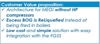
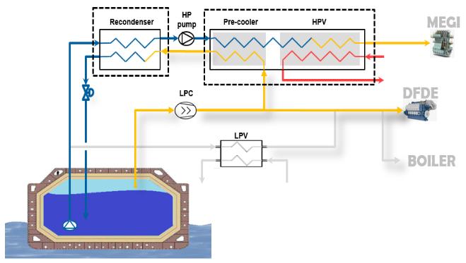
With this in mind, GTT proposes a solution that manages to solve these 2 questions at once: a compact and easy to operate recovery system – called RECYCOOL that is: - How can the wasted cold power during LNG vaporization process towards engines be recovered? With this in mind, GTT proposes a solution that manages to solve these 2 questions at once: a compact and easy to operate recovery system – called RECYCOOL that is: ‐ Compact passive system, easily integrated to recover cold on way to main engines ‐ Highly efficient & improves operability of existing supply system ‐ CAPEX competitive ‐ Reduces burden on auxilairy engines ‐ Reduces vessel carbon footprint ‐ Significant fuel savings in particular when combined with Shaft Generator (PTO) Figure 4: Simplified diagram of RECYCOOL
5 Compact passive system, easily integrated to recover cold on way to main engine 5 Highly efficient & improves operability of existing supply system 5 CAPEX competitive 5 Reduces burden on auxilairy engines 5 Reduces vessel carbon footprint 5 Significant fuel savings in particular when combined with Shaft Generator (PTO)
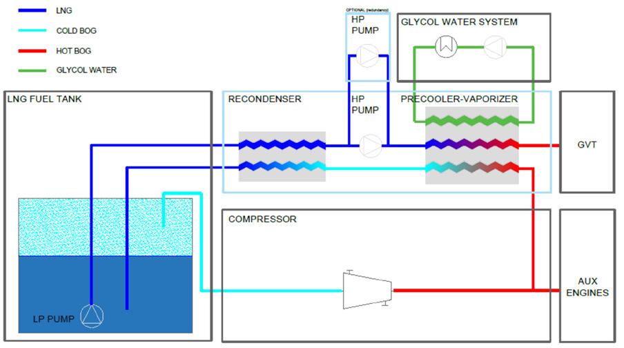
Figure 4: Simplified diagram of RECYCOOL

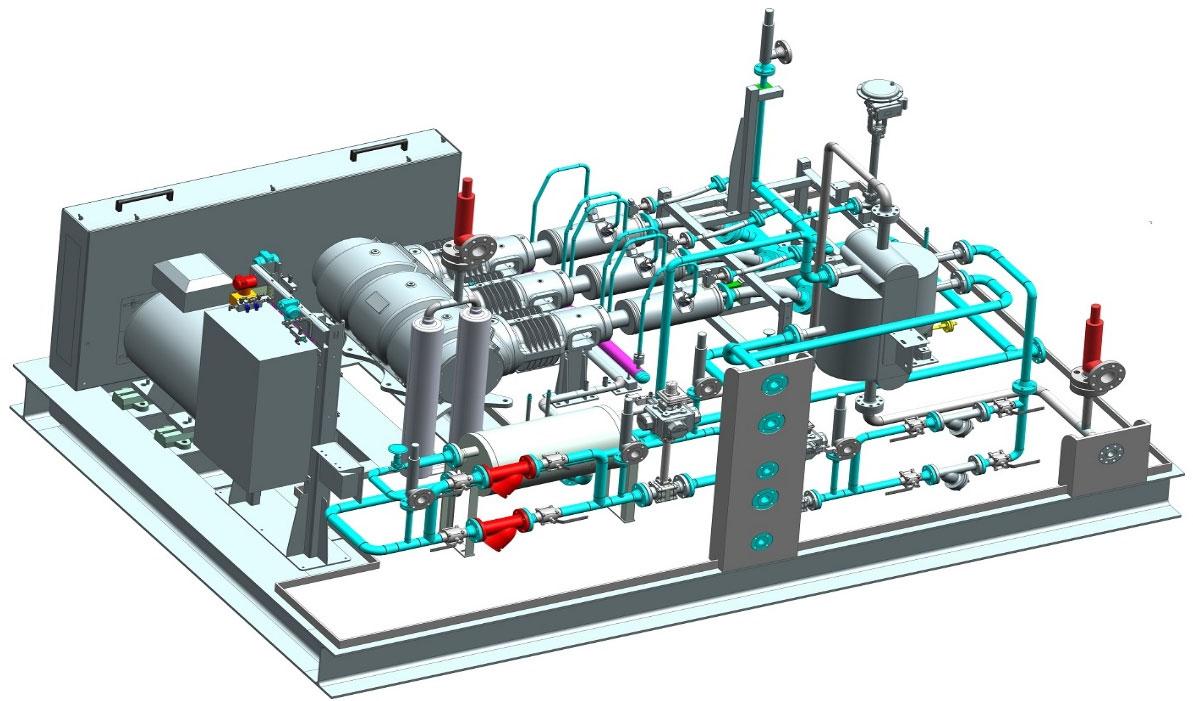
Figure 5: RECYCOOL integrated in the PVU unit
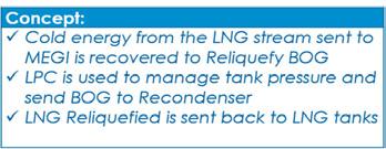
Figure 5: RECYCOOL integrated in the PVU unitFigure 5: RECYCOOL integrated in the PVU unit Concept : The otherwise wasted cold energy is stored inside LNG tank as a reserve for operating Concept : The otherwise wasted cold energy is stored inside LNG tank as a reserve for cost reduction, optimization of operation and safety. operating cost reduction, optimization of operation and safety.
Main system features Main system features
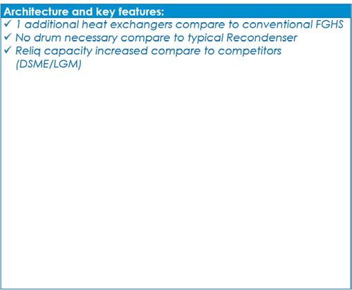
Recondensor is like a reliquefaction plant of excess gas – which helps to reduce burden on auxiliary engines and boil-off management. 5 Static equipment only: heat exchangers, valves… to be connected downstream existing low pressure compressors 5 Small footprint / compact system / easy integration 5 No additional rotating machines Main system features Recondensor is like a reliquefaction plant of excess gas – which helps to reduce burden on Recondensor is like a reliquefaction plant of excess gas – which helps to reduce burden on auxiliary engines and boil-off management. ‐ Static equipment only: heat exchangers, valves… to be connected downstream existing low pressure compressors 5 System reactivity / cool-down time reducedauxiliary engines and boil-off management. ‐ Small footprint / compact system / easy integration ‐ 5 Advanced control system for HP pump cavitation monitoring: Static equipment only: heat exchangers, valves… to be connected downstream existing ‐ No additional rotating machines 5 Compatibility with oil-injected screw compressorslow pressure compressors ‐ System reactivity / cool-down time reduced ‐ Small footprint / compact system / easy integration ‐ Advanced control system for HP pump cavitation monitoring: ‐ No additional rotating machines ‐ Compatibility with oil-injected screw compressors ‐ System reactivity / cool-down time reduced ‐ Enhancement of ship performance using PTO systems: ‐ 40 Advanced control system for HP pump cavitation monitoring: o Fuel savings ‐ Compatibility with oil-injected screw compressors This document is strictly confidential. Any unauthorised access to, appropriation of, copying, modification, use or disclosure thereof, in whole or in part, by any means, for any purpose, ‐ Enhancement of ship performance using PTO systems: infringes GTT’s rights. This document is part of GTT’s proprietary know-how and may contain trade secrets protected worldwide by TRIPS and EU Directives against their unlawful acquisition, use and disclosure. It is also protected by Copyright law. The production, offering or placing on the market of, the importation, export or storage of goods or services using Fuel savings GTT’s trade secrets or know-how is subject to GTT’s prior written consent. Any violation of these obligations may give rise to civil or criminal liability. © GTT, 2010-2022
5 Enhancement of ship performance using PTO systems: o o Fuel savings GHG emissions: methane slip reduced o GHG emissions: methane slip reduced o Fuel savings o GHG emissions: methane slip reduced o Aux. engines maintenance costs reduced o Fuel savings o GHG emissions: methane slip reduced o Aux. engines maintenance costs reduced o GHG emissions: methane slip reduced o Fuel savings o GHG emissions: methane slip reduced o Aux. engines maintenance costs reduced
Recycool: performance overview Recycool: performance overview Recycool: performance overview
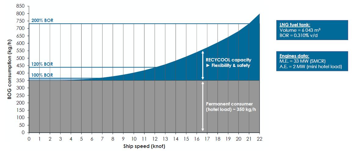
Figure 6: BOG management capacity with RECYCOOL for 7k TEU container vessel Figure 6: BOG management capacity with RECYCOOL for 7k TEU container vessel Figure 6: BOG management capacity with RECYCOOL for 7k TEU container vessel What we see on the figure 6 is the consumption vs ship speed. The genset consumption is constant (in grey). The quantity of BOG we can recondense (in What we see on the figure 6 is the consumption vs ship speed. The genset consumption is constant (in grey). The quantity of BOG we can recondense (in blue) will depend on the LNG flow consumed by the ME, which varies with the vessel speed. blue) will depend on the LNG flow consumed by the ME, which varies with the vessel speed. On this example for 7000 TEU vessel RECYCOOL is able to recondense half of the natural On this example for 7000 TEU vessel RECYCOOL is able to recondense half of the natural BOG at 15kts and 100% at 20kts. BOG at 15kts and 100% at 20kts. Figure 7: Example: 15k TEU / trade Asia-Europe Figure 7: Example: 15k TEU / trade Asia-Europe What happen if we put the same graph in the real life, with varying speed and varying gen-sets What happen if we put the same graph in the real life, with varying speed and varying gen-sets load? load?
What we see on the figure 6 is the consumption vs ship speed. The genset consumption is constant (in grey). The quantity of BOG we can recondense (in blue) will depend on the LNG flow consumed by the ME, which varies with the vessel speed. On this example for 7000 TEU vessel RECYCOOL is able to recondense half of the natural BOG at 15kts and 100% at 20kts.
Figure 7: Example: 15k TEU / trade Asia-Europe What happen if we put the same graph in the real life, with varying speed and varying gen-sets load?
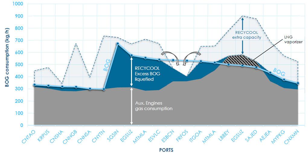
The recondensing capacity varies with the speed. This is the area between the dotted line and the gen-sets consumption (in grey). The BOG has its own variation, as it depends on the tank filling, the external temperature, and is represented in light blue line.
The recondensing capacity varies with the speed. This is the area between the dotted line and We can see on the figure 7 that the RECYCOOL recondense a good part of the BOG (in dark the gen-sets consumption (in grey). The BOG has its own variation, as it depends on the tank blue). We also see the periods where the gen-sets are sufficient. filling, the external temperature, and is represented in light blue line. We can see on the figure 7 that the RECYCOOL recondense a good part of the BOG (in dark Let’s focus on periods where BOG is higher than gen-sets and RECYCOOL combined. This can blue). We also see the periods where the gen-sets are sufficient. be handled in 2 ways: if it is a short time, just let the pressure rise, and use more recondensing Let’s focus on periods where BOG is higher than gen-sets and RECYCOOL combined. This capacity afterwards. Otherwise anticipate this low consumption period and send more BOG to recondenser beforehand. can be handled in 2 ways: if it is a short time, just let the pressure rise, and use more recondensing capacity afterwards. Otherwise anticipate this low consumption period and send more BOG to recondenser beforehand. So, we are always able to handle the BOG. So, we are always able to handle the BOG. Figure 8: Example: Ship trade : 15k TEU - 53 days - LNG bunkering SING If we push the study a little bit further and see the potential benefit for OPEX and emissions (figure 8). ME consume less and has less methane slip than 4-stroke engines. This is why PTO solution is gaining momentum. The OPEX reduction with a PTO can be around 2%, because you still use gen-sets often as the main BOG management solution onboard. Combining with RECYCOOL, the use of PTO can be maximised to reach 5% OPEX reduction and dramatic cut of gen-sets emissions.
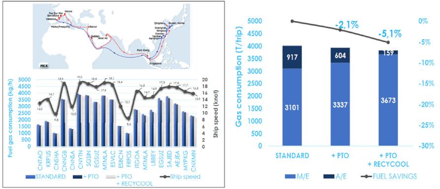
Figure 8: Example: Ship trade : 15k TEU - 53 days - LNG bunkering SING If we push the study a little bit further and see the potential benefit for OPEX and emissions (figure 8). ME consume less and has less methane slip than 4-stroke engines. This is why PTO solution is gaining momentum. The OPEX reduction with a PTO can be around 2%, because you still use gen-sets often as the main BOG management solution onboard. Combining with RECYCOOL, the use of PTO can be maximised to reach 5% OPEX reduction and dramatic cut of gen-sets emissions.
This document is strictly confidential. Any unauthorised access to, appropriation of, copying, modification, use or disclosure thereof, in whole or in part, by any means, for any purpose, infringes GTT’s rights. This document is part of GTT’s proprietary know-how and may contain trade secrets protected worldwide by TRIPS and EU Directives against their unlawful acquisition, use and disclosure. It is also protected by Copyright law. The production, offering or placing on the market of, the importation, export or storage of goods or services using GTT’s trade secrets or know-how is subject to GTT’s prior written consent. Any violation of these obligations may give rise to civil or criminal liability. © GTT, 2010-2022