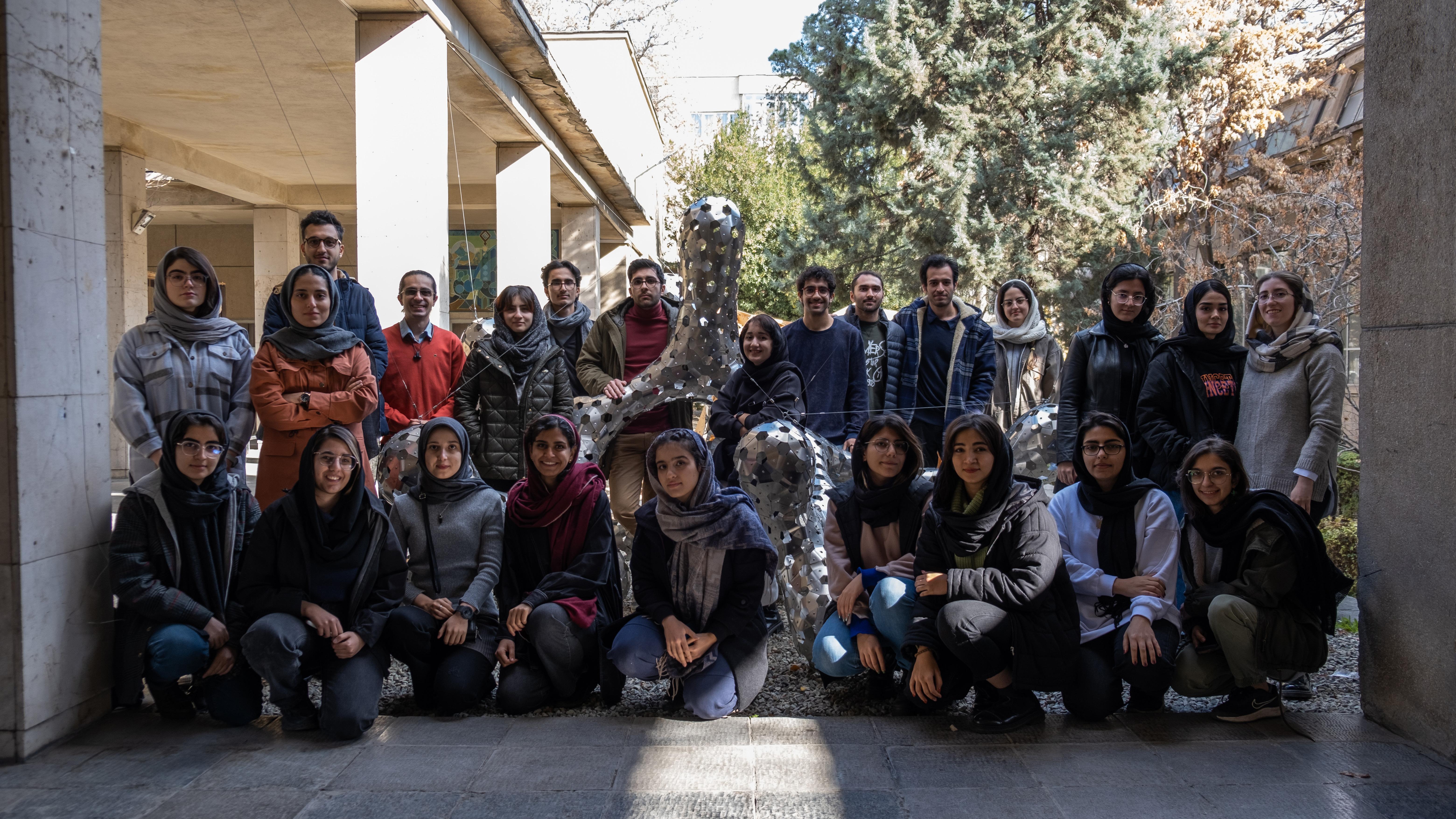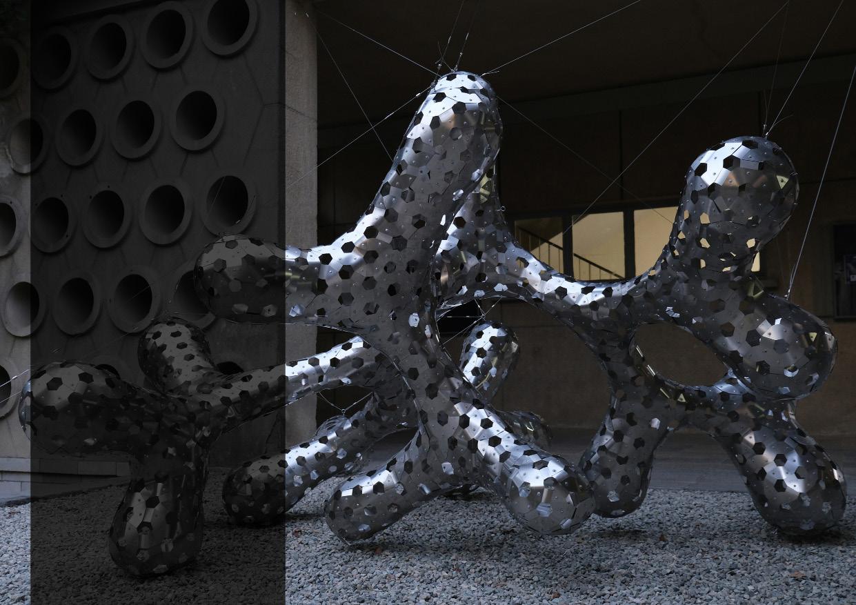



“Computer aided design and fabrication” course, held in Tehran University during the spring semester of 2023, aimed to introduce undergraduate students of architecture to the fundamentals of computational design and digital fabrication. In this course, students designed projects based on the theory knowledge they gained through the course. One of these projects was chosen by the students to be fabricated.
In the beginning of the course, it focused on the history of computational design and teaching the Grasshopper plug-in, in order to enable the students to use a parametric design tool. The students were then divided into groups of 3-4 to work on distinguished case studies and design a project of their own, based on the study. The next step was creating prototypes to find experimental solutions to their designs’ problems. Each group presented their prototypes to the class and voted for the best design. First selected design was omitted due to financial limitations and the second design was selected for further development and fabrication.
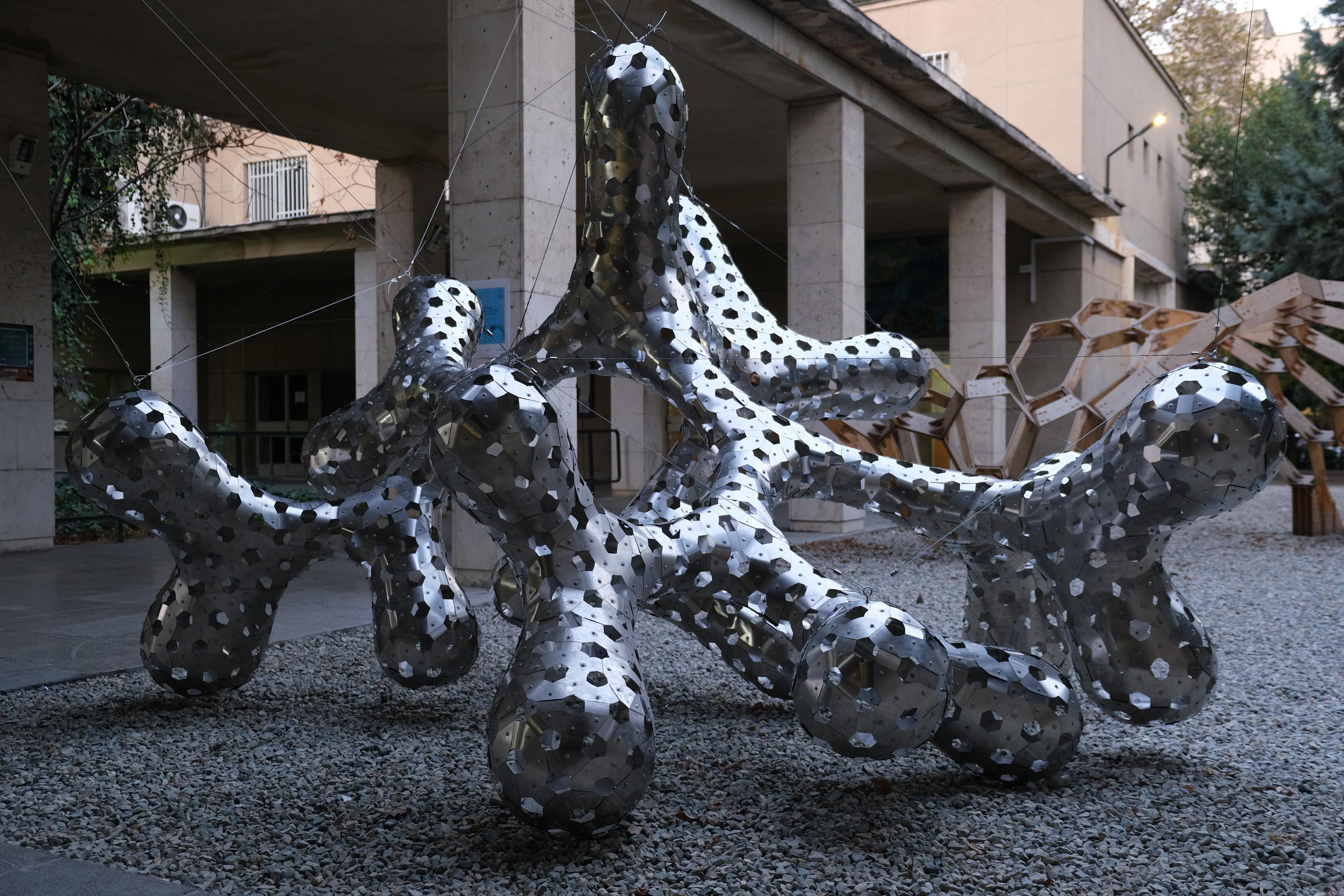
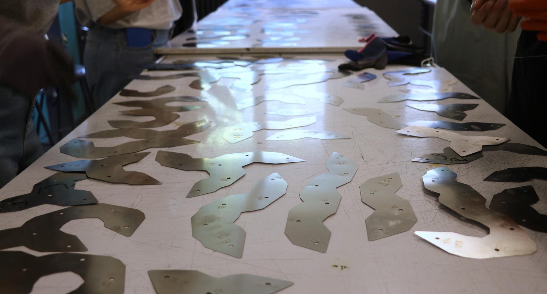
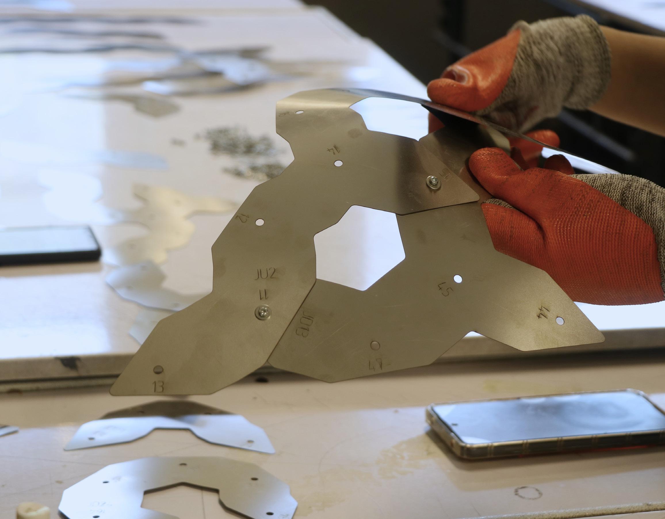
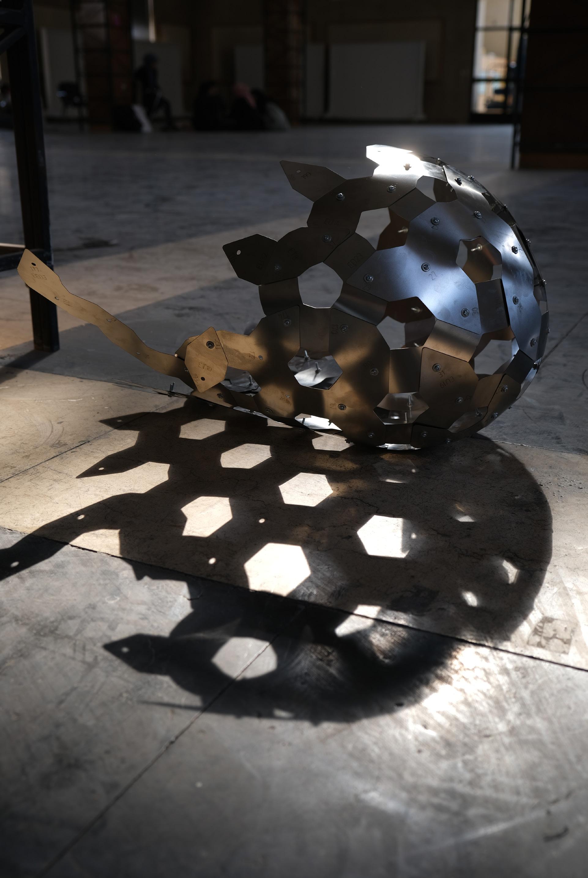
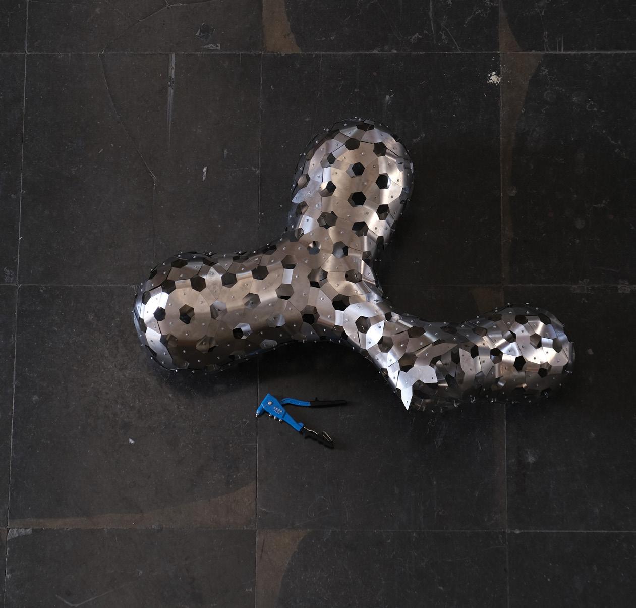
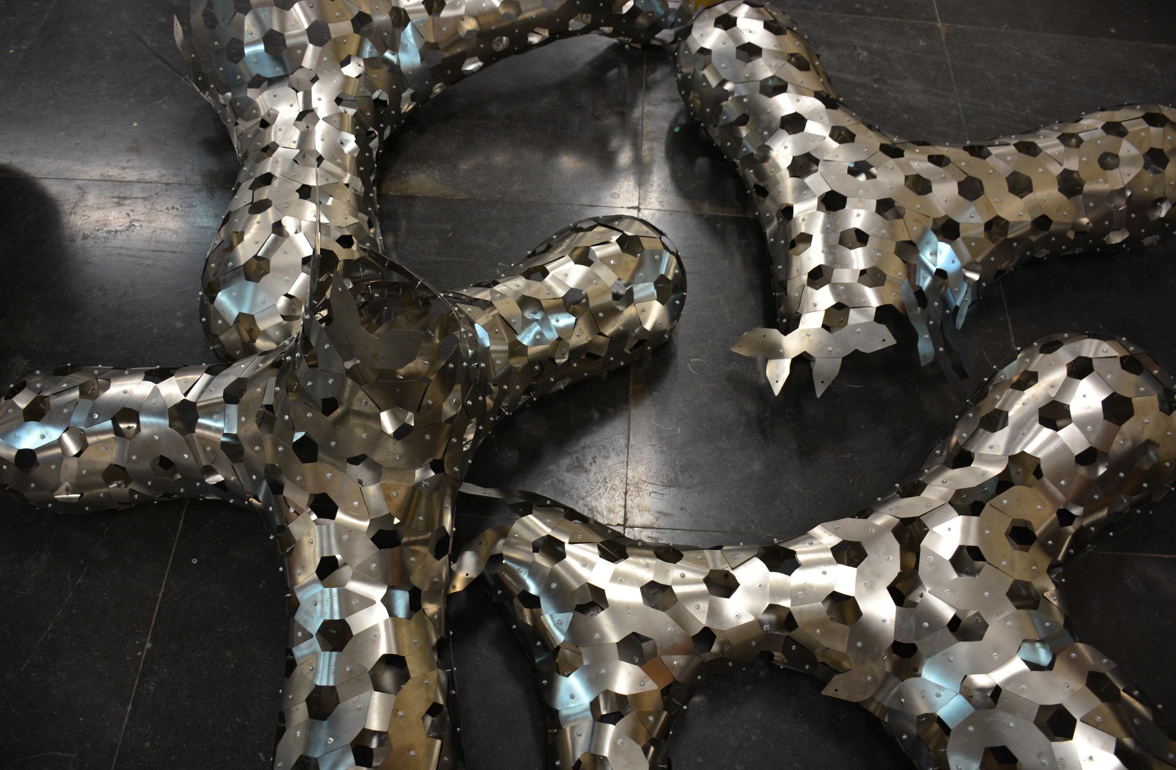
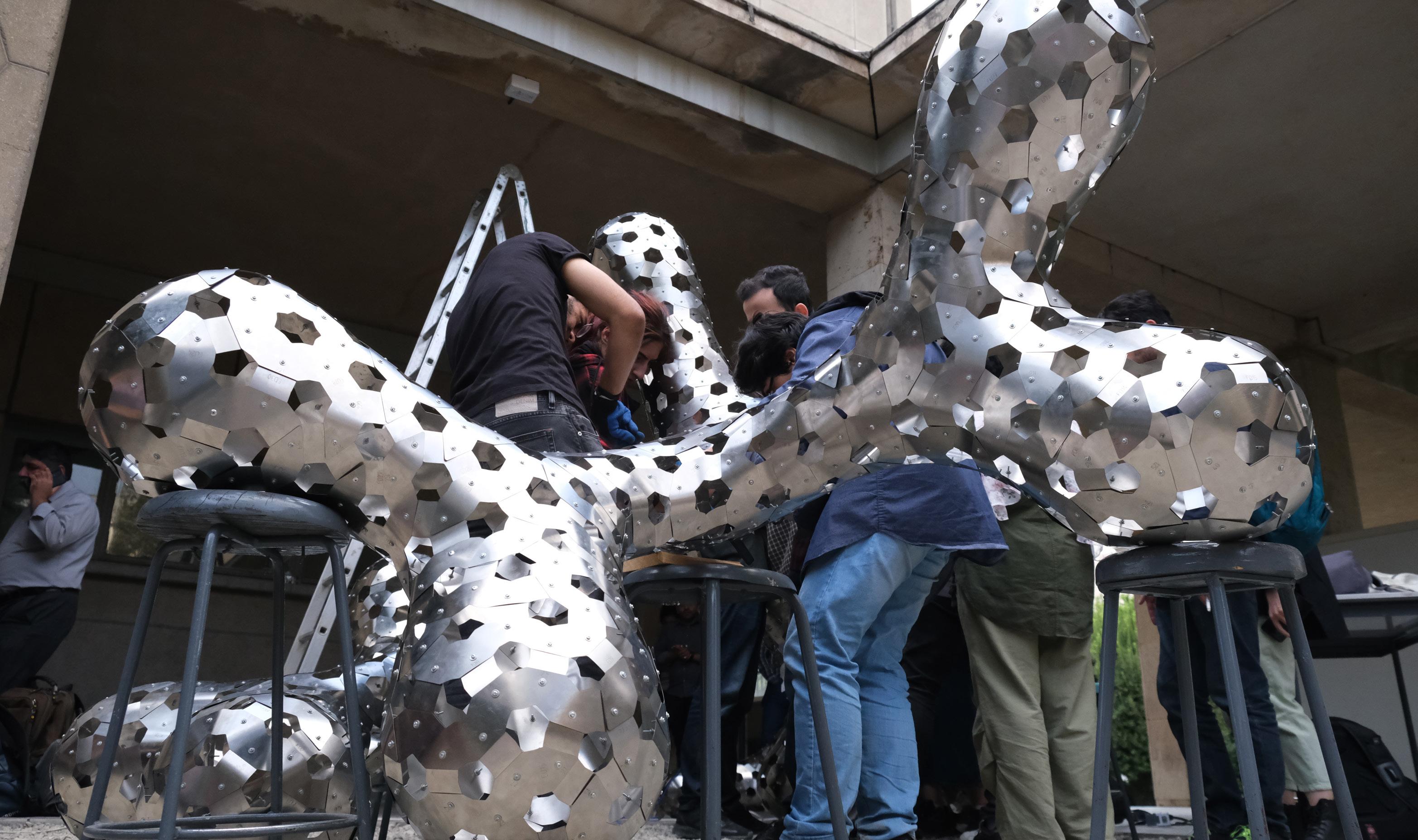
The design is formed based on bending-active concept. In this process for reaching the ideal stress tolerated in the form, spring steel sheets (thickness=0.3 mm) that were resilient in the bending range. Each slab with its unique shape, overlaps with others and shapes the final form, placed in three layers.
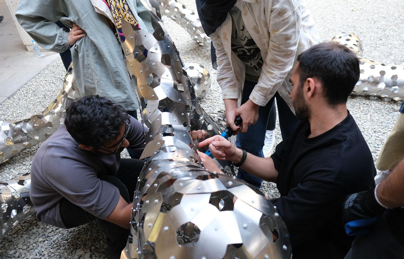
In this course parametric modeling, algorithmic thinking, team work, experimental fabrication and the experience to build in real-life scale and dealing with its challenges were made possible.



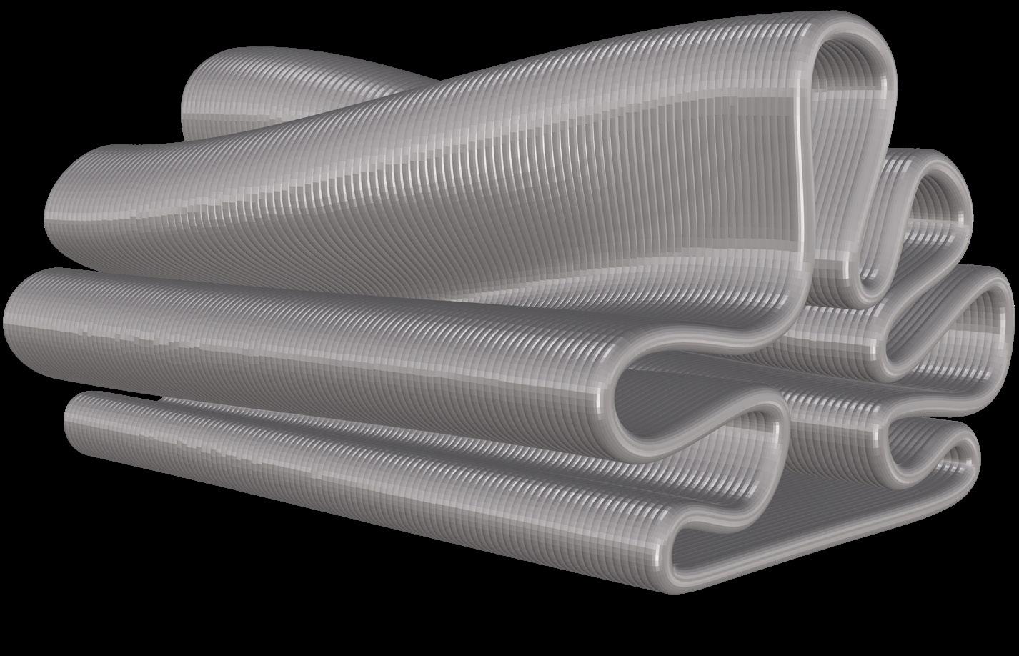
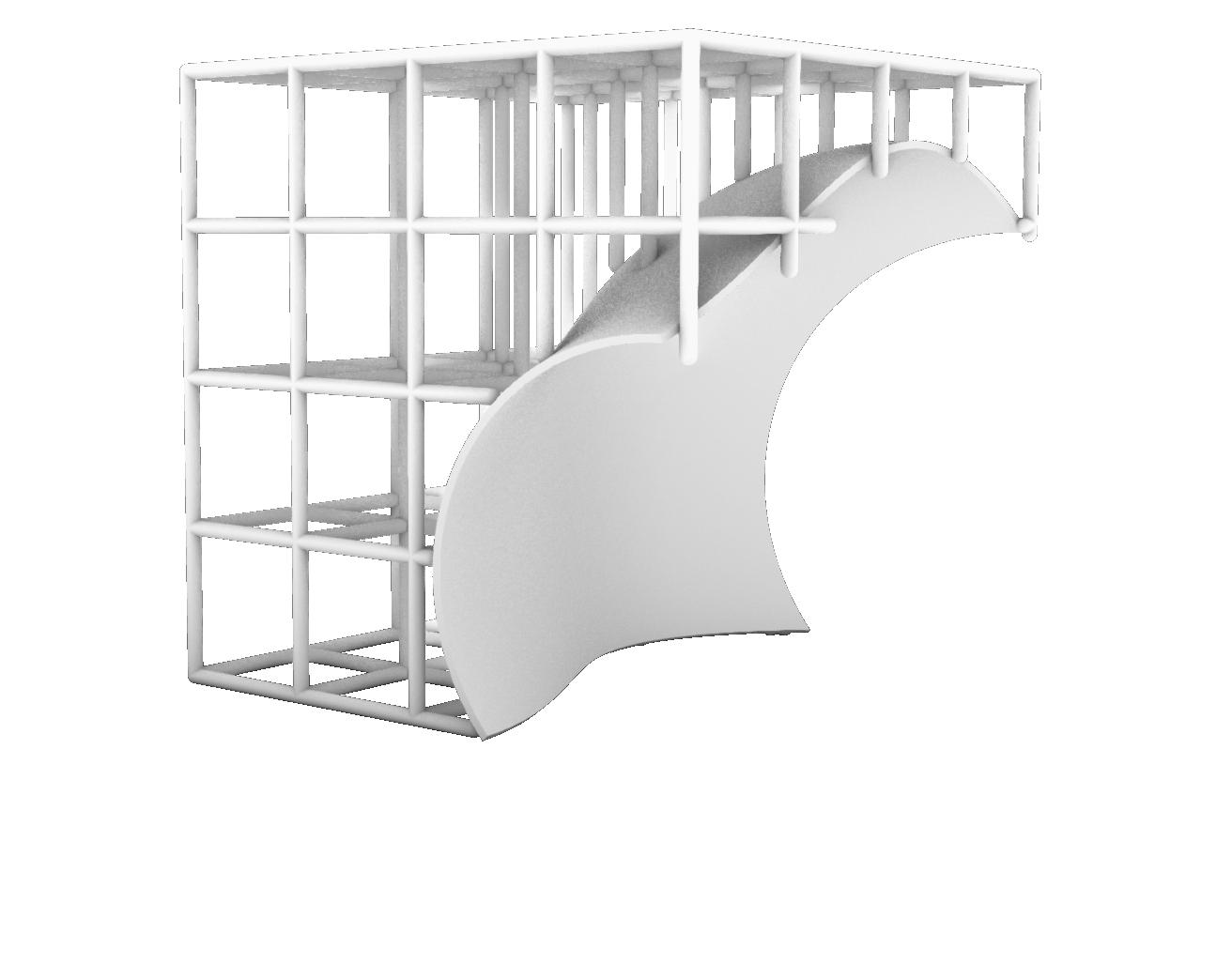


Geometry
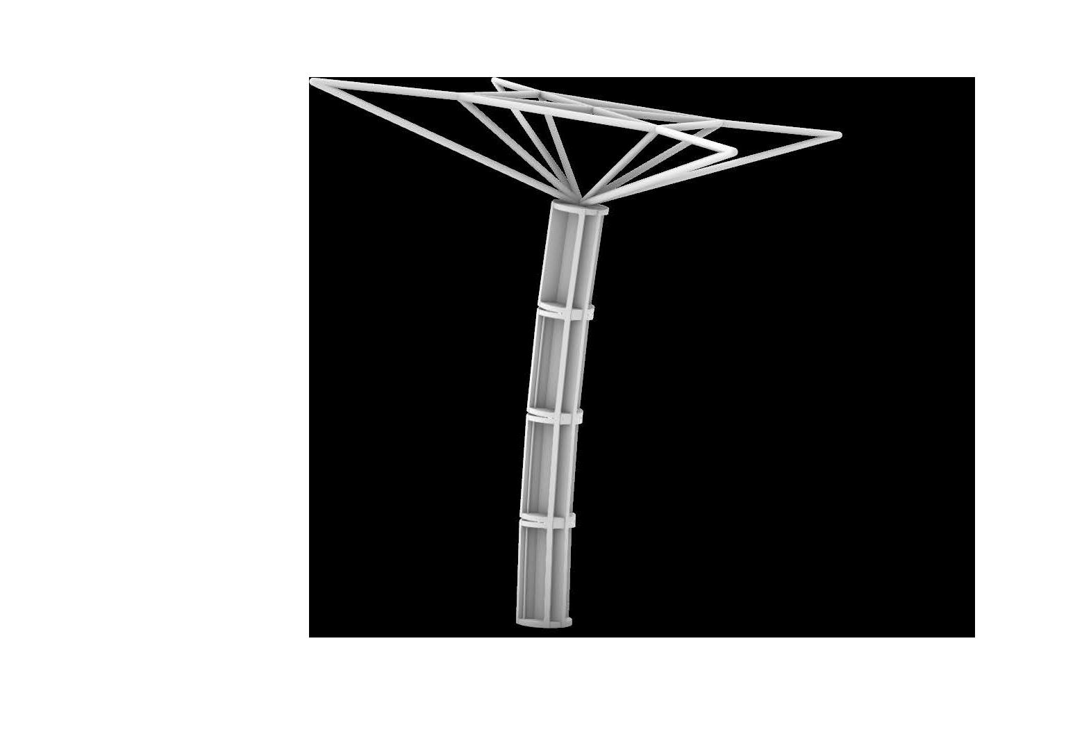
This form was inspired from Marc Fornes’ designs; initially a three-dimensional net consisting of linear components that turned into a ramal mass using multi-pipe and then for refining the form, the free end of the branches were curved.
In this project, one of the key features was the flexibility of the form. So, the construction logic of the design, is based on bending active structures; Using flexible material and using force to bend it, both defines the form and increases stress tolerance by the curve created.

Created Prototype by Electded Group:
Kiana Sadeghi
Samira Abedi
Atefe Irannejad
Construction Segments
The form and its complications lead to dividing it into plainer parts. The plainer parts, are strips which are joint perpendicularly (like the wrap and weft of fabric, but just put together not woven) and create the curve. So it was decided to use a flexible sheet and bolts and nuts as joining tools.

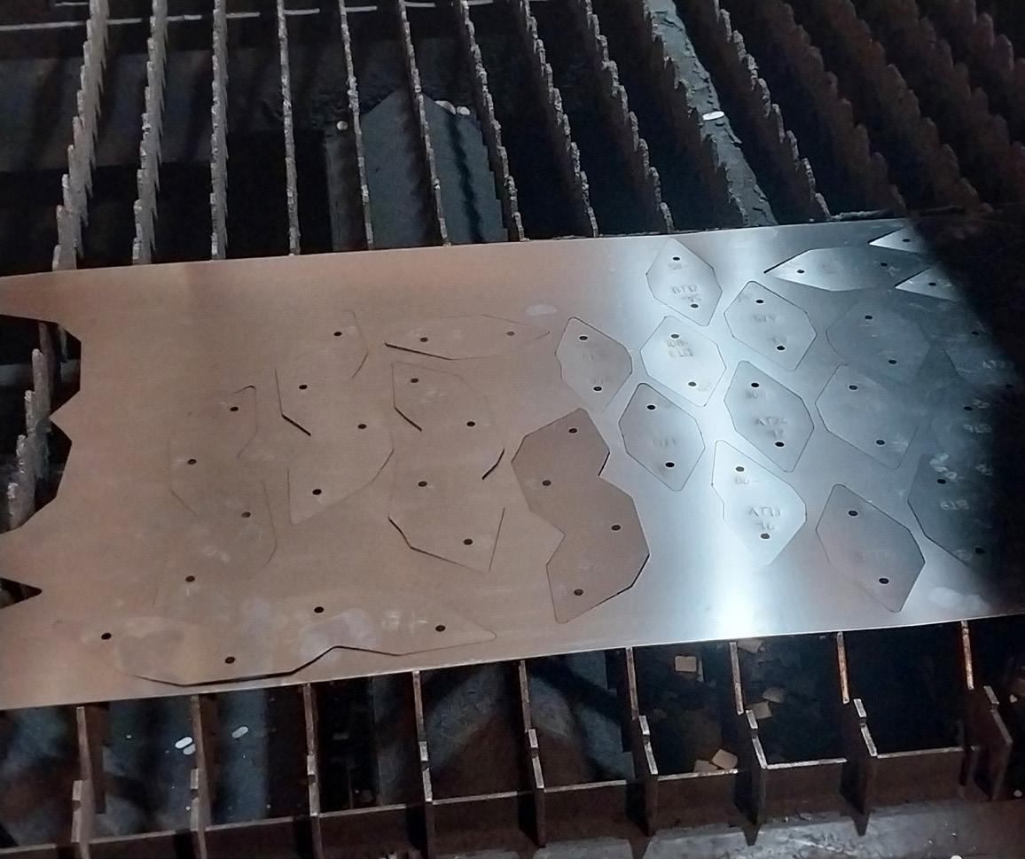
Choosing Materials considering the mechanical properties needed, spring steel 301 (thickness .3mm) was chosen. This material is anti-rust and anti-scratch; and due to its flexibility and resilience it just bends under pressure and won’t fold. This spring steel, is a sheet-base materialavailable as 40 cm wide rolls and can be cut depending on the size of the construction machine. Choosing the construction machine, always depends on the material. Since the chosen material was spring steel, steel cutting machine was used for slicing the pieces. The size of this machine was 1.2 x 2 m (being 2 meters was so useful reducing the waste of the material).
Fabrication Code
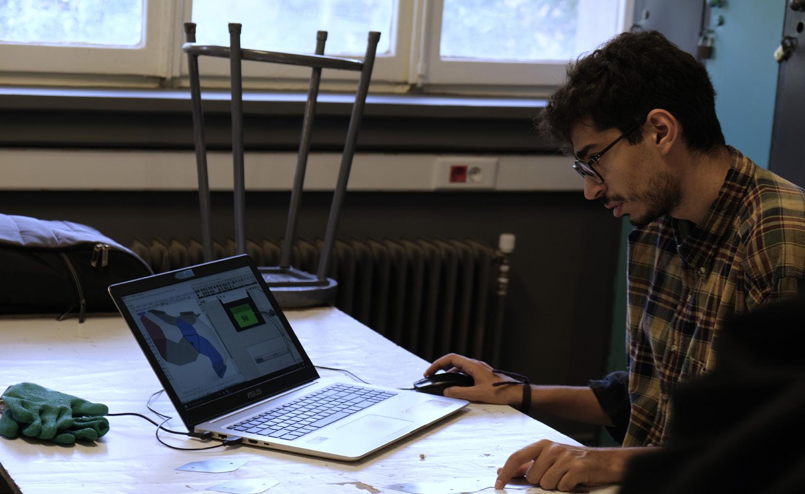
Breaking the polysrf of the form into ribbons with unroll, was done by Ivy plugin. Ivy does this by creating a graph on the triangulated mesh.
Polysrf triangulated mesh graph and weighting ribbons

The ribbons must be joint through two perpendicular rows to shape the form. And yet, these ribbons are not woven together, rather placed on top of each other and fixed using bolt and nut. So two upper and lower layers were created. In order to make sure they’re perpendicular, the lower layer graph should have been based on the upper layer graph. Which means the weight of the upper layer graph was used to create the lower layer graph.
1.
2.
3. Initial lower layer graph creating graph based on upper layer mesh weight ribbons based on the new graph
4. Checking the ribbons for overlapping faces
5. Comparing the ribbons with the initial mesh to find gaps which need a third layer. Creating a short graph for two faces ribbons of the third layer (this layer was created to increase rigidity and integrity)
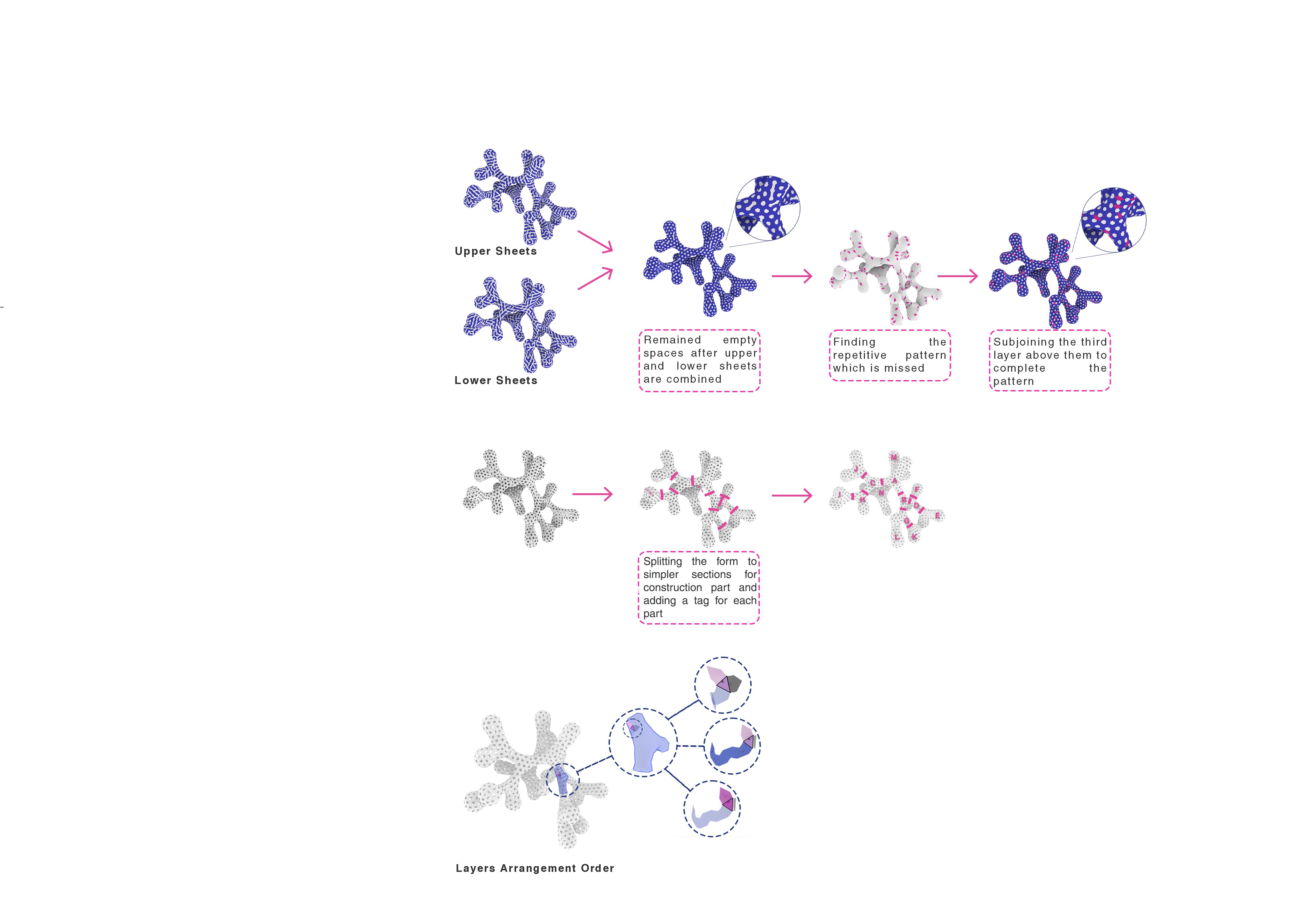
The ribbons must be joint through two perpendicular rows to shape the form. And yet, these ribbons are not woven together, rather placed on top of each other and fixed using bolt and nut. So two upper and lower layers were created. In order to make sure they’re perpendicular, the lower layer graph should have been based on the upper layer graph. Which means the weight of the upper layer graph was used to create the lower layer graph.






Instructor: SeyedAli Derazgisoo
Tutor: Mona Lavasani, Yaser Karimian
Primary Code: Kiana Sadeghi
Code and Final Fabrication: Mona Lavasani
Booklet and Video team:
Asal Amirbozorgi
Bardia Kaj
Faranak Abbasi
Fateme Qasemi
Kimia Ghasemi Monfaredrad
Kiana Sadeghi
Nazanin Zahra Mahmoudi
Parnian Akhtardanesh
SeyedAli SeyedArab
Tarlan Hashemi Naji
Class Members & Final Fabrication Attendance:
Amir Sabouri
Atefeh Irannejad
Bardia Kaj
Danial Danaei
Donya Alipour Vaezi
Fateme Qasemi
Mohammad Ali Aslaminezhad
Kiana Sadeghi
Kimia Ghasemi Monfaredrad
Melika Sadat Mirseifi
Parnian Akhtardanesh
Razieh Esmaili
Samira Abedi
Sayyed Hesamoddin Mir
SeyedAli SeyedArab
Tarlan Hashemi Naji
Zahra Afkhami
Final Fabrication Attendance:
Alireza BohloulBandi
Amir Ansarypour
Aram Ebrahimi Yazdi
Asal Amirbozorgi
Ehsan Goodarzi
Elahe Bahrani
Elham Miralavi
Faranak abbasi
Foad Alaei Tafti
Mohammad Mahdi Lolachian
Nazanin Zahra Mahmoudi
Negar Kazemi
Parnika Babareza
Seyedeh Sarah Banaderi
Seyedeh Zahara Saadat
Helpers:
Fateme Joola
Mahsa Shiari
Negar Niknezhadi
Saba Soltani
Special thanks to Dr.Hamed Mazaherian, Administrator of college of fine arts, for helping to set the location of monument and Yaser Karimian for the preparation of monument’s final appearance.
