MICHELLE SCHNEIDER Architectural Portfolio 2011-2023
*
Specificity of roles within projects can be found at the beginning of each project synopsis.
CONTENTS: 10 PETCOKE HOUSEY HOUSE A HOUSE ON FIRE ISLAND FOUNTATION HOUSE FARM STRAWBERRY MANSION POWER STACK: GRADUATE THESIS THE FOREST + THE FILTER 04 OF DOORS, OF AIR 12 16 20 36 40 42 24 MEDMODULAR CROWN HEIGHTS BROWNSTONE 26 PRESIDENT STREET TOWNHOUSE 30 34 OBSERVATORY HOUSES 3
OF DOORS,
OF AIR
Houston, TX
Fall 2020
The door’s phenomenological and formal qualities draw air at both the human and building scale. The building designed from such qualities both creates a distinct contrast between an open and closed space condition, but is also capable of serving as a commentary on its surroundings, namely air, through the program spaces, and through the program spaces between the program spaces; it can blur the lines between open and closed. This formal logic and experiential effort results in a building that is capable of drawing air according to the program’s parameters, and the user’s experience of the air conditions generated by the building, all of which stem from the arc of the door swing.
The Cultural Center itself is a grouping of 3 structures, the main building, the admin building, and the wind pavilion. Each is situated according to its needs of separation from other structures through the logic of the air on site. The Center performs at different scales of porosity: the spatial organization on site, purposeful spacing between the pieces of program within the building to elaborate upon the air and its characteristics, & the ever changing state of the doors.
The wind on site is incredibly unpredictable. To combat this unpredictability, it was natural to put doors everywhere.
 Academic Individual Project Professor: Liz Galvez
1 _ KEY AXONOMETRIC
4


4 _ FIRST
PORTFOLIO MICHELLE SCHNEIDER
FLOOR PLAN
3 _ MAIN BUILDING SECTION
5
2 _ WIND PAVILION PLAN


2020 _ ACADEMIC OF DOORS, OF AIR
2
6
1 _EXTERIOR ELEVATION
_VIGNETTES


PORTFOLIO MICHELLE SCHNEIDER
3 _ BUILDING MODEL
The metal panels used for facade treatment wrap the ground and extent to a neighboring building, curating the user’s experience within the alleyway of light and dark, sun and shadows.
4 _ PAVILION MODEL
7
The wind pavilion is a sculptural piece in the NorthEast corner of the site.
2 _ CLIMATE PERFORMANCE / RESPONSE


The building’s porosity serves to maintain the ability to utilize the existing weather conditions, with the aid of the meteorological lab that is situated within the building on the fourth floor. The doors are mechanically controlled according to a series of acceptable climates per programmatic element. For example, if it is 72 degrees and sunny, the gallery can accommodate this and fully opens its doors to eliminate the separation of air on site from air in the gallery. The orchestration of the doors is fully flexible and able to change as needed per the atmospheric conditions and the fairly flexible ‘ideal’ climate of each space.

2020 _ ACADEMIC OF DOORS, OF AIR
8


PORTFOLIO MICHELLE SCHNEIDER 9
THE FOREST +
THE FILTER
Academic Group Project: Jane Van Velden
Professor: John Casbarian + Fedrico Pedrini (XDGA)
Paris, France
Spring 2022 - Awarded Fossi Prize
- Equal parts conceptual, all graphics included are my own.Sited on the Saclay plateau, our project serves as the built threshold between the forest and campus. The forest operates as the filter through which one moves from the small residential scale of the town below, to the monumental scale of the still-growing campus. It synthesizes the perimeter condition of the channels with the filter-like qualities of the forest. Dominated by young, transient students and workers who leave the campus often vacant, a missing element of the campus ecology is a more permanent presence of people. We aim to provide housing that supports populations that are in more diverse, yet stable, stages of their lives. Specifically, families. The architecture will provide an
infrastructure that is parallel to the ‘natural’ ethos that our design enforces with an educational component that intertwines nature with learning at all stages of life. The physical perimeter of the school will be inherently fuzzy, blurring the boundaries between interior and exterior, domestic and public. A synthesis of the developmental ethos of open-air and forest school models, this will serve as the charge of the project; the reason families move here, stay here, and grow here. A continuous landscape strategy unites a combination of housing typ-ologies and forest school. The pathway alongside the screen, the pinch points of the residential bars, and the ground floor become the space of the collective.

10
1 _ SITE CONDITIONS
We explored the relationship between nature and artifice, studying the network of man-made ditches; a trace of the development through time, that can be read at the scale of infrastructure and embodied experience.


PORTFOLIO MICHELLE SCHNEIDER 11
PETCOKE
Academic Individual Project Professor: Brittany Utting Houston, TX Spring 2021
An institute for New Ecologies, this is an experimental facility whose charge explores the petrochemical byproduct petcoke. The institute seeks to create a new infrastructure and institution that drives the public education of current energy systems, particularly the petrochemical ecologies that fuel Texas, and incubate a new, forward looking ecology that will host the cultural and physical shift towards more responsible energy procurement practices. It enables proper storage of petcoke and houses its respective machinery for material processing and studying. It is a mediator that facilitates negotiation between the surrounding petrochemical industries and those who advocate for the environment and greener energy alternatives.
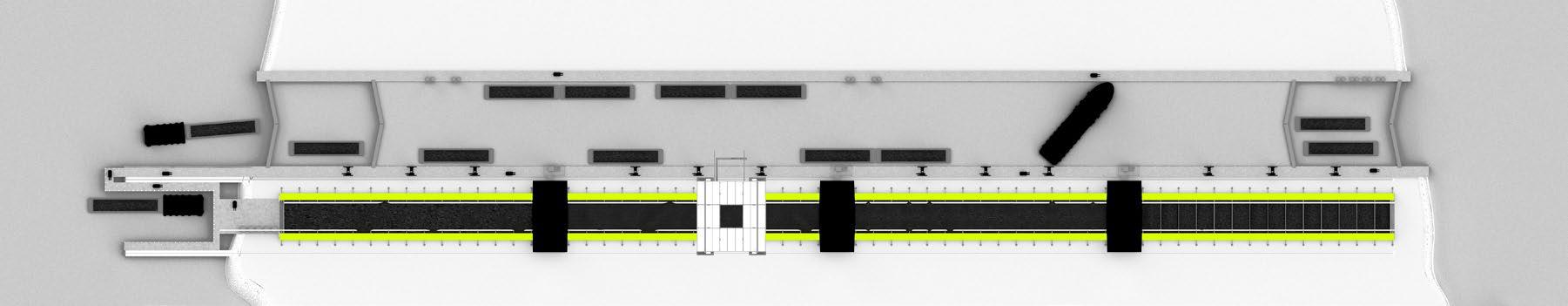
The linear petcoke facility houses residential units arranged along the thick storage basin walls, the institute accommodated by a gantry, and processing station nodes. A canal and lock system is cut through the island site, parallel to the facility, where freight barges, tugboats, and ships can deliver, transfer, and pick up the material. For those living and working inside, mountainous landscapes supplied by the heaps of animated petcoke float by day to day, moved by conveyors, barges and cranes. The facility provides a new means of living with the dirty aspects of the Anthropocene era; as architectural theorist and philosopher Helene Frichot would say, its imperative that we cope with our dusty, dirty, defiled world.

12


PORTFOLIO MICHELLE SCHNEIDER 3 _ PLAN 2 _ SECTION 1 _ SITE PROCESS PLAN 13


2021 _ ACADEMIC PETCOKE
1 _ GANTRY PLAN
2 _ EXTERIOR RENDERING 1
Excess petcoke collection system built into building form.
3 _ EXTERIOR RENDERING 2
Architectural, infrastructural, educational complexities and confrontations.
4 _ EXTERIOR RENDERING 3
14
Self cleaning fenestration systems for housing.
A cleaning threshold in the form of

Highly efficient HVAC and dust collection devices enable living with manmade toxicity. Collective isolation require new methods of living.


Living with our toxicity, ruminations on a superficial rinsing of inhumane practices.

PORTFOLIO MICHELLE SCHNEIDER
6 _ INTERIOR RENDERING 1
a vestibule ensures safe living spaces.
5 _ LIVING IN PRECARITY
7 _ INTERIOR RENDERING 2
Juxtapositions of interior gardens and dining, with elements of the context.
8 _ INTERIOR RENDERING 3
15
HOUSEY HOUSE
Academic Group Project: Maggie Martin
Professor: Andrew Colopy
Houston, TX
Spring 2021 - Awarded Fossi Prize
- Groupwork equal parts conceptual and graphic workHousey House situates itself as a product that addresses the real world problems with current unsuccessful methods of home ownership regulations, and serves as a critique of housing accessibility through the ADU. Though the project can be viewed from a multitude of lenses, including home equity, iconography, and adaptability, its strength lies in its economic identity. This ADU serves as an architectural tool meant to embrace economic diversity by touting an extremely low starting cost, while simultaneously possessing a design that can support further improvements. Housey House can be purchased from any hardware store or builders magazine. It is prefabricated and purposely petite for simplified shipping, arriving in the form of 3 modules that contain the bedroom, bathroom, and kitchen. The ADU is positioned at the corner of the site nearest to the driveway, where the
modules that contain the bedroom, bathroom, and kitchen. The ADU is positioned at the corner of the site nearest to the driveway, where the modules spread across the site based on a public visibility logic. Between the three modules lies an infill space, where the owner holds creative liberty to expand upon the decking the ADU kit requires. With such a small starting cost as well as new ordinances to be embraced by the city, the opportunity for home ownership is expanded to the larger population. Housey House aims to empower the person that lives within it, with choice, driven at its core, by economic variety. It pushes against the current reality, being that the present issues with ADU’s is that there is no mechanism for home ownership; it exemplifies how urban densification can be modestly achieved through contemporary industrialization. For a modest $78,000 get Housey House at your local hardware store soon.

16


PORTFOLIO MICHELLE SCHNEIDER
1 _ PLAN EXAMPLE 1
2 _ PLAN EXAMPLE 2
17
3 _ PLAN EXAMPLE 3


2021 _ ACADEMIC HOUSEY HOUSE
1 _ MANUFACTURING
2 _ VENDING
18
3 _ IMPLEMENTATION
This project took advantage of current production and construction methods en masse, without sacrificing opportunites for personalization of the home.


PORTFOLIO MICHELLE SCHNEIDER
4 _ HOUSING DENSITY LANDSCAPE
19
A HOUSE ON
FIRE ISLAND
Professional : Coughlin Architecture

Built Fire Island, New York Fall 2016
- I entered the project as it began construction and my involvement continued through to its completion. I served as architectural photographer for documentation and publication, as well as aided in overseeing site meetings with both the contractor and client throughout the entirety of the construction process. I collaborated with Paul Coughlin on the schematic layout and produced the construction drawings for the outdoor shower and garden spaces, which was built a year after the house’s completion. Additionally, I made the graphic decisions and produced representations to illustrate design intents and for further architectural discourse regarding the project and its role in Fire Island. -
Situated on architecturally historical Fire Island, this is a 4-bedroom seasonal home. It is placed on the site to take advantage of the sun, wind and views of both the ocean and bay. The “L” shape of the house creates a private enclave of exterior space to blur the line between indoor and outdoor space. Functionally, the first floor is split at the entry into a south-facing living dining and kitchen zone, and a westfacing guest wing. Bedrooms and a den are located on the second floor. A modest roof deck allows for unobstructed sunset and sunrise views. Clad primarily in carbonized black siding, cuts, voids and punches are composed with windows, recesses and overhangs for seemingly unorganized facades.
1 _ REAR ELEVATIONAL ISOMETRIC
20


3 _ SECTION Scale: Not to scale 0’ 2’ 4’ 10’ 2 _ FIRST FLOOR PLAN A - Living B - Dining C - Kitchen D - Stair E - Entry F - Powder G - Bathroom H - Bedroom I - Deck J - Pool PORTFOLIO MICHELLE SCHNEIDER 21
Final architectural photography shot + edited myself for documentation, website, and online publication purposes.


 1 _ FINAL ARCHITECTURAL PHOTOS
2016 _ PROFESSIONAL A HOUSE ON FIRE ISLAND 0’ 2’ 4’ 10’ 2 _ SECTION 22
The layout of the house is extremely planar. I found it most complementary to output representational images that put emphasis on this design component, rather than viewing the project from any sort of typical perspective projection. This allows the viewer to experience a massive amount of planes simultaneously, while still in rectilinear form.

 4 _ PARALLEL PROJECTION REAR ELEVATION
PORTFOLIO MICHELLE SCHNEIDER 23
3 _ ISOMETRIC FRONT ELEVATION
OBSERVATORY
HOUSES
Professional : Coughlin Architecture
Competition Entry
Roccascalegna, Italy
Summer 2017
- Paul Coughlin and I worked together to come up with a design concept, I produced the graphics individually.Diagrammatically, a constellation is a series of points connected by lines; organization can be found within the man-made and natural realms of Roccascalegna. Pointlike elements are positioned within the landscape, linear elements serve as the meeting grounds between points; the point elements anchor each piece of Roccascalegna. The constellation of our proposal: The sky lounge is set
reflects the night sky. The units pay homage to the village of Roccascalegna through its collective massing. The thickness of the housing structure’s envelope borrows from the masonry walls of the castle. Tiny openings in the structure’s facade, reminiscent of arrow slits, are scattered across the geometry like stars in the night sky. The thick walls in plan, previously used for defensive purposes and structural stability, create a contrast between the intimate interior domestic space and the vast exterior around the
24
Using the idea of celestial constellation, we mirrored the way stars are points in space with linear connections to create a whole.

The Skylounge contains program that will be necessary to every user of the resort. These programmatic pieces are placed within the castle’s existing point-like spaces.


The cylindrical observation spaces serve as the points within the housing, as they are the space that will most directly and fully allow the users to stargaze.
 1 _ CONSTELLATION OF SKY
2 _ CONSTELLATION OF SKYLOUNGE
3 _ CONSTELLATION OF HOUSING
1 _ CONSTELLATION OF SKY
2 _ CONSTELLATION OF SKYLOUNGE
3 _ CONSTELLATION OF HOUSING
PORTFOLIO MICHELLE SCHNEIDER 25
MEDMODULAR

Professional : Coughlin Architecture
Schematic Design/Built
Philadelphia, Pennsylvania
Spring 2017
- My role within the following project occurred at all levels and was highly-involved. When we first received the idea from the client, Paul Coughlin and I completed several iterations of the room units and after insight from medical professionals, we settled on the single, double, M.R.I. and operating rooms. I aided in the production and design decisions for the schematic drawings, as well as produced every graphic element of the project, including showroom banners. -
This modular design project is developed for the acute care provider, MedModular. The modular units are intended to feed parallel hospital prototype projects current under development with MedModular. All room typologies are designed interchangeably and can be inserted and constructed in any variety of combinations and types with a variety of finishes. Rooms are assembled
in a factory in a repeatable process and can be customized and standardized for all healthcare settings and end users. Units are then flat-packed and shipped to locations world wide, faster and more cost effective than traditional site construction.
The showroom, redone light and minimally, ensures the primary focal point is the flat pack construction singlepatient hospital unit it contains. The secondary focal point of the space are the walls, which are lined with banners explaining MedModular from its multiplicity of room types and implementation, to its large scale construction and implementation. The patient room prototype was constructed in Finland by ADMARES.
Three building concepts were created: low, medium, and high rise.
1 _ UNIT PROTOTYPE 26
2 _ SINGLE UNIT EXPLODED AXONOMETRIC

a1 - bathroom
a2 - cabinetry
a3 - ceiling finish
a4 - lighting
a5 - ceiling frame
a6 - ceiling insulation
a7 - top enclosure
b1 - door
b2 - wall insulation
b3 - wall frame
b4 - outer finish
c1 - inset screen
c2 - interior finish
c3 - wall insulation
c4 - wall frame
c5 - ext wall enclosure
d1 - finished flooring
d2 - subfloor
d3 - floor insulation
d4 - floor frame
d5 - bottom enclosure
e1 - seating
e2 - interior finish
e3 - electrified glazing
e4 - window frame
e5 - wall insulation
e6 - wall frame
e7 - facade panel
f1 - interior wall
f2 - wall insulation
f3 - wall frame
f4 - ext wall enclosure
3 _ BUILT PROTOTYPE
The built prototype, fully assembled. Care was taken to ensure sterile spaces and construction details. Currently on view in Philadelphia.
Photo taken + edited myself for documentation, website, and publication purposes.

PORTFOLIO MICHELLE SCHNEIDER
27


2017 _ PROFESSIONAL MEDMODULAR
3 _ HIGH RISE ASSEMBLY PLAN
2 _ HIGH RISE ASSEMBLY SECTION
1 _ HIGH RISE ASSEMBLY
28
The high-rise, one of three different assembly models, is envisioned to be in a high density urban area.


PORTFOLIO MICHELLE SCHNEIDER
4 _ MODULAR ASSEMBLY MODEL
This model was used to show the process through which the building is assembled. The flat pack rooms are received, constructed, and hauled to site. They are then hoisted into place.
5 _ MODULAR ASSEMBLY MODEL
29
A model for client EIR Healthcare, being shipped to New Orleans for HCD Expo.
CROWN HEIGHTS
BROWNSTONE
Professional : Coughlin Architecture Under Construction Brooklyn, New York Spring 2020
- My role in the following project was the project manager. I aided in making schematic design decisions, producing the construction set including plans, sections, rcps, material takeoffs, schedules, demo and details, and the entirety of the graphic work. I also interfaced with the client, the engineers, and the contractors for the bidding process.The project is located in the Crown Heights neigbhorhood of Brooklyn. The design transformed the two family
home into three units, through the addition of another level and a 7’ extension onto the rear of the brownstone. Keeping with the existing character of the building particular to the brownstone context, the facade was kept largely the same, save for the additional story on the third level. The extension on the rear of the building also provided an opportunity for each unit to have a private patio. The addition and extension for the building is to be constructed out of corrugated metal

30
1 _ ROOF PLAN
The roof shows the new bulkhead, the coordination of required solar panels, fire access, a new roof deck for tenants, and the modern and newly occupiable roof from what once was a non-accessible asphalt roof space.
The plan shows the 7’ rear addition, as well as a main bedroom that now has access to a front patio space built from the brownstone detailing.
ELEVATIONS AND MATERIAL TAKEOFFS
Coordinated with a window schedule, the elevations notate the existing conditions and the new additions and the final facades.
PORTFOLIO MICHELLE SCHNEIDER QUEEN QUEEN UP 20R DN 18R BEDROOM 310 HALL 301 STAIR 300 LIVING ROOM 304 KITCHEN 305 BATHROOM TYPE 3 306 BEDROOM 309 BATHROOM TYPE 4 307 BEDROOM 303 LAUNDRY 311 W.I.C. 302 W.I.C. 308 TWIN 30'-0" 100'-0" 20'-0" BALCONY P 40 7'-0" 11'-2 15'-3 FPSC 36"x6" AL. BAR GRILLE PTD. WHITE TYP. 3 REF. MECH. 5'-6" 5'-6" 6'-0" 10'-6" 5'-6" 3'-2" 3'-2" 3'-2" 8'-3" 8'-3" 4'-8" 3'-0" 9'-6" 8'-10" 2'-0" 10'-71 4'-0" 4'-5" 5'-4" 14'-3" 2'-0" 18'-0 3'-9" 6'-6" A A A D C B A C D A D 1 3 4 1 X1 X1 3 X1 3 3 1 3 3 3 X1 X1 X1 X3 X2 X1 X2 4 3 3 10% LT. REQ'D 16.46 SF PROVIDED. 79.43 SF W.A. 5% VENT. REQ'D: 8.23 SF PROVIDED: 26.48 SF. 164.69 SF 10% LT. REQ'D 10.71 SF PROVIDED. 19.42 SF W.A. 5% VENT. REQ'D: 5.36 SF PROVIDED: 19.42 SF. 107.08 SF 10% LT. REQ'D 10.16 SF PROVIDED. 28.58 SF W.A. 5% VENT. REQ'D: 5.08 SF PROVIDED: 9.55 SF. 101.56 SF 10% LT. REQ'D 11.89 SF PROVIDED. 58.21 SF W.A. 5% VENT. REQ'D: 5.95 SF PROVIDED: 29.11 SF. 118.99 SF 2 8 2 10 8 2 10 8 (2) 2 10 8 3 8 10 8 210 80 (2) 2 8 (2) 1 8 2 8 2 8 (2) 6 7 EXST'G MASSING PARTY WALL EXST'G MASSING PARTY WALL 04|A401 07|A401 06|A401 06|A400 09|A400 07|A400 08|A400 01|A400 02|A400 04|A400 03|A400 REF A401 FOR KITCHEN PLAN + ELEVATIONS REF A400 FOR BATHROOM PLAN + ELEVATIONS REF A401 FOR KITCHEN PLAN + ELEVATIONS 3 8 TAG 14'-1112 3'-0" 5'-0" 2'-1" 5'-0" 52'-0" EXISTING 7'-0" 36'-0" EXTENSION 1" SEISMIC SEPARATION 1" SEISMIC SEPARATION NEW EPDM ROOFING AND ROOF DRAIN. REF. PLUMBING PROPERTY LINE HVAC FLR. GRILL REF. 01|A600 PROPERTY LINE RAIN LEADER REQ'D REAR YARD ALUM. COPING CAP LAUNDRY VENT SM SM SM SM SM BATH VENT 3'-0" 11'-4 NEW EPDM ROOFING AND ROOF DRAIN. REF. PLUMBING ERV VENT UP PT'D STL. RAILING REF. XX|AXXX 42" MIN. HT. VENT 9 2" LVL REF. STRUCT. RECIRCULATING RANGE HOOD STAIR 400 MECHANICAL EQUIPMENT ZONE DN 20R 6' CLEAR SPACE FDNY ACCESS PER NYC LL 22 SUSTAINABLE ROOF ZONE AREA 168 SF GC COORD. W/ SOLAR VENDOR 30'-0" 100'-0" 20'-0" QUALITY HOUSING ROOF RECREATION SPACE H.B. 6'-0" FDNY ACCESS 3'-2" 3'-2" 18'-2" X3 X3 X3 X3 B 210 8 5'-0" 52'-0" EXISTING 7'-0" 36'-0" EXTENSION 1" SEISMIC SEPARATION 1" SEISMIC SEPARATION PROPERTY LINE 2x2 PRECAST NON-COMBUSTIBLE ROOF PAVERS ON AJD. BISON PEDESTALS 418.7 SF ALUM. COPING STL. STEPS AND PLATFORM FOR FDNY ACCESS STL. DUNNAGE REF. STRUCT. PROPERTY LINE REQ'D REAR YARD ALUM. SCUPPER BOX + LEADER ALUM. COPING EPDM ROOF ON TAPERED INSULATION 6'-0" FDNY ACCESS ALUM. COPING 6'-0" FDNY ACCESS PT'D STL. RAILING SLOPED FACADE BELOW LAUNDRY VENT BATHROOM VENT FPSC 6'-0" FDNY ACCESS WALL-MOUNTED TERRACE ACCESS LADDER BULKHEAD ERV VENT UP VENT (2) 9 2" LVL REF. STRUCT. 30'-0" 20'-0" 4" D.S. QUALITY HOUSING ROOF RECREATION SPACE MECHANICAL EQUIPMENT ZONE 1" SEISMIC SEPARATION PROPERTY LINE EDPM ROOFING ALUM. COPING PROPERTY LINE REQ'D REAR YARD SLOPE SLOPED FACADE BELOW PER NYC LL 22 SUSTAINABLE ROOF ZONE AREA 168 SF GC COORD. W/ SOLAR VENDOR LAUNDRY VENT LAUNDRY VENT 4'-7 4'-7 BULKHEAD SKYLIGHT WALL-MOUNTED TERRACE ACCESS LADDER BULKHEAD SCALE: 01 THIRD FLOOR PLAN 1/4" = 1'-0" SCALE: 02 ROOF PLAN 1/4" = 1'-0" SCALE: 03 BULKHEAD PLAN 1/4" = 1'-0" ## SEISMIC NOTE: THE DESIGN DETAILS & INCLUDED HEREIN ARE COMPLIANCE WITH LL #17/95 NOTE: ALL BUILDING ENTRANCE COMPLY WITH BC 28-1008.4.1 LIGHT AND AIR REQUIREMENTS HABITABLE ROOMS: 10% - LIGHT AND AIR 5% - VENTILATION NOTE: STRUCTURAL SEPARATION AS PER BC 1617.3.2. NOTE: SEE STRUCTURAL DRAWINGS FRAMING DETAILS (DOC. NOTE: SEE MECHANICAL DRAWINGS MECHANICAL SYSTEM DETAILS M-101.00) NOTE: THIS BUILDING COMPLIES CHAPTER 11 AND ICC A117.1-2009 FOR ACCESSIBILITY. NOTE: MINIMUM REQUIRED EGRESS COMPLIES WITH TABLE 1006.1 (0.2" PER OCCUPANT) NOTE: HARDWIRED SMOKE AND MONOXIDE DETECTORS SHALL WITH RS 17-13 AND INSTALLED ACCORDANCE WITH RS 17-14. SHALL BE PROVIDED IN DWELLING UNIT WITHIN OF THE PRIMARY ENTRANCE BEDROOM. QUEEN QUEEN UP 20R DN 18R BEDROOM 310 HALL 301 STAIR 300 LIVING ROOM 304 KITCHEN 305 BATHROOM TYPE 3 306 BEDROOM 309 BATHROOM TYPE 4 307 BEDROOM 303 LAUNDRY 311 W.I.C. 302 W.I.C. 308 TWIN 30'-0" 100'-0" 20'-0" BALCONY P 40 7'-0" 111'-2 15'-3 FPSC 36"x6" AL. BAR GRILLE PTD. WHITE TYP. 3 REF. MECH. 5'-6" 5'-6" 6'-0" 10'-6" 5'-6" 3'-2" 3'-2" 3'-2" 8'-3" 8'-3" 4'-8" 3'-0" 9'-6" 8'-10" 2'-0" 10'-712 4'-0" 4'-5" 5'-4" 14'-3" 2'-0" 18'-0 3'-9" 6'-6" A A A D C B A C D A D 1 3 4 1 X1 X1 3 X1 3 3 1 3 3 3 X1 X1 X1 X3 X2 X1 X2 4 3 3 10% LT. REQ'D 16.46 SF PROVIDED. 79.43 SF W.A. 5% VENT. REQ'D: 8.23 SF PROVIDED: 26.48 SF. 164.69 SF 10% LT. REQ'D 10.71 SF PROVIDED. 19.42 SF W.A. 5% VENT. REQ'D: 5.36 SF PROVIDED: 19.42 SF. 107.08 SF 10% LT. REQ'D 10.16 SF PROVIDED. 28.58 SF W.A. 5% VENT. REQ'D: 5.08 SF PROVIDED: 9.55 SF. 101.56 SF 10% LT. REQ'D 11.89 SF PROVIDED. 58.21 SF W.A. 5% VENT. REQ'D: 5.95 SF PROVIDED: 29.11 SF. 118.99 SF 2 8 2 10 8 2 10 0 (2) 2 10 8 3 8 10 8 2 8 (2) 2 8 (2) 1 8 8 8 2 8 (2) 6 7 EXST'G MASSING PARTY WALL EXST'G MASSING PARTY WALL 04|A401 07|A401 06|A401 06|A400 09|A400 07|A400 08|A400 01|A400 02|A400 04|A400 03|A400 REF A401 FOR KITCHEN PLAN + ELEVATIONS REF A400 FOR BATHROOM PLAN + ELEVATIONS REF A401 FOR KITCHEN PLAN + ELEVATIONS 3 8 TAG 14'-1112 3'-0" 5'-0" 2'-1" 5'-0" 52'-0" EXISTING 7'-0" 36'-0" EXTENSION 1" SEISMIC SEPARATION 1" SEISMIC SEPARATION NEW EPDM ROOFING AND ROOF DRAIN. REF. PLUMBING PROPERTY LINE HVAC FLR. GRILL REF. 01|A600 PROPERTY LINE RAIN LEADER REQ'D REAR YARD ALUM. COPING CAP LAUNDRY VENT SM SM SM SM SM BATH VENT 3'-0" 11'-4 2 NEW EPDM ROOFING AND ROOF DRAIN. REF. PLUMBING ERV VENT UP PT'D STL. RAILING REF. XX|AXXX 42" MIN. HT. VENT 9 2" LVL REF. STRUCT. RECIRCULATING RANGE HOOD STAIR 400 MECHANICAL EQUIPMENT ZONE DN 20R 6' CLEAR SPACE FDNY ACCESS PER NYC LL 22 SUSTAINABLE ROOF ZONE AREA 168 SF GC COORD. W/ SOLAR VENDOR 30'-0" 100'-0" 20'-0" QUALITY HOUSING ROOF RECREATION SPACE H.B. 6'-0" FDNY ACCESS 3'-2" 3'-2" 18'-2" X3 X3 X3 X3 B 210 8 5'-0" 52'-0" EXISTING 7'-0" 36'-0" EXTENSION 1" SEISMIC SEPARATION 1" SEISMIC SEPARATION PROPERTY LINE 2x2 PRECAST NON-COMBUSTIBLE ROOF PAVERS ON AJD. BISON PEDESTALS 418.7 SF ALUM. COPING STL. STEPS AND PLATFORM FOR FDNY ACCESS STL. DUNNAGE REF. STRUCT. PROPERTY LINE REQ'D REAR YARD ALUM. SCUPPER BOX + LEADER ALUM. COPING EPDM ROOF ON TAPERED INSULATION 6'-0" FDNY ACCESS ALUM. COPING 6'-0" FDNY ACCESS PT'D STL. RAILING SLOPED FACADE BELOW LAUNDRY VENT BATHROOM VENT FPSC 6'-0" FDNY ACCESS WALL-MOUNTED TERRACE ACCESS LADDER BULKHEAD ERV VENT UP VENT (2) 9 1 2" LVL REF. STRUCT. 4" D.S. 1" SEISMIC SEPARATION EDPM ROOFING ALUM. COPING PROPERTY LINE SLOPE SLOPED FACADE BELOW LAUNDRY VENT LAUNDRY VENT 4'-7 2 BULKHEAD SKYLIGHT LADDER BULKHEAD SCALE: 01 THIRD FLOOR PLAN 1/4" = 1'-0" SCALE: 02 ROOF PLAN 1/4" = 1'-0" SCALE: 03 BULKHEAD PLAN 1/4" = 1'-0" LIGHT AND AIR REQUIREMENTS HABITABLE ROOMS: 10% - LIGHT AND AIR 5% - VENTILATION NOTE: STRUCTURAL SEPARATION AS PER BC 1617.3.2. NOTE: SEE STRUCTURAL DRAWINGS FRAMING DETAILS (DOC. NOTE: SEE MECHANICAL DRAWINGS MECHANICAL SYSTEM DETAILS M-101.00) NOTE: THIS BUILDING COMPLIES CHAPTER 11 AND ICC A117.1-2009 FOR ACCESSIBILITY. NOTE: MINIMUM REQUIRED EGRESS COMPLIES WITH TABLE 1006.1 (0.2" PER OCCUPANT) NOTE: HARDWIRED SMOKE AND MONOXIDE DETECTORS SHALL WITH RS 17-13 AND INSTALLED ACCORDANCE WITH RS 17-14. SHALL BE PROVIDED IN DWELLING UNIT WITHIN OF THE PRIMARY ENTRANCE BEDROOM.
2 _ THIRD FLOOR PLAN
101 A A A A A A B B B A C D PROPOSED ROOF BULKHEAD PTD. STL. RAILING 42"MIN. HT. EXST'G CORNICE TO REMAIN PROPOSED 1 STORY VERT. EXTENSION NEW DOUBLE HUNG WINDOWS TO MATCH EXST'G NEW FRONT ENTRY DOOR REF. A402 EXST'G STOOP AND RAILING TO REMAIN GROUND FLR 3'-9 1/2" SECOND FLR 14'-1 1/2" THIRD FLR 24'-6" GRADE 0'-0" CELLAR F.F. -7'-6" PROPOSED BLNG. HT. 37'-4" T.O.PARAPET 41'-4" 44'-6" BUILDING HEIGHT THIRD FLR CLG. 33'-11" SECOND FLR CLG 23'-7" FIRST FLR CLG 13'-3" CELLAR CLG 2'-8" T.O.BULKHEAD 44'-6" CORRUGATED ALUM. PANEL BY DREXELCOLOR TO BE 'REGAL WHITE' EXST'G WINDOW TO BE REPLACED REF. A403 BRICK FACADE TO REMAIN EXST'G WINDOW TO BE REPLACED REF. A403 EXST'G WINDOW TO BE REPLACED REF. A403 ALUM. PANELS TO MATCH MTL. PANELS ALUM. COPING COLOR TO MATCH FRAMES ALUM. COPING TO MATCH MTL. PANELS 7'-01 SKYLIGHT PTD. ALUM. CORNER TO MATCH CORRUGATED PTD.ALUM. CORNER TO MATCH CORRUGATED 20'-10" 1327 PARK PLACE NOT IN SCOPE OF WORK 1333 PARK PLACE NOT IN SCOPE OF WORK E E E F F F BULKHEAD BEYOND CORRUGATED ALUM. PANEL BY DREXELCOLOR TO BE 'REGAL WHITE' NEW WINDOW REF. A403 NEW INSULATED GL. DOORS REF. A403 CORRUGATED ALUM. PANEL BY DREXELCOLOR TO BE 'REGAL WHITE' ALUM. SCUPPER ALUM. COPING PTD. STL. RAILING 42" MIN. HT. ALUM. DOWNSPOUT SEE DTL. 01|A600 FOR SOFFIT FINISH IPE STEPS TO GRADE PTD. STL. RAILING 42" MIN. HT. 7'-01 SKYLIGHT PTD. ALUM. CORNER TO MATCH CORRUGATED PTD.ALUM. CORNER TO MATCH CORRUGATED 20'-10" PLUMBING SCHEDULE LOCATION STYLE KEY WC-1 SUPPLIER FINISH REMARKS DURAVIT MODEL ITEM WALL MOUNTED TOILET + CARRIER SINK/VANITY/FAUCET UNIT 2-PIECE SHOWER UNIT/TUB ACCESSORY NOTES: 1.GC PROVIDE PLYWOOD BLOCKING IN WALLS AS REQ'D FOR MOUNTING EACH ACCESSORY S-1 SHW-1 STARCK 3-WALL MOUNT222609 792.929.15 K-T14420-4-CP WHITE WHITE GODMORGON/ODENSVIK IKEA US26 POLISHED CHROME KOHLERPURIST BATHROOM BATHROOM BATHROOM COUNT 07 07 06 PROVIDE GEBERIT 111.798.00.1 CARRIER + 115.770.11.5 WHITE PLATE ACCESS0RY SCHEDULE LOCATION STYLE KEY A-1 SUPPLIER FINISH REMARKS KOHLER MODEL ITEM TOILET TISSUE HOLDER TOWEL BAR ROBE HOOK ACCESSORY NOTES: 1.GC PROVIDE PLYWOOD BLOCKING IN WALLS AS REQ'D FOR MOUNTING EACH ACCESSORY 2.PROVIDE ALLOWANCE OF $200/BATHROOM FOR ACCESSORIES A-2 A-3 STILLNESS K-14393 PROVIDE SOLID BLOCKING K-14452 K-14458 US26 POLISHED CHROME US26 POLISHED CHROME STILLNESS KOHLER US26 POLISHED CHROME KOHLERSTILLNESS PROVIDE SOLID BLOCKING BATHROOM BATHROOM BATHROOM COUNT 01 01 01 PROVIDE SOLID BLOCKING FILLER/SHOWER HEAD F-1 KOHLER KITCHEN FAUCET KITCHEN SINK S-2 PURIST K-7505-VS 442765 VIBRANT STAINLESS STAINLESS STEEL FORMERA 28" BLANCO KITCHEN KITCHEN 03 03 APPLIANCE SCHEDULE MODEL MFR ITEM KEY STYLE REF FINISH REMARKS CKTP REFRIGERATOR APPLIANCE NOTES: 1.GC TO PROVIDE CUTS SHEETS SUBMITTAL TO ARCH PRIOR TO PURCHASE 2.GC TO ORDER AND SUPPLY ALL APPLIANCES UNLESS NOTED OTHERWISE 3.GC PROVIDE ALL INSTALLATION AND HOOK UP FOR ABOVE APPLIANCES 4.GC PROVIDE (2) WD-? DOOR PANELS FOR REF + DISHWASHER UNITS COOK TOP HOUSE APPLICANCES FISHER PAYKEL GC PURCHASE + INSTALL - GC COODRINATE DEDICATED ELECTRIC GC PURCHASE + INSTALL - GC COODRINATE GAS CONNECTION GC PURCHASE + INSTALL OVEN OVEN MIC MICROWAVE JGP3030SLSS SS SS JTS3000SNSS RF170ADJSX4 SS GC PURCHASE + INSTALL FREESTANDING FRENCH DOOR D/W DISHWASHER MIELE GC PURCHASE + INSTALL + PROVIDE FRONT PANEL PANEL READY G 4993 SCVi AM RNG RANGE GE GE GE GE 30" OVER THE RANGE SENSOR MICROWAVE JVM6175YKFS GC PURCHASE + INSTALL 30" GAS COOKTOP 30" ELECTRIC UNIT 30" SLIDE-IN FRONTCNTRL CNVCTN. GAS RNG SS WASH DRY GC PURCHASE + INSTALL - GC COODRINATE DEDICATED ELECTRIC WASHER GFW430SSMWW DRYER GE GE GC PURCHASE + INSTALL - GC COODRINATE DEDICATED ELECTRIC FRONT LOAD FRONT LOAD GFD43ESSMWW SS 24" JGS760SELSS SS SS FINISH SCHEDULE LOCATION SIZE / TYPE MATERIAL KEY APPLICATION SUBSTRATE P-2 P-1 CEILING SUPPLIER PAINT WALLS FL-1 COLOR FINISH REMARKS PAINT THROUGHOUT GWB WOOD FLOOR 3 COATS TRIM FLOOR P-3PAINT GWB WOOD BY GC 3 COATS 3 COATS FINISH NOTES: 1.GC TO REFINISH EXISTING APARTMENT WOOD FLOOR + SAND. - PROVIDE 3 STAIN SAMPLES PRIOR TO APPROVAL FOR OWNER. COLOR TBD BY OWNER 2. DENOTES OWNER SUPPLIED ITEM. GC TO INSTALL. PLYWD BY GC BEN MOORE BEN MOORE BEN MOORE THROUGHOUT THROUGHOUT EGG SHELL FLAT SEMI-GLOSS (WHITE) TBD (WHITE) TBD (WHITE) TBD WHITE OAK ENGINEERED THROUGHOUT PROVIDE $8/SF T-1 BATHROOM WALLS WALLS HOME DEPOT BRIGHT WHITE GWB RESTORE 4"X16" CERAMIC WALL TILE THROUGHOUT PROVIDE $4/SF T-2 CT-1 BATHROOM FLOORS FLOOR HOME DEPOT/ MARAZZI GWB URBAN CRAFT GRAPHITE 12"X24" GLAZED PORCELAIN THROUGHOUT PROVIDE $4/SF KITCHEN COUNTERTOP COUNTERTOP LG HI-MAC ICE QUEEN THROUGHOUT SCALE: 01 FRONT ELEVATION 1/4" = 1'-0" SCALE: 02 REAR ELEVATION 1/4" = 1'-0" FRONT ELEVATION - AREA BREAKDOWN CORRUGATED METAL PANELS: 161.32 SF (OF 2568.95 SF TOTAL) FLAT METAL PANELS: 0 SF (OF 64.98 SF TOTAL) REAR ELEVATION - AREA BREAKDOWN CORRUGATED METAL PANELS: 431.28 SF (OF 2568.95 SF TOTAL) FLAT METAL PANELS: 52.36 SF (OF 64.98 SF TOTAL) SCHEDULE NOTE: - REFERENCE INT. ELEVATION SHEETS A400|A401 3
BUILDING
_
31


2020 _ PROFESSIONAL CROWN HEIGHTS BROWNSTONE 25' NON COMPLIANT NEW PARTITION OR FURRING DOOR TAG # 22 WINDOW TAG CONSTRUCTION SYMBOLS SCALE: 02 3D ZONING DIAGRAM N.T.S. 1 _ 3D ZONING DIAGRAM 7'-0" CLEAR 111 2 BEDROOM 210 STAIR 200 BEDROOM 310 BEDROOM 303 STAIR 300 STAIR 100 7'-2" CL. CL. W.I.C. 302 BEDROOM 203 W.I.C. 202 BEDROOM 103 W.I.C. 102 HALL 002 STAIR 400 3'-6" CL. CL. LAUNDRY 311 LAUNDRY 211 CL. REF A000 FOR DETAILS GROUND FLR 3'-9 1/2" SECOND FLR 14'-1 1/2" THIRD FLR 24'-6" GRADE 0'-0" CELLAR F.F. -7'-6" PROPOSED BLNG. HT. 37'-4" T.O.PARAPET 41'-4" 44'-6" BUILDING HEIGHT THIRD FLR CLG. 33'-11" SECOND FLR CLG 23'-7" FIRST FLR CLG 13'-3" CELLAR CLG 2'-8" T.O.BULKHEAD 44'-6" 2'-10" 11" 7" 7" 11" 2'-10" 2'-10" 2'-10" 2'-10" 2'-10" 2'-10" NEW FLOOR EXSTN'G FLR. SISTER JOISTS REF. STRUCT. NEW FLOOR BEAM REF. STRUCT. DOUBLE JOIST BOX BEAM REF. STRUCT. BEAM REF. STRUCT. CONC. FNDT. REF. STRUCT. EXISTING BUILDING REAR FACADE EXISTING FDTN. REF. STRUCT. EXST'G FDTN. REF. STRUCT. 2'-10" EXSTN'G FLR. SISTER JOISTS REF. STRUCT. EXSTN'G FLR. SISTER JOISTS REF. STRUCT. PL 1333 PARK PLACE NOT IN SCOPE OF WORK EPDM ROOFING ON TAPERED INSUL. LEGEND: JOIST SISTERED AS REQ'D. REF. STRUCT. SCALE: 01 SECTION 1 1/4" = 1'-0" SCALE: 02 SECTION 1/4" 2 _ BUILDING SECTION 32
PORTFOLIO MICHELLE SCHNEIDER 5'-6" 4" 2'-4" 1'-6" 3'-1" 8'-3" 2'-6" EQ. EQ. T-1 5'-6" 8'-0" 1'-8" 1'-2" 10" 2'-10" 1'-6" 3'-1" 2'-6" 5'-9" 8'-3" T-1 1'-10" 6'-2" 8'-0" 7'-0" SHW-1 7'-1" 6" 4'-4" 1'-6" 6'-3" T-1 1'-6" 11'-5" BENCH T-1 6" 1'-6" 6'-3" 2'-8" 5'-10" 2'-8" 6" WC-1 2'-6" 1'-10" 8'-3" 1'-7" 3'-5" 3'-0" T-1 7'-6" 8'-3" 7'-8" CENTER SHOWER 7'-0" SHW-1 06|A400 09|A400 07|A400 08|A400 5'-0" 5'-6" 8'-2" 11|A400 12|A400 14|A400 13|A400 11'-5" 2'-8" 5'-4" 5'-10" 7'-1" 2'-10" 1'-6" 16|A400 19|A400 17|A400 18|A400 5'-0" 7'-6" 7'-8" COUGHLIN ARCHITECTURE, 13 BROOKLYN, 01 02 03 04 05 06 07 08 09 SUBMISSION 10 11 1331 PARK PLACE, BROOKLYN 1331 PARK PLACE HAMILTON LONGYEAR + BROOKLYN, HWL214@GMAIL.COM NOTE: COPYRIGHT AND REPRODUCTION OF DRAWINGS 1. THIS DRAWING IS PROPERTY OF COUGHLIN ARCHITECTURE BE REPRODUCED OR COPIED IN WHOLE OR IN PART. ANY OTHER PROJECT AND IS TO BE RETURNED UPON 2. SCALES AS STATED HEREON ARE VALID ON THE ORIGINAL ARE HEREBY CHANGED IN PROPORTION TO THE DIFFERENCE THE PRINT AND THE ORIGINAL DRAWING. 3. DO NOT SCALE DIMENSIONS FROM PRINTS. PLANS ALWAYS IN SCALE. USE DIMENSIONS GIVEN OR CONSULT FURTHER CLARIFICATION. SCHEMATIC DESIGN SET NEW PARTITION SM DOOR TAG WALL TYPE, EP. 1 CLG. MTD. SMOKE-CARBON DETECTOR ELECTRICAL # REVISION DETAIL INTERIOR SECTION/ELEVATION 1 SEC# A3## A5## # #/A4## 22 WINDOW CONSTRUCTION SYMBOLS ANZALONE ARCHITECTURE, BROOKLYN, JAMESANZALONE.COM NEW STRUCTURAL 37 W 39TH NEW YORK, JMVENGINEERING.COM MECHANICAL D.O.B. SET SCALE: 08 BATH #2 EAST ELEVATION 1/2" = 1'-0" SCALE: 09 BATH #2 NORTH ELEVATION 1/2" = 1'-0" ELEVATION SCALE: 13 MASTER BATH EAST ELEVATION 1/2" = 1'-0" SCALE: 14 MASTER BATH NORTH ELEVATION 1/2" = 1'-0" SCALE: 18 BATH #3 EAST ELEVATION 1/2" = 1'-0" SCALE: 19 BATH #3 NORTH ELEVATION 1/2" = 1'-0" SCALE: 10 BATH #2 WEST PLAN 1/2" = 1'-0" SCALE: 15 MASTER BATH WEST PLAN 1/2" = 1'-0" SCALE: 20 BATH #3 PLAN 1/2" = 1'-0" GROUND FLR 3'-9 1/2" SECOND FLR 14'-1 1/2" THIRD FLR 24'-6" GRADE 0'-0" CELLAR F.F. -7'-6" ROOF DECK 37'-4" T.O.PARAPET 41'-4" THIRD FLR CLG. 33'-11" SECOND FLR CLG 23'-7" FIRST FLR CLG 13'-3" CELLAR CLG 2'-8" EXSTN'G WINDOW TO BE REPLACED BEAM REF. STRUC. CORRUGATED ALUM. SIDING EXST'G FDTN. REF. STRUCT. SISTER JOIST REF. STRUCT. SISTER JOIST REF. STRUCT. ALUM. FACE PANEL STL. BEAM-REF. STRUC. CORRUGATED ALUM. SIDING ALUM. FACE PANEL PTD. ALUM. RAILING 42" MIN. HT. FLASHING STL. BEAM-REF. STRUC. HVAC VENT CORRUGATED ALUM. SIDING ALUM. FACE PANEL FLASHING STL. BEAM-REF. STRUC. HVAC VENT CORRUGATED ALUM. SIDING PTD. ALUM. RAILING 42" MIN. HT. HVAC VENT IPE STAIR CORRUGATED ALUM. SIDING 6'-0" SISTER JOIST REF. STRUCT. TAPERED INSULATION EPDM ROOF FDNY ACCESS 7'-2" 3'-6" CONT.16" CONC. REF. STRUCT. EXISTING BUILDING FACADE EXISTING REF. STRUCT. 10" CONC. WALL REF. STRUCT. 1'-4" 10" SISTER JOIST REF.STRUCT. ROOF DRAIN EXST'G WINDOW TO BE REPLACED SISTER JOIST REF. STRUCT. SISTER JOIST REF. STRUCT. EXST'G FDTN. REF. STRUCT. SCALE: 01 WALL SECTION 3/8" = 1'-0" SCALE: 03 WALL SECTION 3/8" = 1'-0" SCALE: 02 WALL SECTION 3/8" = 1'-0" ALUM. FACE PANEL PTD. ALUM. RAILING FLASHING STL. BEAM-REF. STRUC. VENT CORRUGATED ALUM. SIDING FLASHING ALUM. FACE PANEL FLASHING STL. BEAM-REF. STRUC. CORRUGATED ALUM. SIDING SCALE: 01 REAR BALCONY DETAIL 1" = 1'-0" 02 SCALE: 05 REAR ROOF PARAPET DETAIL 1" = 1'-0" 7 _ REAR BALCONY DETAIL 6 _ WALL SECTION HINGE AND PULL 2'-6" 2'-6" DOOR FIXED 8'-3" STATIONARY TEMP GL PNL 3" HOLE PULL IN DOOR PNL 3'-0" 3" T-1 9" OPEN ABOVE EQ. EQ. 7'-0" CENTER SHOWER CENTER TOILET S-1 VANITY 1'-8" 1'-8" A-5 CENTER SINK 1'-8" 2'-10" 1'-8" 1'-2" 8" 3'-3" H FIXTURE 36" 1'-6" 8'-3" A.F.F. NEW GWB CLG. 0'-0" A.F.F. FINISH FLOOR 8'-3" T-1 1'-8" 1'-2" 10" 2'-10" 1'-9" 5'-6" 3'-9" 8'-3" 1'-8" 1'-2" 8" 3'-3" 1'-6" SHW-1 WC-1 HINGE AND PULL TUB FACE T-1 2'-6" 2'-6" DOOR FIXED CENTER SHOWER CENTER TOILET S-1 VANITY 1'-8" 1'-8" A-5 CENTER SINK 1'-8" 2'-10" 8'-3" A.F.F. NEW GWB CLG. 1'-8" 1'-2" 8" 3'-3" H FIXTURE 36" 0'-0" A.F.F. FINISH FLOOR 1'-3" 8'-3" T-1 5'-6" 8'-0" 1'-8" 1'-2" 10" 2'-10" 1'-6" 3'-1" 8'-0" 7'-0" SHW-1 WC-1 WC-1 CENTER TOILET 1'-6" 1'-6" 2'-0" 2'-0" A-5 CENTER SINK 2'-0" 2'-0" 6" H FIXTURE 36" 4'-4" 1'-6" 6'-3" T-1 1'-6" 7'-1" 6" 4'-4" 1'-6" 6'-3" T-1 1'-6" 11'-5" 11'-5" 8'-3" A.F.F. NEW GWB CLG. 0'-0" A.F.F. FINISH FLOOR T-1 6" 1'-6" 6'-3" BENCH BENCH BENCH 2'-8" 5'-10" 2'-8" 6" WC-1 CENTER TOILET 1'-6" 1'-6" 2'-6" 1'-10" 6'-5" 8'-3" 2'-0" 2'-0" CENTER SINK 2'-6" 1'-10" 8'-3" 1'-7" 3'-5" 3'-0" T-1 7'-6" 7'-6" 1'-8" 1'-2" 10" 2'-10" 1'-9" 8'-3" A.F.F. NEW GWB CLG. 0'-0" A.F.F. FINISH FLOOR 8'-3" 2'-6" 2'-6" DOOR FIXED 7'-8" CENTER SHOWER 7'-0" SHW-1 SCALE: 01 BATH #1 WEST ELEVATION 1/2" = 1'-0" SCALE: 02 BATH #1 NORTH ELEVATION 1/2" = 1'-0" SCALE: 03 BATH #1 EAST ELEVATION 1/2" = 1'-0" SCALE: 06 BATH #2 WEST ELEVATION 1/2" = 1'-0" SCALE: 07 BATH #2 SOUTH ELEVATION 1/2" = 1'-0" SCALE: 08 BATH #2 EAST ELEVATION 1/2" = 1'-0" SCALE: 11 MASTER BATH WEST ELEVATION 1/2" = 1'-0" SCALE: 12 MASTER BATH SOUTH ELEVATION 1/2" = 1'-0" SCALE: 13 MASTER BATH EAST ELEVATION 1/2" = 1'-0" SCALE: 16 BATH #3 WEST ELEVATION 1/2" = 1'-0" SCALE: 17 BATH #3 SOUTH ELEVATION 1/2" = 1'-0" SCALE: 18 BATH #3 EAST ELEVATION 1/2" = 1'-0" HINGE AND PULL 2'-6" 2'-6" DOOR FIXED 8'-3" STATIONARY TEMP GL PNL 3" HOLE PULL IN DOOR PNL 3'-0" 3" T-1 9" OPEN ABOVE EQ. EQ. 7'-0" CENTER SHOWER CENTER TOILET S-1 VANITY 1'-8" 1'-8" A-5 CENTER SINK 1'-8" 2'-10" 1'-8" 1'-2" 8" 3'-3" H FIXTURE 36" 1'-6" A.F.F. CLG. A.F.F. FLOOR 8'-3" T-1 1'-8" 1'-2" 10" 2'-10" 1'-9" 5'-6" 3'-9" 8'-3" 4" 2'-4" 1'-8" 1'-2" 8" 3'-3" 1'-6" 3'-1" 8'-3" T-1 SHW-1 WC-1 HINGE AND PULL TUB FACE T-1 2'-6" 2'-6" DOOR FIXED EQ. EQ. CENTER SHOWER CENTER TOILET S-1 VANITY 1'-8" 1'-8" A-5 CENTER SINK 1'-8" 2'-10" 8'-3" A.F.F. NEW GWB CLG. 1'-8" 1'-2" 8" 3'-3" H FIXTURE 36" 0'-0" A.F.F. FINISH FLOOR 1'-3" 8'-3" T-1 5'-6" 8'-0" 1'-8" 1'-2" 10" 2'-10" 1'-6" 3'-1" 2'-6" 5'-9" 8'-3" T-1 1'-10" 6'-2" 8'-0" 7'-0" SHW-1 WC-1 WC-1 CENTER TOILET 1'-6" 1'-6" 2'-0" 2'-0" A-5 CENTER SINK 2'-0" 2'-0" 6" H FIXTURE 36" 4'-4" 1'-6" 6'-3" T-1 1'-6" 7'-1" 6" 4'-4" 1'-6" 6'-3" T-1 1'-6" 11'-5" 11'-5" A.F.F. CLG. A.F.F. FLOOR T-1 6" 1'-6" 6'-3" BENCH BENCH BENCH 2'-8" 5'-10" 2'-8" 6" 6" 1'-6" 6'-3" 2'-8" WC-1 WC-1 CENTER TOILET 1'-6" 1'-6" 2'-6" 1'-10" 6'-5" 8'-3" 2'-0" 2'-0" CENTER SINK 2'-6" 1'-10" 8'-3" 1'-7" 3'-5" 3'-0" T-1 7'-6" 7'-6" 1'-8" 1'-2" 10" 2'-10" 1'-9" 8'-3" A.F.F. GWB CLG. 0'-0" A.F.F. FINISH FLOOR 8'-3" 2'-6" 2'-6" DOOR FIXED 7'-8" 8'-3" 7'-8" CENTER SHOWER 7'-0" SHW-1 SCALE: 01 BATH #1 WEST ELEVATION 1/2" = 1'-0" SCALE: 02 BATH #1 NORTH ELEVATION 1/2" = 1'-0" SCALE: 03 BATH #1 EAST ELEVATION 1/2" = 1'-0" SCALE: 04 BATH #1 SOUTH ELEVATION 1/2" = 1'-0" SCALE: 06 BATH #2 WEST ELEVATION 1/2" = 1'-0" SCALE: 07 BATH #2 SOUTH ELEVATION 1/2" = 1'-0" SCALE: 08 BATH #2 EAST ELEVATION 1/2" = 1'-0" SCALE: 09 BATH #2 NORTH ELEVATION 1/2" = 1'-0" SCALE: 11 MASTER BATH WEST ELEVATION 1/2" = 1'-0" SCALE: 12 MASTER BATH SOUTH ELEVATION 1/2" = 1'-0" SCALE: 13 MASTER BATH EAST ELEVATION 1/2" = 1'-0" SCALE: 14 MASTER 1/2" SCALE: 16 BATH #3 WEST ELEVATION 1/2" = 1'-0" SCALE: 17 BATH #3 SOUTH ELEVATION 1/2" = 1'-0" SCALE: 18 BATH #3 EAST ELEVATION 1/2" = 1'-0" SCALE: 19 BATH #3 NORTH ELEVATION 1/2" = 1'-0" 3 _ BATHROOM ELEVATION 1 4 _ BATHROOM ELEVATION 2 5 _ BATHROOM ELEVATION 2 33
PRESIDENT STREET
TOWNHOUSE
Professional : Coughlin Architecture Complete
Brooklyn, New York Spring 2019

- My role in the following project was the project manager. I played a massive part in SD, DD, CDs, Bidding, and CA. I produced the entirety of the graphic work. Final photography included produced by Matthew Carbone.The project is located on President Street in Carroll Gardens, Brooklyn. The Brownstone was divided into two units and gut-renovated. A large rear deck was also newly constructed. The project was oriented to the new buyers that planned to convert the brownstone into a 3 level space for their family
with an upper floor unit to be used as a rental apartment. Specifically, I aided in construction details for a steel beam that was coordinated into the rear wall to accomodate a large steel-framed window that saturates the home with natural light. I produced all millwork and interior elevations for both the kitchen and bathroom. Additionally, I played a large role in producing the drawing set for DOB approval and construction drawing set. I oversaw soil boring tests and asbestos inspection for the early 1900’s townhouse.
34


PORTFOLIO MICHELLE SCHNEIDER REAR DECK FIRE ESCAPE KITCHEN 100 LIVING 102 P.R. 101 FOYER 103 39'-5" 18'-6" 20'-0" 100'-0" 101 102 10'-0" 8'-0" FRONT STOOP UP 16 DN 14 DW 36" CKTP 30" WALL OVEN 14'-7" 30" PANTRY 36" REF. 3'-0" DINING TABLE 3'-6" DINING 104 CL. 58x21 04 A300 REF A302 FOR BATHROOM PLAN + ELEVATIONS 03 A300 REF A301 + A302 FOR KITCHEN 100 PLAN + ELEVATIONS 14'-2" 1' 2'-0" 2'-1" DN 16 3'-7" REAR YARD 40'-7" DECK STAIR 24" 24" 36" CAB. TRASH 03|A301 04|A301 05|A300 06|A300 104 30" 24" NEW GWB CLOSET + DR 103 NEW FPSC APT DOOR REF SCHED NEW PRTN NEW REAR DECK. REF STRUCT FOR FRAMAING AND STL DETAILS 04 A400 04 A400 04 A400 IPE DECKING STL GRATING PTD STL GRATING PTD STL GRATING STAIRS NEW WINDOW/DOOR UNIT. REF ELEVATION 1|300 2|300 13'-5" 2'-6" REPLACE WINDOW W/ 1 OVER 1, DOUBLE HUNG MARRVIN BLACK OR EQ. REPLACE WINDOW W/ 1 OVER 1, DOUBLE HUNG MARRVIN BLACK OR EQ. 12" 30" 12" 1/2" SPACER 3'-0" GWB SOFFIT ABV SAND AND REFINISH EXST'G WD FLOOR. FINISH TBD. PROVIDE NEW WD FLR IN KIT TO MATCH EXST'G 1 1 2" IPE RAILING CAP 1 1 2" IPE RAILING CAP SM SMOKE/CO2 DETECTOR NEW PARTITIONS EXISTING INDICATES SELF-CLOSING COMBINED MONOXIDE REFER TO EXISTING. PROTECT NON-BEARING FIXTURE COUGHLIN WWW.COUGHLINARCHITECTURE.COM 01 02 03 04 05 06 07 08 09 10 11 12 13 14 15 105 PRESIDENT ST APT 1 MORRIS RESIDENCE 105 PRESIDENT BROOKLYN, PROJECT: 105 SCALE: 01 PROPOSED PLAN 1/4" = 1'-0" CONSTRUCTION NOTES 1. EXISTING. WALLS AND CLGS. TO BE PATCHED, SKIM COATED AND PAINTED. 2. NEW WD. FLOOR TO BE INSTALLED. 3. A LICENSED PLUMBER TO PERFORM ALL PLUMBING WORK. 4. A LICENSED ELECTRICIAN TO PERFORM ALL ELECTRICAL WORK. 5. CONTRACTOR TO PURCHASE AND COORDINATE ALL FIXTURES, FINISH MATERIALS, AND HARDWARE. 6. CONTRACTOR TO PURCHASE + INSTALL ALL APPLIANCES PURCHASED BY OWNER. 7. SAMPLES PROVIDED BY ARCHITECT TO BE MATCHED BY CONTRACTOR. SUBMIT FOR APPROVAL. 8. PROVIDE NEW SOUND AND WATER PROOFING MEMBRANE IN ALL BATHROOMS AND KITCHEN. 9. ALL HOT AND COLD WATER LINES TO BE PROPERLY INSULATED. 10. PROVIDE FIRE STOPPING AT ALL PENETRATIONS AS PER CODE. 11. THERE SHALL BE NO RELOCATION OF BUILDING SERVICE LINES. 12. SEE PAGE G101.00 FOR PLUMBING NOTES. NO NEW WATER OR GAS PIPES TO BE RUN IN FLOOR. 13. WHERE EXISTING FIRE-STOPPING HAS BEEN AFFECTED AND/OR WILL BE REQUIRED IT IS TO BE INSTALLED. ALL FIRE-STOPPING IS TO BE CODE COMPLIANT, ND COMPLY WITH APPLICABLE DOB CODES + REGULATIONS AND S TO INCLUDE UL APPROVED DETAILS AND MATERIALS. PROVIDE NOTE ON DRAWING. 01. DO NOT SCALE DRAWINGS. 02. PATCH AND REPAIR EXISTING PLASTER WALLS AND CEILINGS. SHIM AS REQUIRED TO OBTAIN STRAIGHT AND TRUE SURFACES, SKIM COAT OR LAMINATE WITH 5/8” GWB AS REQUIRED. 03. ALL NEW WALLS TO BE CONSTRUCTED AS NOTED ON PARTITION SCHEDULE. 04. ALL NEW EXPOSED GWB PARTITIONS TO RECEIVE LEVEL 5 SKIM COAT. ALL JOINTS AND INT ANGLES TO HAVE TAPE EMBEDDED IN JOINT COMPOUND AND 2 SEPARATE COATS OF JOINT COMPOUND APLIED OVER ALL FLAT JOINTS AND ONE SEPARATE COAT OF JOINT COMPOUND. 1 SKIM COAT OF JOINT COMPOUND ALLIED TO ENTIRE WALL AND CEILING SURFACE. ALL JOINT COMPOUND SHALL BE SMOOTH AND FREE FROM TOOL MARKS AND RIDGES. 05. ALL NEW WALLS TO HAVE EITHER S.A.B. INSULATION OR THERMAL INSULATION. 06. UNDERLAYMENT FOR TILES TO BE 5/8” CEMENT BOARD (DURROCK) 07. ALL HING CEILING SUPPORTS AND FRAMING MUST BE SHOWN TO THE RESIDENT MANAGER PRIOR TO CLOSURE. 08. NEW WD. FLOOR TO BE INSTALLED AS NOTED ON FINISH PLAN. 09. CONTRACTOR TO PURCHASE AND COORDINATE ALL FIXTURES, FINISH MATERIALS, AND HARDWARE. 10. UNO CONTRACTOR TO INSTALL ALL APPLIANCES PURCHASED BY OWNER. 11. SAMPLES PROVIDED BY ARCHITECT TO BE MATCHED BY CONTRACTOR. SUBMIT FOR APPROVAL. 12. PROVIDE NEW SOUND AND WATER PROOFING MEMBRANE IN ALL BATHROOMS AND KITCHEN. REFER TO A001 BEND UP 6" AT ALL WALLS. TYP ALL BATHROOMS 13. ALL HOT AND COLD WATER LINES TO BE PROPERLY INSULATED. 14. PROVIDE FIRE STOPPING AT ALL PENETRATIONS AS PER CODE. 15. VERIFY THAT EXST'G BATH EXHAUSTS PROVIDE SUFFICIENT DRAFT AS PER CODE. 16. EXISTING SUBFLOOR TO BE PROPERLY REPAIRED AND PREPARED FOR NEW WOOD OR TILE FLOORING. GC TO FLASH PATCH AS REQUIRED TO LEVEL LOW POINTS. 17. MOISTURE PROTECTION: CONTRACTOR TO PROVIDE MOISTURE BARRIER BENEATH SOUND INSULATION. MOISTURE BARRIER TO BE LATICRETE HYDRO-BAN MEMBRANE. TURN UP WALLS 6” MIN WHER2E POSSIBLE. 18. SOUND UNDERLAYMENT: CONTRACTOR SHALL PROVIDE WAKOL TS 102 CORK/RUBBER UNDERLAYMENT COVERAGE UNDER ALL NEW FLOORING 19. WOOD FLOORING: CONTRACTOR SHALL PROVIDE NEW WOOD FLOORING PRT FINISH SPEC, MATCHING SAMPLE. GC TO ENSURE TO INVESTIGATE THE SUB-FLOOR AND REPAIR EXISTING CONDITIONS PRIOR TO INSTALLATION OF NEW FLOORING. 20. SHOP DRAWINGS TO BE PROVIDED FOR ALL MILLWORK. 21. ALL PLUMBING TO BE PERFORMED BY LICENSED PLUMBER AND APPLICATION TO BE FILED WITH THE DOB PRIOR TO ALTERATION. WALL + CEILING NOTES 1 _ PROPOSED PLAN 2 _ PROPOSED PLAN CURB ELEVATION 0'-0" T.O. FIRST FLOOR 8'-10" T.O. SECOND FLOOR 20'-11" T.O. THIRD FLOOR 31'-2" T.O. ROOF CORNICE 45'-4" T.O. BASEMENT FLOOR -1'-4" T.O. CELLAR FLOOR 9'-9" SIDE YARD PROP LINE (WEST) SIDE YARD PROP LINE (EAST) NEW DOUBLE HUNG WD WINDOW UNIT. BY MARVIN OR EQ. BLK EXT/WHT INT NEW DOUBLE HUNG WD WINDOW UNIT. BY MARVIN OR EQ. BLK EXT/WHT INT CURB ELEVATION 0'-0" T.O. ROOF CORNICE 45'-4" T.O. BASEMENT FLOOR -1'-4" T.O. CELLAR FLOOR 9'-9" T.O. FIRST FLOOR 8'-10" T.O. SECOND FLOOR 20'-11" T.O. THIRD FLOOR 31'-2" SIDE YARD PROP LINE (WEST) SIDE YARD PROP LINE (EAST) SEIHO SFZC KIT VENT EXST'G BASEMENT DOOR EXST'G WIN TO REMAIN. EXST'G CELLAR HATCH NEW STL DECK FRAMING. REF STRUCT. PAINT. STL GRATING 3' 4" IPE DECKING CENTER NEW STL CHANNEL. PAINT. NEW STL AND IGU WINDOW WALL SYSTEM. USE A+S WINDOWS SERIES 500 718 275 7900 REPLACE DAMAGED FIRE ESCAPE LANDING. PAINT. RELOCATE EXISTING DROP LADDER UP 1 LEVEL. SCRAPE + PAINT PATCH/REPAIR ADJ STUCCO AT NEW OPG. TYP ALL SIDES. EXST'G FIRE ESCAPE STAIR TO REMAIN. SCRAPE + PAINT. EXST'G FIRE ESCAPE LANDING TO REMAIN. SCRAPE + PAINT. EXST'G ROOF LADDER TO REMAIN. SCRAPE + PAINT. 1 2" IPE CAP STL RAILING ASSEMBLY. PAINT STL STAIRS TO GRADE. REF ELEV 24" 24" TRASH 30" 24" 12" 30" 12" 01|A302 04|A302 03|A302 05|A302 KITCHEN 100 14'-7" 3'-6" 2'-1" 3'-0" 3'-3" 2'-1" 9'-3" F-1 CT-1 CT-1 CT-1 CT-1 SIDE CT-1 SIDE NEW 2 " WD FLR. FINISH TO MATCH EXISTING 09|A302 10|A302 07|A302 08|A302 BATHROOM 101 6'-10" 3'-0" T-2 S-2 VANITY UNIT. WALL MTD F-2 1'-0" 1'-10" 3'-0" 2'-1" 3'-4" 1'-3" 9'-8 1 11'-0" F-1 CT-1 S-1 DW-1 WD-1 00 A400 07 A400 NEW MICROLAM BEAM. POCKET INTO EXT WALL. REF STRUCT NEW CROWN. REF A400 CT-1 SIDE PROVIDE DW PANEL NEW KIT SOFFIT 2'-0" 11 3'-0" DW W/PANEL SINK BASE FILLER PT-1 NEW WD CROWN. REF A400. PAINT. TYP. NEW DOUBLE HUNG WD WINDOW UNIT BY MARVIN OR EQ. WHT INT / BLK EXTERIOR. ALL EXST'G WD WIN TRIM TO BE SANDED AND REPAINTED PT-3.TYP. ALL EXST'G WD BASE BRD TO BE SANDED AND REPAINTED PT-3. TYP EXST'G LOBBY DOOR TO REMAIN. 06 OF 10 COUGHLIN ARCHITECTURE, PLLC 106 FERRIS ST B6 BROOKLYN, NEW YORK 11231 215.990.2227 WWW.COUGHLINARCHITECTURE.COM ARCHITECT AS NOTED SCALE: DRAWN BY: CHECKED BY: DATE: PC 01 02 03 04 05 06 07 08 09 REVISIONS 10 11 12 13 14 15 105 PRESIDENT ST APT 1 BROOKLYN, NEW YORK 11231 08.01.2018 MS MORRIS RESIDENCE BRIAN + LINSEY MORRIS 105 PRESIDENT ST APT. 1 BROOKLYN, NY 11231 ??@GMAIL.COM OWNER 105 PRESIDENT ST APT 1 BROOKLYN, NY 11231 PROJECT: DWG NO. ENGINEER BLUESKY DESIGN INC 121 WEST 27TH ST NEW YORK, NEW YORK 10001 646.230.9900 WWW.BLUESKYDSN.COM EXTERIOR ELEVATIONS A300.00 105 PRESIDENT ST SCALE: 01 FRONT ELEVATION 1/4" = 1'-0" SCALE: 02 REAR ELEVATION 1/4" = 1'-0" SCALE: 03 KITCHEN PLAN 1/2" = 1'-0" SCALE: 04 POWDER ROOM PLAN 1/2" = 1'-0" SCALE: 05 SOUTH ELEVATION 1/2" = 1'-0" SCALE: 06 NORTH ELEVATION 1/2" = 1'-0" T.O. FIRST FLOOR 8'-10" T.O. SECOND FLOOR 20'-11" T.O. THIRD FLOOR 31'-2" T.O. ROOF CORNICE 45'-4" SIDE YARD PROP LINE (WEST) SIDE YARD PROP LINE (EAST) NEW DOUBLE HUNG WD WINDOW UNIT. BY MARVIN OR EQ. BLK EXT/WHT INT T.O. ROOF CORNICE 45'-4" T.O. FIRST FLOOR 8'-10" T.O. SECOND FLOOR 20'-11" T.O. THIRD FLOOR 31'-2" SIDE YARD PROP LINE (WEST) SIDE YARD PROP LINE (EAST) SEIHO SFZC KIT VENT EXST'G WIN NEW STL DECK FRAMING. REF STRUCT. PAINT. STL GRATING 3' 3 4" IPE DECKING CENTER NEW STL CHANNEL. PAINT. NEW STL AND IGU WINDOW WALL SYSTEM. USE A+S WINDOWS SERIES 500 718 275 7900 REPLACE DAMAGED FIRE ESCAPE LANDING. PAINT. RELOCATE EXISTING DROP LADDER UP 1 LEVEL. SCRAPE + PAINT PATCH/REPAIR ADJ STUCCO AT NEW OPG. TYP ALL SIDES. EXST'G FIRE ESCAPE STAIR TO REMAIN. SCRAPE + PAINT. EXST'G FIRE ESCAPE LANDING TO REMAIN. SCRAPE + PAINT. EXST'G ROOF LADDER REMAIN. SCRAPE + PAINT. 1 1 2" IPE CAP STL RAILING ASSEMBLY. PAINT 24" 24" TRASH 30" 24" 12" 30" 12" 01|A302 04|A302 03|A302 05|A302 KITCHEN 100 14'-7" 3'-6" 2'-1" 3'-0" 3'-3" 2'-1" 9'-3" F-1 CT-1 CT-1 CT-1 CT-1 SIDE CT-1 SIDE NEW 2 " WD FLR. FINISH TO MATCH EXISTING 09|A302 10|A302 07|A302 08|A302 BATHROOM 101 6'-10" 3'-0" T-2 S-2 VANITY UNIT. WALL MTD F-2 1'-0" 1'-10" 3'-0" 2'-1" 3'-4" 1'-3" 9'-8 11'-0" F-1 CT-1 S-1 DW-1 WD-1 PT-1 00 A400 07 A400 NEW MICROLAM BEAM. POCKET INTO EXT WALL. REF STRUCT NEW CROWN. REF A400 CT-1 SIDE PROVIDE DW PANEL NEW KIT SOFFIT 2'-0" 11 3'-0" DW W/PANEL SINK BASE FILLER NEW WD CROWN. REF A400. PAINT. TYP. NEW DOUBLE HUNG WD WINDOW UNIT BY MARVIN OR EQ. COUGHLIN BROOKLYN, WWW.COUGHLINARCHITECTURE.COM 01 02 03 04 05 06 07 08 09 10 11 105 PRESIDENT ST APT 1 BROOKLYN, MORRIS RESIDENCE NEW SCALE: 03 KITCHEN PLAN 1/2" = 1'-0" SCALE: 04 POWDER ROOM PLAN 1/2" = 1'-0" SCALE: 06 NORTH ELEVATION 1/2" = 1'-0" 3 _ KITCHEN PLAN 4 _ KITCHEN INTERIOR ELEVATION T.O. FIRST FLOOR 8'-10" T.O. SECOND FLOOR 20'-11" T.O. THIRD FLOOR 31'-2" T.O. ROOF CORNICE 45'-4" SIDE YARD PROP LINE (WEST) SIDE YARD PROP LINE (EAST) NEW DOUBLE HUNG WD WINDOW UNIT. BY MARVIN OR EQ. BLK EXT/WHT INT T.O. ROOF CORNICE 45'-4" T.O. FIRST FLOOR 8'-10" T.O. SECOND FLOOR 20'-11" T.O. THIRD FLOOR 31'-2" SIDE YARD PROP LINE (WEST) SEIHO SFZC KIT VENT STL GRATING 3' " IPE DECKING CENTER NEW STL CHANNEL. PAINT. NEW STL AND IGU WINDOW WALL SYSTEM. USE A+S WINDOWS SERIES 500 718 275 7900 EXST'G FIRE ESCAPE STAIR TO REMAIN. SCRAPE + PAINT. EXST'G FIRE ESCAPE LANDING TO REMAIN. SCRAPE + PAINT. EXST'G ROOF LADDER TO REMAIN. SCRAPE + PAINT. 24" 24" TRASH 30" 24" 12" 30" 12" 01|A302 04|A302 03|A302 05|A302 KITCHEN 100 14'-7" 3'-6" 2'-1" 3'-0" 3'-3" 2'-1" 9'-3" F-1 CT-1 CT-1 CT-1 CT-1 SIDE CT-1 SIDE NEW 2 " WD FLR. FINISH TO MATCH EXISTING 09|A302 10|A302 07|A302 08|A302 BATHROOM 101 6'-10" T-2 S-2 VANITY UNIT. WALL MTD F-2 1'-0" 1'-10" SCALE: 03 KITCHEN PLAN 1/2" = 1'-0" SCALE: 04 POWDER ROOM PLAN 1/2" = 1'-0" 35
FOUNTAIN HOUSE FARM
Coughlin Architecture
Status: Schematic/Fundraising
Montague, New Jersey Spring 2017
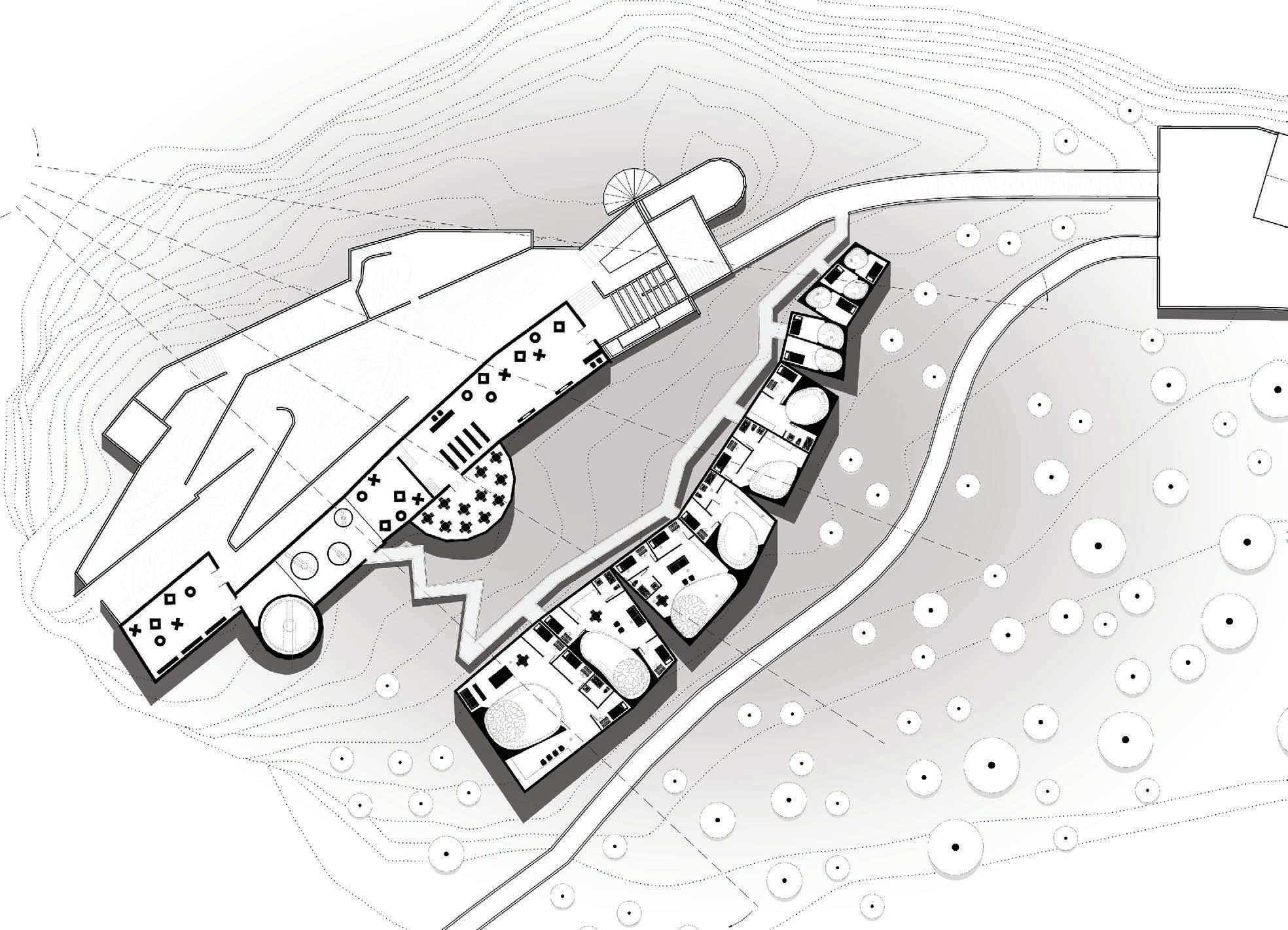
My role in the following project covers schematic design decisions for both site and buildings, client interfacing, and the entirety of the graphic work. Fountain house farm was a three phase project: site planning, cabin and lodge. Paul Coughlin and I, after in-depth site analysis regarding walking distances, flood zones, and user experience, settled on a layout for the farm. We then zoomed in, focusing on the design of the farm’s community lodge and cabins within the existing farm context. We jointly made schematic decisions for a final iteration of the lodge, as well as two options for the cabins. I produced all drawings and graphics.
Fountain House Farm at High Point is a wellness initiative and rehabilitation center in Montague, New Jersey. The goal is to integrate a village of cabins and a lodge building into a working farm and retreat for members. The study looked at the existing buildings on the farm, how they are currently used, how they might be adapted to operate along side new buildings. The plan’s attitude was to be respectful of the existing agricultural architecture and the Chalet, both in terms of proximity and aesthetic.
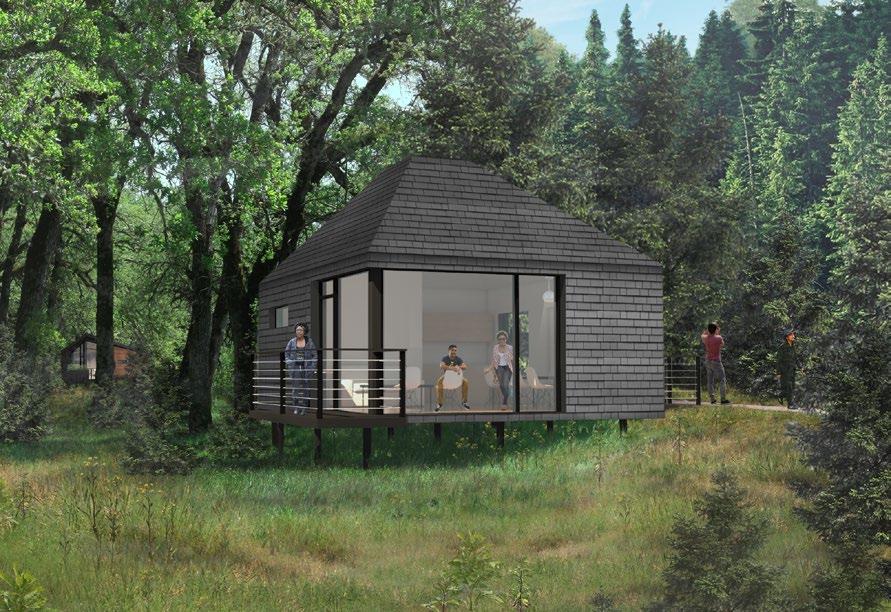
The Village is a collection of micro cabins. The cabins are
meant to provide simple shelter and to allow members to connect with nature. The cabins are conceived to operate on three scales. First, The Singular: Each cabin is a personal incubator towards wellness. This is accomplished by providing a warm, quiet and nurturing space that centers the users both with themselves and with nature.

Second, the collection: The collection of cabins are designed around views, privacy and accessibility, and accounting for both community and separation. Third, the community: The furthest cabin is a 7 minute walk to the existing Farm operations, a chalet and a lodge building. This allows a visitor the choice of separation, but always being a part of the wellness initiative.
The Lodge is the focus of the wellness initiative at High Point Farm. The design established a contemporary dialogue between nature and the existing vernacular agricultural buildings on the farm.The sequence of spaces takes members from the land, through an entry threshold finally into a voluminous gathering hall with views back out to the land and up to the sky. The building is composed of 3 program zones, a small community center, building support space and a large gathering hall.
36
The Lodge will be the heart of the farm for ease of resident and visitor access. Cabins are placed within the woods to enable views of the pond and immersion in nature.


Consideration for distance from the main farm was taken when deciding where to place the program. Users feel independent, but it must be feasible for the less able-bodied.

The form is a simple rectangular mass, modified by two simple operations, shown in diagram 4.
The roof and ceiling are pulled to be tent-like, then the mass is scooped to bring exterior space inside.

 2 _ WALKING DIAGRAM
1 _ SITE DIAGRAM
2 _ WALKING DIAGRAM
1 _ SITE DIAGRAM
PORTFOLIO MICHELLE SCHNEIDER
4 _ FORMAL GESTURES
6 _ LODGE MODEL
3 _ MASSING DIAGRAM
37
5 _ EXTERIOR RENDERING
1 _ CONFERENCE HOUSE PROGRAM


Tables/Chairs Unconcentrated
4-5 staff + 6 ranges, DW, ovens/sink
Tables/Chairs/General
Art/Meditation/Reading/Library
Art/Meditation / Reading/Library
Art/Meditation/Reading/Library
3 fixtures each
HVAC/Sprinkler/Electric
2017 _ PROFESSIONAL FOUNTAIN HOUSE FARM
1 _ LODGE AXON
Room Entrance / Lobby Conference / Dining Kitchen Storage Break Out Room Break Out Room Break Out Room Rest Rooms Mechanical Room Circulation 15% SF 500 3000 400 300 300 300 300 500 400 900 6900 Dims. 20x25 50x60 20x30 20x30 20x15 20x15 20x15 20x25 20x25 83x83 SF PP 15 net 200 gross 20 net 20 net 20 net Persons 125 15 15 15 Notes
38
Scale: Not to scale.
2

Scale: Not to scale.

cabin plan_option 01 scale: 1/4” = 1’-0” interior area: 484 sf exterior dimensions: 22’ x 22’ bathroom 7-6 x 7-8 deck entry walk mech common room 11-6 x 11-6 bedroom 02 10 x 7 bedroom 01 10 x 7 cabin plan_option 03 scale: 1/4” = 1’-0” interior area: 520 sf exterior dimensions: 37’ x 16’ deck mech bathroom 5-7 x 10 entry walk common room 10-6 x 14 bedroom 01 7 x 10 bedroom 02 7 x 10
3 _ CABIN SECTION
1 _ CABIN PLAN - SCHEME ONE
_ CABIN PLAN - SCHEME TWO
PORTFOLIO MICHELLE SCHNEIDER 39
STRAWBERRY MANSION
Professional Project: Coughlin Architecture
Schematic Design
Philadelphia, Pennsylvania
Winter 2017
- My role within this project was aiding in conceptual and schematic decisions, as well as producing all project representational imagery and the decisions for each image. - This project is a ground up residential proposal for the Strawberry Mansion neighborhood of Philadephia, Pennsylvania. Although the project remained in the very early schematic stage, its planning up to this point was very thorough through intensive study of transporation system dynamics around the site. The project was also designed
to ensure that each resident received plenty of natural light, and that its distribution was equitably dispersed. The project is sited directly across from a newly developed park, ensuring that if residents do not get a unit with a roof desk or within the courtyard space, that access to outdoor leisure space would not be missed. The form of the building was purposely playful and use of strawberry red colors complimented the range of colors displayed on the surrounding single family homes within the neighborhood.

1 _ COURTYARD RENDERING
40


 1 _ DIAGRAM, SUN
An analysis used to ensure all residents receive proper daylight.
2 _ DIAGRAM, TRANSPORTATION
1 _ DIAGRAM, SUN
An analysis used to ensure all residents receive proper daylight.
2 _ DIAGRAM, TRANSPORTATION
PORTFOLIO MICHELLE SCHNEIDER
The potential means of transportation and routes within the surrounding block.
3 _ RENDERING
Perspective view of the building in its site within the Strawberry Mansion neighborhood.
4 _ RENDERING
41
A representation of the front facade of the building.
POWER STACK / GRADUATE THESIS
Graduate Thesis Rice University Advisor: Nathan Friedman Pasadena, TX Spring 2023
Power Stack is an urban project that redesigns the value of energy infrastructure. The thesis integrates sustenance, with utility. In the future of energy production, consider not having one that supplies many, but nodes of power storage and supply that serve the local context. The thesis proposes a distributable architecture with an encoded ethical ideology within an urban scheme. A store of value for energy, but contrary to current industrial zones, also serving as a value to its proximity. Gravity-based energy storage, Power Stacks, store surplus energy, which is made available in times of supply fluctuations. Unusable material from previous industrial landscapes are recycled into dense blocks that exist at the top of the Power Stack as potential energy (storage), then slowly descend,
GENERATING
FOCUS: POWER STACK
ARCHITECT AS POLICY MAKER
PASADENA, TEXAS
1149 ELLSWORTH DRIVE PASADENA, TEXAS 77506
spinning a turbine and generating energy in the process. The energy infrastructure is bolstered by floodable landscapes that also mitigate toxicity, remediating the ground upon which the energy infrastructure stands. The design uses three main strategies: water as amenity, the mitigation of toxicity, and energy; it is a coupling of landscape and infrastructure. It is not a final solution, but sets up a hybrid system to reclaim landscapes, a spatial and biological recovery over time. In designing beyond the human, the reclamation of the industrial ground itself will, over time, be acted out through the reinhabitation of native flora and fauna. The grasslands and ponding mimic the Coastal Prairie habitat of the Texas Gulf Coast, 3000 acres artificially regained in which only 1% presently remains.
EQUALITY
JAN
GENERATING EQUALITY
GENERATING EQUALITY
PASADENA, TEXAS
1149 ELLSWORTH DRIVE PASADENA, TEXAS 77506
PASADENA, TEXAS

1149 ELLSWORTH DRIVE PASADENA, TEXAS 77506
ABSTRACT: The obsolescence of oil and gas in Pasadena, Texas provides an opportunity to critically examine how infrastructure might be used as a net-positive urban agitator. How might we use infrastructure as a medium for progress? By considering not only what the infrastructure does as a precise utility, but what it means in urban space.
FOCUS: POWER STACK
JAN 1 3 2023
JAN 1 3 2023
FOCUS: POWER STACK
1- WHAT IS AT STAKE?
ARCHITECT AS POLICY MAKER
ARCHITECT AS POLICY MAKER
ABSTRACT: The obsolescence of oil and gas in Pasadena, Texas provides an opportunity to critically examine how infrastructure might be used as a net-positive urban agitator. How might we use infrastructure as a medium for progress? By considering not only what the infrastructure does as a precise utility, but what it means in urban space.
ABSTRACT: The obsolescence of oil and gas in Pasadena, Texas provides an opportunity to critically examine how infrastructure might be used as a net-positive urban agitator. How might we use infrastructure as a medium for progress? By considering not only what the infrastructure does as a precise utility, but what it means in urban space.
1- WHAT IS AT STAKE?
Texas is an Energy Island, a state whose electrical grid is independent from the rest of the United States; a politically-boasted isolation that allows for a deregulated market. These ‘boasts’ are liabilities, allowing for outdated infrastructure and no national-backup in emergencies. The grid needs to be reliable and equitable. This thesis proposes embedding nodes of energy storage in the grid to ensure backup, a structural redundancy in the present, and a preparation for the energy storage that will be vital for the success of impending renewable energy technologies.
1- WHAT IS AT STAKE?
At stake is Texas’s Energy Giant title, new energy generation methods must compensate for the slow depletion of oil and gas. At stake is an architectural opportunity to rethink the lines drawn between architecture, infrastructure, and landscape, in order to invent progress and advance the ‘green energy’ landscapes we currently envision. At stake are Houstonians, some more than others, who are continually jeopardized by failing infrastructure during city-wide disasters.
Texas is an Energy Island, a state whose electrical grid is independent from the rest of the United States; a politically-boasted isolation that allows for a deregulated market. These ‘boasts’ are liabilities, allowing for outdated infrastructure and no national-backup in emergencies. The grid needs to be reliable and equitable. This thesis proposes embedding nodes of energy storage in the grid to ensure backup, a structural redundancy in the present, and a preparation for the energy storage that will be vital for the success of impending renewable energy technologies.
2- INTRODUCTION ON SITE
Texas is an Energy Island, a state whose electrical grid is independent from the rest of the United States; a politically-boasted isolation that allows for a deregulated market. These ‘boasts’ are liabilities, allowing for outdated infrastructure and no national-backup in emergencies. The grid needs to be reliable and equitable. This thesis proposes embedding nodes of energy storage in the grid to ensure backup, a structural redundancy in the present, and a preparation for the energy storage that will be vital for the success of impending renewable energy technologies.
At stake is Texas’s Energy Giant title, new energy generation methods must compensate for the slow depletion of oil and gas. At stake is an architectural opportunity to rethink the lines drawn between architecture, infrastructure, and landscape, in order to invent
At stake is Texas’s Energy Giant title, new energy generation methods must compensate for the slow depletion of oil and gas. At stake is an architectural opportunity to rethink
1 3
2023
The project site of this unfolding speculation is on 3,000 acres of North-West Pasadena,
largely occupied by oil and gas, adjacent to commercial and residential. The area 42
Texas,

43 PORTFOLIO MICHELLE SCHNEIDER
1 _ HOUSTON CURRENT ENERGY CONDITIONS
1 _ INEVITABLE BIDIRECTIONAL ELECTRICITY GRID

2 _ NORTHWEST PASADENA, TEXAS: SPECULATIVE CONDITIONS
The project site of this unfolding speculation is on 3,000 acres of North-West Pasadena, Texas, largely occupied by oil and gas, adjacent to commercial and residential. The area has some of the least tree coverage in Houston and possesses the slowest population growth of all of Greater Houston. Its residents are victims to many pollutive events with high exposure to cancer-causing agents. This thesis is a speculation on how three layers remediate the area: new energy infrastructure, mitigation of toxicity, and water as an amenity.
44 2023 _ GRADUATE THESIS POWER STACK
Power Stacks and Recyling _ 30 Years

Phytoremedation of Unbuildable _ 5 Years
Canals _ 10 Years
Renewable Energy Landscapes _ 35 Years
Whole Site Remedation _ 75 Years


Floodable Landscape _ 15 Years


Soil Washing _ 5 Years
Capping _ 10 Years
Buffalo Bayou Extension _ 12 Years


1 _ ENERGY INFRASTRUCTURE 2 _ MITIGATING TOXICITY 3 _ WATER AS AMENITY 45 PORTFOLIO MICHELLE SCHNEIDER
1 _ SITE PLAN AND SECTION
The drawing illustrates a moment in time, an estimated 50 years from now, when the total remediation process is well underway. Central notations show the novel elements to the site, but the structures and conditions that are likely to remain on the site.

0’-00” 100’-00” 200’-00” 300’-00” 400’-00” 500’-00” 1000’-00” 1500’-00” GROUNDWATER SUBSOIL HUMUS 0’-00” DRAWING KEY 100’-00” 200’-00” 300’-00” 400’-00” 500’-00” 1000’-00” 1500’-00” DETENTION PONDS COMPONENT: AMENITY DETENTION PONDS AVAILABLE TO STORE INCREASING FLOOD THEREFORE PROTECTING INFRASTRUCTURE, SERVING AS A MANMADE LANDSCAPE THAT GULF COAST PRAIRIE. POWER STACK / COMPONENT: ENERGY INFRASTRUCTURE POTENTIAL ENERGY IS STORED THROUGH THE SLOW DESCENT OF BLOCKS, WHICH SPIN A TURBINE AND GENERATE ENERGY IN TIMES OF LOW GENERATION OF RENEWABLES. CANAL / COMPONENT: WATER AS AMENITY CANALS ARE CONSTRUCTED FOR THE TRANSPORTATION OF INDUSTRIAL LANDSCAPE CAPPING / COMPONENT: TOXICITY MITIGATION TOXIC GROUNDS FROM PREVIOUS INDUSTRY ARE CAPPED, CREATING AN UNDULATING, MANMADE LANDSCAPE THAT PROVIDES AN ELEVATED SPACE FOR SOLAR ARRAYS. LARGE WAREHOUSE SURPLUS STORAGE / EXISTING EXISTING STORAGE FACILITES MAY BE USED TO STORE NECESSARY PARTS FOR NEW ENERGY INFRASTRUCTURE AND LANDSCAPES. 46 2023 _ GRADUATE THESIS POWER STACK


2000’-00” 2500’-00” 3000’-00” 2000’-00” 2500’-00” SOLAR PANEL ARRAY / COMPONENT: ENERGY INFRASTRUCTURE SOLAR PANELS ARE ARRAYED ON TOP OF CAPPED HILLS TO ENSURE INVESTMENT IN RENEWABLE ENERGY IS ABOVE WATER LEVEL AND PROTECTED FROM INCREASING FLOODING. WIND TURBINE / COMPONENT: ENERGY INFRASTRUCTURE WIND TURBINES ARE PLACED ON EXISTING HEAVY DUTY FOUNDATIONS, PREVIOUSLY USED FOR LARGE OIL TANKS. SCRAP RECYCLING / COMPONENT: ENERGY INFRASTRUCTURE RECYCLING CENTERS ARE CONSTRUCTED TO DISPOSE OF TOXIC WASTE FROM OIL AND GAS, WHICH CONSTRUCT DENSE BLOCKS FOR GRAVITY ENERGY STORAGE METHODS. PONDS / WATER AS ARE STORE FLOOD WATERS, PROTECTING NEW AND MANMADE MIMICS THE PRAIRIE. TRANSMISSION LINE RIGHT OF WAY / EXISTING PHYTOREMEDATION THROUGH NATIVE GRASSES AND FLORA IS IMPLEMENTED BELOW TRANSMISSION LINE RIGHT OF WAYS, GROUND THAT REMAINS OPEN DUE TO AN INABILITY TO BUILD STRUCTURES BELOW. METHANE GAS INFRASTRUCTURE / EXISTING METHANE GAS INFRASTRUCTURE IS REUSED TO REPLACE THE PRACTICE OF FLARING, INSTEAD, BEING REUSED AS FUEL FOR THE LOCAL RESIDENTIAL POPULATION. 47 PORTFOLIO MICHELLE SCHNEIDER

48 2023 _ GRADUATE THESIS POWER STACK

49 PORTFOLIO MICHELLE SCHNEIDER

50 2023 _ GRADUATE THESIS POWER STACK
1 _ ROOF PLAN
The roof shows the new bulkhead, the coordination of required solar panels, fire access, a new roof deck for tenants, and the modern and newly occupiable roof from what once was a non-accessible asphalt roof space.

51 PORTFOLIO MICHELLE SCHNEIDER
1 _ ROOF PLAN
The roof shows the new bulkhead, the coordination of required solar panels, fire access, a new roof deck for tenants, and the modern and newly occupiable roof from what once was a non-accessible asphalt roof space.
This thesis turns on its head the practice of divorcing industrial production from the zone in which it serves - it collapses the site of production into the store of value - through the architectural focal point, the Power Stack - and makes one’s proximity to that store a built in side-constraint against the capital incentives of the status quo that seek to imperialize and export them away. The design remediates the material site, but also remediates the narratives of living within the industrial zone itself for the living and for the landscape, and in doing so, encodes an ethics for dignified, self-sufficient, urban life - a heritable quality it can then pass to future projects, attitudes, and communities.

52 2011 _ 2023 FINAL PAGE
1 _ IMAGE FROM GRADUATE THESIS PRESENTATION
53
PORTFOLIO MICHELLE SCHNEIDER
THANK YOU FOR YOUR CONSIDERATION.
