
2 minute read
EMC Measures for Grounding Systems

EMC Measures for Grounding Systems
EMC functions of the grounding system The grounding system has the following tasks with regard to EMC: Interference current dissipation Prevent couplings Maintaining shielding at specific potentials The grounding system must fulfill these requirements without interfereing with the device and wiring. NOTE: Green-yellow equipment grounding conductors are not usually suitable for these tasks. Grounding conductors can only dissipate low-frequency signals (50 ...60 Hz), and do not guarantee equipotential bonding for high-frequency signals as their impedance is too high.
Advertisement
Effect of grounding The galvanic coupling is affected by the ground connection. Disturbances can spread via the grounding system across the entire plant if the grounding system is poorly configured or bad connections are made.
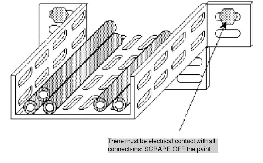
EMC measures for grounding systems The following EMC arrangements are available for grounding systems: Optimal selection and combination of grounding systems (point-to-point or meshed) if necessary Meshed grounding: sufficiently small surface area of the loop between exposed conductive parts Sufficient cross-section of the earth conductors low-resistance and low-inductance lines and therefore an effective equipotential bonding for low and high frequency signals Good chassis connection to decrease the contact resistance
Types of grounding systems Two types of grounding systems are used: S Type: Point-to-point M Type: Grid-type Large plants use both grounding types in combination as they have varying effectiveness depending on the application. The advantages and disadvantages of each system are described below.
S type grounding system With point-to-point grounding of reference conductors, every reference conductor to be grounded in a circuit is only connected once to ground at a central point. Point-to-point grounding system
Advantages and disadvantages of point-to-point grounding Advantages of point-to-point grounding for reference conductors Reference conductors cannot be coupled and disturbance caused by induced voltages is not possible at low-frequencies At low-frequencies, no or only slightly different potential differences between ground and reference conductor can occur.
Disadvantages of point-to-point grounding for reference conductors A point-to-point grounding system can only be achieved at high cost due to additional isolation. High-frequency coupling are possible. Different conventional reference potentials can occur at high frequencies. Isolated arrangement of device chassis is required against the reference conductor.
Grounding system type M With grid type grounding, the reference conductors are connected multiple times to the chassis connection. This creates a meshed system. The connections are arranged between the devices ground, cable runs, existing or under construction metal structures etc. Shielding, filtering devices return conductors, etc. are directly connected to this cable.
Grid-type grounding system
Advantages and disadvantages of meshed grounding Advantages of meshed grounding for reference conductors Lower potential difference for high-frequency disturbance within the grounding system No isolated arrangement of device chassis is required against the reference conductor. Disadvantages of meshed grounding for reference conductors Galvanic couplings between different circuits via common impedance and currents is possible as a consequence of the induced voltage in the conductor loop.


