
2 minute read
Connecting TSX SUP A05 supply modules

Connecting TSX SUP A05 supply modules
Illustration Connection diagram:
Advertisement
(1) Connection if supply is from 100...120V alternating current network. (2) External protection fuse on phase (Fu): 6.3A time delay 250 V. (3) Shielded AS-i cable screen in case of disrupted surroundings.
Connection overview The TSXSUPA05 supply module is designed to supply the AS-i bus, including the slaves which are connected to it (30V/5A output). It also has an auxiliary supply (24VDC/7A) for sensors/actuators which consume large amounts of current. For this, a black AS-i ribbon cable is used.
Principle diagram:
Rules of connection
Primary: observe the rules concerning phase and neutral when wiring. an operating voltage ≥ 600VAC with a cross-section of 1.5mm2 (14AWG) or 2.5mm2 (12AWG) for connection to the mains,
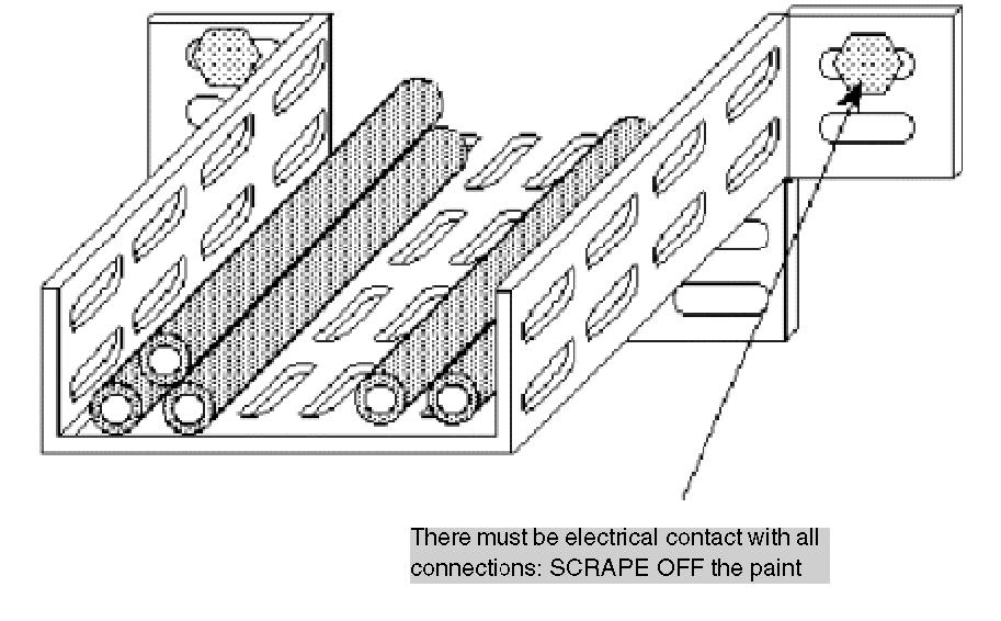
The "AC power supply network" and "24V and 30VDC output" AS-i terminals are protected by a flap allowing access to the wiring terminals. The wires come vertically out of the power supply at its base. These wires can be kept in place with a cable-clip.

DANGER
RISK OF ELECTRIC SHOCK
Connect the module grounding terminal to the protective ground, using a green/yellow wire." Failure to follow these instructions will result in death or serious injury.
Secondary: to comply with isolation requirements (EN60950) for a 24VSELV isolated voltage, the following wiring is used: an operating voltage ≥ 300VAC with a cross-section of 2.5mm2 (12AWG) for the 24V outputs and the ground, connect the two 24V terminals in parallel, or distribute the load over the two 24V outputs when the total current to be provided is greater than 5A. Using a shielded cable for the AS-i bus is only necessary if the installation is overly disrupted in terms of EMC (Electro Magnetic Compatibility). Given the large current that this supply module provides, its position on the bus is very important. If the supply module is placed at one of the ends of the bus, it will provide a nominal current (e.g. 5A) for the whole bus. The voltage drop at the end of the bus is therefore proportional to the 5A. If it is positioned in the middle of the bus, the voltage drop at the ends is proportional to only 2.5A, assuming that the consumption for both sections of the bus is the same.
If there is no slave which consumes large amounts of power, it would be better to place the supply module in the middle of the installation. Conversely, if the installation has one or several large power consumers, it would be wise to place the supply module close to them. NOTE: Where there are large power consumer actuators (contactor, solenoid coils etc.) the TSXSUPA05 supply module can provide the auxiliary 24VDC, insulated from the AS-i line.


