
1 minute read
Wiring precautions

Wiring precautions
General
Advertisement
The I0, I1 and I3 inputs are rapid inputs, which should be connected to the sensor using either a twisted wire if it is a dry contact, or using shielded cables if it is a 2 or 3-wire proximity sensor. The module integrates basic protection against short circuits or voltage inversions. However, the module cannot remain operational for long with an error. You must therefore ensure that the fuses in series with the supply carry out their protective function. These are 1A maximum non-delay fuses, the supply energy must be sufficient to ensure their fusion.
Important Note: Wiring of Q0 Static Outputs The actuator connected to the Q0 output has its shared point at 0 V of the supply. If for any reason (poor contact or accidental unplugging) there is a 0 V outage of the output amplifier supply, when the 0 V of the actuators remains connected to the 0 V supply, there may be enough mA output current from the amplifier to keep low-power actuators locked. Illustration:
Connection via TELEFAST This kind of connection provides the most guarantees, on condition that the shared actuators are connected to the bar for shared points 200 to 215 (jumper wire in position 1-2). In this case there can be no outage of the shared module without an outage of the shared actuators.
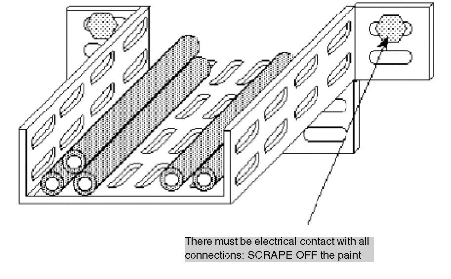
Connection Using Strips This kind of connection must be carried out with the highest care and attention. It is recommended that you take special care in wiring this cable, for example using cable markers on screw terminals. It may be necessary to double the connections in order to ensure permanent contacts. When the actuator supply is a long distance away from the modules and close to the shared actuators, there may be an accidental break in the link between the latter and the 0 V or modules terminal Illustration:
If there is a break of the supply section between A and B, there is a risk that the RL actuators may not remain operational. You must, if possible, double connections of 0 V supply to the modules. Using TSX CDP 301/501 strips:


