22 minute read
A guide to hazardous location equipment marking


Despite their common appearance on almost everything purchased for industrial, commercial or personal use, equipment markings are one of the least understood and most error filled aspects when going through the compliance and certification process.
The markings and nameplate of a particular device or piece of equipment are meant to be a short description of the equipment enabling the end user to procure the correct equipment for the application and install it correctly. However, when markings are incorrect or confusing it can lead to wasted time being spent interpreting and clarifying what the original manufacturer intended to tell the end user about the equipment, including where and how it may be installed. Unclear markings may also lead to the incorrect piece of equipment being purchased for the application.
Advertisement
The level of markings is largely based on the standard being applied during the certification of the equipment being manufactured. The importance of markings is often downplayed and is quite often an after-thought during the certification process. In reality, they should be one of the first things considered when developing a product as they can often lead to differing evaluation criteria and design considerations for the equipment.
If equipment is manufactured with confusing or incorrect markings, it may lead to the manufacturer having a product which may not meet the criteria of what they originally intended to produce and may result in missing the target client or consumers of the equipment. This article seeks to inform equipment manufacturers and end users about what the various markings typically placed on equipment mean and why certification bodies require certain markings to be shown. We will focus on hazardous locations markings for International markets (via the IECEx), Europe (ATEX) and North America and will include explanations on what and why certain markings are required.
Why is equipment marked?
Equipment is marked to identify it and answer the following questions: • Who made it? • What is it? • Where can it be installed? • How should it be installed? • What restrictions or safety concerns are related to the equipment?
Problems with incorrect or incomplete markings
Incomplete or inaccurate markings may not detail the complete information, leading to incorrect application or installation and installation preparation. For example, incorrect ratings of information can lead to the incorrect specification of cable sizes.
The equipment may miss the target audience – those searching for specific criteria may dismiss the manufacturer’s equipment because it is not marked to meet their specifications, or may be marked to meet, but actually will not.
How are equipment markings specified?
From a compliance and certification perspective, the preference is that markings are at the manufacturer’s request. • The manufacturer originally specifies markings to meet what they target the equipment to be and the specific needs they want to fulfil • The product standards that are applicable to the equipment contain minimum marking requirements • These standards include the basic marking requirements as well as optional warnings and information
General marking requirements
The following markings are typically required to be placed on all equipment regardless of the standards being used to evaluate the equipment.
Manufacturer name:
• Who made the equipment and is responsible for the placing of the equipment on the market? • Who does the end user go to when they are looking for support with the equipment?
Model Number:
• What is the equipment? • This allows the manufacturer and the end user to determine that they are talking about the correct piece of equipment when building it, ordering it or providing support
Serial Number or date code:
• When was the equipment made/ manufactured? • There may be known problems with equipment manufactured on a specifi c date or as part of a specifi c batch. • Product recalls may be specifi c to only certain pieces, not all of the equipment manufactured
Electrical ratings and specifi cations:
• How much power is needed for electrical equipment (KW/KVA)? • What type of Power Supply is required (3-Phase AC, Single Phase AC, etc.)? • What overcurrent protection requirements are there? • What size and type fuses are installed in the equipment? • What size of cable is required for the application? • What range of external infl uences is the equipment likely to encounter?
Ambient temperature range:
• Is the equipment able to be run properly in the environment where it is to be installed? • May not always seem important, but have you ever tried to install a compact fl orescent light bulb outdoors in
Canada in the winter
Enclosure environmental rating:
Commonly referred to as External Infl uences within standards and codes of practice. • Is equipment suitable for use indoors or outdoors? • Is the equipment able to withstand harsh environments, such as where the equipment could be subjected to impact, vibration, humidity, etc.
Warnings:
Is there anything in particular that the end user needs to be made aware of from a safety perspective. • Multiple power sources • High internal voltages • Dangers when opening enclosures
Certifi cation information:
• Specifi c safety mark or certifi cate number • Who carried out the third-party evaluation on the equipment (While this may not appear important, it informs the user and the local authorities who
holds the evidence that the equipment was evaluated to a specifi c standard and that the equipment meets the defi ned minimum safety requirements of the standard used) • Whether there are specifi c conditions of use (indicated by “X” in the certifi cate number for ATEX and IECEx certifi cations) • Whether a piece of equipment requires additional certifi cation before use (indicated by “U” in the certifi cate number for Ex Components under
ATEX and IECEx Certifi cations)
Hazardous locations specifi c markings
Hazardous area equipment has specifi c markings required by the applied standards/directive to allow the installers and end users to ensure they are installed suitably for the applicable area. The intent of the marking is to inform the reader about the ratings of the equipment and the types of hazardous area it has been investigated and tested for use in.
• Informs the end user what sort of area the equipment can be installed • Applicable to all equipment being installed into a potentially explosive atmosphere • These markings can allow or disallow certain equipment from being installed into the intended area
Temperature rating
• How hot does the equipment get on the surfaces exposed to the explosive atmosphere • Combined with the area classification information, these markings tell the user how hot the equipment can get under normal or abnormal operating conditions • This can qualify or disqualify certain equipment from being installed depending on the materials present in the area and the auto ignition temperature of those materials.
ATEX specific markings (see ‘Typical ATEX and IECEX Marking’ graph on previous page)
CE mark: • Indicates the manufacturer declares the equipment meets the applicable
Directives • For ATEX certified equipment, the number following the CE mark is the number for the Notified Body which performs the surveillance activity for the
ATEX Directive. • The number after the CE mark indicates that a Notified Body is responsible for surveillance of manufacturing. • When the CE mark does not have a
Notified Body number after it, this means that the manufacturer is responsible for the design and manufacture of the equipment and that there is no
Ex specific Notified Body audit of manufacturing in place for this product
Epsilon Ex Mark: • Indicates that the equipment meets the requirements of the ATEX directive
Equipment group: • Indicates what sort of area the equipment may be installed • I – Mines susceptible to firedamp • II – Gas or dust atmospheres
Equipment category: • 1 – Suitable for Zone 0, 1, 2, 20,21 or 22 • 2 – Suitable for Zone 1, 2, 21 or 22 • 3 – Suitable for Zone 2 or 22 • M1 - Very high level of protection for mines • M2 - High level of protection for mines
Environment: • G – Gas • D – Dust • * Not used for M1 or M2
ATEX and IECEx specific markings
Ex: • Indicates the equipment is for use in an explosive atmosphere
db: • Protection Method - There are ten recognised electrical and four mechanical concepts of protection.
These are detailed in the European & IEC 60079 and 80079 series of
Standards • There are four basic methods used in order to avoid uncontrolled ignition: – Exclusion of the flammable substance. – Prevention of component sparks or hot surfaces. – Contain the explosion and extinguish the flame. – Energy limitation
Atmosphere Groups: Indicates the specific gas or dust environment the equipment has been evaluated for • I - mining • IIA - atmospheres containing propane or gases of an equivalent hazard • IIB - atmospheres containing ethylene or gases of an equivalent hazard • IIB+H2 - atmospheres containing
Ethylene and hydrogen • IIC - atmospheres containing hydrogen or gases of an equivalent hazard (acetylene) • IIIA - atmospheres containing flyings (fibres) • IIIB - atmospheres containing combustible non-conductive dusts. • IIIC - atmospheres containing combustible conductive dusts
Temperature Codes: • IEC and North American temperature codes use the same standard values for T1, T2, T3, T4, T5 and T6 to indicate their corresponding maximum temperatures of equipment. • North American Standard goes further and subdivides T2, T3 and T4 into subdivisions. • IEC utilises 6 temperature divisions, whereas the North American standard utilises a total of 14 divisions. • For Group III equipment, the actual temperature is marked, for example
T135°C
Max. Surface Temperature
450°C 300°C 200°C 135°C 100°C 85°C
ATEX / IEC*
T1 T2 T3 T4 T5 T6
Note: For Group I applications (ATEX and IECEx only), electrical apparatus has fixed temperature limits of 150°C (where layers of coal dust can form) and 450°C (where coal dust is not expected to form a layer.)
For Group II applications, the T Class may be replaced by a temperature in degrees Celsius, and if a specific gas is marked, rather than sub-group, a temperature class or maximum surface temperature need not be marked.
Equipment protection level (EPL): Indicates which locations the equipment is suitable for installation within; • Ga – Zone 0, 1 and 2 • Gb – Zone 1 and 2 • Gc – Zone 2 • Da – Zone 20, 21 and 22 • Db – Zone 21 and 22 • Dc – Zone 22 • Ma – Very high level of protection for mines • Mb – High level of protection for mines
Note: The correlation between the EPL and Zone is only a guide
Scheme
Class I: Hazard Classifi cation • Class I - Combustible Gases • Class II - Combustible Dusts • Class III - Fibers and Flyings
Division 1: Area Classifi cation – How often the explosive atmosphere is present • Division 1 – Atmosphere is always present • Division 2 – Atmosphere is only present in abnormal conditions
Groups A, B, C, D: Atmosphere (Gas or Dust) Group • A - atmospheres containing acetylene or gases of an equivalent hazard • B - atmospheres containing hydrogen or gases of an equivalent hazard • C - atmospheres containing ethylene or gases of an equivalent hazard • D - atmospheres containing propane or gases of an equivalent hazard • E - atmospheres containing combustible metal dusts • F - atmospheres containing combustible carbonaceous dusts. • G - atmospheres containing combustible dusts not in Group E or F
Temperature Codes (see following table): • IEC and North American temperature codes use the same standard values for T1, T2, T3, T4, T5 and
T6 to indicate their corresponding maximum temperatures of equipment. • North American Standard goes further and subdivides T2, T3 and T4 into subdivisions. • IEC utilises 6 temperature divisions, whereas the North American standard utilises a total of 14 divisions.
Max. Surface Temperature NEC* 500 / CEC* NEC* 505
450°C (842°F) T1 T1 300°C (572°F) T2 280°C (536°F) T2A T2 260°C (500°F) T2B 230°C (446°F) T2C 215°C (419°F) T2D 200°C (392°F) T3 180°C (356°F) T3A T3 165°C (329°F) T3B 160°C (320°F) T3C 135°C (275°F) T4 T4 120°C (248°F) T4A 100°C (212°F) T5 T5 85°C (185°F) T6 T6
North American specifi c markings - Zone Scheme
In Canada, markings match the IECEx markings. In the USA, the following items are added: • Hazard Class – Matching Division
Scheme • Area Classifi cation • Similar to the Division Scheme, indicating the Zone the equipment is able to be
installed within; • Zone 0/20 – Gas or dust is always present • Zone 1/21 – Gas or dust is normally present • Zone 2/22 – Gas or dust is abnormally present
The remaining string matches the IECEx specifi c markings (see previous sections).
Examples of equipment markings
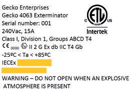
This device is manufactured by Gecko Enterprises, is a Gecko Exterminator and is powered by 240Vac supply, rated at 15A. It is IECEx, ATEX and North American certifi ed and can be used in a Class I, Division 1, Groups ABCD or Zone 1 hazardous area.
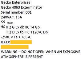
The above example is the same device as the previous device, however this one has multiple protection methods. It can be installed in either a gas or a dust explosive atmosphere.
Conclusion
Although many manufacturers face a plethora of complications and challenges when selecting the markings for their electrical products, it’s clear to see the importance of selecting the correct global markings at the initial design phase. This is crucial to ensuring that your end customers understand the product they’re purchasing, and also so that it bears the correct markings to be sold in the relevant countries you intend to sell your hazardous location electrical product into.
Hazardous area markings can be complicated, but they are vital in ensuring the safety of all personnel exposed to potentially explosive atmospheres. With training and understanding, even the most complicated of markings can become simple to understand.
About the author
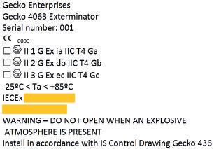
Multiple optional protection method device:
The above example is the same device as previous however this one has multiple protection methods.
It is up to the end user and installer to choose and indicate which installation method they wish to use for the installation by marking the box as indicated. Wesley Van Hill is the Global Technical Manager for the Intertek Hazardous Locations team responsible for multiple locations worldwide. His responsibilities include ATEX and IECEx technical qualifi cations and consistent technical decision making within all Intertek facilities performing Hazardous Locations related activities. He has been involved in the evaluation of hazardous locations equipment for almost 15 years and has been a part of multiple technical committees and panels. Prior to joining Intertek, he gained manufacturing and testing experience with a large multinational manufacturer.
External corrosion – the slow, silent assassin
The anti-corrosion professional organisation, NACE International, estimated that external corrosion cost US process industries in excess of $1.7 billion in 2013. It also calculated that North American organisations were spending a total of $260 million annually on coatings to prevent external corrosion. As a clear and present threat to most equipment in every process facility, external corrosion warrants closer analysis and prediction.
For internal corrosion, industry guidance and risk-based inspection standards use a combination of material type, environment (e.g. fl uid, pressure, temperature) and corrosion protection measures to help asset integrity specialists decide which threats are credible. However, the technical support to competently analyse and predict external corrosion is rare.
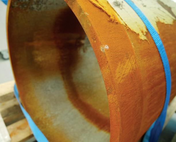
Internal corrosion is seen as easier to quantify and predict but external issues and threats are just as common to almost all process equipment and pipelines. While the development of general external corrosion can often be slow, it can do much damage over a plant or pipeline’s lifetime (Figure 1).
It can be aggressive, especially along coastlines in hot climates when salt fogs wet steel surfaces in the morning. Water evaporation during the day drives up the salt concentration to cause high rates of corrosion and coating damage. Likewise,
high external concentrations of sulphur oxide pollution greatly accelerate external corrosion by acidifying water and destabilising rust layers.
External corrosion can also be unexpectedly high, even in inland areas. After ‘the Great Storm’ of 1987 in the UK, a study in central London found that, due to salt transport from the sea into the city, the external corrosion rate was equivalent to that next of coastal locations.
Combating CUI
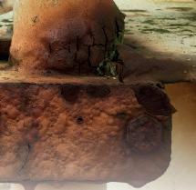
Well-established risk-based inspection codes such as API 581 address general external corrosion attacks and corrosion under insulation (CUI). CUI is the external corrosion of pipework and vessels that occurs underneath externally clad/jacketed insulation due to water penetration. It tends to remain undetected as corroded areas are difficult to identify and conventional inspection methods are impeded by the insulation. Identified as a major threat to the integrity of oil and gas and petrochemical facilities worldwide, CUI damage can take the form of localized external corrosion in carbon and low-alloy steels, external stress corrosion cracking (ESCC) or pitting in austenitic and duplex stainless steel (Figure 2).
Insulation related corrosion is a major problem and has been responsible for a significant number of incidents and lost production time and is thought to account for 40-60% of pipework maintenance costs. Detailed guidance on CUI management is available in documents from the European Federation for Corrosion (EFC 55) and NACE International (RP0198).
The American Petroleum Institute (API) 581 standard also considers factors such as climate, condensation and how close equipment is to sources of potentially corrosive water mists, such as cooling towers. However, risk-based inspection schemes rarely include enough detail when specifying corrosion loops to pinpoint the areas of highest external corrosion risk. Current discrepancies also include the use of insufficient inspection methods, which can lead to undetected defects and the ultimate neglect of the whole asset. Others currently manage CUI risk by blindly replacing and renewing all insulation in a systematic manner, with limited upfront assessment of the scope required.
DNV GL has launched a new recommended practice (RP) designed to address the major safety threat and multi-billion-dollar cost posed by CUI. DNVGL-RP-G109 was developed in collaboration with major operators and the supply chain to deliver a practical and cost-effective recipe for managing its occurrence (Figure 3).
Figure 2 – CUI is a major threat to the integrity of oil and gas and petrochemical facilities worldwide
Figure 3 – DNVGL-RP-G109 was developed in collaboration with major operators and the supply chain
The RP is intended for use in the risk assessment of insulated static mechanical pressure systems, considering failures caused by loss of pressure envelope containment due to external CUI. The methodology is designed to be applied to process systems that operate at temperatures below 200°C and largely concentrates on the CUI of metallic materials, particularly carbon steel. Within the RP, DNV GL presents a systematic approach to CUI risk management, which includes the assessment, mitigation and updating of risk as well as continuous improvement. The approach is appropriate for both short and long-term time frames, taking into consideration related factors such as roles and responsibilities, reporting requirements and change management. Historic decisions made on individual assets also need to be aligned such as the material selection, coating condition and maintenance strategies.
Knowing the corrosive enemy inside and out
DNV GL’s failure analysis laboratory in Loughborough, UK has investigated major issues of external corrosion on flange faces, bolting and piping across various industries (Figure 4).
This has included instances where bolts have fractured due to loss of cross section and when flange corrosion was so severe that a fitness for service assessment was required. The key factors that were found to increase the risk of external corrosion were: • Facility age – assets more than 20 years old had more extensive corrosion • Coating inspection and maintenance – facilities with little or no coating management had severe external corrosion • Water accumulation – areas where water can accumulate suffered enhanced attack.
This included horizontally aligned flanges and items exposed to water run-off. In one case, a flat beam above a flange caused a mini waterfall whenever it rained and severe external attack occurred.
Figure 4 – DNV GL laboratory in Loughborough
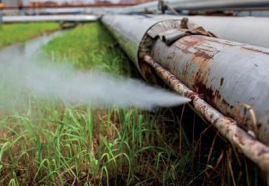
Corrosion under pipe supports (CUPS) for instance, is a particularly insidious form of corrosion that occurs at the pipe support to pipe interface (Figure 5).
This can rapidly lead to serious piping damage, potentially resulting in pipe failure. Design features, such as using rubber spacers or poor draining supports, which can trap water and damage coatings, can accelerate it.
Improving inspection and maintenance
Asset integrity specialists continuously enhance their abilities to recognise what corrodes process facilities, how, and the rate of corrosion. It allows them to better optimise inspection and run mitigation programmes to maintain safe operations. Improving the scheduling of inspection and maintenance procedures helps to ensure that resources that could be used elsewhere in the business are not needlessly diverted to these activities.
This means finding new or improved ways to identify, measure and predict external degradation modes for each type of equipment. Factors such as climate, location, pollution levels, aerosol, salt transport measurements, airborne particulates, condensation, rain sheltering, and industry guidance are used together to assess the magnitude of the external corrosion threat. External corrosion appears simple at first glance, but its prediction can be just as complex as that for internal corrosion mechanisms.
The increasing volume of digital data and sophisticated analytical software available in process industries assists asset integrity specialists in this quest.
The trend for using 3D models for process assets facilitates external corrosion risk assessment of piping circuits as they provide improved details of the pipe configuration compared to paper drawings (Figure 6). For existing assets, laser scanning can be used to make up-todate models of the pipe configurations. Eventually the 3D model, inspection data and real-time climate/environmental data will allow the creation of a digital twin of the asset. This will involve using analytics to predict external corrosion, plan inspections and direct coating maintenance activities to the areas at highest external corrosion risk.
For ease of implementation, an interactive digital tool, which combines the new CUI RP with live asset data, has been developed by the technical adviser to the oil and gas industry. DNV GL’s cloud-based ‘CUI Manager’ application will enable users to assess CUI risk and evaluate the risk impact of different mitigation measure, such as radiographic testing inspection, general visual inspection or close visual inspection after removal of insulation.
Figure 5 – Corrosion under pipe support
The oil and gas industry, and others, coat and paint vessels and pipework as their main way to mitigate external corrosion attack. This can work well if the coating is carefully selected and qualified for site conditions.
However, there have been failures (Figure 7). For example, when a coating against atmospheric corrosion is used on cool pipework, this can potentially result in heavy condensation occurring from a humid atmosphere. In this case, an immersion-grade coating would be required.
DNV GL’s coating test facilities qualify coating systems for many operators including equipment to simulate conditions worldwide, as well as examining the effects of pollutants.
Coating laboratories are equipped with advanced environmental simulation chambers that allow coatings to be exposed to humidity and temperature cycling as well as ultra-violet light and simulation of pollutant gases. This enables experts to test coating performance in environments ranging from rainforests to
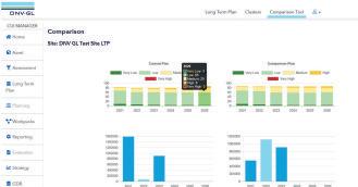
Figure 6 – DNV GL’s cloud-based ‘CUI Manager’ application will enable users to assess CUI risk
About the author
deserts. One recent project examined the performance of products applied as a single coat compared to the operators specifi ed three-coat systems. It was found that a single-coat system would greatly reduce the time needed for maintenance painting and for many environments, provide adequate protection.
Standards and guidelines
Coating systems need regular inspection to evaluate their condition and detect any evidence of the early stages of corrosion. Many operators have internal standards for assessing the severity of corrosion and coating degradation. International standards such as ISO 4628, ASTM D5065 and D610 can also be applied.
All these standards involve comparing coated surfaces to a library of pictures showing coatings and steel substrates with varying levels of damage to assess the degrees of coating degradation and substrate surface rusting. They do not however, address the depth of attack under rust layers. The chief issue with this approach is the subjective nature of the judgements, which often depends on the experience of the inspection personnel. To ensure a consistent approach, trained assessors are used in Loughborough’s materials laboratory to conduct site surveys for external corrosion, CUI and CUPS. A recent survey of a process facility looked at more than 2,000 locations and found 2% required urgent attention and 10% needed more frequent inspection.
Improving external corrosion management
The oil and gas and process industries continue to improve the management of internal corrosion by investing heavily to develop continuous corrosion monitoring, predictive tools and data management software.
As industry adopts these and similar tools more widely, the control of external corrosion attack will be much improved and the risks better controlled. Dr. Tim Illson is Principal Specialist with DNV GL – Oil & Gas and has worked in industrial corrosion control for more than 30 years and is presently involved in consultancy for a wide range of oil and gas, transport, processing and production activities. Consultancy roles performed include corrosion management planning, corrosion engineering, production chemistry and fl ow assurance. Specifi c areas of technical expertise include hydrogen compatibility, selection and application of corrosion monitoring techniques together with their interaction with inspection, materials selection for oil and gas processing plants, and risk-based life cycle costing and economic analysis.