Building Information Modeling_
 by mohamed elmubarak
2 Contents curriculum vitae 3 modeling 4 floor plans 10 elevations 14 sections 18 detailing 22 families 24 scheduling 26
I am mid-level architect with comprehensive experience in preparing architectural designs for the full completion. Skilled in applying creativity to designs highly appealing and functional designs that engage emotion. Proven the ability to successfully deliver agrees upon superior quality solutions. I think the absolute creation is the architecture of nature, and the combination between science and art which define architecture. Because of that I believe creating an adaptation between nature and human through architecture is essential.
education
2021 - present masters of science in building architecture, polytechnic university of milan 2013 - 2018 bachelor of science in architecure and planning, sudan university of science and technology.
experience
2018 - 2020 junior architect at iskan architects. nov. 2018 - dec. 2018 intern at degraphy studios.
2018 - 2019 teaching assisstant at SUST.
2017 - 2018 CAD instructor at new horizon training center.
contact
email | m.elmubarak.wail@gmail.com
phone | +(39) 3516760603
linkedin profile
arabic C2
english C1
italian a1
languages skills
professional technical
architectural design
architectural drafting
architectural presentation
3d modeling scheduling
rendering
bim
autodesk autocad
autodesk revit
autodesk 3dsmax
sketchup
adobe photoshop
adobe indesign
lumion
enscape synchro 4d
dalux
velux daylight visualizer
microsoft suite
tekla structures
3 curriculum vitae
the modeling process done through-out the architectural design helped achieving segnificant level of details using different tools from conceptual and detailed modeling in sketchup and 3ds max.
yet revit played a major role on delivering a high level of detials and flexability when shifting from different drawing views from plans and sections to elevations. After settling on the main idea, the bulk the production starts on revit (all drawings).
4 modeling
5
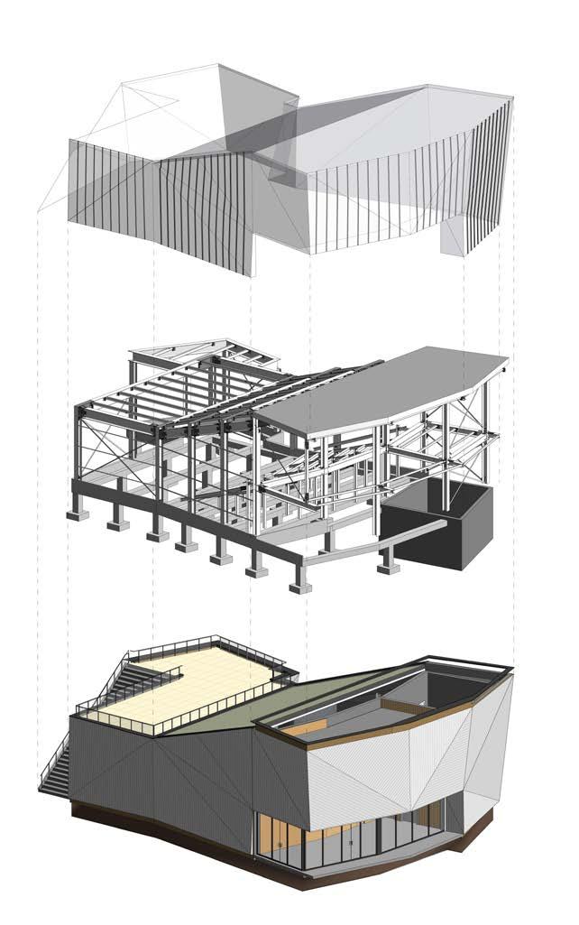
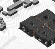
1. in the design of this auditorium the conceptual idea was done in sketchup , and then shifted to revit through mass modling preparing the outer shell of the building dividing it to floors and then modeling the structural parts with full steel detailed joints and a clad of panels carried by customized mechanical system of purlins.
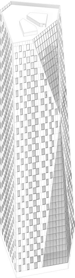
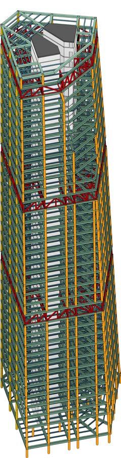
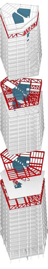
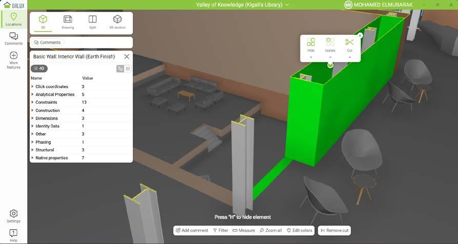
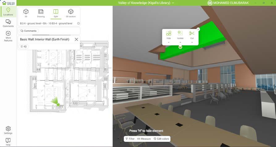
2. malmo lighthouse tower was an expentional challenge considering the size and the amount of geometry involved from structural elements and archtiectural components. using revit and various softwares like tekla the exploration of the structural options was possible, including the coordination using dalux .
6
modeling
1
7 2
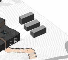
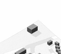
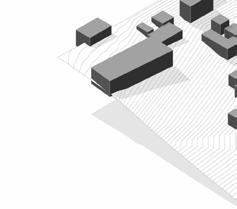
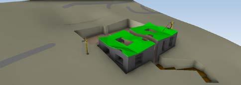
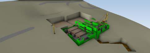
3. valley library was a test on understaing the works of topography and how to model a building on it through autocad exporting the contour lines done in sketchup location import, to revit toposurface tools of site.


8
modeling
4. considering the difficulty sometimes with the time limit some of the families were created after being modeled and imported in sketchup to revit .
9
floor plans
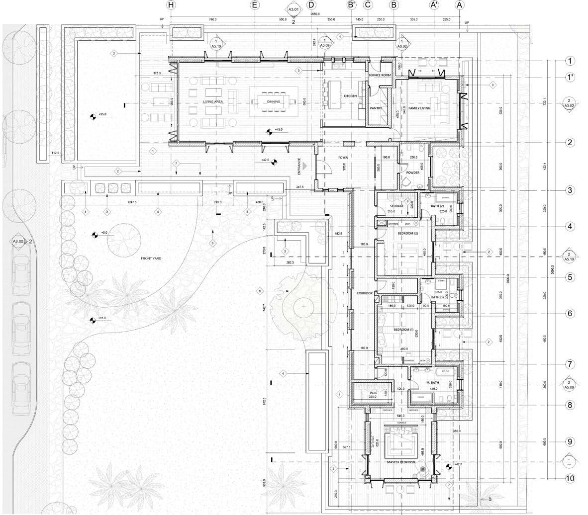
the section of the floor plans describes various sizes of buildings and different ways of annotating the inforamtion related to these projects with the respected to the standards. with revit creating detail adaptive families helped in the production process of the construction drawing.
10 DN 1350.00 30.00 15.00 -10.00 930.00 1350.00 930.00 -330.00 15.00 510.00 510.00 0.00 510.00 30.00 15.00 1:0 1:0 1:0 1:0 1:0 1:0 1:0 1:0 2600.0 1730.0 481.0 311.8 1255.0 725.0 1158.5 420.0 365.1 725.0 535.8 422.0 595.9 655.0 76.3 191.3 542.8 153.5 378.2 153.5 542.7 179.8 99.9 164.9 525.3 85.2 318.2 262.9 251.3 126.9 4 5 2 3 6 2 3 4 4 7 3 1350.00 1 1 2 3
11 UP UP UP A3.01 1 A3.02 1 A3.03 1 A3.00 1 1 A3.04 1 A3.05 A6.01 2 A6.00 1 H G D B F E C A I 1 2 3 4 5 6 7 8 9 10 11 13 m² DIRTY KITCHEN 13 m² DINNING 20 m² KITCHEN 66 m² LIVING AREA 28 m² MAJLIS 4 m² DRIVER'S ROOM 2 m² BATH 3 m² TOILET 3 m² WASH AREA 3 m² TOILET 6 m² FOYER 3 m² WASH AREA 6 m² STORAGE 30 m² DINNING 1 A3.06 F.F.L +0.00 F.F.L +30.00 F.F.L +0.00 F.F.L +0.00 F.F.L +30.00 400.0 500.0 160.0 170.0 160.0 180.0 180.0 280.0 110.0 200.0 100.0 210.0 180.0 200.0 200.0 210.0 OVERALL DIM. 1300.0 200.0 190.0 200.0 250.0 200.0 595.0 430.0 365.0 160.0 410.0 OVERALL DIM. 3000.0 360.0 580.0 560.0 180.0 180.0 310.0 180.0 90.0 180.0 170.0 570.0 380.0 380.0 160.0 300.0 580.0 760.0 LIFT 760.0 A5.00 1 A5.01 5 UP A3.01 1 A3.02 1 A3.03 1 A3.00 1 1 A3.04 1 A3.05 A6.00 2 H G D B F E C A I 1 2 3 4 5 6 7 8 9 10 11 9 m² OFFICE 3 m² BATH 15 m² BEDROOM 1 15 m² BEDROOM 2 4 m² BATH 15 m² BEDROOM 3 32 m² MASTER BEDROOM 9 m² M.BATH 12 m² DRESSING 4 m² BATH 8 m² KID'S ROOM 15 m² LIVING AREA 3 m² BALCONY 1 A3.06 360.0 160.0 380.0 230.0 110.0 300.0 280.0 540.0 400.0 140.0 260.0 160.0 430.0 280.0 200.0 100.0 210.0 180.0 200.0 200.0 210.0 OVERALL DIM. 1300.0 200.0 190.0 200.0 250.0 200.0 595.0 430.0 365.0 160.0 410.0 OVERALL DIM. 3000.0 460.0 140.0 150.0 390.0 400.0 400.0 140.0 400.0 300.0 190.0 100.0 560.0 180.0 200.0 160.0 300.0 230.0 LIFT 280.0 130.0 120.0 770.0 110.0 200.0 120.0 A5.02 1 190.0
12 floor plans
13 UP 12 m² KITCHEN 1-26 16 m² GUEST BEDROOM 1-19 4 m² DRESSING 1-17 3 m² TOILET 1-16 19 m² DINNING 1-25 16 m² GUEST HALL 1-15 12 m² MAID'S ROOM 1-21 3 m² BATH 1-23 23 m² MASTER BEDROOM 1-27 7 m² M.BATH 1-28 15 m² BEDROOM 1-31 15 m² BEDROOM 1-30 4 m² BATH 1-29 A B C D E F G 1 2 3 4 5 6 250.0 11 m² KITCHEN 1-04 30 m² GUEST HALL 1-02 11 m² DINNING 1-03 16 m² BEDROOM 1-07 4 m² BATH 1-08 20 m² BEDROOM 1-09 25 m² LIVING AREA 1-13 21 m² MASTER BEDROOM 1-12 5 m² M.BATH 1-11 3 m² DRESSING 1-10 4 m² LOBBY 253 2 m² POWDER 1-14 14 m² FOYER 1-01 300.0 420.0 400.0 120.0 400.0 355.0 200.0 175.0 380.0 450.0 390.0 420.0 600.0 150.0 270.0 150.0 330.0 250.0 375.0 440.0 335.0 425.0 160.0 APARTMENT TYPE C APARTMENT TYPE B 150.0 350.0 7 m² BATH 1-18 330.0 250.0 38 m² FAMILY LIVING 1-20 2 m² ELEC. 1-32 3 m² LAUNDRY 1-22 420.0 480.0 275.0 375.0 380.0 420.0 OVERALL DIM. 2350.0 610.0 420.0 570.0 400.0 400.0 OVERALL DIM. 2400.0 210.0 225.0 440.0 425.0 330.0 420.0 240.0 167.5 175.0 150.0 210.0 420.0 420.0 150.0 260.0 150.0 TRASH SHAFT 140.0 210.0 280.0 5 m² MAID'S ROOM 1-05 2 m² BATH 1-06 270.0 F.F.L 440.0 150.0 180.0 290.0 150.0 425.0 410.0 150.0 155.0 287.5 130.0 280.0 400.0 400.0 755.0 420.0 550.0 250.0 170.0 250.0 150.0 150.0 605.0 1 A3.04 1 A3.05 520.0 1 A5.04 1 A5.03 5 A5.03 5 A5.04 5 A5.06 1 A5.02 5 A5.02300.0 130.0 F.F.L 438.0
5. in the modeling of these facades there’s a showcase of specific component with unique setting, as semi-shedding device in the front of the building.
6. the second example shows the same thing but a different approach in design and modeling, one expresses a modeled in place and another one act as adaptive component.
7. this project went through the interesting aspect of phasing in design by revit from existing, demolision and new drawings and shifting between design options.
14 F.F.L STREET LEVEL 0.0 F.F.L GROUND LEVEL 30.0 F.F.L FIRST LEVEL 450.0 F.F.L SECOND LEVEL 870.0 F.F.L ROOF LEVEL 1290.0 F.F.L FENCE LEVEL 350.0 420.0 420.0 100.0 320.0 30.0 OVERALL DIM. 1290.0 H G D B F E C A 140.0 60.0 100.0 210.0 180.0 200.0 200.0 210.0 OVERALL DIM. 1300.0 I 1 2 3 5 3 6 4 2 5 2 8 7 4 2 CW18 CW12 D45 CW21 D16 CW05 D06 5 240.0 680.0 155.0 40.0 32.0 50.0 40.0 40.0 210.0 260.0 100.0 30.0 35.0 30.0 620.0 370.0 25.0 265.0 207.5 520.0 60.0 60.0 510.0 407.5 200.0 40.0 150.0 A8.00 1 A8.00 4
elevations
5
15 F.F.L STREET LEVEL 0.0 F.F.L GROUND LEVEL 120.0 F.F.L FIRST LEVEL 440.0 F.F.L FORTH LEVEL 1400.0 F.F.L SECOND LEVEL 760.0 F.F.L THIRD LEVEL 1080.0 F.F.L FIFTH LEVEL 1720.0 F.F.L ROOF LEVEL 2040.0
320.0 320.0 320.0 320.0 320.0 320.0 120.0 OVERALL DIM. 2040.0 420.0 480.0 275.0 375.0 380.0 420.0 OVERALL DIM. 2350.0 1 2 3 4 5 6 W3 W3 W3 W3 D7 D9 W3 W3 W3 W3 7 2 1 A3.04 8 9 CW1-3 CW2-3 CW2-2 CW2-4 CW1-4 CW1-2 CW2-1 CW3-2 CW3-3 CW4-2 CW4-3 CW1-1 CW3-1 CW3-4 CW4-4 CW4-1 6
A B C D E F G
elevations
16 F.F.L Street Level 0.00 F.F.L Street Level 0.00 F.F.L Ground Level 33.00 F.F.L Ground Level 33.00 F.F.L First Level 414.00 F.F.L First Level 414.00 F.F.L Second Level 801.00 F.F.L Second Level 801.00 F.F.L Roof Level 1160.00 F.F.L Roof Level 1160.00 218.00 157.00 241.00 230.00 281.00 359.00 387.00 381.00 218.00 141.00 387.00 381.00 A-3.05 Section 4 270.92 281.45 476.66 879.69 405.94 420.00 230.00 250.00 60.00 250.00 645.00 420.00 F.F.L Side Walk Level 15.00 F.F.L Ground Level 45.00 Ground T.O.C 35.00 F.F.L Street Level 0.00 D07 Top of Ridge @ Formal Living 785.00 SH07 F F F F F F 243.0 550.6 F 740.0 D06 W21 W22 W20 807.6 343.7 2 A3.02 Top of Gutter @ Formal Living 505.00 Bottom of Terrace Roof 325.00 55.0 55.0 55.0 55.0 55.0 30 100 72 100 72 1 4 5 1 7 6 4 2 A5.08 F G H I J K 1 A3-03 W16 W11 W06 93.6 270.0 725.0 1320.0 W07 463.7 161.5 107.7 R101.11 457.5 438.0 7 8 7 8
17 W01 W02 W03 W06 D08 SH02 SH02 SH02 SH04 230.0 F F F F 180.0 180.0 180.0 180.0 180.0 510.0 243.0 70.0 295.0 180.0 223.0 F 243.0 243.0 220.0 F F F 2 A5.10 1970.7 660.6 3782.6 Top of Ridge @ Bedrooms 780.00 Top of Gutter @ Bedrooms 498.05 Top of Ridge @ Master Bedroom 579.45 Top of Gutter @ Master Bedroom 395.00 7 1 2 5 3 6 1 A7.04 F.F.L Ground Level 30.00 F.F.L First 510.00 F.F.L Annix Level 930.00 F.F.L Roof Level 1350.00 F.F.L Street Level 0.00 F.F.L Fence Level 460.00 A B C D E D38 W10 W17 113.9 170.0 420.0 420.0 50.0 430.0 30.0 1350.0 D05 D06 505.0 350.0 140.0 390.0 60.0 360.0 4 1 F.F.L Ground Level 30.00 F.F.L First 510.00 F.F.L Annix Level 930.00 F.F.L Roof Level 1350.00 F.F.L Street Level 0.00 F.F.L Fence Level 460.00 1 2 3 4 5 6 7 8 9 10 11 2 A3-03 378.4 50.0 80.7 29.2 258.0 50.0 90.7 21.3 250.0 50.0 72.5 EQ 229.2 EQ 72.5 R 161.11 258.2 29.45° 50.0 50.0 42.0 378.0 50.0 90.7 21.3 250.0 50.0 93.8 26.2 50.0 422.5 W19 W09 W20 D02 D04 D49 70.0 422.5 70.0 1.3 19.5 357.1 4 7 9 4 8
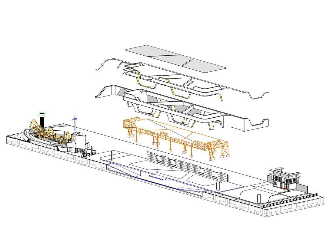
through-out section drawings there’s an express of other disciplines of MEP in depth and more lines are shown from the different layers of walls, floors and roofs. all the components final output are result of the combination between autocad , sketchup imports and revit in place modeling and families.
8. the classic design modeling was an interesting process having the cornices profiles imported from autocad and then into revit as profiles to be used in wall sweeps.
9. in this project it was new to deal with curtain systems and how by using revit to adapt such methodlogy on setting the mechnical system of the cladding and the panles themselves.
18 F.F.L Ground Level 30.00 F.F.L First 510.00 F.F.L Annix Level 930.00 F.F.L Roof Level 1350.00 F.F.L Street Level 0.00 F.F.L Fence Level 460.00 A B C D E F G H I J K 1 A3-03 12 m² BEDROOM 48 m² SITTING AREA 4 m² DRESSING 17 m² BEDROOM 21 m² BEDROOM 59 m² MAIN MAJLIS 17 m² DINING 61 m² LIVING AREA 170.0 420.0 420.0 50.0 430.0 30.0 W10 D35 D25 W16 W11 W06 30.0 10.0 32.0 10.0 32.0 40.5 sections
8
19 F.F.L STREET LEVEL 0.0 F.F.L GROUND LEVEL 120.0 F.F.L FIRST LEVEL 440.0 F.F.L FORTH LEVEL 1400.0 F.F.L SECOND LEVEL 760.0 F.F.L THIRD LEVEL 1080.0 F.F.L FIFTH LEVEL 1720.0 F.F.L ROOF LEVEL 2040.0 F.F.L BASEMENT LEVEL -200.0 1 2 3 4 5 6 1 A3.05 320.0 320.0 320.0 320.0 322.0 318.0 120.0 200.0 OVEREALL DIM. 2040.0 610.0 420.0 570.0 400.0 400.0 OVERALL DIM. 2400.0 19 m² DINNING 1-25 12 m² KITCHEN 1-26 14 m² FOYER 1-01 16 m² BEDROOM 1-07 18 m² LIVING AREA 2-03 12 m² GUEST HALL 2-01 9 m² KITCHEN 2-25 33 m² LIVING AREA 2-18 29 m² GYMNASIUM 0-17 35 m² LOBBY 242 17 m² BEDROOM 0-04 33 m² LIVING AREA 3-18 33 m² LIVING AREA 4-18 9 m² KITCHEN 4-25 9 m² KITCHEN 3-25 23 m² GUEST HALL 3-01 23 m² LIVING AREA 4-01 D5 W5 D5 D7 W9 W9 W9 D5 D5 D5 D5 W1 W1 W1 W1 W1 W1 W1 W4 W1 W1 W1 W1 W1 W1 W1 W1 W1 W1 W1 W1 W1 W1 W1 W1 2 A7.00 1 A7.00 3 A6.00 3 A7.00 CW1-11 12 m² GUEST HALL 2-37 12 m² GUEST HALL 2-45 D5 D5
20 F.F.L Side Walk Level 15.00 F.F.L Ground Level 45.00 F.F.L Street Level 0.00 1 2 3 146.5 576.6 423.4 320.0 450.0 4 Top of Ridge @ Formal Living 785.00 1' Attic space for A/C Ducted Units and maintainance VRF/VRV OUTDOOR UNIT 244.0 740.0 45.0 SH05 F F F F W05 W04 D11 F 280.0 2 A5.10 A 29.45 m² FAMILY LIVING A 10.09 m² POWDERPOWDER A 7.81 m² STORAGESTORAGE A 22.82 m² BEDROOM (2) 490.0 220.0 405.0 545.0 280.0 303.0 303.0 303.0 284.2 96.0 80.0 110.0 180.0 120.0 198.4 21.6 112.5 180.0 112.5 119.5 320.0 105.5 A7.02 7 Sim 2 A3.02 Top of Gutter @ Formal Living 505.00 Mechanical Services Floor 390.00 8 1 3 9 4 3 6 5 7 405.0 712.5 170.1 280.0 115.0 345.0 30.0 15.0 308.0 152.0 280.0 45.0 F.F.L Side Walk Level 15.00 F.F.L Ground Level 45.00 F.F.L Ground Level 45.00 F.F.L Street Level 0.00 1 2 3 A7.01 4 Top of Ridge @ Formal Living 785.00 1' 146.5 576.6 423.4 1146.5 363.8 565.0 272.1 120.0 D16 370.0 120.0 565.0 A 23.85 m² KITCHENKITCHEN A 26.09 m² FOYERFOYER 15.0 80.0 182.5 80.0 12.5 91.8 A7.04 3 W13 W11 240.0 2 A3.02 Top of Gutter @ Formal Living 505.00 Top of Ridge @ Bedrooms 780.00 Top of Gutter @ Bedrooms 498.05 240.0 740.0 45.0 Aluminum Standing Seam Metal Roofing sheet Over Rockwool Foil Thermal Insulation- (DIV.076113 Single Skin Eave Gutter, Polyster Coated RAL9003 - (DIV.076113) 12 mm THICK Fibre Cement Exterior Siding 12 mm THICK Fibre Cement Exterior Siding Aluminum Standing Seam Metal Roofing sheet Over Rockwool Foil Thermal Insulation - (DIV.076113) Steel Roof Ridge Flashing Corrugated Flat Metal Deck 375.0 30 cm Wall Coping Stone 4.5 THK Flat on Top 192.0 120.0 120.0 45.0 12 mm Gypsum Board Suspended Ceiling 40.0 95.0 240.0 Security Grill 250.0 33.0 Mechanical Services Floor 390.00 Iron Security Grill 280.0 115.0 345.0 30.0 15.0 243.0 282.0 453.0 73.4 15x120 cm Porcelain Tiles (Special Piece) Planter Box Ceramic Tile Skirting 10 cm High 12 mm Gypsum Board Suspended Ceiling 12 mm Gypsum Board Suspended Ceiling A7.04 2 sections 9
21 F.F.L Ground Level 45.00 2 A5.09 5 7 8 10 320.0 450.0 360.0 325.0 325.0 6 9 3696.5Attic space for A/C Ducted Units and maintainance 303.0 SH03 D10 D22 W07 D09 F F F A 27.11 m² BEDROOM (1) A 33.45 m² MASTER BEDROOM 465.0 150.0 320.0 600.0 130.0 244.2 265.0 240.0 96.0 284.2 0.0 96.0 295.0 152.7 527.0 252.5 180.0 32.5 50.0 70.0 30.0 115.0 90.0 115.0 98.5 132.5 180.3 67.2 59.0 65.0 120.0 A7.05 1 Top of Ridge @ Bedrooms 780.00 Top of Gutter @ Bedrooms 498.05 240.0 60.0 1 2 5 1 9 6 6 1 5 7 625.0 1860.0 282.0 453.0 F.F.L Side Walk Level 15.00 F.F.L Ground Level 45.00 F.F.L Street Level 0.00 D B A 355.0 145.0 230.0 355.0 225.0 C A' B' Top of Ridge @ Formal Living 785.00 A8.08 1 370.0 W11 W12 1 A5.09 A 12.99 m² M. BATH A 5.94 m² W.I.CW.I.C 300.0 W17 410.1 120.0 330.0 300.0 D22 1310.0 219.0 242.5 70.0 140.0 93.0 Attic space for A/C Ducted Units and maintainance Top of Ridge @ Bedrooms 780.00 Top of Gutter @ Bedrooms 498.05 740.0 45.0 Single Skin Eave Gutter, Polyster Coated RAL9003 - DIV.076113 Iron Security Grill Planter Box Security Grill 12 mm Suspended Gypsum Board Ceiling Aluminum Standing Seam Metal Roofing sheet Over Rockwool Foil Thermal Insulation- (DIV.076113) Steel Roof Ridge Flashing Aluminum Standing Seam Metal Roofing sheet DIV.076113 12 mm THK Fibre Cement Exterior Siding Aluminum Standing Seam Metal Roofing sheet Over Rockwool Foil Thermal Insulation- (DIV.076113) Steel Ridge Roof Flashing 240.0 287.0 78.0 375.0 45.0 259.5 30 cm W 4.5 THK Wall Coping Stone Flat on Top 306.2 193.8 145.0 90.0 306.2 428.8 40.0 50.0 80.0 50.0 77.5 240.0 15.0 10.0 30.0 Bench Fitted-In Closet See Details @ Sheet No. (A5.08) 380.0 104.6 60.2 A8.08 3 Sim 2.2 mm Plywood Veneer Panel 2.2 mm Plywood Veneer Panel 96.0 96.0 5.0 282.0 453.0 30.0 15.0 9 mm Cement Board Ceiling 12 mm THK Fibre Cement Exterior Siding 910.0 180.0 150.0
using revit and autocad it was possible to refelect on the production of architectural and construction details for the different projects that were showcased.
The base of the details was modeled in revit mainly. in some cases if needed the model was done in sketchup and imported as a family, usually genereic.
all the annotations (from dimentions line weights, etc...) were done in revit due to the flexability of adding customized detail components.
if needed for extra editing and refinement of the line weights and documenting, the drawings were exported as seperated views or with the sheets.
22 F.F.L Fence Level 460.00 A 3x6x0.2 cm THICKNESS STEEL RECTANGULAR TUBE CLASSIC CLAY ROOF TILES 18 mm THICKNESS PLYWOOD SHEET 3 mm THICKNESS STEEL PLATE WELDED ON STEEL TUBE 3 mm THICKNESS STEEL PLATE ANCHORED ON CONCRETE LINTEL BEAM ANCHORED BOLTS ARCHED CONCRETE LINTEL BEAM - SEE DOOR TYPE C 10.0 30.3 20.0 B 2x2x0.5 cm THICKNESS STEEL ANGLE 20 cm THICKNESS BRICK WALL 3 mm THICKNESS STEEL PLATE EXPANDED METAL MESH 2.5 cm THICKNESS PLASTER GRC OPENING FRAME ANCHORE BOLTS WELD 20.0 15.0 20.0
detailing Heater Filter Trench Channel Light Return Water Pump Return Pipe Line Skimmer Brick Wall
23 A 46.0 15.0 20.1 Brick wall thk 20cm Cavity thk 10cm Wood stud work 5 *8 cm Rock wool thermal insulation Concrete beam 13*40 cm 1.5 14.1 20.0 9.0 10.0 Steel structural column Aluminuml strip flashing Wall side panel facade steel gutter 15 *16 cm Steel beam structure Trapezoidal sheet 27/200 Galvanized plywood thk 2 cm Delta Trela Roof Underlayment for Ventilated 8 mm Rain water pvc pipe D 2" 15.0 30.0 Rain water pvc pipe D 2" Lentel beam 30*40 Aluminum panel cap 20.0 9.0 10.0 2.5 Cavity thk 20cm 15.5 39.0 F.F.L Ground Level 45.00 Ground T.O.C 35.00 IN OUT A8.01 2 A8.01 3 W16 A8.08 2 240.0 19.5 50.5 50.0 89.2 D03 SH01 40.0 40.0 - ALUMINUM STANDING SEAM METAL ROOFING SHEET - DIV.076113 12 mm THICK FIBRE CEMENT EXTERIOR SIDING - DIV9 - ALUMINUM STANDING SEAM METAL ROOFING SHEET - DIV.076113 OVER ROCKWOOL FOIL FACED DIV.072100 - SINGLE SKIN EAVE GUTTER , POLYSTER COATED RAL 9003DIV.076113 40.0 16.0 SUSPENDED GYPSUM BOARD CEILING 50.0 FOLDING SHUTTERS CONCRETE LINTEL BEAM 462.4 FORMAL LIVING Top of Gutter @ Formal Living 505.00 - DOUBLE GLAZED ,TEMPERE D GLASS ,SLIDING ALUMINIUM DOORDIV.081116
with revit it’s essential to model specific and preferable families that aren’t available by defualt nor online, in the local templates, that are key components that define the design.
as shown there’re different examples of dynamic components and adaptive from openings, furniture, architectural and structural components.
24
families
25
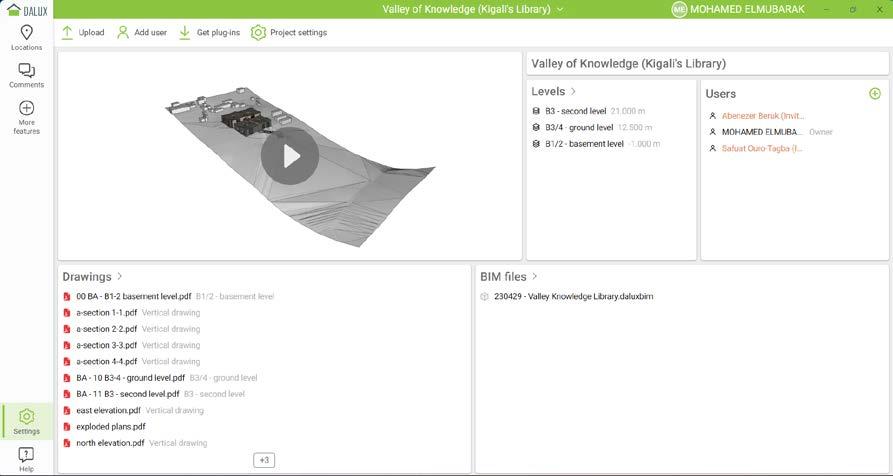
a complementry part to the modeling and drawings is the management of the design and project through software like dalux , in which was done through various projects from time and resources management, and real time simulations of the construction process using synchro to BOQ using revit . the use of active house was critical sometime to the assessment of building energy consumption and relative comparison to the respected standards.
26 8/11/2021 8:16:51 AM 1 : 25 8/11/2021 AM WINDOWS & CURTIN WALLS SCHEDULE SALMAN Al-JERAISY VILLA M.W. Rawan Mohamed A4.02 Riyadh, Al Aqiq, Saudi Arabia MR SALMAN Al-JERAISY ISSUED FOR CONSTRUCTION
revit scheduling
synchro


27 ID Name Duration Start Finish 3D Resources 1 EXV Excavation 30d 09:00 7/12/2023 17:00 8/22/2023 (5) 2 EXV01 Excavators 30d 09:00 7/12/2023 17:00 8/22/2023 3 3 EXV02 First Phase 15d 09:00 7/12/2023 17:00 8/1/2023 1 4 EXV03 Second Phase 15d 09:00 8/1/2023 17:00 8/21/2023 1 5 FND Foundation 52d 09:00 1/10/2024 17:00 3/21/2024 (20) 25 BLD Building Super Structure 317d 09:00 3/21/2024 17:00 6/6/2025 (528) 26 EQ01 Cranes 317d 09:00 3/21/2024 17:00 6/6/2025 2 27 EQ02 Concrete Pump 160d 09:00 3/21/2024 17:00 10/30/2024 1 28 BLD01 Building Block 1 159d, 7h, 59m 09:00 3/21/2024 16:59 10/30/2024 (151) 78 BLD02 Building Block 2 159d, 7h, 59m 09:00 3/21/2024 16:59 10/30/2024 (115) 194 EQ03 Concrete Pump 137d 09:00 10/31/2024 17:00 5/9/2025 1 195 BLD03 Building Block 3 159d, 7h, 59m 09:00 10/24/2024 16:59 6/4/2025 (154) 234 BLD04 Building Block 4 159d, 7h, 59m 09:00 10/28/2024 16:59 6/6/2025 (104) 235 Slabs 100d 09:00 10/28/2024 17:00 3/14/2025 (10) 242 Walls 131d 09:00 10/28/2024 17:00 4/28/2025 (93) 243 Basement 30d 09:00 10/30/2024 17:00 12/10/2024 (20) 249 Ground 30d 09:00 12/16/2024 17:00 1/24/2025 (15) 254 First 30d 16:59 1/28/2025 16:59 3/11/2025 (23) 260 Second 31d 09:00 3/17/2025 17:00 4/28/2025 (27) 261 ST00641 Exterior Wall (Stone Finish)28d 09:00 3/17/2025 17:00 4/23/2025 12 262 ST00642 Interior Wall (Earth Finish)28d 09:00 3/18/2025 17:00 4/24/2025 4 263 ST00679 Interior Wall 28d 09:00 3/19/2025 17:00 4/25/2025 3 264 ST00643 Interior Wall (Partition) 28d 09:00 3/19/2025 17:00 4/25/2025 4 265 ST00644 Interior Wall (Void) 28d 09:00 3/20/2025 17:00 4/28/2025 4 266 Facade 131d 09:00 10/28/2024 17:00 4/28/2025 (8) 270 Roof 28d 16:59 4/29/2025 16:59 6/6/2025 (1) 272 STR Main Stair 137d 09:00 6/9/2025 17:00 12/16/2025 (186) Jul wk 8 Oct wk 22 Jan 2024 wk 35 Apr wk 48 Jul wk 61 Oct wk 74 Jan 2025 wk 87 Apr wk 100 Jul wk 113 Oct wk 126 Jan 2026 wk 139 Jun 2023 Project title Programme title Client Dated 12/10/2023 Drawn by Administrator Programme No Rev No Rev comments Notes Printed: 23:40 5/13/2023 <C:\Users\moha1\OneDrive Politecnico di Milano\Group 7\057142 Sustainable Technology\Drawings Files\Synchro 4D Pro\Valley Knowledge Library.sp>, Page 1 of 1 ID Name Duration Start Finish 3D Resources 1 EXV Excavation 30d 09:00 7/12/2023 17:00 8/22/2023 5 FND Foundation 52d 09:00 1/10/2024 17:00 3/21/2024 25 BLD Building Super Structure 642d 09:00 3/21/2024 17:00 9/4/2026 (574) 27 EQ02 Concrete Pump 320d 09:00 3/21/2024 17:00 6/11/2025 26 EQ01 Cranes 642d 09:00 3/21/2024 17:00 9/4/2026 83 EQ03 Concrete Pump 323d 09:00 6/11/2025 17:00 9/4/2026 28 BLD01 Building Block 1 159d, 7h, 59m 09:00 3/21/2024 16:59 10/30/2024 (130) 51 BLD02 Building Block 2 159d, 7h, 59m 09:00 10/31/2024 16:59 6/11/2025 (139) 84 BLD03 Building Block 3 159d, 7h, 59m 09:00 6/16/2025 16:59 1/23/2026 (156) 116 BLD04 Building Block 4 159d, 7h, 59m 09:00 1/26/2026 16:59 9/4/2026 (149) 117 Slabs 100d 09:00 1/26/2026 17:00 6/12/2026 (9) 124 Walls 131d 09:00 1/26/2026 17:00 7/27/2026 (138) 125 Basement 30d 09:00 1/28/2026 17:00 3/10/2026 (35) 130 Ground 30d 09:00 3/16/2026 17:00 4/24/2026 (31) 135 First 30d 16:59 4/28/2026 16:59 6/9/2026 (34) 140 Second 31d 09:00 6/15/2026 17:00 7/27/2026 (34) 141 ST00641 Exterior Wall (Ston 28d 09:00 6/15/2026 17:00 7/22/2026 5 142 ST00642 Interior Wall (Earth 28d 09:00 6/16/2026 17:00 7/23/2026 3 143 ST00679 Interior Wall (Partit 28d 09:00 6/17/2026 17:00 7/24/2026 22 144 ST00644 Interior Wall (Void) 28d 09:00 6/18/2026 17:00 7/27/2026 4 145 Facade 131d 09:00 1/26/2026 17:00 7/27/2026 (4) 147 Roof 28d 16:59 7/28/2026 16:59 9/4/2026 (2) 149 STR Main Stair 137d 10:53 9/7/2026 10:53 3/17/2027 (68) 2024 wk 35 2025 wk 87 2026 wk 139 2027 wk 191 Jun 2023 wk 6 Project title Programme title Client Dated 4/18/2027 Drawn by Administrator Programme No Rev No Rev comments Notes Printed: 13:05 5/26/2023 <C:\Users\moha1\OneDrive - Politecnico di Milano\Group 7\057142 - Sustainable Technology\Drawings Files\Synchro 4D Pro\230127 - Valley Knowledge Library.sp>, Page 1 of 1 synchro
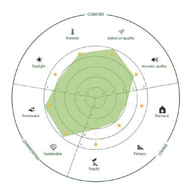
28 Shown cases Results 1 2 3 4 1 2 3 4 1 2 3 4 Therma Indoor a r qua ity Acoust c qual ty Demand Pr mar y Supp y Sustainab e Freshwater Dayl ght COMFORT TNEMNORIVNE YGRENE Librar y Case 1 Librar y Case 1 Librar y Case 1 scheduling dalux active house
29
30 thank you_
