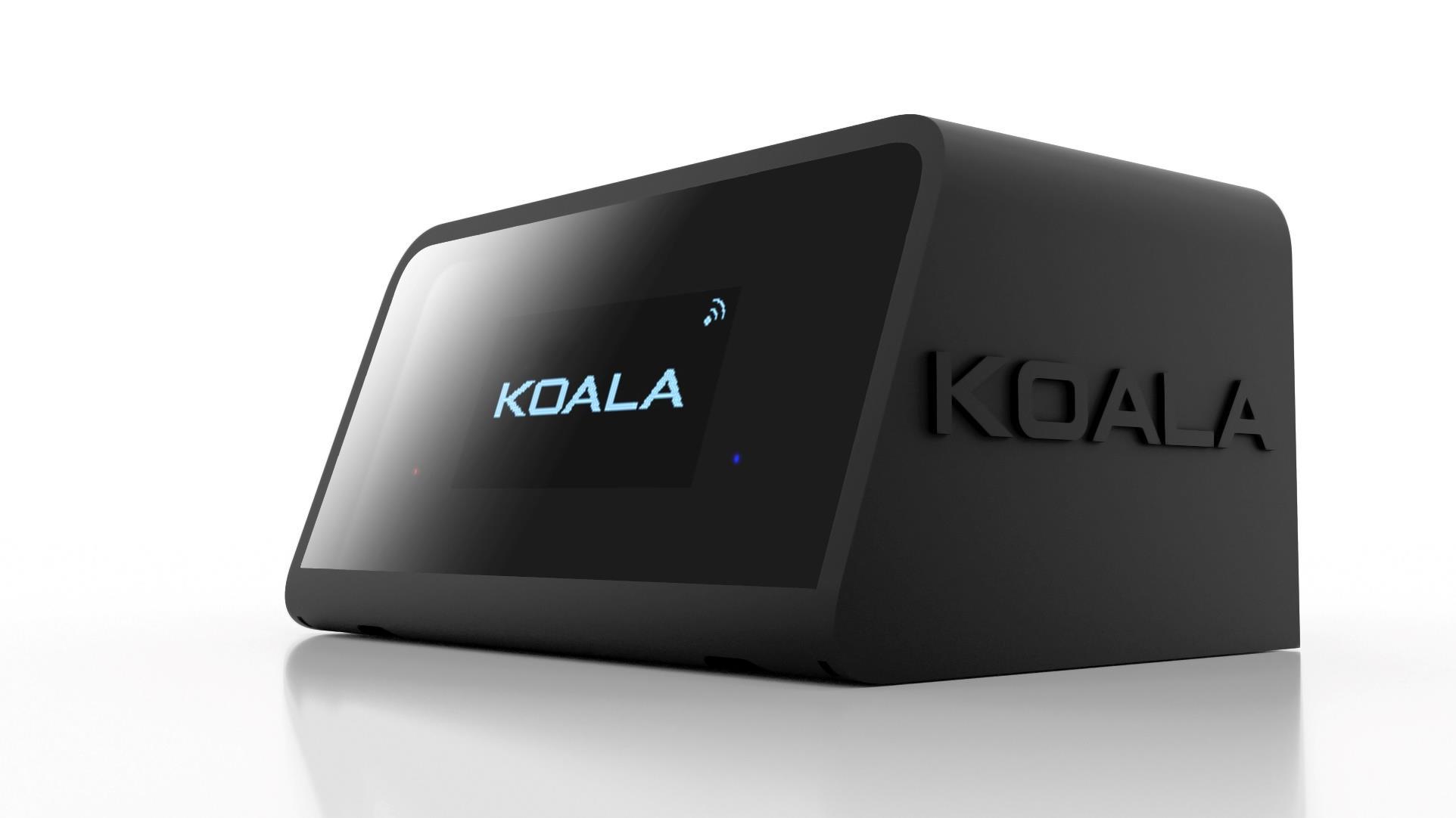
KOALA enables rapid acquisition of PAN, TILT, ZOOM, and FOCUS tracking data with any tripod-mounted camera.
Additionally, with CRANE option it provides XYZ position information.
In a broadcast setting, the system seamlessly operates in SYNC thanks to its dedicated input. Alternatively, in various scenarios, users have the flexibility to generate data at the desired framerate.
Tracking data is accessible through UDP Ethernet, UDP Wi-Fi, and RS485 Serial interfaces. Users can also select between the "FreeD" and "OSC" protocols.
Locally you can reset the LENS and PAN, utilize the AUTOLEVEL function, monitor realtime TRACKING DATA, and check SYNC status.
For remote management, a dedicated web page allows convenient access to all essential settings.
KOALA has been developed based on the feedback from experts in the virtual production industry and it’s designed for simple and intuitive use, aiming to provide a ready-to-use tracking system for a broad range of users in a few minutes.
Easy to understand and compatible with commonly used shooting techniques in virtual production.
KOALA allows more time for productivity and creativity! This manual is based on software version 1410, some variations may exist in alternative versions.
2. MODES AND LICENSES
KOALA has three operating modes: LENS, HEAD, and CRANE. These modes require specific hardware and activation license.
ZOOM AND FOCUS DATA
HEAD PAN, TILT AND ROLL DATA ✔
X, Y, Z POSITION OF CAMERA MOUNTED ON A CRANE
ALL OTHER FUNCTIONS ✔
The license is provided by the manufacturer based on the purchased KIT.
License codes are entered through the SERVICE web page, and it's possible to check which licenses are active by accessing the SERVICE MENU > LICENSES
It is possible to upgrade the license by purchasing the additional option and providing the SERIAL CODE visible on the SERVICE web page or accessing the SERVICE MENU > LICENSES on the display.
3. LAYOUT AND CONNECTIONS
ZIP TIES SLOTS
HOT SHOE RAIL
b. REAR
c. BOTTOM
a. FRONT
4. OPERATING AREA
KOALA has two operating areas: Production and Service.
a. PRODUCTION
When KOALA is powered on by default, it enters in Production
In Production, KOALA generates tracking data. Through the web interface you can set measurements, offsets, ID, sync, etc.
Directly from the display, you can check tracking data, network parameters, and various convenient functions such as Pan and Lens resets or autolevel.
b. SERVICE
In Service, you can find all the settings related to basic configurations, such as licenses, Wi-Fi parameters, mounting type, mode selection, as well as factory data reset and software OTA update.
To enter in Service, you need to press and hold the touch button (on the right side of the display) for 5 seconds during startup or after a reboot. You will notice a small white pixel in the top left corner of the display while holding down the button. Continue holding the button until the service mode is initiated.
Below are listed the functions
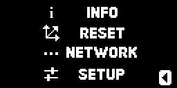
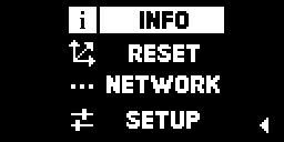
5. DISPLAY MENU
Through the touch button located on the right side of the display, you can interact with the menu and its corresponding functions.
SHORT TOUCH – SELECT
LONG TOUCH – CONFIRM
A short touch on the button reveals the menu, scroll through functions with quick presses, and access them with a long touch of the button
a. SETUP MENU
INFO
RESET
NETWORK
SETUP
DATA
Show real time tracking data and sync status OFFSET
GFX VIEW
VERSION
PAN
LENS
AUX
ETHERNET INFO
Show offset parameters
Show some real time tracking data in graphics mode
Show version of software and hardware
Reset PAN procedure
Reset ZOOM and FOCUS procedure
Reset AUX procedure
Show Ethernet info (IP, destination IP, port and type)
Wi-Fi INFO Show Wi-Fi info (IP, destination IP, port and type)
Wi-Fi ON/OFF
Enable or disable Wi-Fi
STABILIZATION Run Stabilization procedure
AUTOLEVEL
SC. SAVER ON/OFF
Run Autolevel function
Enable or disable display Screen saver REBOOT
Reboot KOALA
NETWORK
SENSOR
LICENSES
RESET / UPDATE
AP MODE ON/OFF
RESET TO DEFAULT
IP
IP - SSID
MOUNT
MODE
Enable or disable Access Point Mode (Wi-Fi)
Reset Ethernet and Wi-Fi parameters to default
Show Ethernet IP
Show Wi-Fi IP and SSID
Change MOUNT position (display LEFT or RIGHT)
Change MODE (LENS, HEAD or CRANE) RECALIBRATION Recalibration sensor (follow this procedure carefully!)
SERIAL CODE
Show CODE for licenses LENS HEAD CRANE
Show licenses STATUS
FACTORY RESET
Reset to default all parameters (Excluding licenses) OTA UPDATE Run OTA Update
6. INSTALLATION AND MEASURES
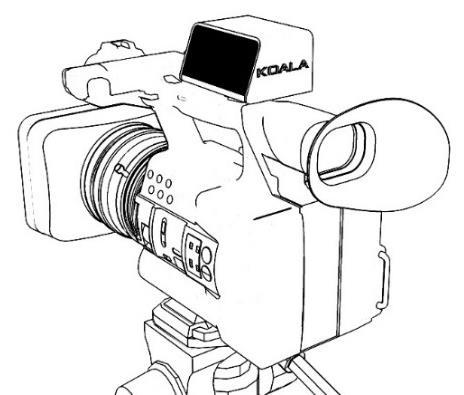
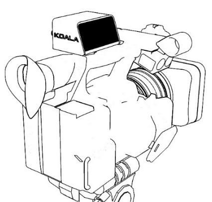
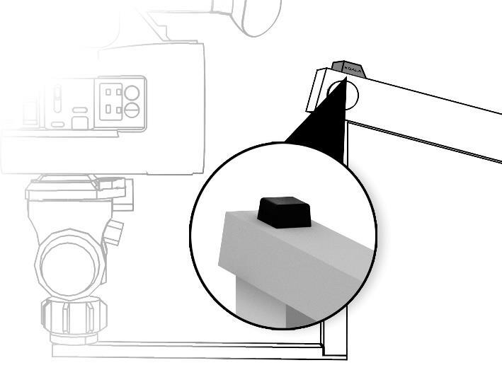
a. MOUNT KOALA
Securely mount KOALA on the top of the camera or in an easily accessible position. The CRANE option should be mounted on the outermost part of the arm with the connectors facing forward. Use the hotshoe adapter in the designated guide or the straps in the respective slots.
Under SERVICE MENU > SENSOR > MOUNT set the KOALA position based on the display orientation: LEFT or RIGHT relative to the camera.
b. WIRE KOALA
Connect KOALA only using official cables and accessories, which are tested and meet the required specifications. The use of cables or accessories not certified by the manufacturer will void the warranty and may cause irreparable damage to KOALA.
example of connecting KOALA
1. Use the supplied AC adapter.
2. Based on your configuration, connect the external encoders provided in the kit or the VIRTUAL cable for your lens in LENS port.
3. Connect the SYNC if necessary, otherwise, set the data rate according to your requirements in SETUP Web Page.
4. If using KOALA in CRANE mode, connect the corresponding accessory with the provided cable in OPTION port.
5. Connect an Ethernet cable from KOALA to your 3D engine and configure the network.
c. AUTOLEVEL
Level TRIPOD, HEAD and CRANE (Crane mode) and proceed to the "AUTOLEVEL" function from the SETUP menu, in this way KOALA will be perfectly leveled with the camera.
NOTE: repeat this operation only if KOALA and/or CRANE Option is reassembled or moved.
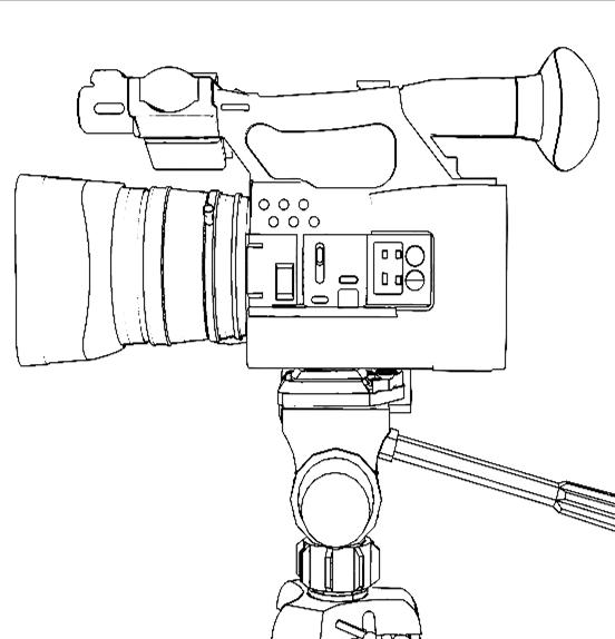
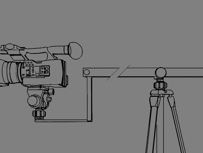
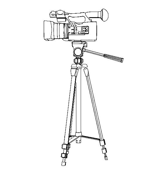
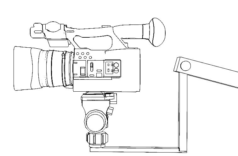
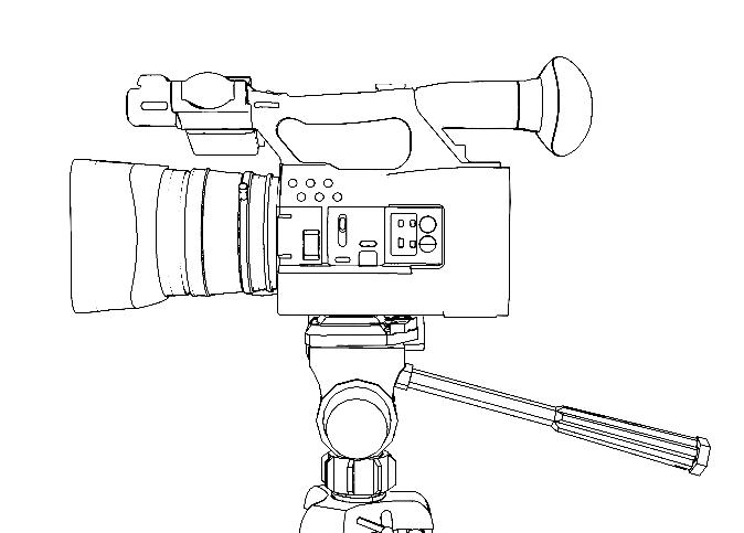
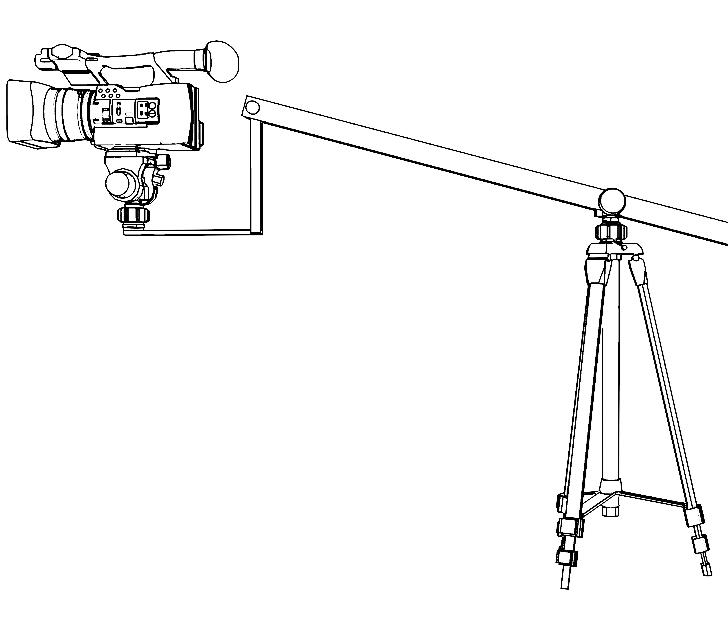
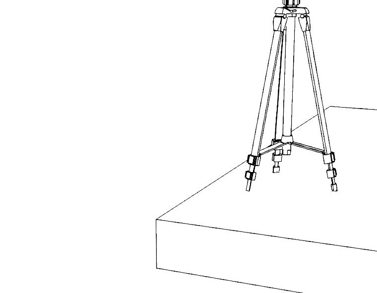
d. MEASUREMENTS
The position of KOALA does not affect the method of taking measurements and the following images depict various types of equipment that may differ in appearance, but the measurement method remains consistent.
HEAD HEAD & CRANE
TRIPOD height (mm)
From the Head’s fulcrum to the floor
HEAD offset (mm)
From the Head’s fulcrum to the Front Crane’s fulcrum. In the example above Y is positive and Z is negative
CMOS offset (mm)
From the Head’s fulcrum to the CMOS position. In the example above Y and Z are positive.
NOTE: the position of the CMOS depends on the camera model used. You can see in some case
CRANE lenght (mm)
From the front Crane’s fulcrum to Tripod’s fulcrum
CRANE
From SET’s center to TRIPOD’s center at the floor In the example above X and Z are positive, Y is negative
a. MOUNT EXTERNAL ENCODERS
7. LENS ENCODERS
b. LENS WITH VIRTUAL OUTPUT
Center of
For a proper pairing of external encoders with lens gears, begin by confirming the correct pitch of the gear, depending on the lens brand. Attach the magic arm to the camera, allowing it to reach the optics with the encoders. Then, couple them securely, ensuring there is no gap between the teeth, and tighten accordingly. Finally, connect the cable to the LENS port on KOALA and proceed to step c.
If your lens is equipped with the 'VIRTUAL' output, you can directly extract data from the internal encoders. Use the cable specific to the lens brand, connect it to the LENS port on KOALA, and you're good to go. Proceed to step c.
c. OFFSET AND DIRECTION
1. Decide if the ZOOM reset point ( zero ) will be wide or tele and bring it to that position
2. Decide whether the FOCUS reset value (zero) will be at infinity or at minimum and set it to that position
3. Reset the lens from MENU > RESET > LENS or from web page with “reset LENS” mode
4. On the display, show the data under MENU > INFO > DATA
5. Move the ZOOM and the FOCUS and check if that values are positive, if they are positive the procedure is finished, vice versa go to point 6
6. Invert the mount of encoders or from the web page set “neg” to ZOOM or FOCUS depending on the encoder to invert
7. Save your settings from web page with “SAVE DATA” mode
8. Return ZOOM and FOCUS to the reset position and restart procedure from step 3.
NOTE: Unlike OSC, the FreeD protocol does not allow negative values for ZOOM and FOCUS. Therefore, KOALA will send a value equal to zero in the FreeD data if the ZOOM or FOCUS encoders were to count negative values.
8. SET PARAMETERS
After taking all measurements and following the procedure for the lens encoders, access the SETUP WEB PAGE (using KOALA's IP displayed in MENU > NETWORK > INFO) where you can configure the following parameters.
NOTE: The available parameters vary depending on the mode (LENS, HEAD, or CRANE).
a.
ENCODERS
ENCODER DIRECTION POS/NEG Set the counting direction to positive or negative
OFFSET number Add a starting offset value when the encoder is reset at 0
b. MEASURES
TRIPOD HEIGHT mm Set the height of the TRIPOD CRANE LENGTH mm Set the length of CRANE HEAD OFFSET mm Set the offset of the HEAD relative to the CRANE CMOS OFFSET mm Set the offset of CMOS relative to the HEAD
ABSOLUTE POSITION mm Set the TRIPOD’s position relative to the center of the SET
c. ETHERNET & Wi-Fi
DHCP ON/OFF Enable or disable DHCP IP 4 bytes Set the Static IP of KOALA (if DHCP is OFF)
DESTINATION IP 4 bytes Set the destination IP of Tracking Data
UDP PORT number Set the port number of UDP Tracking Data
PROTOCOL TYPE FreeD/OSC Set the protocol of UDP Tracking Data
d. SYNC & ID
SYNC µSec Data tx framerate, set to 0 to use external SYNC* ID 1 byte KOALA identification number
Set the parameters and SAVE from dropdown menu on web page (see section 9)
*NOTE: Keep in mind that if set to 0 and the SYNC signal is missing, KOALA will not transmit tracking data.
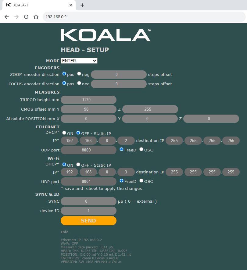
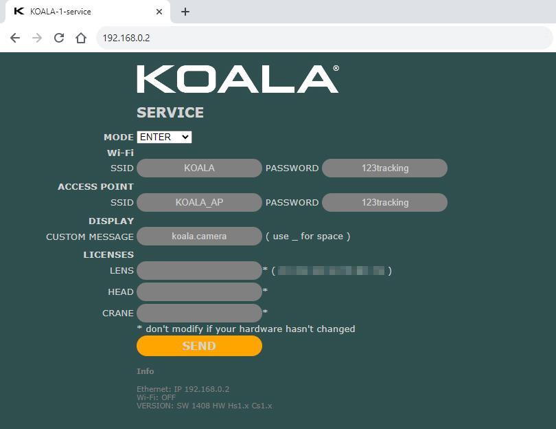
9. SETUP WEB PAGE
When KOALA is connected, open in a browser the KOALA’s IP for Setup Web Page.
this is the setup page of the "HEAD" version, the page changes slightly in the LENS or CRANE versions
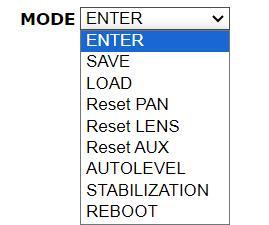
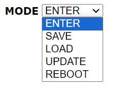
Set the MODE from dropdown menu then click “SEND” button to execute.
ENTER
Use this mode for TEST new data (e.g. measures) or refresh INFO data
SAVE SAVE permanently data in KOALA
LOAD Retrieve saved data
Reset PAN Set Pan orientation to 0°
Reset LENS Set Zoom and Focus encoders count to 0
Reset AUX Set Aux encoder to 0
AUTOLEVEL function to level the values of tilt and roll
STABILIZATION Start procedure to stabilize the drift
REBOOT Reboot KOALA
10. SERVICE WEB PAGE
Power on KOALA in SERVICE (press and hold the touch button for 5 seconds during startup), connect it to your Ethernet or Wi-Fi, and then open the KOALA's IP in a browser to access the Service Web Page.
Set the MODE from dropdown menu then click “SEND” button to execute.
ENTER Use this mode for enter new data or refresh INFO data
SAVE SAVE permanently data in KOALA
LOAD Retrieve saved data
UPDATE Run OTA update
REBOOT Reboot KOALA
11. LED STATUS AND ICONS
The LEDs provide at-a-glance indications of specific KOALA activities
LED A (left) RED
RED
LED B (right)
POWER ON
SYNC FAIL (no OUTPUT data)
BLUE flash every 2” OUTPUT data
2 fast RED flashes SAVE parameters (from WEB PAGE)
2 fast GREEN flashes LOAD parameters (from WEB PAGE)
RED-GREEN-BLUE REBOOT process
PURPLE - 2 long flashes Wi-Fi connection process
WHITE AUTOLEVEL and RESET functions
WHITE flashes STABILIZATION or RECALIBRATION process
GREEN slow blink WARMUP in progress
The display shows notification icons, explained below
ETHERNET cable connected
Wi-Fi is ON and connected
Wi-Fi is ON and disconnected
Wi-Fi is ON in Access Point mode
WARMUP in progress
CRANE unit not connected (in CRANE MODE)
LICENSE FAIL (or MODE selected not licensed)
ETHERNET is waiting DHCP
12. NETWORK
Configure KOALA based on your network settings, including static IP, destination IP, UDP data transmission port, and protocol type.
The default data is as follows:
123tracking
NOTE: When using KOALA via Wi-Fi, there may be interference that compromises stability and accuracy, especially in Access Point mode. Therefore, it is recommended to use a wired connection to prevent interference and ensure uninterrupted data transmission.
The Wi-Fi mode is very useful during first setup and local parameter modification.
13. DATA TRACKING
KOALA sends tracking data in three ways: Ethernet, Wi-Fi, and serial communication.
There are two available protocols: FreeD and OSC
a. FREED
It is the most widely used and supported tracking protocol (in specific, the FreeD D1).
KOALA sends FreeD data in UDP mode (Ethernet and Wi-Fi) and Serial RS485.
For serial connection a specific cable is required to be connected to the 'Option 2' port, and the receiver should be configured as follows:
BAUD RATE: 38400
DATA BIT: 8
PARITY: ODD
STOP BIT: 1
FLOW CONTROL NONE
b. OSC
The data in OSC format is sent via UDP over Ethernet and Wi-Fi in the following manner:
Address pattern (path)
Type and numbers of variables Description
/KOALAx/POS fff (3 Float) X, Y, Z position of camera
/KOALAx/ROT fff (3 Float) Pan, Tilt, Roll of camera
/KOALAx/ZFA iii (3 Integer) Zoom, Focus, Aux values
"x" is the ID of KOALA. For example, if the ID is 3, the pattern will be /KOALA3/…
14. RESET PROCEDURES
The reset procedure is used to set PAN, LENS, and AUX separately to their initial values.
The reset can be performed either through SETUP MENU > RESET or from the web page by selecting the corresponding function from the dropdown menu.
a. PAN
Align the camera with the front of the set when the PAN offset is set to 0. If, for various reasons like obstacles or convenience, this alignment is not possible, reset the position by applying a PAN offset using the Setup web page. Follow the reset procedure as outlined on the display
Please note that when using KOALA in HEAD or CRANE mode, the camera positioning for the reset will vary depending on the configured offsets
b. LENS
Based on the settings determined in the LENS ENCODER section, bring ZOOM and FOCUS to their starting positions and initiate the reset.
c. AUX
The AUX encoder should be brought to its initial position before performing the reset, and this step might also be required for future KOALA implementations.
NOTE: It is recommended to execute the PAN reset following the WARMUP phase to ensure the stabilization of KOALA sensors.
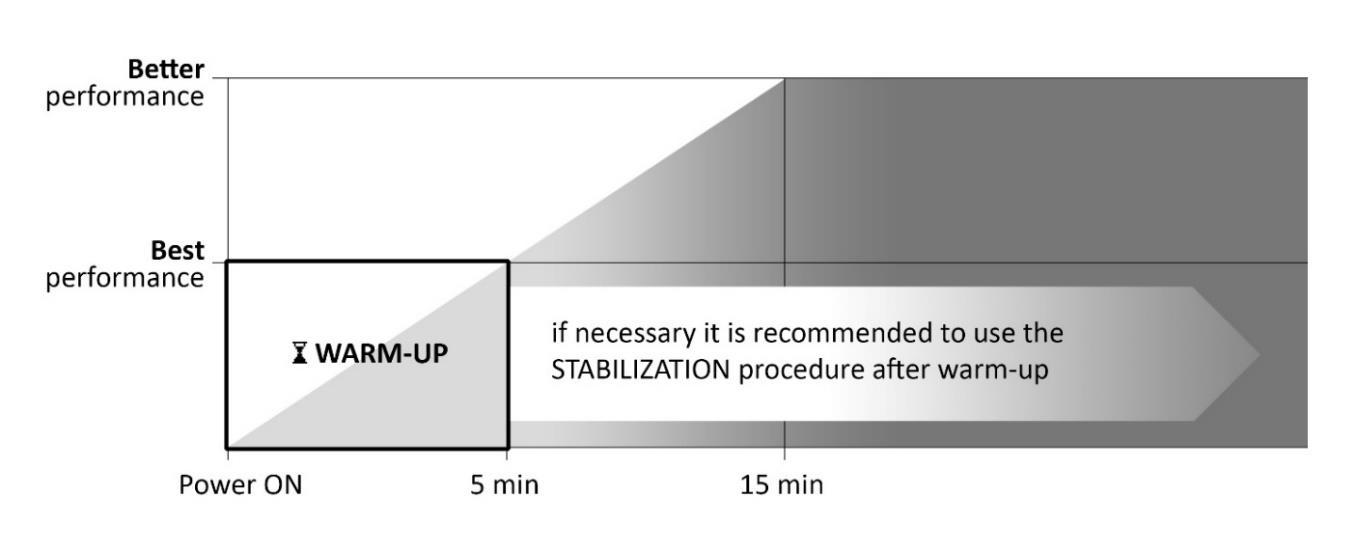
15. WARM-UP AND STABILIZATION
a. WARM-UP
KOALA needs a warm-up time of about 5 minutes for best performance, and after 15 minutes even better.
During the first warm-up phase (5 minutes) the LED B will flash green from slow to fast until the end of the procedure and a filling hourglass icon will appear on the display. Use KOALA during this early stage is not recommended for best performance.
NOTE: Power on KOALA while it is stationary. This ensures accurate and stable data from KOALA right from the initial stages of use. Otherwise, it is advisable to remove the power, wait for a moment, and then power on KOALA when it is not in motion.
b. STABILIZATION
The stabilization procedure is useful when evident pan drifts are noticed such as to compromise the quality of the tracking and it takes only 20 seconds.
To stabilize KOALA, simply keep it still and start the procedure under SETUP MENU > STABILIZATION or from the Setup web page.
If, even after completing the STABILIZATION procedure, no improvement is evident, it is advisable to power off KOALA, wait for a few seconds, and then restart the device.
It is recommended to avoid environments that negatively interfere with KOALA (see section 18)
16. OTHER FUNCTIONS
KOALA provides additional functions:
a. SCREEN SAVER
This function proves useful for two reasons: firstly, like all OLED displays, reducing usage when not necessary is advisable to prolong its lifespan. Secondly, in situations where minimizing light emissions from devices is essential, such as when using KOALA in a theater audience.
The screen saver is enabled from MENU > SETUP > SC. SAVER ON/OFF, and after about 15 seconds of inactivity, the display turns off. To turn the display back on, simply touch the button.
b. CUSTOM MESSAGE
It is possible to customize a message to be displayed on the home page of the display.
This can be useful for visually identifying multiple KOALAs in the same setup, such as specifying the name or number of the camera. It also allows for branding or including reference contacts.
It can be done through the SERVICE web page.
c. RECALIBRATION
Recalibrating the sensors at the core of KOALA's operation is a critical process and should only be carried out on the manufacturer's recommendation in case of sensor malfunctions that could compromise its functionality. The procedure demands precision and should be conducted in an interference-free environment; any inaccuracies in recalibration may lead to unexpected outcomes
This procedure can be executed under SERVICE MENU > SENSOR > RECALIBRATION
Do not proceed with this operation if you are unsure of what you are doing.
17. FACTORY AND NETWORK RESET
To restore KOALA to factory settings, access the SERVICE MENU > RESET / UPDATE > FACTORY RESET function.
It's possible to reset only network parameters using the SERVICE MENU > NETWORK > RESET TO DEFAULT function. (see section 12)
18. PRECAUTIONS AND INTERFERENCES
KOALA is a robust and precise device, but it should be handled with caution and kept away from environmental interferences that could compromise its proper functioning or potentially cause serious damage.
• Electrostatic Currents
• Power Surges
• Magnetic Fields
• Continuous vibrations or strong impacts
• Extreme Temperatures or frequently fluctuations
• Proximity to Heat Sources
• Water or Humid Environments
19. CONNECTORS PINOUT
CONNECTOR DESCRIPTION
DC IN Power
TYPE OF PLUG PINOUT
Male JACK 2.1mm x 5.5mm
LAN Ethernet RJ-45
SYNC Genlock Analog IN (Black Burst)
Male BNC
LENS Encoder ZOOM and FOCUS
OPTION 1
Crane option + AUX encoder
IX40G-A
Internal pin: +5V External pin: GND
OPTION 2
Crane option + RS485 OUT
IX40G-A
Internal: Video Signal
External: GND
1: GND 2: Encoder FOCUS A 3: NC 4: Encoder FOCUS B 5: + 5V 6: GND 7: Encoder ZOOM A 8: NC 9: Encoder ZOOM B 10: + 5V
1: GND 2: Encoder AUX A 3: Reserved 4: Encoder AUX B 5: + 5V 6: GND 7: Reserved 8: + 3,3 V 9: Reserved 10: + 5V
IX40G-A 1: GND 2: RS485 - A 3: Reserved 4: RS485 - B 5: + 5V 6: GND 7: Reserved 8: + 3,3 V 9: Reserved 10: + 5V