
SEAL ONLY Steel Products for Gas Energy Distribution Piping Systems • Bolted Couplings • Insulated Couplings • Compression Couplings • Flange Adapters • Expansion Joints • Line Caps www.dresser.com MIDDLE RING PIPE END SEPARATOR INSULATING GASKET ARMORED GASKET H L A B BOLT FOLLOWER NUT E INSULATING SLEEVE Cast-Iron Pipe Steel Pipe D
Products in this catalog...
Basic Principle of Dresser Couplings ........... Page 1
How to Specify/Order ............................ Page 2-3
Regular Couplings ............................... Page 4-7
Insulating Couplings .............................. Page 8
Insulating Long Couplings ........................ Page 9
Insulating/Reducing Couplings ................. Page 10
Long Body Couplings ......................... Page 11-12
Line Caps .......................................... Page 13
Expansion Joints .................................. Page 14
Flange Adapters ................................... Page 15
Line Cap Plugs Page 16
Dresser End Fittings Inside Back Cover
Customer Service: 1-800-458-2398
Sales Fax: 1-814-362-9344
email: dmdsales@dresser.com
Piping Specialties
AL-CLAD™ Coating Offered as Standard
Dresser AL-CLAD fusion-bonded epoxy coating is offered as standard on the most common Dresser pipe joining products in the most popular sizes featured in this catalog.*
Tough, corrosion-resistant, factory-applied Dresser AL-CLAD epoxy coating has been developed through years of exhaustive testing and field application. Dresser AL-CLAD coating is applied under rigidly controlled conditions, plus it provides superior protection against corrosion no other field coating can match.
*Excludes expansion joints where AL-CLAD coating is optional. Please consult factory for other products in this catalog where AL-CLAD coating is optional.
Dresser Gaskets for Gas Product Applications
Dresser Grade 27 gaskets are rubbercompounded material that will not deteriorate from age or exposure to air under normal storage or use conditions. The rubber gasket material is immune to attack by impurities normally found in natural gas such as odorants, liquid hydrocarbons, carbon dioxide and water. All gaskets meet the requirements of ASTM D2000.
Dresser Grade 27 Armored™ or Armored/Pinned gaskets are specified when electrical continuity is required. The armor is a brass helix which is permanently molded into the tip of the gasket. It provides electrical continuity between the middle ring and pipe. Brass pins leading from the armor to the back face of the gasket provide electrical continuity from the armors to the followers.
Dresser Grade 41 gaskets are specified for insulating coupling applications. In addition to being a dielectric material, they have the same physical and chemical resistance characteristics as Grade 27.
Gasket
Pin penetrates coating on followers and provides electrical conductivity of follower to middle ring
Armored/Pinned Gaskets
Armor provides electrical conductivity from pipe to middle ring
DRESSER COUPLING WITH ARMORED GASKETS
www.dressercouplings.com
Bolt Follower Nut
PIPE PIPE Middle
Ring
SEAL ONLY Steel Products
for Gas Energy Market Piping Systems
The Basic Working Principle of Dresser Couplings
Style 38 Couplings
Page 4-6
STAB-38 Couplings
Page 7
Style 39, 39-40 Insulating
Couplings
Page 8-9
The Dresser Coupling consists of one cylindrical middle ring, two follower rings, two resilient gaskets of special Dresser compound and a set of steel trackhead bolts. The middle ring has a conical flare at each end to receive the wedge portion of the gaskets. The follower rings confine the outer ends of the gaskets. Tightening the bolts draws the follower rings toward each other, compressing the gaskets in the spaces formed by follower rings, middle ring flares and pipe surface producing a flexible, leak-proof seal.
Why Use a Dresser Coupling?
• Dresser offers the broadest line of couplings, including long body, insulating, reducing and transition types.
• Feature Dresser AL-CLAD™ coating as standard in the most popular sizes for optimum protection against highly corrosive soil or aggressive conditions.
• Commonly used sizes range from 1/2” through 72” to cover most applications, and can be furnished in practically any larger size for special requirements
• Dresser couplings are fast and easy to install with any size pipe or tubing having the same OD as steel or cast-iron pipe.
• Wide temperature range from -20°F to +212°F, with pressure ratings to 900 psi.
• Use a Dresser coupling when your line is non-rigid, accepting expansion, contraction, vibration and line deflection.
Style 39-62 Insulating-Reducing Couplings

Page 10
Style 40 Long Couplings
Page 11-12
Style 31 Line Caps
Page 13
Style 63 Expansion
Joints
Page 14
Style 128 Flange Adapter
Page 15
1
Cutaway view shows components of a basic Dresser Style 38 coupling
MIDDLE RING
PIPE PIPE
GASKETS
How to Specify Dresser Products
Specifying Dresser Couplings...
For those who may wish to draw up specifications of a general nature covering Dresser Style 38 couplings, this suggested form is offered:
1.) The pipe coupling shall be of a gasketed, sleeve-type design with diameter to properly fit the pipe. Each coupling shall consist of one (1) steel middle ring, of thickness and length specified, two (2) steel followers, two (2) rubber-compounded wedge section gaskets and sufficient track-head steel bolts to properly compress the gaskets.
The middle ring and followers of the coupling shall be true circular sections free from irregularities, flat spots or surface defects. They shall be formed from mill sections with the follower-ring section of such design as to provide confinement of the gasket. After welding, they shall be tested by cold expanding a minimum of 1% beyond the yield point. The middle ring, inside and out, and followers shall be coated with AL-CLAD™ thermosetting, fusion-bonded epoxy coating material that provides disbondment resistance in cathodicaly-protected systems and resistance to soil stresses and fungi.
The coupling bolts shall be of the elliptic-neck, track-head design with rolled threads. The manufacturer shall supply information as to the recommended torque to which the bolts shall be tightened. All bolt holes in the followers shall be oval for greater strength.
The coupling gaskets shall be composed of a crude or synthetic rubber base compounded with other products to produce a material that will not deteriorate from age, heat, or exposure to air under normal storage conditions. It shall also possess the quality of resilience and ability to resist cold flow of the material so that the joint will remain sealed and tight indefinitely when subjected to shock, vibration, pulsation and temperature or other adjustments of the pipeline.
2.) The couplings shall be assembled on the job in a manner to ensure permanently tight joints under all reasonable conditions of expansion, contraction, shifting and settlement, unavoidable variations in trench gradient, etc. The coupling shall be Dresser Style 38, as manufactured by Dresser Piping Specialties, Bradford, PA, and the necessary quantity shall be furnished
Ordering Specifications for Style 63 Expansion Joints
Dresser Style 63 Expansion Joints are made to order to accommodate your particular requirements. Inquiries or orders for Style 63 Expansion Joints should contain the following information:
(1) Quantity;
(2) Type of pipe: cast-iron, steel, etc.;
(3) Style number and type;
(4) Gas Service: (Note Other)
(5) Maximum working pressure;
(6) Amount of movement to be absorbed by each joint;
(7) Temperature limitations and ranges;
(8) Frequency of cycling;
(9) End preparation of slip or tail pipe—beveled for welding, flanged, other;
(10) Remarks, unusual installations, and list support methods of line and joint.
Expansion Joints
The proper type of expansion joint to use and the method of anchoring and connecting it into a line depend upon the conditions of service and type of installation, as well as other joints in the line. The most effective use of Style 63 expansion joints usually requires an engineering recommendation. For that reason, a complete description of the installation should be submitted, with sketches or working drawings, if possible. Special joints may also be made for unusual conditions.
Dresser Type 1 and Type 3 expansion joints are designed to accommdate 10” of movement as standard. Type 2 and Type 4 expansion joints are designed to accommodate 8” of movement–4” at each end–and the Type 2 must be anchored. If not, a maximum of 4” can be absorbed.
2
©2008 Dresser, Inc.
How to Specify Pipe Ends for Dresser Couplings
How to Specify Ends* on Steel Pipe
On orders and in specifications, the ends on steel pipe to be used with Dresser couplings may be specified briefly as follows:
• The pipe shall be furnished with plain ends for Dresser couplings in accordance with A.P.I. (American Petroleum Institute) Line Pipe Specifications; OR
• The pipe shall be furnished with plain ends for Dresser couplings in accordance with A.W.W.A. (American Water Works Association) Steel Water Pipe Specifications.
If specifications are to be detailed, the following may be used:
For pipe above 5” OD to 10-3/4” OD inclusive:
• The pipe shall be sufficiently free from indentations, projections or roll marks for a distance of 8” from the end of the pipe to make a tight joint with the rubber-gasket type of coupling. The outside diameter of the pipe shall not be more than 1/64” smaller than the nominal outside diameter for a distance of 8” from the end of the pipe and shall permit the passing for a distance of 8” of a ring gauge which has a bore 1/16” larger than the nominal outside diameter of the pipe. The minimum outside pipe diameter shall be determined by the use of a steel tape circumferentially applied to prevent the shipment of undersize, outof-round pipe which, if measured diametrically through the maximum diameter or checked with a No-Go ring gauge, might appear within the specified tolerance.
For pipe larger than 10-3/4” OD:
• The pipe shall be sufficiently free from indentations, projections or roll marks for a distance of 8” from the end of the pipe to make a tight joint with the rubber-gasket type of coupling. The outside diameter of the pipe shall not be more than 1/32” smaller than the nominal outside diameter for a distance of 8” from the end of the pipe and shall permit the passing for a distance of 8” of a ring gauge which has a bore 3/32” larger than the nominal outside diameter of the pipe. The minimum outside pipe diameter shall be determined by the use of a steel tape circumferentially applied to prevent the shipment of undersize, outof-round pipe which, if measured diametrically through the maximum diameter or checked with a No-Go ring gauge, might appear within the specified tolerance.
*While Dresser couplings require only plain-end pipe, other kinds of pipe ends (such as threaded, beveled or grooved) can be used if such pipe is already on hand.
How to Specify Ends on Cast/Ductile Iron Pipe
On orders and in specifications, the ends on cast or ductile iron pipe to be used with Dresser couplings may be specified briefly as follows:
• The pipe shall be furnished with plain ends for Dresser couplings in accordance with A.G.A. (American Gas Association)
Specifications on Tolerances; OR
• The pipe shall be furnished with plain ends for Dresser couplings in accordance with A.W.W.A. (American Water Works Association) specifications on tolerances.
If further specifications are desired, the following may be added:
• The pipe shall be smooth and round for a distance of 8” from each end. The maximum plus or minus variation from nominal outside diameters for each size shall not exceed dimensions as shown in chart at right.
• The maximum outside pipe diameter shall be such as to permit the passing of a ring gauge having an internal bore not greater than .01” larger than the maximum allowable outside diameter of the pipe. This ring gauge shall go over the end of the pipe for a distance of 8” for all sizes up to and including 24” and for a distance of 12” on sizes above 24”.
• The minimum outside diameter shall be determined by use of a steel tape circumferentially applied to prevent the shipment of undersized, out-of-round pipe which, if measured diametrically through the maximum diameter or checked with a No-Go ring gauge, might appear within the specified tolerance.
Maximum Size Variation 3” - 16” .06” 18”- 24” .08” 30”- 42” .10” 48” .12” 54”- 60” .15” 3 ©2008 Dresser, Inc.
Style 38 Couplings
Proven by years of service on all kinds of pipe, Dresser Style 38 couplings provide flexible, leakproof connections that last the life of the pipe. No costly threading, beveling, exact pipe fitting or alignment is required. The resilient Dresser gaskets absorb vibration and pipe movement and permit curves to be laid with straight pipe lengths. Installation is safe and sure. There’s no hazard to workmen or delays due to weather.
NOTE: Commonly used sizes are listed in the tables, but couplings can be furnished for practically any size or special condition.
Materials of Construction
Followers: AISI C1012 or ASME SA36
(Ductile Iron or Malleable Iron for 1/2” thru 1-1/2”)
Middle Ring: ASTM A513, ASTM A635 or ASME SA675 GR60
Bolts: ANSI A21.1
Gasket: Grade 27 BUNA S (Armored/Pinned)
Style 38 Couplings
Sizes and Specifications for Steel Pipe
Steel Pipe Sizes Continue on Page 5
4
BOLT Pipe O.D. Pipe Outside Middle Ring Bolts2 Working Approx. Nominal Pipe Thickness No./Diam. Pressure4 Weight Size Diameter & Length x Length Diam. Length3 Lbs. per Each (In) (OD) (A&B)1 (D&E) (H) (L) Sq.In. (Lbs.) 1/2 .840 .156 x 3-1/2 2–1/2 x 6 3-1/2 8 150 2 3/4 1.050 .156 x 5 2–1/2 x 7-1/4 3-13/16 8-1/2 150 3 1 1.315 .148 x 5 2–1/2 x 7-1/4 4-1/16 8-1/2 150 4 1-1/4 1.660 .154 x 5 2–1/2 x 7-1/4 4-7/16 8-1/2 150 4 1-1/2 1.900 .165 x 5 2–1/2 x 7-1/4 4-3/4 8-1/2 150 5 2 2.375 .154 x 5 2–5/8 x 8-1/4 6 9-1/2 150 7 2 2.375 .154 x 5 3–5/8 x 8-1/4 6-1/4 9-1/2 150 10 2 2.375 .154 x 7 3–5/8 x 10-3/4 6-1/4 11-1/2 150 13 2-1/4 CAS 2.875 .180 x 5 3–5/8 x 8-1/4 7 9-1/2 350 13 3 3.500 .156 x 5 4–5/8 x 6 8 8 350 13 3 3.500 .156 x 7 4–5/8 x 8-1/4 8 9-1/2 350 17 3-1/2 4.000 .188 x 5 4–5/8 x 6 8-5/8 8 400 17 4 4.500 .188 x 5 4–5/8 x 6 9 8 400 16 4 4.500 .188 x 7 4–5/8 x 8-1/4 9 9-1/2 400 23 5-3/16 CAS 5.500 1/4 x 5 4–5/8 x 8-1/4 9-5/8 9-1/2 900 23 5 5.563 1/4 x 5 4–5/8 x 6 10-3/8 8 900 23 5 5.563 1/4 x 7 4–5/8 x 8-1/4 10-3/8 9-1/2 900 25 5-5/8 CAS 6.000 1/4 x 5 6–5/8 x 6 10-5/8 8 900 26 6 6.625 1/4 x 5 6–5/8 x 6 11-1/4 8 900 25 6 6.625 1/4 x 7 6–5/8 x 8-1/4 11-1/4 9-1/2 900 15 7-5/8 8.000 1/4 x 5 6–5/8 x 8-1/4 11-7/8 9-1/2 750 31 8 8.625 1/4 x 5 6–5/8 x 6 13-1/4 7 750 32 8 8.625 1/4 x 7 6–5/8 x 8-1/4 13-1/4 9 750 38 Approx. Dimensions
Single-piece follower construction for 2”-12” couplings
©2008 Dresser, Inc.
Style 38 Couplings (cont’d)
Sizes and Specifications for Steel Pipe
Approx. Dimensions
NOTE: Only couplings for most commonly used steel pipe sizes are shown. Couplings are supplied for ALL SIZES of steel pipe and are regularly available in any special size. Details and prices will be furnished on request for any size of pipe or for any special conditions. Please consult factory.
1- Middle Rings - Thicker or longer than those listed can be furnished. Please specify if pipe stop is required.
2- Bolts - Furnished E-Coated steel as standard.
3- Dimension “L” - Overall length taken with fasteners drawn up finger tight.
4- Working Pressure - Pressure ratings are determined on the basis of Barlow’s formula using a working stress equal to one half the minimum yield of the middle ring material.
Style 38 Small Couplings
Pipe Outside Middle Ring Bolts2 Working Approx. Nominal Pipe Thickness No./Diam. Pressure4 Weight Size Diameter & Length x Length Diam. Length3 Lbs. per Each (In) (OD) (A&B)1 (D&E) (H) (L) Sq.In. (Lbs.) 9-5/8 10.000 1/4 x 5 8–5/8 x 8-3/4 13-7/8 6-7/8 600 39 10 10.750 1/4 x 5 8–5/8 x 6 14-5/8 9-1/2 600 40 10 10.750 1/4 x 7 8–5/8 x 8-1/4 14-5/8 8-7/8 600 49 10 10.750 3/8 x 7 8–5/8 x 8-1/4 14-5/8 11-7/8 600 53 11-5/8 CAS 12.000 1/4 x 7 8–5/8 x 10-3/4 16 11-7/8 550 53 12 12.750 1/4 x 5 8–5/8 x 6 16-3/4 9-1/2 550 45 12 12.750 1/4 x 7 8–5/8 x 8-1/4 16-3/4 11-7/8 550 56 12 12.750 3/8 x 7 8–5/8 x 8-1/4 16-3/4 11-7/8 500 65 14 14.000 1/4 x 7 8–5/8 x 10-3/4 18 9-1/8 500 60 14.000 3/8 x 7 8–5/8 x 10-3/4 18 11-7/8 500 72 16 16.000 1/4 x 7 10–5/8 x 10-3/4 20 9-1/8 450 70 16.000 3/8 x 7 10–5/8 x 10-3/4 20 11-7/8 450 82 18 18.000 1/4 x 7 10–5/8 x 10-3/4 22 9-1/8 400 75 18.000 3/8 x 7 10–5/8 x 10-3/4 22 11-7/8 400 88 20 20.000 1/4 x 7 12–5/8 x 10-3/4 24-1/16 9-1/8 300 86 20.000 3/8 x 7 12–5/8 x 10-3/4 24-1/16 11-7/8 300 90 22 22.000 1/4 x 7 14–5/8 x 10-3/4 26 9-1/8 300 98 22.000 3/8 x 7 14–5/8 x 10-3/4 26 11-7/8 300 108 24 24.000 1/4 x 7 14–5/8 x 10-3/4 28 9-1/8 300 105 24.000 3/8 x 7 14–5/8 x 10-3/4 28 11-7/8 300 120 5
1-1/4” Style 38 showing 2-bolt construction is supplied for 1/2” through 2” O.D. sizes
©2008 Dresser, Inc.
Style 38 3-bolt construction supplied for 2”, 2-1/2” and 3-1/2” O.D. sizes
Style 38 Couplings for Cast-Iron Pipe
Dresser Style 38 Couplings are also available for cast-iron sizes 2” through 72”. These couplings have long been used for joining plain-end cast-iron pipe, combining the advantages of absolutely tight joints and easier, faster pipe joining. Style 38 couplings also permit the salvage and use of random lengths of cast-iron pipe from which bell-ends or cracked sections have been removed.
Materials of Construction
Followers: AISI C1012 or ASME SA36
(Ductile Iron or Malleable Iron for 1/2” thru 1-1/2”)
Middle Ring: ASTM A513, ASTM A635 or ASME SA675 GR60
Bolts: ANSI A21.11
Gasket: Grade 27 BUNA S
Style 38 Couplings for CIP
Sizes and Specifications for Plain-End Cast-Iron Pipe
NOTE: Only couplings for most commonly used pipe sizes are shown. Details and prices will be furnished on request for any size of pipe or for any special conditions. Please consult factory.
6
BOLT Pipe O.D. Pipe Outside Middle Ring Bolts Working Approx. Nominal Pipe Thickness No./Diam. Pressure Weight Size Diameter & Length x Length Diam. Length Lbs. per Each (In) (OD) (A&B)1 (D&E) (H) (L) Sq.In. (Lbs.) 2 2.500 .188 x 5 3–5/8 x 8-1/4 6-1/2 9-1/2 150 10 2-1/4 2.750 .188 x 5 3–5/8 x 8-1/4 7 9-1/2 150 13 3 3.800 .188 x 5 3–5/8 x 8-1/4 7 9-1/2 150 13 4 4.800 .1229 x 5 4–5/8 x 7 9 9-1/2 150 15 4 5.000 .1229 x 5 4–5/8 x 6 9 9-1/2 150 17 6 6.900 1/4 x 5 5–5/8 x 6 11-3/4 9-1/2 150 21 6 7.100 1/4 x 5 5–5/8 x 6 11-3/4 9-1/2 150 21 8 9.050 1/4 x 5 6–5/8 x 8-1/4 13-1/4 9-1/2 150 31 8 9.300 1/4 x 5 6–5/8 x 8-1/4 13-1/4 9-1/2 150 31 10 11.100 3/8 x 7 7–5/8 x 10-3/4 15-9/16 11-7/8 150 47 10 11.400 3/8 x 7 7–5/8 x 10-3/4 15-9/16 11-7/8 150 47 12 13.200 3/8 x 7 8–5/8 x 10-3/4 17-13/16 11-7/8 150 54 12 13.500 3/8 x 7 8–5/8 x 10-3/4 17-13/16 11-7/8 150 54 14 15.300 3/8 x 7 10–5/8 x 10-3/4 19-1/8 11-7/8 150 74 14 15.650 3/8 x 7 10–5/8 x 10-3/4 20-5/8 11-7/8 150 102 16 17.400 3/8 x 7 10–5/8 x 10-3/4 20-1/4 11-7/8 150 88 16 17.800 3/8 x 7 10–5/8 x 10-3/4 22-13/16 11-7/8 150 111 18 19.500 3/8 x 7 12–5/8 x 10-3/4 23-1/2 11-7/8 150 105 18 19.920 3/8 x 7 12–5/8 x 10-3/4 24-15/16 11-7/8 150 124 20 21.600 3/8 x 7 12–5/8 x 10-3/4 25-5/8 11-7/8 150 114 20 22.060 3/8 x 7 14–5/8 x 10-3/4 27-1/16 11-7/8 150 141 24 25.800 3/8 x 7 15–5/8 x 10-3/4 29-3/16 11-7/8 150 134 24 26.320 3/8 x 7 15–5/8 x 10-3/4 31-5/16 11-7/8 150 163
Approx. Dimensions
©2008
Inc.
Dresser,
STAB-38 Couplings for Steel Pipe
The Dresser STAB-38 Coupling is a true “packaged’ pipe joint ready to take out of the carton and slide onto the pipe. Available in sizes from 2” through 12”, these couplings are factory-assembled with no loose parts. It only takes a matter of minutes to make absolutely permanent, tight joints and easier, faster pipe joining. STAB-38 couplings are supplied with armored or armored pinned gaskets and come in clearly marked cartons to simplify warehousing.
Materials of Construction
Followers: AISI C1012 or ASME SA36
(Ductile Iron or Malleable Iron for 1/2” thru 1-1/2”)
Middle Ring: ASTM A513, ASTM A635 or ASME SA675 GR60
Bolts: ANSI A21.11
Gasket: Grade 27 BUNA S (Armored/Pinned)
STAB-38 Couplings
Sizes and Specifications for Steel Pipe
Overall Dimensions
Pipe Middle Ring Bolts Working Shipping Nominal Outside Thickness No./Diam. Pressure Quantity Weight Size Diameter & Length & Length Lbs. per Diam. Length per per Package (In) Inches (A&B) (D&E) Sq. In. (H) (L) Package (Approx.) (Lbs.) 2 2.375 .154 x 5 3–5/8 x 8-1/4 150 6-1/4 7 6 62 2 2.375 .154 x 7 3–5/8 x 10-3/4 150 6-1/4 9 6 72 3 3.500 .156 x 5 4–5/8 x 7 350 6-1/2 7 4 72 3 3.500 .156 x 7 4–5/8 x 8-1/4 350 6-1/2 9 4 72 4 4.500 .188 x 5 4–5/8 x 7 350 8-3/4 7 4 78 4 4.500 .188 x 7 4–5/8 x 8-1/4 350 8-3/4 9 4 84 6 6.625 1/4 x 5 6–5/8 x 7 900 11-1/4 6-7/8 2 52 6 6.625 1/4 x 7 6–5/8 x 8-1/4 900 11-1/4 8-7/8 2 60 8 8.625 1/4 x 5 6–5/8 x 7 750 13-1/4 6-7/8 1 32 8 8.625 1/4 x 7 6–5/8 x 8-1/4 750 13-1/4 8-7/8 1 37 10 10.750 1/4 x 5 8–5/8 x 8-1/4 650 14-5/8 6-7/8 1 42 10 10.750 1/4 x 7 8–5/8 x 10-1/4 650 14-5/8 8-7/8 1 48 12 12.750 1/4 x 5 8–5/8 x 8-1/4 550 16-5/8 6-7/8 1 42 12 12.750 1/4 x 7 8–5/8 x 10-1/4 550 16-5/8 8-7/8 1 48
7
BOLT FOLLOWER NUT MIDDLE RING PLAIN OR ARMORED GASKET Pipe O.D.
STAB 38 Coupling with Single Piece Follower
©2008 Dresser, Inc.
• Couplings
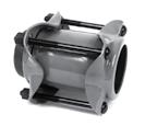
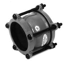
Style 39 Insulating Couplings
For insulation and electric isolation
Dresser Style 39 Insulating Couplings are widely used on lines which are to be electrically isolated for cathodic protection, or for insulating between pipe of dissimilar metals. The Style 39 coupling follows the same basic design and benefits as the Style 38 coupling, but has insulating properties. The insulating gasket has a skirt which extends under the follower ring to insulate it from the pipe. In addition, a “full boot” plastic tubular insulator inside the middle ring assures isolation of pipe ends. Thus, one pipe end is completely insulated from the coupling and opposite pipe end, while the armored gasket on the other end bonds the coupling to the pipe where it can share cathodic protection currents. Style 39 couplings can be virtually used on all sizes of gas and oil pipelines, and can be supplied with insulating features on both ends if required.
Materials of Construction
Followers: AISI C1012 or ASME SA36 (Ductile Iron or Malleable Iron for 1/2” thru 1-1/2”)
Bolts& Nuts: ANSI A21.11
Middle Ring: ASTM A513, ASTM A635 or ASME SA675 GR60
Pipe End Separator & Insulator: Dresser Spec 100 Plastic Insulating Gasket*: Grade 27 Buna S (Armored/Pinned); Grade 41 on Insulating End
Style 39 Insulating Couplings
Sizes and Specifications for Steel Pipe
Approx. Dimensions
*NOTE: Gaskets - Above specifications include Armored Gaskets on conductive end.
3/4 1.050 .120 x 5 2–1/2 x 6-3/4 3-13/16 5-7/8 150 3 1 1.315 .134 x 5 2–1/2 x 6-3/4 4-1/16 5-7/8 150 4 1-1/4 1.660 .140 x 5 2–1/2 x 6-3/4 4-7/16 5-7/8 150 4 1-1/2 1.900 .138 x 5 2–1/2 x 6-3/4 4-3/4 5-7/8 150 5 2 2.375 .154 x 7 3–5/8 x 10-3/4 6-1/4 9 150 12 3 3.500 .156 x 7 4–5/8 x 8-1/4 8 9 350 17 4 4.500 .188 x 7 4–5/8 x 8-1/4 9 9 350 21 6 6.625 1/4 x 7 6–5/8 x 8-1/4 11-1/4 9 900 29 8 8.625 1/4 x 7 6–5/8 x 8-1/4 13-1/4 9 750 36 10 10.750 1/4 x 7 8–5/8 x 8-1/4 14-5/8 8-7/8 600 44 12 12.750 1/4 x 7 8–5/8 x 8-1/4 14-5/8 8-7/8 550 53 14 14.000 3/8 x 7 8–5/8 x 10-3/4 14-5/8 8-7/8 550 82 16 16.000 3/8 x 7 8–5/8 x 10-3/4 14-5/8 8-7/8 450 98 18 18.000 3/8 x 7 8–5/8 x 10-3/4 14-5/8 8-7/8 400 111 20 20.000 3/8 x 7 8–5/8 x 10-3/4 14-5/8 8-7/8 300 122 24 24.000 3/8 x 7 8–5/8 x 10-3/4 14-5/8 8-7/8 300 153 Pipe Middle Ring Bolts Working Approx. Nominal Outside Thickness No./Diam. Pressure Shipping Size Diameter & Length & Length Diam. Length Lbs. per Weight (In) Inches (A&B) (D&E) (H) (L) Sq. In. (Lbs.) 8
MIDDLE RING INSULATOR PIPE END SEPARATOR INSULATING GASKET ARMORED GASKET H L A B BOLT FOLLOWER NUT D E
Style 39 Insulating Coupling with Single Piece Follower
©2008 Dresser, Inc.
Style 39-40 Insulating Long Couplings
For widely separated pipe ends
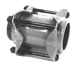
Dresser Style 39-40 Insulated Long Couplings have the same basic design and insulating features as the Style 39, yet are furnished with a longer middle ring body for joining pipe when gaps in pipe ends are wider than ordinary. Though longer, they absorb the same amount of expansion and contraction as the Style 39 coupling, up to 3/8” per joint.
Materials of Construction
Followers: AISI C1012 or ASME SA36
(Ductile Iron or Malleable Iron for 1/2” thru 1-1/2”)
Bolts& Nuts: ANSI A21.11
Middle Ring: ASTM A513, ASTM A635 or ASME SA675 GR60
Pipe End Separator & Insulator: Dresser Spec 100 Plastic
Insulating Gasket*: Grade 27 Buna S (Armored/Pinned); Grade 41 on Insulating End
Style 39-40 Long Body Insulating Couplings
Sizes and Specifications for Steel Pipe
Style 39-40 Long Body Insulating Coupling
Approx. Dimensions
NOTE: Larger sizes and special length bodies can be supplied. *Gaskets - Above specifications include Armored Gaskets on conductive end.
Middle Ring Bolts Working Approx. Nominal Outside Thickness No./Diam. Pressure Shipping Size Diameter & Length & Length Diam. Length Lbs. per Weight (In) (In) (A&B) (D&E) (H) (L) Sq. In. (Lbs.) 1 1.315 .134 x 12 2–1/2 x 14 4-1/16 12 150 4 1-1/4 1.660 .140 x 12 2–1/2 x 14 4-7/16 12 150 4 1-1/2 1.900 .138 x 12 2–1/2 x 14 4-3/4 12 150 5 2 2.375 .154 x 12 3–5/8 x 15 6-1/4 13 150 12 3 3.500 .156 x 12 4–5/8 x 15 8 13 350 16 4 4.500 .188 x 12 4–5/8 x 15 9 13 400 24 6 6.625 1/4 x 16 6–5/8 x 19-1/2 11-1/4 17 900 31 8 8.625 1/4 x 16 6–5/8 x 19-1/2 13-1/4 17 750 38 10 10.750 1/4 x 16 8–5/8 x 19-1/2 14-5/8 17 600 69 12 12.750 1/4 x 16 8–5/8 x 19-1/2 14-5/8 17 550 81 16.000 3/8 x 16 10–5/8 x 19-1/2 15-3/4 17 450 110 9
FOLLOWER BOLT NUT MIDDLE RING INSULATOR PIPE END SEPARATOR INSULATING GASKET ARMORED GASKET H L A E B D
©2008 Dresser, Inc.
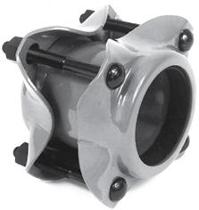
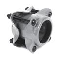
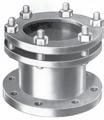
Style 39-62 Insulating/Reducing Couplings
For dissimilar size and pipe end transitions
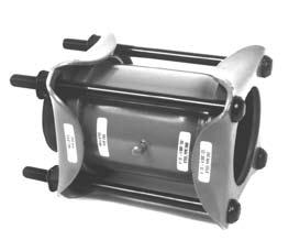
Dresser Style 39-62 Insulating/Reducing Couplings are most widely used where cast-iron and steel pipe are joined in a system. Plus, it eliminates corrosion problems created when joining pipes of dissimilar metals. The insulating gasket is typically furnished on the larger end for cast-iron. A plastic insulating sleeve prevents pipe-end contact with the middle ring, and a sliding pipe end spacer separates the two pipe ends. Type 1 Style 39-62 is available in standard sizes up to 24” I.D.; and Type 3 Style 39-62 features a long-sleeve body in nominal sizes 4” thru 24”.
Materials of Construction
Followers: AISI C1012 or ASME SA36 (Ductile Iron or Malleable Iron for 1/2” thru 1-1/2”)
Middle Ring: ASTM A513, ASTM A635 or ASME SA675 GR60
Bolts: AWWA C 111/ANSI A21.11
Pipe End Separator & Insulator: Dresser Spec 100 Plastic
Gaskets: Grade 27 Buna S (Armored/Pinned); Grade 41 On Insulating End
Style 39-62 Insulating/Reducing Couplings
4 4.80 4.500 1/4 x 12 4–5/8 x 15 9 13 24 6 6.90 6.625 1/4 x 16 6–5/8 x 19-1/2 11-3/4 17 51 8 9.050 8.625 1/4 x 16 6–5/8 x 19-1/2 13-1/4 17 62 10 11.100 10.750 3/8 x 16 8–5/8 x 19-1/2 15-9/16 17 111 12 13.200 12.750 3/8 x 16 8–5/8 x 19-1/2 17-3/4 17 130 16 17.400 16.000 3/8 x 16 10–5/8 x 19-1/2 21-3/8 17 167 20 21.600 20.000 3/8 x 16 12–5/8 x 20 25-5/8 17 211 24 25.800 24.000 3/8 x 16 14–5/8 x 20 29-13/16 17 252 10
2 2.500 2.375 .188 x 5 3–5/8 x 8-1/4 7-3/4 7 12 3 3.800 3.500 .203 x 5 4–5/8 x 8-1/4 7-3/4 7 16 4 4.800 4.500 1/4 x 7 4–5/8 x 8-1/4 9 9 23 4 5.000 4.500 1/4 x 7 4–5/8 x 8-1/4 9 9 25 6 6.900 6.625 1/4 x 7 6–5/8 x 8-1/4 11-3/4 9 27 6 7.100 6.625 1/4 x 7 6–5/8 x 8-1/4 11-3/4 9 27 8 9.050 8.625 1/4 x 7 6–5/8 x 10-3/4 13-1/4 9 34 8 9.300 8.625 1/4 x 7 6–5/8 x 10-3/4 13-1/4 9 36 10 11.100 10.750 3/8 x 7 8–5/8 x 10-3/4 15-9/16 9 58 12 13.200 12.750 3/8 x 7 8–5/8 x 10-3/4 17-3/4 9 83 12 13.500 12.750 3/8 x 7 8–5/8 x 10-3/4 19-5/16 9 85 16 17.400 16.000 3/8 x 7 10–5/8 x 10-3/4 21-3/8 9 20 21.600 20.000 3/8 x 7 12–5/8 x 10-3/4 25-5/8 9 127 24 25.800 24.000 3/8 x 7 14–5/8 x 10-3/4 29-13/16 9 162 Outside Outside Approx. Nominal Diameter Diameter Middle Ring Bolts1 Shipping Size CAST-IRON STEEL Thickness No./Diam. Diam. Length Weight Inches (Inches) (Inches) & Length & Length (H) (L) (Lbs.)
Approx. Dimensions Style 39-62 Insulating/Reducing Coupling Type 3 (Long Body) Sizes and Specifications Type 1 Sizes and Specifications MIDDLE RING Stop PIPE END SEPARATOR INSULATING GASKET ARMORED GASKET H L A B BOLT FOLLOWER NUT E INSULATING SLEEVE Cast-Iron Pipe Steel Pipe D ©2008 Dresser, Inc.
Cast-Iron End Insulating, Steel Pipe End Conductive
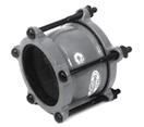
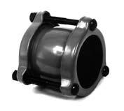
Style 40 Long Couplings
For widely separated pipe ends
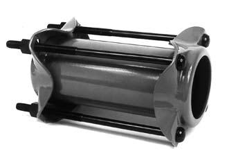
Dresser Style 40 Long Couplings provide a simple and effective method of joining pipe when gaps in pipe ends are wider than ordinary. Style 40 long body couplings are similar in construction to Style 38 couplings, except that middle rings are longer and have a larger belly diameter. Though longer, they absorb the same amount of expansion and contraction as the Style 38 coupling, up to 3/8” per joint.
Materials of Construction
Followers: AISI C1012 or ASME SA36
(Ductile Iron or Malleable Iron for 1/2” thru 1-1/2”)
Middle Ring: ASTM A513, ASTM A635 or ASME SA675 GR60
Bolts: ANSI A21.11
Gasket: Grade 27 BUNA S (Armored/Pinned)
Style 40 Long Couplings*
Sizes and Specifications for Steel Pipe
Style 40 Specifications for Steel Pipe continue on Page 12
*NOTE: Larger sizes and special length bodies are available. Long couplings for CIP are available on request.
11
1/2 .840 .156 x 12 2–1/2 x 14 3-1/2 15-5/8 150 4 3/4 1.050 .156 x 12 2–1/2 x 14 3-13/16 15-5/8 150 5 1 1.315 .148 x 12 2–1/2 x 14 4-1/16 15-5/8 150 6 1-1/4 1.660 .154 x 12 2–1/2 x 14 4-7/16 15-5/8 150 6 1-1/2 1.900 .165 x 12 2–1/2 x 14 4-3/4 15-5/8 150 7 2 2.375 .156 x 12 3–5/8 x 15 6-1/4 17 150 15 2 2.375 .156 x 24 3–5/8 x 28 6-1/4 29 150 33 2-1/2 2.875 .180 x 12 3–5/8 x 15 7 17 350 12 2-1/2 2.875 .180 x 24 3–5/8 x 28 7 29 350 20 3 3.500 .156 x 12 4–5/8 x 12-3/4 8 15 350 23 3 3.500 .156 x 24 4–5/8 x 28 8 29 350 40 3-1/2 4.000 .188 x 12 4–5/8 x 12-3/4 8-5/8 15 350 25 4 4.500 .188 x 12 4–5/8 x 12-3/4 9 15 350 28 4 4.500 .188 x 24 4–5/8 x 28 9 29 350 44 4-1/2 5.000 .229 x 12 4–5/8 x 12-3/4 9 15 400 30 5-3/16 CAS 5.500 .280 x 16 4–5/8 x 19-1/2 9 21 400 42 5 5.563 .280 x 16 4–5/8 x 19-1/2 10-3/8 21 400 51 5-5/8 CAS 6.000 .280 x 16 6–5/8 x 19-1/2 10-3/8 21 935 66 6 6.625 1/4 x 16 6–5/8 x 19-1/2 11-1/4 21 900 54 6 6.625 1/4 x 24 6–5/8 x 28 11-1/4 29 900 60 6-5/8 CAS 7.000 1/4 x 16 6–5/8 x 19-1/2 11-3/4 21 900 54 Pipe Outside Middle Ring Bolts2 Working Approx. Nominal Pipe Thickness No./Diam. Pressure4 Shipping Size Diameter & Length1 x Length Diam. Length3 Lbs. per Weight (In) (OD) (A&B) (D&E) (H) (L) Sq.In. (Lbs.)
Approx. Dimensions
Style 40 Long Coupling with Single Piece Follower
©2008 Dresser, Inc.
Style 40 Long Body Couplings Sizes and Specifications for Steel Pipe (cont’d)
STAB-40 Long Couplings Sizes & Specifications for Steel Pipe
1- Middle Rings - Thicker or longer than those listed can be furnished. Please specify if pipe stop is required (supplied at no extra charge).
2- Bolts - Furnished E-coated steel as standard.
3- Dimension “L” - Overall length taken with fasteners drawn up finger tight.
4- Working Pressure - Pressure ratings are determined on the basis of Barlow’s formula using a working stress equal to one half the minimum yield of the middle ring material.
12 Pipe Outside Middle Ring Bolts2 Working Approx. Nominal Pipe Thickness No./Diam. Pressure4 Shipping Size Diameter & Length1 x Length Diam. Length3 Lbs. per Weight (In) (OD) (A&B) (D&E) (H) (L) Sq.In. (Lbs.) 7-5/8 8.000 1/4 x 16 6–5/8 x 19-1/2 13-1/4 21 750 60 8 8.625 1/4 x 16 6–5/8 x 19-1/2 13-1/4 21 750 63 8 8.625 1/4 x 24 6–5/8 x 28 13-7/8 29 750 85 10 10.750 1/4 x 24 8–5/8 x 28 14-5/8 29 600 109 10 10.750 1/4 x 16 8–5/8 x 19-1/2 14-5/8 21 600 81 11-5/8 12.000 1/4 x 16 8–5/8 x 19-1/2 16 21 550 87 12 12.750 1/4 x 16 8–5/8 x 19-1/2 16-3/4 21-3/4 550 119 12 12.750 3/8 x 24 8–5/8 x 28 17-1/8 29-3/4 550 165 14 14.000 1/4 x 16 8–5/8 x 19-1/2 18 21-3/4 550 130 16 16.000 1/4 x 16 10–5/8 x 19-1/2 21 21-3/4 450 148 16.000 3/8 x 24 10–5/8 x 28 21 29-3/4 450 200 18 18.000 1/4 x 16 10–5/8 x 19-1/2 22 21-3/4 400 175 18.000 3/8 x 24 10–5/8 x 28 23 29-3/4 400 235 20 20.000 1/4 x 16 12–5/8 x 19-1/2 24 21-3/4 300 201 20.000 3/8 x 24 12–5/8 x 28 25 29-3/4 300 269 22 22.000 1/4 x 16 14–5/8 x 19-1/2 26 22-3/4 300 224 22.000 3/8 x 24 14–5/8 x 28 27 30-3/4 300 299 24 24.000 1/4 x 16 14–5/8 x 19-1/2 28 22-3/4 300 240 24.000 3/8 x 24 14–5/8 x 28 29 30-3/4 300 325
Approx. Dimensions
2 2.375 .156 x 12 3–1/2 x 15 6-1/4 17 150 15 2 2.375 .156 x 24 3–1/2 x 28 6-1/4 29 150 33 3 3.500 .156 x 12 4–5/8 x 12-3/4 8 15 350 23 3 3.500 .156 x 24 4–5/8 x 28 8 29 350 40 4 4.500 .188 x 12 4–5/8 x 12-3/4 9 15 350 28 4 4.500 .188 x 24 4–5/8 x 28 9 29 350 44 6 6.625 1/4 x 16 6–5/8 x 19-1/2 11-1/4 21 900 54 6 6.625 1/4 x 24 6–5/8 x 28 11-1/4 29 900 60 8 8.625 1/4 x 16 6–5/8 x 19-1/2 13-1/4 21 769 63 8 8.625 1/4 x 24 6–5/8 x 28 13-7/8 29 769 85 10 10.750 1/4 x 24 8–5/8 x 28 14-5/8 29 632 109 10 10.750 1/4 x 16 8–5/8 x 19-1/2 14-5/8 21 632 81 12 12.750 1/4 x 16 8–5/8 x 19-1/2 16-3/4 21-3/4 520 119 Pipe Outside Middle Ring Bolts2 Working Approx. Nominal Pipe Thickness No./Diam. Pressure4 Shipping Size Diameter & Length1 x Length Diam. Length3 Lbs. per Weight (In) (OD) (A&B) (D&E) (H) (L) Sq.In. (Lbs.) Approx. Dimensions ©2008 Dresser, Inc.
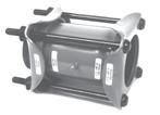
Style 31 Line Caps
For close-off, testing and capping “dead-ends” for future branch extensions
Style 31 Line Caps
Sizes and Specifications for Steel Pipe
Style 31 Line Cap (Vent Optional)
Dresser Style 31 Line Caps are used to close off sections of a pipeline during construction and testing, and to cap off dead-ends in the line for future branch connections. Style 31 Line Caps are made from Style 38 Dresser coupling parts with a convex steel dished head welded into one end of the middle ring. One follower ring is welded to the cap itself, and only one gasket is required.
The Style 31 is regularly supplied with a 1” NPT vent and plug off-center. When ordering, please specify whether vent is to be provided,.
The Dresser Style 31 Line Cap is also available in an insulating design with insulating gasket, insulating sleeve and and pipe-end separator.
WARNING: Style 31 Line Caps must NOT be used under pressure WITHOUT ANCHORAGE OR BLOCKING sufficient to withstand the entire longitudinal thrust due to internal pressure.
Materials of Construction
Followers: AISI C1012 or ASME SA36
(Ductile Iron or Malleable Iron for 1/2” thru 1-1/2”)
Middle Ring: ASTM A513, ASTM A635 or ASME
SA675 GR60
Bolts: AWWA C 111/ANSI A21.11
Gasket: Grade 27 BUNA S (Armored)
NOTE: See inside back cover for Style 1031 Line Cap Plugs
Sizes and Specifications for Cast-Iron Pipe
NOTE: All Style 31 Line Caps supplied with 1” vents as standard. Larger sizes are available. Consult factory for your particular requirements. *Higher pressures available per application.
13
Pipe Outside Middle Ring Bolts Working* Approx. Nominal Pipe Thickness No./Diam. Pressure Weight Size Diameter & Length x Length Lbs. per Each (ID) (OD) (A&B) (D&E) Sq.In. (Lbs.) 2 2.500 .187 x 5 3–5/8 x 8-1/4 150 12 3 3.800 .188 x 5 4–5/8 x 8-1/4 150 14 3 3.960 .203 x 5 4–5/8 x 8-1/4 150 18 4 4.800 .229 x 5 4–5/8 x 8-1/4 150 22 4 5.000 .229 x 5 4–5/8 x 8-1/4 150 23 6 6.900 1/4 x 5 6–5/8 x 8-1/4 150 32 6 7.100 1/4 x 5 6–5/8 x 8-1/4 150 37 8 9.050 1/4 x 5 6–5/8 x 8-1/4 150 42 8 9.300 1/4 x 5 6–5/8 x 8-1/4 150 45 10 11.100 3/8 x 7 8–5/8 x 10-3/4 150 71 10 11.400 3/8 x 7 8–5/8 x 10-3/4 150 72 12 13.200 3/8 x 7 8–5/8 x 10-3/4 150 100 12 13.500 3/8 x 7 8–5/8 x 10-3/4 150 106 14 15.300 3/8 x 7 10–5/8 x 10-3/4 150 120 14 15.650 3/8 x 7 10–5/8 x 10-3/4 150 124 16 17.400 3/8 x 7 10–5/8 x 10-3/4 150 136 16 17.800 3/8 x 7 10–5/8 x 10-3/4 150 147 18 19.500 3/8 x 7 12–5/8 x 10-3/4 150 163 18 19.920 3/8 x 7 12–5/8 x 10-3/4 150 167 20 21.600 3/8 x 7 12–5/8 x 10-3/4 150 183 20 22.060 3/8 x 7 14–5/8 x 10-3/4 150 192 24 25.800 3/8 x 7 15–5/8 x 10-3/4 150 230 24 26.320 3/8 x 7 15–5/8 x 10-3/4 150 235
Pipe Outside Middle Ring Bolts Working* Approx. Nominal Pipe Thickness No./Diam. Pressure Weight Size Diameter & Length x Length Lbs. per Each (ID) (OD) (A&B) (D&E) Sq.In. (Lbs.) 2 2.375 .187 x 5 3–5/8 x 8-1/4 150 12 3 3.500 .188 x 5 4–5/8 x 6 150 12 4 4.500 .188 x 5 4–5/8 x 6 150 18 6 6.625 1-1/4 x 5 6–5/8 x 6 150 30 8 8.625 1-1/4 x 5 6–5/8 x 6 150 37 10 10.750 1-1/4 x 5 8–5/8 x 6 150 39 12 12.750 1-1/4 x 5 8–5/8 x 6 150 47 14 14.000 1-1/4 x 7 10–5/8 x 10-3/4 150 73 16 16.000 1-1/4 x 7 10–5/8 x 10-3/4 150 86 18 18.000 1-1/4 x 7 12–5/8 x 10-3/4 150 98 20 20.000 3/8 x 7 12–5/8 x 10-3/4 150 113 24 24.000 3/8 x 7 15–5/8 x 10-3/4 150 187
©2008 Dresser, Inc.
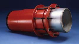
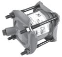
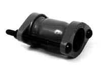
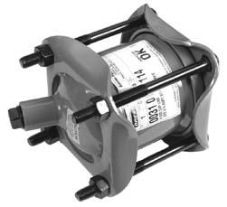
Style 63 Expansion Joints
For absorbing concentrated pipe movement
Dresser Style 63 Expansion Joints provide an economical method of absorbing the concentrated expansion and contraction of piping systems. Aggressive wear and pipe wall failure caused by fatigue of the convoluted surfaces present in rubber accordion or metal bellows types is eliminated with Dresser expansion joints. There is no need for expensive pipe loop systems.
Dresser expansion joints are built to order with limited-movement options, flanged, lock coupled, or weld ends. Provided with rugged welded steel construction, Dresser expansion joints are available in stainless or carbon steel, monel or other alloys for special applications. Available in single-end (Type 1 and Type 3 shown below) with pipe movements up to 10” as standard, and double-end (Type 2 & 4) to accommodate 8” of pipe movement (4” at each end). Larger amounts of movement are available per application.
Standard packing consists of alternate split rubber-compound rings and split jute rings. Special packing and lubrication requirements are custom-matched to specific application requirements.
Dresser expansion joints are available with Dresser AL-CLAD™ coating for optimum protection against coke oven, gas, petroleum and other line content.
Style 63 Type 1 Sizes and Specifications
Overall Dimensions
Materials of Construction
Body: AISI C1006, C1010, C1015, C1025 or ASTM A513 Carbon Steel
Follower: AISI C1012, C1021, ASTM A20 or A36 Carbon Steel
Slip Pipe: Chrome plated
Tail Pipe: AISI C1006, C1010, C1015, C1025 or ASTM A513 Carbon Steel
Bolts & Nuts: ANSI/AWWA C111/ANSI A21.11
Packing: Standard packing is alternate rings of Buna-S and lubricating split jute
Style 63 Type 3 Sizes and Specifications
Overall Dimensions
Type 1 is a single-end expansion joint permitting up to 10” of concentrated pipe movement. Standard packing consists of alternate layers of split resilient sealing rings and jute lubricating rings. Other packing for special conditions can be supplied.
Type 3 is a single-end expansion joint equipped with a limited movement feature to limit the maximum amount of pipe withdrawal. Slip pipes are regularly furnished for Type 3 expansion joints.
14 Pipe Bolts Weight Nominal Outside No./Diam. Per Size Diameter x Length Diam. Length Joint (In) (OD) (A&B) (C) (D) ( E) (Lbs) 3 3.500 4–5/8 x 24 8-1/2 36 46 80 4 4.500 4–5/8 x 24 9-1/2 36 46 90 5 5.563 4–5/8 x 24 10-5/8 36 46 125 6 6.625 6–5/8 x 24 11-3/4 36 46 155 8 8.625 6–5/8 x 24 13-3/4 36 46 205 10 10.750 8–5/8 x 24 15-7/8 36 46 285 12 12.750 8–5/8 x 24 17-7/8 36 46 350 14.000 8–5/8 x 24 19-1/2 36 46 385 16.000 10–5/8 x 24 21-1/2 36 46 430 18.000 10–5/8 x 24 23-1/2 36 46 470 20.000 12–5/8 x 24 25-1/2 36 46 530 22.000 14–5/8 x 24 27-1/2 36 46 590 24.000 14–5/8 x 24 29-1/2 36 46 635 Pipe Bolts Weight Nominal Outside No./Diam. Per Size Diameter x Length Diam. Length Joint (In) (OD) (A&B) (C) (D) ( E) (Lbs) 3 3.500 4–5/8 x 11 8-1/2 36 46 65 4 4.500 4–5/8 x 11 9-1/2 36 46 75 5 5.563 4–5/8 x 11 10-5/8 36 46 110 6 6.625 6–5/8 x 11 11-3/4 36 46 130 8 8.625 6–5/8 x 11 13-3/4 36 46 180 10 10.750 8–5/8 x 11 15-7/8 36 46 250 12 12.750 8–5/8 x 11 17-7/8 36 46 315 14.000 8–5/8 x 11 19-1/2 36 46 340 16.000 10–5/8 x 11 21-1/2 36 46 380 18.000 10–5/8 x 11 23-1/2 36 46 415 20.000 12–5/8 x 11 25-1/2 36 46 470 22.000 14–5/8 x 11 27-1/2 36 46 525 24.000 14–5/8 x 11 29-1/2 36 46 565
©2008 Dresser, Inc.
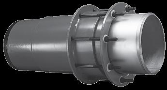
Style 128 Flange Adapter
Fabricated to order from high-strength steel, Dresser Style 128 Flange Adapters afford the engineer a complete size range up to 24” diameter in steel and cast-iron sizes. ANSI B16.5 Class 150 flanges are standard. Other types and classes can be provided on request.
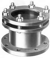
The compression end of the adapter has a Dresser coupling type design utilizing a wedge gasket for an efficent, leak-proof seal. Insulating designs can also be furnished. Larger sizes up to 96” are available upon request.
Materials of Construction
Follower: AISI C1012 or ASME SA36
Body & Flange: ASTM A513, ASTM A635 or ASME SA675 GR60
Bolts & Nuts: Alloy to AWWA C 111/ANSI A21.11
Gasket: Grade 27 BUNA S
Style 128 Flange Adapter*
Sizes and Specifications for Steel Pipe
Style 128 Flange Adapter*
SIzes and Specifications for Cast-Iron Pipe
*Rated 150 psi as standard
Follower Overall Bolt No. of Overall Approx. Approx. Nominal Outside End Bolts Flange Circle Bolt Holes Follower Overall Shipping Size Diameter Body Number Diameter Diameter x Diameter Diameter Length Weight (CIP) (Inches) Thickness Diam. & Length (A) (B) (C) (D) (L) (Lbs) 3 3.74 - 4.02 .188 4–5/8 x 4 7-1/2 6 4 x 3/4” 7-3/4 8-11/16 25 4 4.74 - 5.06 .229 4–5/8 x 4 9 7-1/2 8 x 3/4” 9 9-7/16 30 6 6.84 - 7.16 1/4 4–5/8 x 4 11 9-1/2 8 x 7/8” 11-3/16 9-1/16 36 8 8.99 - 9.36 1/4 6–5/8 x 4 13-1/2 11-3/4 8 x 7/8” 13-1/2 9-1/16 50 10 11.04 - 11.46 3/8 8–5/8 x 4 16 14-1/4 12 x 1” 15-9/16 9-3/16 69 12 13.14 - 13.56 3/8 8–5/8 x 4-1/2 19 17 12 x 1” 17-13/16 9-11/16 95 Follower Overall Bolt No. of Overall Approx. Approx. Nominal Outside End Bolts Flange Circle Bolt Holes Follower Overall Shipping Size Diameter Body Number Diameter Diameter x Diameter Diameter Length Weight (Steel) (Inches) Thickness Diam. & Length (A) (B) (C) (D) (L) (Lbs) 2 2-3/8 .156 3–5/8 x 4 6 4-3/4 4 x 3/4” 6-1/4 8-5/8 14 3 3-1/2 .156 4–5/8 x 4 7-1/2 6 4 x 3/4” 7-3/8 8-13/16 19 4 4-1/2 .188 4–5/8 x 4 9 7-1/2 8 x 3/4” 8-3/4 8-13/16 25 5 5-9/16 1/4 4–5/8 x 4 10 8-1/2 8 x 7/8” 9-5/8 9-9/16 30 6 6-5/8 1/4 6–5/8 x 4 11 9-1/2 8 x 7/8” 11-1/4 9-5/8 38 8 8-5/8 1/4 6–5/8 x 4 13-1/2 11-3/4 8 x 7/8” 13-1/4 9-3/4 52 10 10-3/4 1/4 8–5/8 x 4 16 14-1/4 12 x 1” 14-5/8 9-13/16 58 12 12-3/4 1/4 8–5/8 x 4 19 17 12 x 1” 16-5/8 9-7/8 79 14 1/4 8–5/8 x 4 21 18-3/4 12 x 1-1/8” 18 10 89 16 3/8 10–5/8 x 4 23-1/2 21-1/4 16 x 1-1/8” 20 10-1/16 103 18 1/4 10–5/8 x 4-1/2 25 22-3/4 16 x 1-1/4” 22 10-11/16 112 20 3/8 12–5/8 x 4-1/2 27-1/2 25 20 x 1-1/4” 24-1/16 10-13/16 127 24 3/8 14–5/8 x 4-1/2 32 29-1/2 20 x 1-3/8” 28 11 184
15
FLANGE RING MIDDLE GASKET NUT FOLLOWER LUGS PIPE BOLT
©2008 Dresser, Inc.
Style 1031 & 2090 Line Cap Plugs
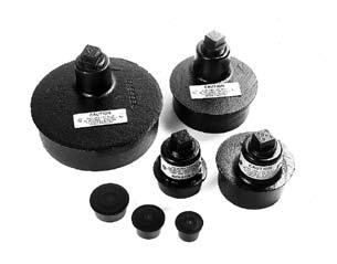
For close off, testing and “dead-ends” on pipe line extensions
For a dependable and gas tight installation, Dresser Line Cap Plugs provide a convenient way to (1) close off sections of pipe during construction, (2) for testing, (3) for use as “dead-ends”, (4) as an end plug fitting for future branch extensions, or (5) for end closures to seal off abandoned lines. Dresser Style 1031 line cap plugs can be furnished with a 1” vent (including a 1” threaded plug) in 2”, 3”, 4” and 6” IPS sizes. The line cap plug can simply be inserted into any standard Dresser bolted coupling including the Style 38, Style 40 Long Body, the non-insulating end of the Style 39 and 39-40, and the steel pipe end of the Style 62 and 39-62 couplings.
Steel line cap plugs (Dresser Style 2090) are furnished without vent for Style 90 compression couplings and are available in 3/4”, 1”, 1-1/4”, 1-1/2” and 2” IPS sizes.
Specifications for Plug with Vent Malleable Iron Material
Style 2090 No Vent
C.R. Steel Material
Other Applicable Warnings for DRESSER Seal-Only Products
16 Follower Gasket Line Plug Bolt ©2008 Dresser, Inc.
Nom. I.D. O.D. A B 2” 2.375 On Center 1-5/8” 3” 3.500 1/2” 1-5/8” 4” 4.500 1” 1-5/8” 6” 6.625 1-5/16” 1-5/8”
Pipe Size
Style 1031 Plug (With Vent)
Nom. I.D. O.D. 3/4” 1.050 1” 1.315 1-1/4” 1.660 1-1/2” 1.900 2” 2.375 Style
Pipe Size Dimensions B A 1" NPT NO! NO!
2090 Plug (Without Vent)
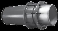
Styles 69, 168, 71 & 72 End Fittings
Custom-built ells, tees, crosses, wyes and laterals
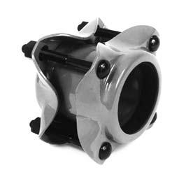
Dresser Compression End Fittings are used to make custom connections, turns and bends in any combination of pipe branches and run outlets. All fittings are of sleeve-type construction and manufactured with the same materials as the standard Dresser Style 38 and Style 40 coupling parts. Each end consists of a steel anchor ring welded to the fabricated sleeve body, a resilient wedge-type gasket with a steel follower, and a set of trackhead bolts—fully assembled and ready to install.
Available in 1-1/4” through 12” size combinations, these fittings absorb all normal pipe movement and deflection while eliminating cutting pipe to exact lengths. When branch ends are left plain, Dresser Style 38 couplings can be furnished for making pipe connections.
Consult Dresser for your particular requirements and ordering specifications.
Customized End Fittings
Sizing Guidelines and Specifications for Steel Pipe*
*Consult factory for exact product specifications for your particular requirements. See additional Style 38 sizes and specification data on Page 4
Pipe Outside Nominal Pipe Sleeve 71 & 72 69 & 168 Size Diameter Body Number Number Style 71 Style 72 Style 69 Style 68 (In) (OD) Thickness Diam. x Length Diam. x Length Tees/Wyes Cross./Lats. 45° Ells 90° Ells 1-1/4 1.660 .154 2 – 1/2 x 7-1/4 4 – 1/2 x 2-1/2 6 6 7 7 1-1/2 1.900 .165 2 – 1/2 x 7-1/4 4 – 1/2 x 2-1/2 7 7 8 8 2 2.375 .156 3 – 5/8 x 8-1/4 4 – 5/8 x 3-1/2 22 38 20 20 2-1/2 2.875 .180 3 – 5/8 x 8-1/4 4 – 5/8 x 3-1/2 33 53 24 24 3 3.500 .156 4 – 5/8 x 6 4 – 5/8 x 3-1/2 37 59 31 27 3-1/2 4.000 .188 4 – 5/8 x 6 4 – 5/8 x 3-1/2 45 70 35 30 4 4.500 .188 4 – 5/8 x 6 4 – 5/8 x 3-1/2 51 72 38 34 4-1/2 5.000 .188 4 – 5/8 x 6 4 – 5/8 x 3-1/2 55 85 43 37 5 5.563 1/4 4 – 5/8 x 6 6 – 5/8 x 3-1/2 66 97 47 46 6.000 1/4 6 – 5/8 x 6 6 – 5/8 x 3-1/2 80 109 62 50 6 6.625 1/4 6 – 5/8 x 6 6 – 5/8 x 3-1/2 90 130 70 55 8.000 1/4 6 – 5/8 x 6 6 – 5/8 x 3-1/2 95 142 75 62 8 8.625 1/4 6 – 5/8 x 6 6 – 5/8 x 3-1/2 139 197 81 73 10.000 1/4 8 – 5/8 x 8-3/4 8 – 5/8 x 3-1/2 176 250 100 83 10 10.750 1/4 8 – 5/8 x 8-1/4 8 – 5/8 x 3-1/2 192 275 122 109 12.000 1/4 8 – 5/8 x 10-3/4 8 – 5/8 x 3-1/2 220 308 138 122 12 12.750 1/4 8 – 5/8 x 8-1/4 8 – 5/8 x 3-1/2 280 396 172 160 14.000 3/8 8– 5/8 x 10-3/4 8 – 5/8 x 4 307 430 203 168 16.000 3/8 10 – 5/8 x 10-3/4 10 – 5/8 x 4 380 520 260 195 18.000 3/8 10 – 5/8 x 10-3/4 10 – 5/8 x 4 490 680 330 250 20.000 3/8 12 – 5/8 x 10-3/4 12 – 5/8 x 4 580 787 390 290 22.000 3/8 14 – 5/8 x 10-3/4 14 – 5/8 x 4 690 948 480 345 24.000 3/8 14 – 5/8 x 10-3/4 14 – 5/8 x 4 790 1085 550 420 Approx. Shipping Weights (Lbs. Each) Bolts per Dresser End Typical Dresser Tee Fitting Configuration
Other DRESSER® Products for Gas Piping Systems
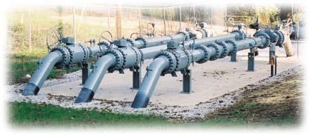
Prefabricated Gate Stations
Dresser® utilizes its unique combination of engineering expertise and custom fabrication capabilities to produce truly “cost effective” prefabricated modular meter sets and gas transmission & regulation gate stations. Our prefabricated sets significantly reduce field installation costs by lowering material and labor costs required for field pipe cutting, beveling, welding, threading, coating and testing. Prefabricated gate stations are custom-built to customer specifications and configurations and offer a variety of valving options to suit your particular M&R system requirements.
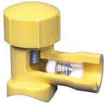
Excess Flow Valves
The safe, economical choice for safety in the event of a catastrophic line rupture.
When a damaged service line allows natural gas leakage into residential or commercial buildings, both lives and property are at risk. Dresser developed its Excess Flow Device to reduce that risk by restricting gas flow automatically when a service line flow condition exceeds the normal operating flow such as would occur with third party damage.
Each Dresser Excess Flow Device is factory-tested to assure it performs within the designated trip flow and bypass flow range and complies with CFR Title 49 D.O.T. 192.381 and MSS-SP-115 governing standards. Fusion, weld and mechanical configurations are available factory-integrated in a variety of carrier fittings. Manufactured for 10 - 60 psi service applications. Consult factory for other pressure ratings.
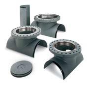
BLACKHAWK Hot Tap and LineStop Fittings
BLACKHAWK™ manufactures hot tapping and line stop fittings and accessories for the natural gas, oil and chemical industries. LS-2 Pressure Control Fittings are available for steel piping systems in threaded sizes from 1/4” through 3” and flange fittings from 4” through 12”.
Full-encirclement LineStop fittings are available in ANSI 150, 300, 600 and 900 Series from 4” through 48” sizes. Split sleeve fittings are also manufactured with side outlet, spherical configurations and with a plain raised face weld neck flange for hot tapping. LineStop Flanges and Completion Plugs are also available. LS-2 Pressure Control Fittings and LineStop Fittings are compatible with specific tapping and plugging equipment and are designed to carry the extra loads imposed during hot tapping and line stopping operations. All fittings meet DOT 192 Federal Regulation for gas pipelines; and DOT 195 Federal Regulation for liquid pipelines and most international codes.
Blackhawk fittings are easily integrated with a variety of Dresser mechanical products.
• Pre-engineered configurations
• Custom-fabricated to your specs and requirements
• Ideally suited for cast-iron piping applications
• Eliminates the need for field welding
• Factory-tested, factory-coated
Piping Specialties
41 Fisher Avenue, Bradford, PA 16701
Phone: (814) 362-9200
Fax: (814) 362-9344
Email: dmdsales@dresser.com
© 2008 Dresser, Inc.
Shown here is a Dresser Style 50 mechanical split sleeve with a Blackhawk 150# LS-2 weld fitting with side outlet, and a Dresser Style 711 coupled PE transition option.
www.dresser.com
FORM 1060 REV. 4-08/R1.5M
