



















❖❖ THE ORIGINAL MAGAZINE FOR MODEL ENGINEERS Vol. 230 No. 4716 5 May – 18 May 2023 Join our online community www.model-engineer.co.uk BASIC CAD Walking through the process Beer Heights Signals Controlling Pecorama’s railway Raised Track Construction Rebirth of a railway in Antwerp Ashpan for Scotsman CAD gets it right first time
SMOOTH, QUIET, HIGH PERFORMANCE VARIABLE SPEED CONTROL FOR LATHES AND MILLING MACHINES
Newton Tesla (Electric Drives) Ltd have been trading since 1987 supplying high power variable speed drives and electric motors to industry up to 500KW so you can be confident in buying from a well established and competent variable speed drive specialist.
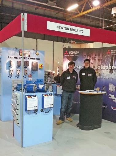

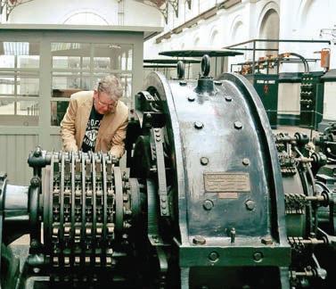
Managing director George Newton, originally from the British Steel industry where he worked with 20,000 HP rolling mill drives is also a skilled machinist and uses his own lathes to design and refine speed controllers especially for the Myford ML7 & Super 7
For the Myford ML7, George and his team produce the AV400, a complete ‘Plug & go’ solution including a new variable speed motor that meets the original Myford motor specification, has the correct 5/8ths sha t diameter and is a direct fit
The ‘AV’ range is extended with the AV550 & AV750 for the Super 7 lathe giving a choice of 3/4HP & 1HP motor power
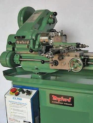
Full Torque is available from motor speed 90 - 1,750 RPM
Advanced Vector control for maximum machining performance
Prewired and programmed ready to go
The AV400/550/750 speed controllers have an impressive 10 year warranty for the inverter and 3 years for the motor (Terms and conditions apply)
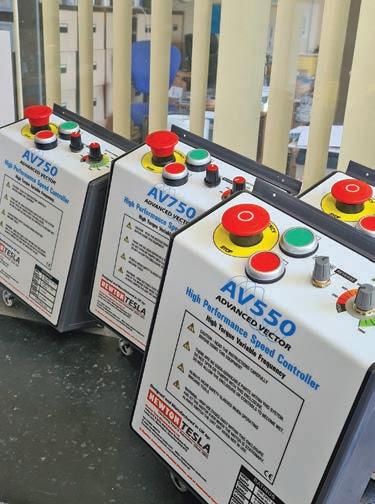
Over 5,000 units supplied to Myford owners
Speed control solutions also available for other lathes including Boxford, Southbend, Colchester, Raglan etc call or email for details
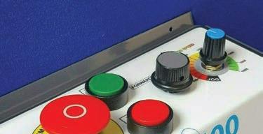
Technical support available by telephone and email 7 days a week


Newton Tesla (Electric Drives) Ltd.

Warrington Business Park, Long Lane, Warrington
Cheshire WA2 8TX, Tel: 01925 444773


Email: info@newton-tesla.com
Visit https://www.newton-tesla.com for more information.
Follow us on Facebook: www.facebook.com/NewtonTeslaLtd
Si (Systèm international d’unités) Newton, unit of mechanical force, Tesla, unit of magnetic field strength

Please mention Model
when replying.
Engineer
New product promotion, AV550 550W motor / inverter for the Myford Super 7. Call for details!
Published by Mor tons Media Group Ltd, Media Centre, Morton Way, Horncastle, Lincs LN9 6JR Tel: 01507 529589 Fax: 01507 371066

© 2023 Mor tons Media ISSN 0026-7325


www model-engineer co uk


EDITORIAL
Editor: Mar tin R Evans
Deputy editor: Diane Carney
Designer: Druck Media Pvt Ltd
Club News: Geoff Theasby
Illustrator: Grahame Chambers
Publisher: Steve O’Hara
CUSTOMER SERVICES
General Queries and Back Issues
01507 529529

Monday-Friday: 8 30am-5pm
Answerphone 24hr
help@classicmagazines co uk
www classicmagazines co uk
ADVERTISING
Group adver tising manager: Sue Keily
Adver tising: Angela Price
aprice@mor tons co uk Tel: 01507 529411

Ad production: Andy Tompkins
By post: Model Engineer adver tising, Mor tons Media Group, Media Centre, Mor ton Way, Horncastle, Lincs LN9 6JR
PUBLISHING
Sales and distribution manager: Carl Smith
Marketing manager: Charlotte Park

Commercial director: Nigel Hole
Publishing director: Dan Savage
SUBSCRIPTION
Full subscription rates (but see page 606 for offer): (12 months, 26 issues, inc post and packing) –
UK £128 70 Expor t rates are also available, UK subscriptions are zero-rated for the purposes of Value Added Tax

Enquiries: subscriptions@mor tons co uk

PRINT AND DISTRIBUTIONS
Printed by: Acorn Web Offset Ltd , W Yorkshire
Distribution by: Seymour Distribution Limited, 2 East Poultry Avenue, London EC1A 9PT
EDITORIAL CONTRIBUTION

Accepted photographs and articles will be paid for upon publication Items we cannot use will be returned if accompanied by a stamped addressed envelope and recorded delivery must clearly state so and enclose sufficient postage In common with practice on other periodicals, all material is sent or returned at the contributor’s own risk and neither Model Engineer, the editor, the staff nor Mortons Media Ltd can be held responsible for loss or damage, howsoever caused The opinions expressed in Model Engineer are not necessarily those of the editor or staff This periodical must not, without the written consent of the publishers first being given, be lent, sold, hired out or otherwise disposed of in a mutilated condition or in other unauthorised cover by way of trade or annexed to or as part of any publication or advertising, literary or pictorial manner whatsoever
648
609
http://www facebook com/modelengineersworkshop


608 SMOKE RINGS
News, views and comment on the world of model engineering
609 THE EATING OF ELEPHANTS
Steve Goodbody argues that anything is possible if you take it a bite at a time
613 A FIVE-INCH GAUGE 0-4-0 PADARN RAILWAY TENDER LOCOMOTIVE
Luker presents Fire Queen, a Welsh slate quarry locomotive
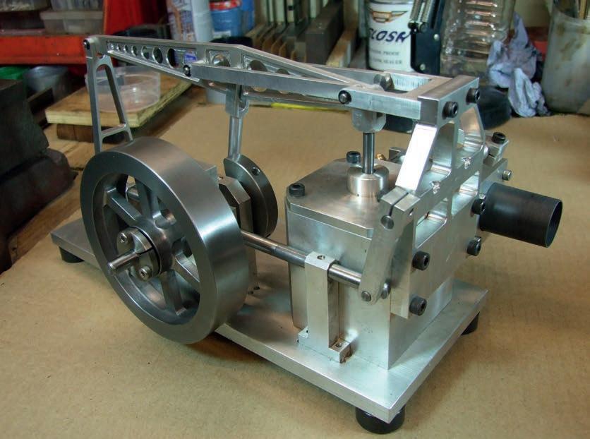
618 GRASSHOPPER BEAM ENGINE
Mar tin Gearing describes a half beam engine suitable for a beginner
622 BASIC OSCILLATOR STEAM ENGINE IN CAD
Luis Trincão leads us through the creation of a 3D CAD model of an oscillating steam engine
626 IN LOCO PARENTIS
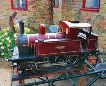
Mike Joseph becomes the carer of an ancient five-inch gauge electric locomotive

629 BEER HEIGHTS LIGHT RAILWAY SIGNALLING
Mike Hanscomb describes the signalling system at the Beer Heights Light Railway at Pecorama in Devon
632 CLUB DIARY Future Events
633 THE 2023 HARROGATE MODEL ENGINEERING EXHIBITION
John Arrowsmith visits a revived show in a renewed hall
638 LNER B1 LOCOMOTIVE
Doug Hewson presents a true to scale 5 inch gauge model of Thompson’s B1
642 POSTBAG


Readers’ letters
643 BOOK REVIEW
John Hobden reads the revised edition of Doug Hewson’s definitive work on five-inch gauge wagon construction
644 KMYCA – A NEW RAISED MINIATURE RAILWAY
Luc Hoorelbeke tells the story of the relocation of the Koninklijke Model Yacht Club’s track in Antwerp
648 FLYING SCOTSMAN IN 5 INCH GAUGE
Peter Seymour-Howell builds a highly detailed Scotsman based on Don Young’s drawings
652 CLUB NEWS
Geoff Theasby compiles the latest from model engineering clubs around the world
O N T H E C O V E R ❖❖ THE OR G NAL MAGAZINE FOR MODEL ENG NEERS –Jo n o r on ne ommunity www mo e -e g nee co uk B A S I C C A D W k ng h o gh he p oce s
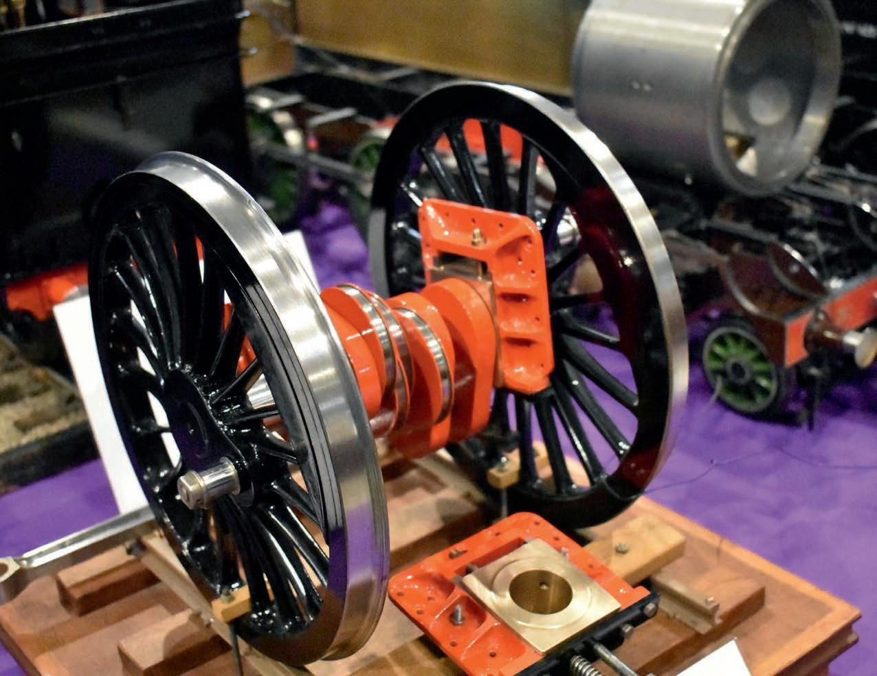
gauge crank axle turned Beer Heights Signals Cont ol ing Pecorama s rai way
Ken Swan from a single piece of bar (photo: John Arrowsmith) Raised Track Construction Reb r th of a rai way n Antwerp Ashpan for Scotsman CAD gets t ght fi st t me

SUBSCRIBE & SAVE UP TO 49% See page 606 for details 603
www.model-engineer.co.uk

Vol 230 No 4716 5 May – 18 May 2023
www.model-engineer.co.uk
. . . A 7¼ inch
by
http://twitter com/ modelengineers This issue was published on May 5, 2023 The next will be on sale on May 19, 2023











P R I N T O N LY Q u a r t e r l y d i r e c t d e b i t fo r £18.00 1 ye a r d i r e c t d e b i t fo r £65.00 1 ye a r c r e d i t / d e b i t c a r d fo r £70.00 P R I NT + D I G ITA L Q u a r t e r l y d i r e c t d e b i t fo r £21.00* 1 ye a r d i r e c t d e b i t fo r £82.99* 1 ye a r c r e d i t / d e b i t c a r d fo r £84.99* D I G I TA L O N LY 1 ye a r d i r e c t d e b i t fo r £49.00* 1 ye a r c r e d i t / d e b i t c a r d fo r £52.95* *Any digital subscription package includes access to the online archive Enjoy 12 months for just £65 GREAT REASONS TO SUBSCRIBE > Free UK deliver y to your door or instant download to your device > Great Savings on the shop price > Never miss an issue > Receive your issue before it goes on sale in the shop SUBSCRIBE AND SAVE L MAGAZINE FOR MODEL ENGINEERS V 9 N 70 4 - 1 m ou online community www m del-enginee c uk EDERATION AGM d Autumn Rally at Little Hay Midlands Show First impressions ❖❖ THE ORIGINAL MAGAZINE FOR M V 3 4 11 J n our n ne c mmu SCOT IMLEC 2023 We invite entries for this year s efficiency compeition We visit a bobb ❖❖ THE ORIGINAL MAGAZINE FOR MODEL ENGINEERS 4712Jo n ou on ne commun ty mode -eng nee Lincolnshire Line Exploring the history of the Lincolnshire Coast Light Railway h u r c h the 150th the s EC 2023 rd to the small ficiency competit on We V t Rye d a l e We tak p Nor th Yorksh re SAVE 49%
w w w.classicmagazines.co.uk /MEDPS 01507 529529 and quote MEDPS Lines open Monday to Friday 8 30am – 5 00pm GMT Offer ends December 31, 2023 Subscriptions will start with the next available issue Direct Debit payments will continue on the agreed plan unless you tell us otherwise To view the privacy policy for MMG Ltd (publisher of Model Engineer), please visit www mortons co uk/privacy Please visit www classicmagazines co uk/terms for full terms & conditions
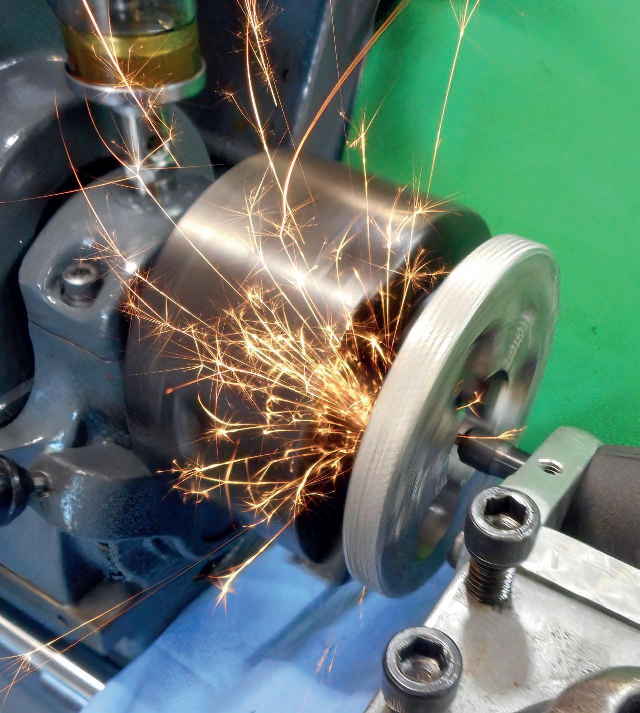
Jaw Regrinding - Pete Barker
Oldest Mountain Railway
Any claim of ‘biggest’, ’smallest’, ‘oldest’ etc is bound to be challenged in time and Roger Backhouse’s asser tion that the Gornergrat railway (M.E.4714, April 7) is the oldest electrically powered mountain railway in the entire world has already met its own challenge

Remarkably, this challenge comes from very close to home, even the British Isles Reader Warwick Casey, a Manxman, points out that the Snaefell Mountain Railway, which is electrically powered, has been operating since 1895, beating the Gornergrat railway by three years I checked and this is indeed so! What would Mr Gornergrat have to say about that? He would claim, of course, that Snaefell is not a mountain A Manxman would reply that it most certainly is, as witnessed by the very name of the railway So many things of this kind depend on defnition and I suppose a mountain in one man’s vocabulary may merit mere molehill status in another’s Model Engineer is not the kind of institution to let these matters rest in limbo Our intrepid assistant editor has therefore set off for the Isle of Man to take a look for herself and will report back in due course on her fndings atch this space
Editor Needs a Bigger House
Having made its way safely through customs (M E 4708,

January 13) my newly acquired archive of Model Engineer has found its permanent home

It now lives in one of my bedrooms where it occupies almost an entire wall So be warned – if you are planning on a similar exercise, be aware that 125 years’ worth of bound magazines requires approximately 30 feet of shelf space or, in IKEA-speak, two whole ‘Billy’ book cases It also weighs of the order of half a ton
Maison Evans also fnds itself hosting a new locomotive, in the shape of a fve-inch gauge arge Prairie from Silver Crest Models I have to say that it is an impressive piece of kit he fnish and the level of det ail are quite impressive for the price. Taking material cost and even a modest rate for the time taken to build a model like this into account, it appears to represent ver y good value for money It is designed in the UK and manufactured in China, hence the relatively low cost I don’t
know how it compares with a locomotive built by a skilled model engineer but I shall be able to say more about that once I have had it in steam
Again, watch this space!


Flying Scotsman

P e t e r S e y m o u r - H o w e l l h a s b e e n f o rc e d , b y a s p e l l o f i l l h e a l t h , to m a r k t i m e f o r a l i t t l e w h i l e o n h i s e xc e l l e n t s e r i e s o n t h e c o n s t r u c t i o n o f a f i n e - s c a l e f i v e - i n c h g a u g e L N E R A 3 l o c o m o t i v e T h i s h a s b e e n c o m p o u n d e d b y a h o u s e m o v e a n d t h e c o n s e q u e n t n e c e s s i t y o f b u i l d i n g a n e w w o r k s h o p P e t e r, t h e re f o re , i s l i ke l y to b e ra t h e r p re o c c u p i e d f o r t h e n e x t fe w m o n t h s , n o t o n l y i n re b u i l d i n g h i s s t re n g t h b u t a l s o i n re b u i l d i n g h i s w o r k s h o p .
T h i s i s q u i t e a c o n v e n i e n t p o i n t to t a ke a b re a t h e r a s F l y i n g S c o t s m a n i s n o w c o m p l e t e ‘ u p to t h e w a t e r l i n e’ ( g i v e s y o u a c h a n c e to c a t c h u p ! ) I s h a l l l o o k f o r w a rd to re s u m i n g t h i s s e r i e s i n d u e c o u r s e I n t h e m e a n t i m e I w i s h P e t e r w e l l f o r a ra p i d re c o v e r y a n d g o o d p ro g re s s o n t h e n e w w o r k s h o p
07710-192953
Model Engineer 5 May 2023
DIANE CARNEY Assistant Editor
MARTIN EVANS Editor
on the mobile number or
to receive your contributions, in the form of items of correspondence, comment
ticles.
Mar tin Evans can be contacted
email below and would be delighted
or ar
MEeditor@mor tons co uk
608
T h e E a t i n g o f E l e p h a n t s
By the early spring of 1985, a merry band of railway constructors had fnally fnished cutting, bending, drilling and Yankeescrewdrivering all the track panels and pointwork needed for a new railway at the Bentley Wildfowl Park in East Sussex We rejoin them as they emerge, blinking and bent double, from their long winter’s labour
Mind the gap
Paul, it turned out (although you wouldn’t know it to look at him) was a closet bridge builder While the rest of us longed to lay track, Paul ached to build buttresses and where we saw topographical obstacles, Paul saw prospects And, as we began the long task of laying, levelling, ballasting and tamping our new track in its new home, Paul would periodically excuse himself, wander over to the ditch between the station and the main circuit and gaze mournfully at the unattractive concrete pipes forming the basis of our culvert-spanning efforts of the previous year, before he joined the club The sight was, I believe, an afront to his dignity
After a few weeks of this slow torture Paul could take no more and, realising he must act before the track reached the culvert, he seized the moment Arriving at Bentley one Sunday morning in April and expecting to be the frst on site, we discovered Paul, deep in the ditch, coffer dam and earthworks in place, applying a fnal coat of stucco to one end of a newly fnished bridge He had clearly been very busy
“Oh – hullo” he started, deep in concentration and not hearing us arrive “I had some free time this week so thought I’d have a go at this And one thing led to another and it
was a shame to stop and so I kept going, and, well, here we are” he concluded, somewhat defensively, lovingly patting his creation all the while
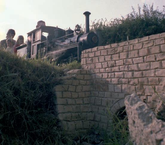
And indeed, there it was! In the space of just one week and without advertisement or fanfare, Paul had singlehandedly deconstructed the frst of our inelegant ditchcrossings and replaced it with a properly constructed bridge, abutments, parapets, wing walls and all It was, not to put too fne a point on it, a truly impressive feat (photo 71)
“Do you think I’ll be allowed to do the other one too?” he asked, concerned that he may have unwittingly overstepped a boundary with his unbidden but herculean effort. We assured him that, yes, we thought it very likely that he would be allowed to build the second bridge; very likely indeed
And thus, Paul became the group’s acknowledged master of bridges, ditches and ponds As time passed and more opportunities presented themselves, his skill and prowess grew but from that

moment it became rare to see anything other than Paul’s upper half at Bentley; his lower quarters were usually sunk into one drainage watercourse or another around the site. Indeed, were I to have passed Paul walking down the street, I am not sure I would have recognised him with his legs on But our little railway gained some lovely bridges as a result
The neighbours from hell
During the course of the preceding year, having borne witness to their ceaselessly destructive attacks on our neatly dug earthworks, we could, beyond all doubt, confrm that rabbits are not railway enthusiasts. However, as we would soon learn, a hundred rabbits are as nothing compared to a single sheep
Now I am sure that this will not come as a surprise but your average sheep, while possessing many fne qualities I am sure, is, as a rule, not very bright Furthermore, they are irresponsible creatures and do not consider the consequences of their actions and, in any
609 E L E P H A N T S www.model-engineer.co.uk >>
P A R T 13 – C R O S S I N G B O U N D A R I E S
Continued from p 565
M E 4715 April 21
Steve Goodbody finds some things are best tackled in small helpings
71
Paul’s frst bridge, shortly after opening day, with a certain Shay passing over the top
orderly farmyard society, the sheep will be the ones with the ASBOs You can count on it
Fortunately, our kin d landlord, knowing their vandalistic tendencies, had provided a neat wood-postand-wire-mesh fence to separate the ovine population, occupying ninety-fve percent of the large pasture, from us, the railway-building populace, who resided in the meagre balance. Sadly, while the latter party, as good citizens, kept to their side of the barricade, our ruminating neighbours, let me tell you, did not
You would think, wouldn’t you, that, having been allocated the signifcant majority of the available buffet and with one patch of grass being very much like another and with a barrier to indicate which was theirs and which was not, that any reasonable animal would be satisfed with its share But no, not sheep You see, sheep, we soon discovered, view a fence as an intriguing puzzle, one to ponder and examine and solve, because sheep, like Sudokuaddicted humans, know there is a solution and will not rest until they fnd it
But that is where our two species diverge and the analogy breaks down
Posit this You, a Sudoku addict, have just completed a particularly taxing puzzle and pleased with your achievement, arise from your armchair to make a nice cup of tea Fifteen minutes later, assuming you have warmed the pot properly and allowed suffcient time for the tea to steep (none of that weak-as-water stuff, if you don’t mind), you return, mug in hand and pick up the puzzle once again Now what happens next? Let me hazard a guess
Firstly, you will no doubt look at the puzzle and, remembering that you fnished it shortly before, as plainly evinced by the numbers on the sheet, recall that it was a tricky and challenging puzzle; you might even congratulate yourself, with a degree of pride, upon fnding its solution Furthermore, you might think to yourself, not unreasonably
‘I did that and
if I had to do that same puzzle again it would be much easier because I discovered the little trick and I can remember the solution ’ And you would be right, wouldn’t you?
But the same reasoning does not apply to a sheep and a fence
A sheep, having spent an enjoyable hour exploring a puzzling barrier and having discovered the tiny gap at the very end where it meets the hedge and having squeezed its way through in triumph and having nibbled the grass on the other side for a few minutes and decided that it tastes just like every other bit of grass it’s ever eaten, will look up, see the fence and say to itself in surprise –‘Now, what on earth is that?’
And then, being an ASBO sheep and seeing that its newly discovered environment contains a long line of neatly ordered gravel among the grassflavoured grass, it will diligently kick and prod and dig at those stones until not one is in its original position and most are scattered widely around the feld For a sheep is a zealous prophet to the great god entropy and craves disorder above all things
Then, having created as much mess and destruction as it possibly can, the sheep becomes aware that several irate humans, presumably annoyed because it’s 1985 and Sudoku hasn’t been invented yet, are shouting and waving and trying to direct its attention towards the large, hinged opening that wasn’t there before so the sheep, for reasons known only to itself and having no recollection as to how it came to be in its new location, runs as fast as it can away from the wideopen gate and then, doublingback, begins to throw itself repeatedly against the woodpost-and-wire-mesh fence, bouncing back and forth like an horizontal trampolinist in a plus-sized Arran sweater. And I know this because, for several weeks that spring, this exact series of events was a regular occurrence
One minute there would be no sheep to be seen anywhere, not for miles around and the next,
having turned our backs to concentrate on a fshplate bolt for just a moment, a stream of flying ballast would announce the arrival of yet another bleating vandal
But one fne Sunday, shortly after Easter, Bill, who had been on holiday and was unaware of our plight, returned to the fold.
Now you may remember that Bill, like TBSITW Barry, barndonor Des and bridge-builder Paul, had joined the gang following our club’s exhibition in Uckfeld the previous autumn And it was Bill, a retired toolmaker with a ready wit and a permanent gleam in his eye, ably supported by Geoff as his double-act partner, who had entertained us with story after story as we assembled the growing mountain of track panels in Des’s barn over the course of that very cold winter
While I desperately wanted to believe every word of every wonderful tale that Bill recounted as we wielded our Yankee screwdrivers and while they always bore a wellpolished sheen of plausibility, there was always that nagging too-good-to-be-true feeling in my mind as I wiped away yet another tear of laughter at the conclusion of each story
Anyway, on the morning of Bill’s return we had been lucky, for the sheep, perhaps sensing that trouble was afoot, were keeping to their side of the demarcation line and generally behaving themselves for a change But sheep will be sheep and eventually the now-familiar sound of high velocity gravel announced that yet another of the blighters had arrived to attack our partly laid railway Sighing as we arose from our kneeling positions beside the track, we abandoned work yet again and headed towards the culprit. And, sure enough and with a snort of disdain, today’s intruder dashed in the wrong direction and began bouncing itself rhythmically against the fence
Now, as was usual at this stage of the proceedings, we surrounded the sweater-clad pinball and, with much waving
of hands and shouting of encouragement, attempted to direct it towards the nowopen gate leading to its pasture beyond The sheep, meanwhile, knowing the rules, wholly ignored our guidance so, following the time-honored pattern, we chased that ruminating pest back and forth along the fence line, Keystone Cops-style, while our nemesis alternately dashed between our legs and bounced itself to nearoblivion against the fence
After fully ten minutes of this sport and with the sheep no closer to the exit, we participants, tired and breathing heavily, paused and readied ourselves for round two However, as the pounding in our ears diminished, we became aware of the unwelcome sound of laughter from somewhere behind Turning, there was Bill, leaning against his spade, clearly enjoying the morning’s entertainment
“It was nice of you to give that sheep some exercise but why don’t you catch it so we can get back to work? ” he asked, unhelpfully, a mirthful tear sliding down his own cheek for a change
The rest of the group looked at each other, wondering who would be frst to reply and whether any of the words would be repeatable in polite company Eventually, Geoff took the bait
“Thanks for the advice, Bill” he began, the only time I ever heard ice in his voice “How do you suggest we do that?”
“Give me a moment”, replied Bill, dabbing his moist eyes with a handkerchief
“We’ll wait”, responded Geof f, frostily
And so, we waited and everyone glared at Bill as he blew his nose with gusto. The sheep, I noticed, looked nervous.
Suddenly, without warning, Bill was off, diving at the menace and grabbing it frmly with both hands, one at front and one at rear Then, in one fluid movement, he hefted the shocked animal into the air, rolled it up and over the fence and dropped it unceremoniously on the far side We, rooted to the spot,
610 Model Engineer 5 May 2023
–
stood with mouths wide open in surprise; it had all happened very, very quickly
Nonchalantly rubbing his hands to remove the lanolin and muck, Bill walked past the silent group, collected his spade, and, with a thoughtful look on his face, turned to face the gawping assembly “Waitdid I ever mention I used to be a shepherd? Well, let me tell you about the time ”
And so, as we walked back to our hastily abandoned trackwork, Bill began his next tale, eyes sparkling as usual as he recounted each improbable detail And, this time, I believed every single word, and, looking over the fence into the feld beyond, I am sure the sheep did too
For, unharmed but embarrassed, I could see that our ASBO friend was breathlessly telling its disappointed colleagues that there was a new sheriff in town
Preparations and debuts
With the sheep now under Bill’s control and an enthusiastic and well-knit team wielding the spanners and lugging the gravel, the day fnally arrived when the last piece of track was laid and the last fshplate nut tightened And at that triumphal moment, with a can of celebratory bitter in Roy’s hand and a single rail bender in mine, we gathered self-consciously before John’s camera and the not-at-allposed photograph 72 provides
the proof for all to see One of the club’s wheelbarrows even managed to creep into the frame, I notice

But of course, that was not the end of the work, in fact it served only to mark the beginning of a new phase because, over the course of the next few months, with the track itself now complete, attention turned fully to the peripherals
First there was a station platform to lay, followed by steps to provide access for the non-mountaineering ridership and, once that was done, a neat picket fence to keep the civilian masses under control
The upper half of Paul was, of course, permanently busy, there being other culverts yet to conquer and Des and his horticulturally talented wife (whose name I unfortunately forget), eagerly set to work creating and tending a splendid rockery and flower garden at the sunny end of the station In short, wherever you looked, the railway was a hive of activity that spring
And, in the meantime, to test our creation, generate some income and, heck, because we all desperately wanted to, we began to run trains
At the start, in addition to the Uckfeld Flyer, the club’s aging but reliable lawnmowerengined stalwart (photo 41 from Part 8), motive power was limited to Peter’s trusty Romulus and Mike’s eager Bridget, whose all-or-nothing regulator required a very careful touch to master
After experimentatio n, we determined that a trip length of three-times-around the circuit was the happy compromise between a journey longenough to please the riders and short-enough to meet demand For our little railway, strategically placed as it was beside the children’s play area, was quickly becoming a popular attraction
It did not take us long to discover that, in the hours following lunchtime when the weather was fne, two steam trains supplemented by the ‘Flyer, were the minimum needed to avoid the creation of a long and oftentimes frustrated queue of prospective passengers However, with only two working steam engines and one ‘Flyer available to the club in total and with the owners of those steam locomotives having occasional non-railway obligations (would you believe), this soon became a challenge to achieve Furthermore, to meet the needs of those thirsty steam locomotives, water had to be hand-carried, in a wearyingly regular succession of fve-gallon containers, from a tap beside the Wildfowl Park’s visitor center located a considerable distance from our railway as my aching arms remember it In short, we had some problems to solve.
Fortunately, solutions to both issues were close at hand, although the second was resolved before the frst because Des, you may recall, laid underground water pipes for a living And so, witnessing the need and with a waterstarved rockery and spousal insistence to force the issue,
Des, our saviour once again, soon had two standpipes installed and ready-to-go, one at each end of the station And, after too many weighty trips back-and-forth to the visitor center, I can honestly say that I have never heard anything so pleasing as the sound of water bubbling from those taps the frst time So, thanks once again Des
And that left only the motive power problem to address Thankfully, model engineers tend to have multiple projects on the go simultaneously and, for us railway-builders, while Bentley was clearly one, the other generally came in the form of a locomotive
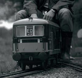
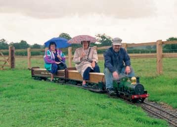
Perhaps unsurprisingly, given the focus and dedication he demonstrated in his bridgebuilding passion, Paul’s was the frst new locomotive to be completed once Bentley became operational and he arrived one day with a unique and perfectly proportioned 7¼ inch gauge Class 73 electro-diesel, designed by his own hand and based on a type once common on the southern region network The prototype, an attractive design, was unusual because, while predominantly drawing its power from the third-rail electricity supply, it also contained an on-board diesel engine to provide traction should the third-rail system be unavailable Paul, unable to convince us to incorporate a six-hundred-volt DC thirdrail system at Bentley, had cleverly turned everything on its head and arranged for his locomotive to be powered in the forwards direction by a Honda motorcycle engine and, when reverse travel was needed, by a battery and motor. And all this cleverness was shoehorned into a Class 73 bodyshell and the result was a locomotive that went as well as it looked (photo 73)
Next to arrive was Bill’s Dart - and Dart, as many will know, was another of Martin Evans’ designs and, to my eyes at least, one of the most attractive 7¼ inch gauge designs there is Now, I mentioned earlier
611 E L E P H A N T S www.model-engineer.co.uk >>
73 72
P a u l ’ s p e r f e c t l y p r o p o r t i o n e d C l a s s 7 3 e n t e r s t h e p a s s i n g l o o p u n d e r p e t r o l p o w e r
Kneeling, Paul (left) and Geoff (right) tighten the last fshplate bolt in the last fshplate on the last track panel and thereby complete the circuit Standing, from left to right, Peter, Patrick, Roy (with celebratory bitter), the author and one of the club’s merciless wheelbarrows, are checking they do a good job (Picture credit: John Pollington Yes, that John)
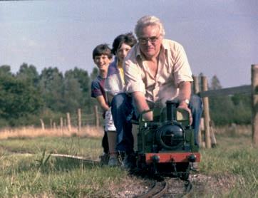
that, prior to retirement and presumably subsequent to shepherding, Bill had been a toolmaker by trade but had you the opportunity to examine his engine and with no prior knowledge of the fact, you would still have assumed it beyond any doubt; for Bill’s Dart was a Great Western tank locomotive built to a Rolls Royce standard With four big driving wheels to soak up the laps and a boiler that would have steamed freely on boiled cabbage - and especially when its builder was grinning cheekily at the helm - Bill’s Dart went like the absolute clappers (photo 74)
Shortly thereafter, Geoff - steam engine guru, boiler
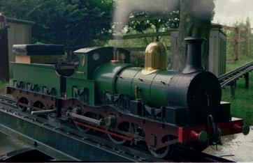
which he hoped to one day build too - but other than that and not being familiar with Great Central locomotives, I really did not know what to expect However, given Geoff’s superb machining skills, I certainly expected something special and, as he rolled her gently onto the track that frst time, I was not disappointed for she was an absolute beauty! Named Lorna after Geoff’s lovely wife (which, let’s face it, is also a much nicer name than ‘Class 12A’), she was an insidecylinde red, outside framed, gracefully fly-cranked and elegantly tendered engine with a 2-4-0 wheel arrangement She was the very picture of late Victorian elegance (photo 75) Lorna was strong, reliable, good natured, even-tempered and, when the queues were building and we were falling behind, it was always Lorna who helped to save the day Lorna was, in short, wonderful Oh and Geoff’s engine was a good
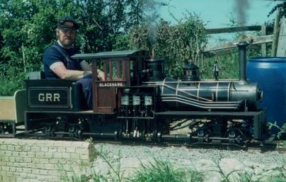
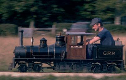
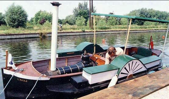
e l e g a n t w o o d e n c a b ( p h o t o s 7 7 a n d 7 8 ) A s b e f o r e , w h i l e i t w a s h e r s h e e r s i z e t h a t f i r s t d r e w a t t e n t i o n , i t w a s h e r s h e e r q u a l i t y t h a t r e t a i n e d i t F r o m a b u s y r a i l w a y o p e r a t o r ’ s p e r s p e c t i v e , P e t e ’ s S h a y w a s a l s o a g o d s e n d ; c o m f o r t a b l e a n d e a s y t o d r i v e , m a s s i v e l y p o w e r f u l a n d t o t a l l y r e l i a b l e – w h a t m o r e c o u l d y o u p o s s i b l y w a n t i n a 7 ¼ i n c h g a u g e e n g i n e ? W e l l , a s i t h a p p e n e d , P e t e d i d w a n t m o r e b e c a u s e , n o t o n l y c o u l d t h e b o g i e s o f P e t e ’ s e n g i n e b e c l e v e r l y c o n v e r t e d t o 5 - i n c h g a u g e f o r u s e o n o t h e r t r a c k s b u t w i t h t h e b o g i e s a n d c a b r e m o v e d , B l a c k h a w k a l s o f o r m e d t h e p o w e r p l a n t f o r P e t e ’ s p e r s o n a l p a d d l e s t e a m e r i n w h i c h h e t o u r e d t h e c a n a l s o f E u r o p e f o r s e v e r a l w e e k s e a c h s u m m e r ( p h o t o 7 9 ) . Y e s ! I k i d y o u n o t ! P e t e ’ s S h a y t u r n e d i n t o a b o a t i n i t s s p a r e t i m e H o w ’ s t h a t f o r c l e v e r ?
Postscript to Par t 13
For more pictures and information about Pete’s Shay in its paddle steamer guise, the QR code should take you to the appropriate place within the Steamboat Association of Great Britain’s website
p a i n t w o r k w i t h g o l d l i n i n g a n d p r o u d l y b e a r i n g t h e n a m e
B l a c k h a w k o n e a c h s i d e o f h e r
www steamboat org uk/user php?id=61653

inspector, dyed-in-the-wool Great Central Railway fan and occasional footplateman on the North Norfolk Railwayfnished the project he had been working on for many years and declared her ft for duty Now, while Geoff and I had discussed my Rob Roy many times over the years, for, like Bob, Geoff was someone to whom I turned when in need of sage cou nsel and friendly support in matters locomotive, his GCR Class 12A, also in 7¼ inch gauge, remained somewhat a mystery to me I knew that he had designed her himself and I understood she was a tender engine - and believed that he had also designed a tank engine variant ME
612 Model Engineer 5 May 2023
un
(
A n d f i n a l l y a n d w i t h m u c h a n t i c i p a t i o n , c a m e P e t e a n d h i s S h a y , n o w c o m p l e t e a n d r e s p l e n d e n t i n b l a c k
’
too
photo 76)
Bill, Dart and a train of laughing passengers as usual
Lorna at front, Lorna at rear and Geoff and a friend in between
Geoff and Blackhawk awaiting entry into the station.
Blackhawk in paddle steamer guise, touring Europe’s inland waterways. (Photo credit: Keith Broomfeld / The Steamboat Association of Great Britain )
Pete and his Shay at speed on the uphill straight.
74 75
Lorna, Geoff’s elegant GCR Class 12A, simmers gently on the turntable in later years. Her nameplates are missing that day, for reasons unknown
76 78 79 77
A F i v e - I n c h G a u g e 0-4-0 Padarn Railway Tender Locomotive
Luker builds a fi e inch gauge model o a elsh slate arr locomoti e
Continued from p 572,
M E 4715 April 21

P A R T 4
The rods in general T h e r e i s a l i t t l e d e v i a t i o n f r o m t h e o r i g i n a l w h e n i t c o m e s t o t h e c o u p l i n g a n d c o n n e c t i n g r o d s f o r t h e m o d e l ( f i g 6 ) T h e c o u p l i n g r o d s a r e v e r y l o n g a n d s l e n d e r a n d w o u l d n o t h a v e s u r v i v e d v e r y l o n g o n o u r t r a c k s o t h e y w e r e b e e f e d u p a f r a c t i o n T h e s a m e w a s d o n e f o r t h e c o n n e c t i n g r o d s b u t t h i s w a s m o r e t o g e t p r o p e r b e a r i n g s u r f a c e s a t t h e e n d s T h e a d d i t i o n a l m a t e r i a l i s v e r y s u b t l e a n d o u t o f p l a n e w h e n v i e w e d f r o m t h e s i d e s o t h e
m o d e l w i l l l o o k v e r y m u c h l i k e a p e r f e c t m i n i a t u r e
The manufacturing of the rods does require a certain amount of accuracy The coupling rods will be used to ft the frames to the boiler so they need to match each other and should be close to drawing to get the smokebox in the correct position The connecting rods need to be correct for the ftment of the cylinders, and although a little deviation here won’t be too catastrophic, too much will eat away the design allowance for the piston
drift due to the suspension movement of the driving wheel
The connecting rods
One of the things I wanted to mimic in the model is the prominent use of gluts and cotters at the big and small ends I’m not a fan of making these functional at this scale but if it fools the discerning rail expert I would consider my job done he general profles of the ends of the connecting rod were laser cut leaving out the oiling cylinders which would be soldered on at a later
M3 r5 3 Ø10 Ø5 1 5 M2 M2 5 205 4 150 215 4 1 2 8 7 3 6 1 1 4 3 1 1 3 Conrods 2 2 3 2 7 1 Big End Glut Big End Cotter Mat’l: 1mm BMS Note: 1 5mm tailstock offset for taper on connecting rods 4 5 2 1 3 4 2° 3° 0 6 1 8 2 Small End Glut Small End Cotter 3 4 3 6 2 6 3 0 6 5 3 2 Big End Detail Small End Detail 4 6 11 20 5 6 3 M3 M5 3° 2 5 AF from annealed Allen keys 7 3 Ø10 Ø13 5 Ø12 8 Small End Bearing Mat’l: Bearing bronze 0 3 4 3 Ø5 Ø8 7 3 A F 2 5 3 5 5 5 Common Oil Cap Mat l: Brass Ø4 6 M3 Ø1 2 8 4 1 3 1 7 6 Coupling Rod Cotter Coupling Rod Bearing Mat’l: Bearing bronze 4 3 r15 Ø1 Ø8 reamed 19 7 Cotter cutout cut on assembly M2 M3 6 7 . 2 1 0 8 2 r o u n d e d 2 2 4 Section R-R Q Q Section Q-Q Coupling Rods R R 5 6 7 M2 3mm AF 382 3
6
613 F I R E Q U E E N www.model-engineer.co.uk >>
Fig
Connecting and coupling rods
stage A slitting saw on the milling machine is the best way to make a very neat slot Unfortunately the smaller slitting disks seemed to be unavailable when I started this section of the build, and waiting patiently is not in my proverbial box of
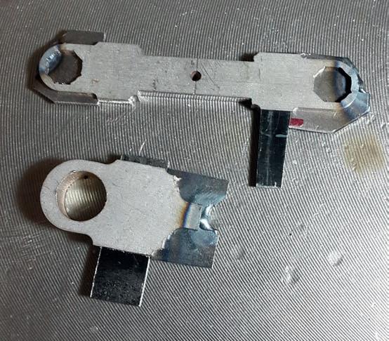
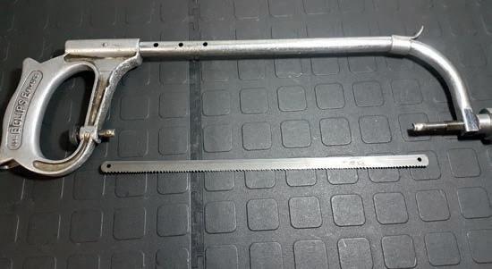
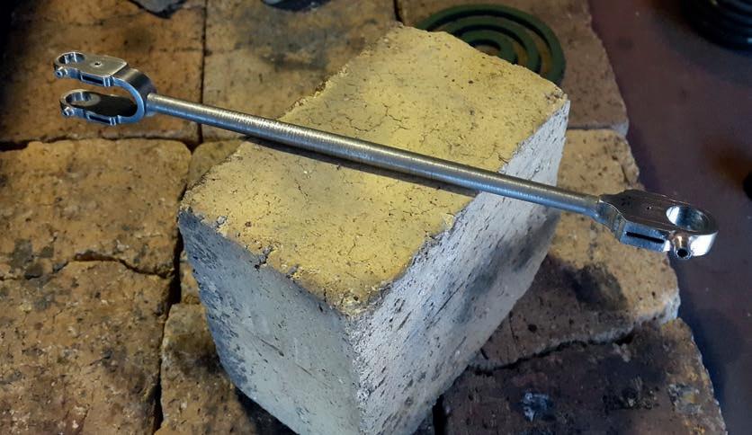
tricks! An alternative is to use a simple hack saw but keeping the cut exactly true is reserved for the true masters; even the old hack of using the top of the vice is tricky for a slot like this. n a side note, I haven’t bought hacksaw blades since
an orphaned band-saw found a place in my little workshop
If the blade is worn to a point it won’t cut without excessive downward force (which results in the band slipping off constantly , it gets chopped up and used as hacksaw blades.

sharp drill, with cutting fluid, properly clamped down between some wood will go through easily (photo 30)
To cut the slots for the cotters a simple sawing guide is made by milling a cavity (slightly undersized) with a little side clearance for the blade
The slot is then cut carefully with the lot clamped in the vice (photo 31) To get all the slots
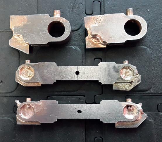
identical, a taper jig was ftted inside the slot and some 1mm plate pushed up frmly against the jig (photo 32) The end was tack welded (using TIG) to keep it in place for soldering, with liberal Tippex in areas where silver solder was not wanted (photo 33). The oil cups are simple lathe turning operations screwed into tapped holes prior to soldering the lot together If soldered properly, a decent fllet will form around all joints giving a very prototypical look After cleaning up the big and small ends the pilot hole for the octagonal small end bearing (photo 34) can be drilled mm , and the middle
33
The ends of the slots were soldered closed leaving the wedge hole open
30
Most of my hacksaw blades are made from the bandsaw blades when the number of joints becomes ridiculous
31
Slitting the back of the rods for the wedges using a simple jig and those bandhacksaw blades
32 614 Model Engineer 5 May 2023
To get all the slots uniform a taper jig was ftted inside the slot as a stop guide
section thinned using the sides of an end mill (photo 35 he drift, for opening up the octagonal bearing, is made from some silver steel quenched and tempered the normal way The octagonilism (sic) of the drift and the bearings themselves isn’t that important, in fact it’s benefcial to have some deviation for the press ft I used the graduations of my swivel vice to machine the sides with the pilot end a convenient stop guide The end of the octago nal is then undercut with a thin parting off tool to improve the cutting action (photo 35)
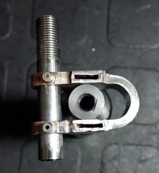
The small end strap is formed around a suitable mandrel in a vice with a little brute strength An 8mm bar should ft through both bearing cut-outs before the bearings are pressed home (photo 36)

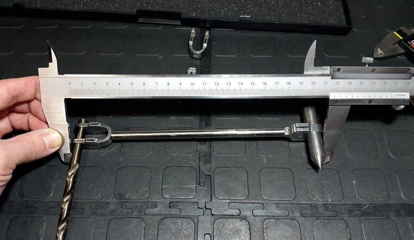
T h e c e n t r e t a p e r e d b e a m i s w h e r e a l l t h e t o l e r a n c e n e e d s t o b e t a k e n u p , w i t h t h e d i s t a n c e b e t w e e n t h e b e a r i n g c e n t r e s t h e c r i t i c a l l e n g t h ( p h o t o 3 7 ) I ’ v e a d d e d a c o n v e n i e n t d i m e n s i o n f o r c h e c k i n g t h i s d i m e n s i o n w i t h s u i t a b l y s i z e d p i e c e s o f r o d s s l i p p e d i n p l a c e T h e e n d s o f t h e r o d a r e s k i m m e d u n t i l t h e c o n n e c t i n g r o d i s o n s i z e F i n a l l y t h e r o d i s t a p e r e d b e t w e e n c e n t r e s a n d
t h e l o t i s s o l d e r e d m a k i n g s u r e t h e b e a r i n g s a r e p a r a l l e l ( p h o t o 3 8 ) . A l l t h e b e a r i n g s c a n b e m a d e f r o m p h o s p h o r b r o n z e o r b e a r i n g b r o n z e a n d p r e s s e d h o m e
The coupling rods
The coupling rods can be laser cut with the cutting marks cleaned up and the mid-section corners rounded from the centre of the link to the ends, gradually increasing towards the centre. The bearings are simple milling operations with the slot of the bearing and the slot for the taper wedge cut as an assembly The closing of the back end of the slot is the same as the connecting rod

The distance between bearing hole centres is important but more so that both sides are identical The rest of the bits and pieces require little description and are simple run of the mill operations
I’m fortunate enough to have a simple tin plating set-up which I use to hide all the silver solder and give the links a uniform look This is particular handy to prevent corrosion if the locomotives are used on a
wet track which is sometimes the case here A rainy day doesn’t dampen (sic) the spirits when it comes to a chance to steam up!
The smokebox
The shell of the smokebox (the drawings will be given a little later in the series) is needed to fx the distance between the two sub-frames (now that’s something you won’t read too often when following
36
The small ends bent around a former with an mm bar still ftting through the bearing holes
37
Checking the between centres length of the rod All adjustment is done on the tapered centre beam
Octagonal small end bearings being milled using a swivel vice with an 8mm guide for machining.
34 35 615 F I R E Q U E E N www.model-engineer.co.uk >>
The octagonal drift with the two small ends machined and bent into shape (note the thinning of the bent section)
Soldering the connecting rod assembly, no fewer than six soldered components.
a locomotive construction series hankfully, after this we have enough to start assembling the locomotive so some resemblance of a locomotive can start taking form on the stand
The shell itself is a welded construction although if you’re a sucker for punishment a riveted assembly like the prototype is possible I prefer TIG welding but I have heard of builders getting horrible porosity when welding hot
rolled plate using TIG. The trick is to clean all the scale off (which I do by leaving the parts in my pickling solution) which is essentially an oxide, just waiting to dissociate and gas up the weld
nce the shell is fabricated, the holes for the exhaust, blower and boiler fastening can be marked off and drilled As a side note, for any hole larger than plate thickness a standard drill will give a poor hole; normally it won’t be anything
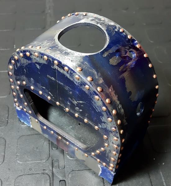
close to resembling a round hole Special stepped plate drills, which are my personal preference, are available at reasonable prices but failing this, a standard drill can be reground for plate-work

For the fake rivets I used normal household electrical copper wire; the 1 8mm variety
Blind holes, plate depth, were drilled and the rivets were formed the normal way using a hand punch former (photo 39) The actual Fire Queen had the exhaust pipes entering the smokebox at different points, with the left and right cylinders differing slightly I could see
no conceivable reason for this as the left and right side of this locomotive are identical other than the blower line which is nowhere near the exhaust My guess is the cylinders were either machined differently or the patterns were not perfect mirrors, and this was the end result. The model is of course symmetrical
The blast nozzle stand will be rigidly fxed to the smokebox base plate The mounting hole can be marked off, drilled and countersunk to drawing but when drilling the fxing holes to the sides of the smokebox the base plate should align the stand to the stack cut-out A close ftting bar with the centre drilled and tapped will aid as a holding jig and make sure the stand will be concentric and parallel to the stack (photo 40).
Assembling the frames and smokebox to the boiler
All experienced builders know that for any coupled wheel set on a locomotive the wheel axle centreline distance needs to match the coupling rod bearing centreline distance Of course all the crank pins’ off-sets need to be identical and the pins parallel, but we are not there yet. This locomotive is a cornucopia of tolerance stack up, with split frames connected to a fabricated boiler through a
40
Aligning the stack hole to the exhaust stand mounting hole on the base plate to make sure the blast nozzle is centre and parallel to the stack
39 38
The smokebo shell welded, drilled with all the fake rivets ftted into their blind holes
616 Model Engineer 5 May 2023
smokebox, not to mention the differential thermal expansion All this needs to be taken up somehow; the following is how I dealt with the tolerance stack-up by moving all the manufacturing deviation to the smokebox assembly ftment. If the coupling rods can be assembled back to back through the bearings with a little silver steel then you know the centreline distance is very similar, in fact perfect within model engineering tolerances That is half the job done
already, and the assembly is easy from there (fig 7)
At this point all of the machining tolerance is taken up by the fnal resting position of the smokebox on the boiler barrel but what of the thermal expansion? The expansion is very small for this boiler and luckily for us, is principally in one direction
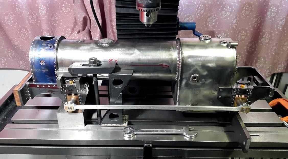
If the front and back frame are pushed together all the play is moved to the expansion side and our assembly is good to go All that’s left is to make
sure the axles are parallel (or alternatively, the bottom of the frames are all parallel , then the boiler can be drilled and tapped through the smokebox holes fter drilling and tapping, each hole should be ftted with a CSK screw to make sure the next hole doesn’t pull things in another direction.
You’ll notice in the picture I clamped the frame down; this was done very lightly just to make sure nothing moved when drilling (photo 41) With the four holes drilled at the top of
the smokebox, and the screws ftted, the smokebox is fxed and the three screws at the bottom can be drilled with the assembly moved for easier access
To the stand!
The locomotive is starting to take on a form more conducive to improving the Happiness Index It’s very disconcerting not seeing a project taking form on a stand But we’re getting there To
If the front & back frame are pushed together all play is moved to the expansion side & our assembly is good to go
The front sub-frame can be assembled to the smokebox shell & all the holes drilled & tapped
Finally all these sub-frames are assembled to the boiler with the coupling rods assembled to the wheel axle shafts where the ends are machined for a non-rattle fit to the coupling link bearing holes If you make the shafts longer for this stub they can be cut off & used as the wheel shafts after this setup
The back sub-frame should be assembled to the boiler with the side screws drilled & fastened
Attaching the sub-frames to the boiler
Fig 7
41 617 F I R E Q U E E N www.model-engineer.co.uk
Assembling the frames to the boiler using the side rods
be continued
A G r a s s h o p p e r B e a m E n g i n e
Martin Gearing presents an ideal beginner’s project with great potential for the more experienced builder
Continued from p 575
M E 4715 April 21
All dimensions are in mm Tolerance for all par ts in the ar ticleunless otherwise stated Non-functional (i.e. par ts that do not ft all match) ±0.1mm Functional (i.e. par ts having to match) ±0.02mm

Final assembly and valve setting
Refer to the three views (fig 1, 2 and 3) given in part 2 (M E 4699, September 9, 2022)
Notes:
* Each part should be lubricated sparingly with a trace of light lubricant as it’s assembled to another
* After each part is secured it should be checked for freedom of movement, whether it be sliding or rotation
* If any stiffness is detected the reason should be found and rectifed before continuing.
* Following these points is essential if ANY mechanical item constructed of multiple parts is to stand a chance of running smoothly after assembly
Some of the fxings required will need their overall length reducing as they are not ‘standard sizes’ Also, with regard to setscrews, it is often cheaper to purchase
the longest (threaded for the full length) setscrew available and cut to size rather than purchase every si e required if you are not a commercial operation For the fxings described the following abbreviations have been used:
SHCS – Socket Head Cap Screw CS Hd – Countersunk Head (USA Flat Head)
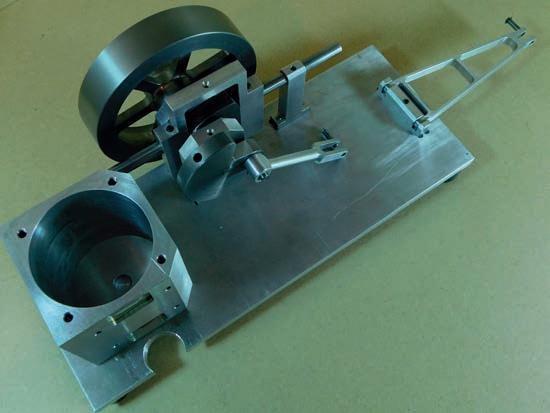
You may have been assembling the parts up as you made them as they were ordered to make that possible If not, though, the obvious place to start is with the base, which should have the cylinder block (item 16) already mounted four x S Hd It goes without saying that the bottoms of all the pockets milled into the base must be
618 Model Engineer 5 May 2023
Checking the cam follower bearing alignment
P A R T 19
129
free of any burrs left by the drilling of holes
* The four feet (item 48) should now be secured to the base, four x S Hd set screws - the same as used for the cylinder block).
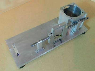
* The cam follower key (item may next be installed in its pocket and secured, x CS Hd set screws)
The cam follower shafts should have been checked that they were in line and running true, as discussed when they were assembled to the cam follower frame
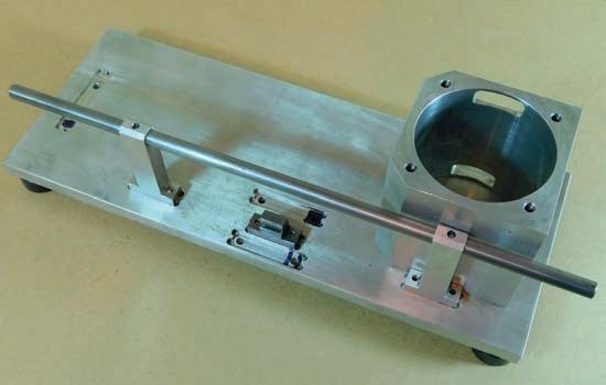
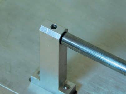
* Two cam follower bearings (item 3) should be checked to make sure that when they are bolted down the Ø8 reamed holes are in line
This may be done by sliding the bearings on a length of Ø8 silver steel rod with burr free ends and securing the bearings in their pockets x S Hd Set
two in each), and confrming that the rod is able to move freely ( ) If any stiffness is found there is a good chance that by changing the bearing’s orientation and/ or swapping ends may solve the problem If not then you need to check to see where the error lies This may be done by sliding the rod through one bearing and seeing in which direction the misalignment lies just before it enters the second bearing The process is then repeated the other way around Any misalignment may require one or both of the bearings to be ‘adjusted’, which
may take the form of either cutting a shim to ft between the bearing and the pocket base or removing, by the careful use of a fle, a little metal from the base of a bearing, if the centre distance is in error, or very carefully bending/twisting the upright section as required, until any misalignment is overcome ( ) Once the rod moves freely, mark the bearings to identify their orientation with the base pocket
* S l i d e t h e b e a r i n g s o n t o t h e c a m f o l l o w e r a s s e m b l y , b e f o r e d r o p p i n g o n t o t h e k e y / b a s e p o c k e t s a n d s e c u r e f o u r x S H d)
* Screw the two control valve stop pins (item 45) into the control valve spool retainer item and after ftting a BS 211 ‘O’ ring over the Ø29 stub of the control valve (item 42) pass the stub of the spool through the retainer and screw the control valve handle (item 44) into the spool Fit this sub-assembly
into the control valve body and locate hand-tight only four x round or button head set screws Finally ft the vacuum hose adaptor over the hose adaptor and secure to the control valve body, four x HSS).
* Attach the end link (item 25) to the end link pivot block item by ftting the end link pivot pin (item 27) taking care that the x grub screw
‘lands’ on the flat in the centre of the pin before tightening Fit an ‘E’ clip to one end of the end link/beam pin (item 28) and locate in one leg of the clevis ( )
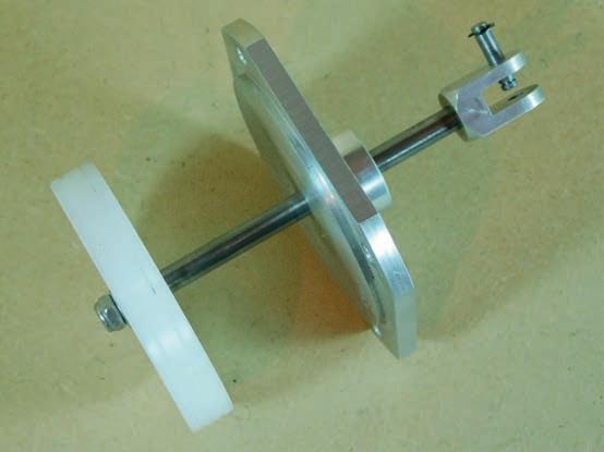
* Pass the piston/piston rod assembly (items 18 and 19) through the cylinder cover item and ft the piston rod clevis (item 20) applying a small drop of thread lock if available ( )
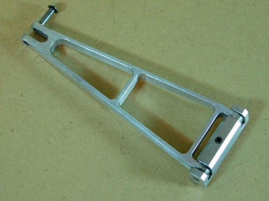
* F i t b o t h m a i n b e a r i n g c a r r i e r
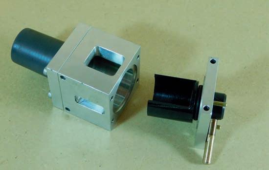
619 G R A S S H O P P E R g >>
Assembling the end link
The piston rod is passed through the cover and attached to the piston
Assembling the control valve
Slight misalignment of the cam follower bearings
Assembling the cam follower
–
130 134 132 131 133
a s s e m b l i e s ( i t e m s 2 a n d 6 ) w i t h t h e l a r g e r b u s h d i a m e t e r f a c i n g o u t w a r d s i n t o t h e i r p o c k e t s a n d s e c u r e t w o x S H d e a c h ) C h e c k t h a t t h e t w o
Ø 8 r e a m e d h o l e s a r e i n l i n e b y s l i d i n g t h e c r a n k s h a f t a s s e m b l y ( i t e m s 1 0 , 1 1 a n d

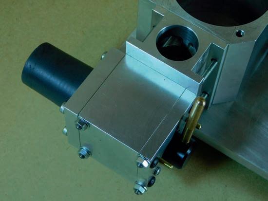
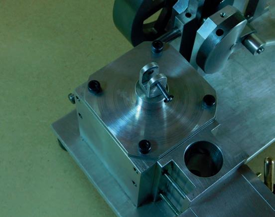

1 2 ) i n t o t h e b e a r i n g s I f a n y s t i f f n e s s i s f o u n d t h i s m a y b e r e m o v e d b y p a s s i n g a n Ø 8 r e a m e r t h r o u g h o n e b e a r i n g b u s h a n d r o t a t i n g i t a s i t e n t e r s t h e s e c o n d b e a r i n g b u s h T h e p r o c e s s i s t h e n r e p e a t e d t h e o t h e r w a y a r o u n d O n c e t h e s h a f t r o t a t e s f r e e l y , m a r k t h e b e a r i n g c a r r i e r s t o i d e n t i f y t h e i r o r i e n t a t i o n w i t h t h e i r b a s e p o c k e t S l a c k e n t h e t w o s e c u r i n g s c r e w s o n t h e i n n e r b e a r i n g a n d r e m o v e t h e o u t e r b e a r i n g F i t t h e
c r a n k s h a f t t h r o u g h t h e i n n e r m a i n b e a r i n g c a r r i e r a n d c a m f r a m e b e f o r e s l i d i n g t h e v a l v e c a m ( i t e m 1 3 ) ‘ b o s s ’ f r s t o n t o t h e c r a n k s h a f t f o l l o w e d b y t h e s e c o n d m a i n b e a r i n g c a r r i e r a s s e m b l y . ‘ S e t t l e ’ b o t h m a i n b e a r i n g c a r r i e r s i n t o t h e i r p o c k e t s a n d s e c u r e ( )
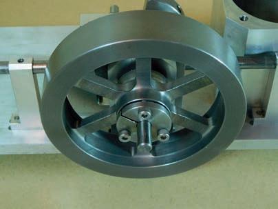
* F i t t h e f l y w h e e l c o l l e t i n t o t h e f l y w h e e l a n d s t a r t t h e t h r e e x c a p h e a d s e t s c r e w s b u t d o n o t t i g h t e n S l i d e t h e f l y w h e e l / c o l l e t o n t o t h e c r a n k s h a f t ( 1 3 6 ) p o s i t i o n i n g i t s o t h a t t h e r e i s a b o u t 0 . 1 ( a v e r a g e p a p e r t h i c k n e s s ) c l e a r a n c e i n t h e f o r m o f e n d f l o a t
b e t w e e n t h e i n n e r f a c e s o f c r a n k w e b / c o l l e t a n d o u t e r f a c e s o f t h e m a i n b e a r i n g b u s h e s T u r n e a c h b o l t a l i t t l e a t a t i m e , g o i n g r o u n d s e v e r a l t i m e s u n t i l a l l t h r e e a r e t i g h t t o e n s u r e t h e c o l l e t i s ‘ s e t t l e d ’ i n t o t h e f l y w h e e l t a p e r w i t h a n e v e n t e n s i o n o n a l l t h r e e b o l t s
620 Model Engineer 5 May 2023
The crankshaft is ftted to the main bearings
Attaching the ywheel to the crankshaft
Assembling the connecting rod to the crank
The cylinder block cover is secured to the cylinder block
The valve block and control valve are attached to the cylinder block
138 140 136 139 135 137
Assembling the valve link and lever to the beam


