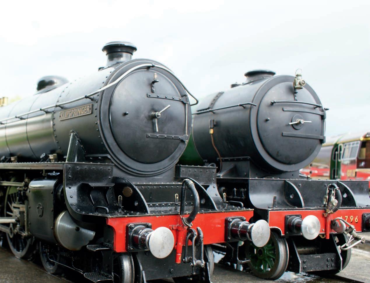









❖❖ THE ORIGINAL MAGAZINE FOR MODEL ENGINEERS Vol. 230 No. 4714 • 7 April –20 April 2023 Join our online community www.model-engineer.co.uk SLOTTING An attachment for the lathe Fire Queen Slate quarry loco A4 Build We check on progress with a 7 ¼ inch gauge A4 Pacific build Gornergrat We take a trip on the first electric mountain railway

Published by Mor tons Media Group Ltd, Media Centre, Morton Way, Horncastle, Lincs LN9 6JR Tel: 01507 529589 Fax: 01507 371066

© 2023 Mor tons Media ISSN 0026-7325


www model-engineer co uk


EDITORIAL
Editor: Mar tin R Evans
Deputy editor: Diane Carney
Designer: Druck Media Pvt Ltd
Club News: Geoff Theasby
Illustrator: Grahame Chambers
Publisher: Steve O’Hara
CUSTOMER SERVICES
General Queries and Back Issues
01507 529529

Monday-Friday: 8 30am-5pm
Answerphone 24hr
help@classicmagazines co uk
www classicmagazines co uk

ADVERTISING
Group adver tising manager: Sue Keily
Adver tising: Angela Price
aprice@mor tons co uk Tel: 01507 529411

Ad production: Andy Tompkins
By post: Model Engineer adver tising, Mor tons Media
Group, Media Centre, Mor ton Way, Horncastle, Lincs LN9 6JR
PUBLISHING
Sales and distribution manager: Carl Smith
Marketing manager: Charlotte Park
Commercial director: Nigel Hole
Publishing director: Dan Savage
SUBSCRIPTION
Full subscription rates (but see page 486 for offer): (12 months, 26 issues, inc post and packing) –
UK £128 70 Expor t rates are also available, UK subscriptions are zero-rated for the purposes of Value Added Tax
Enquiries: subscriptions@mor tons co uk

PRINT AND DISTRIBUTIONS
Printed by: Acorn Web Offset Ltd , W Yorkshire
Distribution by: Seymour Distribution Limited, 2 East Poultry Avenue, London EC1A 9PT
EDITORIAL CONTRIBUTION

Accepted photographs and articles will be paid for upon publication Items we cannot use will be returned if accompanied by a stamped addressed envelope and recorded delivery must clearly state so and enclose sufficient postage In common with practice on other periodicals, all material is sent or returned at the contributor’s own risk and neither Model Engineer, the editor, the staff nor Mortons Media Ltd can be held responsible for loss or damage, howsoever caused The opinions expressed in Model Engineer are not necessarily those of the editor or staff This periodical must not, without the written consent of the publishers first being given, be lent, sold, hired out or otherwise disposed of in a mutilated condition or in other unauthorised cover by way of trade or annexed to or as part of any publication or advertising, literary or pictorial manner whatsoever
488 SMOKE RINGS
News, views and comment on the world of model engineering
489 LNER B1 LOCOMOTIVE
Doug Hewson presents a true to scale 5 inch model of Thompson’s B1
494 AN ENGINEER’S DAY OUT
Roger Backhouse admires the Matterhorn from the comfor t of the world’s first electric mountain railway
499 THE EATING OF ELEPHANTS
Steve Goodbody argues that anything is possible if you take it a bite at a time
502 A FIVE-INCH GAUGE 0-4PADARN RAILWAY TENDER LOCOMOTIVE
Luker presents Fire Queen, a Welsh slate quarry locomotive
508 GRASSHOPPER BEAM ENGINE
Mar tin Gearing describes a half beam engine suitable for a beginner
512 A4 PACIFIC CONSTRUCTION
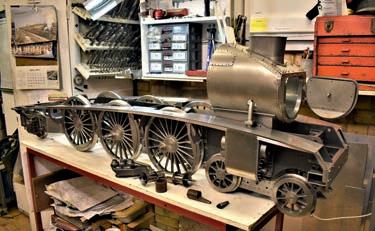
John Arrowsmith visits a workshop where an impressive 7¼ inch gauge A4 is taking shape

516 FITTING DIGITAL READ OUTS TO A WARCO
Graham Astbury explains how he fitted the scales to a Warco WM16 milling machine
SUBSCRIBE & SAVE UP TO 49%
See page 306 for details
520 FLYING SCOTSMAN IN 5 INCH GAUGE
Peter Seymour-Howell builds a highly detailed Scotsman based on Don Young’s drawings
524 POSTBAG


Readers’ letters
526 SLOTTING ON THE LATHE
Jacques Maurel investigates the forces involved in creating slots on a small lathe
530 COMPLETING BRIDGET
Jon Edney concludes the construction of his first locomotive
534 CLUB NEWS
Geoff Theasby compiles the latest from model engineering clubs around the world
537 C L U B D I A RY
Future events
http://www facebook com/modelengineersworkshop


http://twitter com/ modelengineers

230 No. 4714 7 April – 20 April 2023 530 512
Vol.
www.model-engineer.co.uk
. . .
O N T H E C O V E R
This issue was published on April 7, 2023 The next will be on sale on April 21, 2023 ❖❖ THE OR G NAL MAGAZINE FOR MODEL ENG NEERS –Jo n o r on ne ommunity www mo e -e g nee co uk S LO T T I N G An t hmen fo the he Fire Queen S a e quarry oco A4 Build We check on prog ess with a 7¼ nch gauge A4 Pac f c bui d Gornergrat We take a tr p on he fi st e ectr c mounta n a way
Two five inch gauge locomotives –a B1 by Brian Apthorpe and a V2 by Peter Layfield (photo: Doug Hewson)
483 www.model-engineer.co.uk
499













P R I N T O N LY Q u a r t e r l y d i r e c t d e b i t fo r £18.00 1 ye a r d i r e c t d e b i t fo r £65.00 1 ye a r c r e d i t / d e b i t c a r d fo r £70.00 P R I NT + D I G ITA L Q u a r t e r l y d i r e c t d e b i t fo r £21.00* 1 ye a r d i r e c t d e b i t fo r £82.99* 1 ye a r c r e d i t / d e b i t c a r d fo r £84.99* D I G I TA L O N LY 1 ye a r d i r e c t d e b i t fo r £49.00* 1 ye a r c r e d i t / d e b i t c a r d fo r £52.95* *Any digital subscription package includes access to the online archive Enjoy 12 months for just £65 GREAT REASONS TO SUBSCRIBE > Free UK deliver y to your door or instant download to your device > Great Savings on the shop price > Never miss an issue > Receive your issue before it goes on sale in the shop SUBSCRIBE AND SAVE L MAGAZINE FOR MODEL ENGINEERS V 9 N 70 4 - 1 m ou online community www m del-enginee c uk EDERATION AGM d Autumn Rally at Little Hay Midlands Show First impressions ❖❖ THE ORIGINAL MAGAZINE FOR M V 3 4 11 J n our n ne c mmu SCOT IMLEC 2023 We invite entries for this year s efficiency compeition We visit a bobb ❖❖ THE ORIGINAL MAGAZINE FOR MODEL ENGINEERS 4712Jo n ou on ne commun ty mode -eng nee L i n co l n s h i r e L i n e Exploring the history of the Lincolnshire Coast Light Railway h u r c h the 150th the s EC 2023 rd to the small ficiency competit on We V t Rye d a l e We tak p Nor th Yorksh re SAVE 49%
w w w.classicmagazines.co.uk /MEDPS 01507 529529 and quote MEDPS Lines open Monday to Friday 8 30am – 5 00pm GMT Offer ends December 31, 2023 Subscriptions will start with the next available issue Direct Debit payments will continue on the agreed plan unless you tell us otherwise To view the privacy policy for MMG Ltd (publisher of Model Engineer), please visit www mortons co uk/privacy Please visit www classicmagazines co uk/terms for full terms & conditions
Jaw Regrinding - Pete Barker
Mar tin Evans can be contacted on the mobile number or email below and would be delighted to receive your contributions, in the form of items of correspondence, comment or ar ticles.


07710-192953
MEeditor@mor tons co uk


Harrogate
As you read this it will be four weeks since I attended the new Harrogate exhibition although, as I write this, it is only a week ago My impression of the show is that it was a great success, despite the weather Model Engineer and Model Engineers’ Workshop had a stand at the show and it was good to meet many of you there I hope this show will become an annual fixture, giving us two nationwide shows each year (the other being the Midland Exhibition at The Fosse)
The show combined a model engineering exhibition with a model railway show which, of course, expanded the ‘catchment area’ considerably, as model railways are a far bigger hobby than ours There is the hope that many of the model railway fraternity will have taken a look to see what we get up to and
perhaps
we might have acquired a few converts
There were many very impressive models on show but one that stood out for me was Alan Crossfield’s latest project, a five-inch gauge GWR pannier tank, no 7713 There are two reasons for this; firstly, I am currently (and rather slowly) completing my own pannier tank and, secondly, the outstanding quality of the workmanship The model is complete and now requires painting but looks resplendent in brass and steel (photo 1) Look on my works ye mighty and despair was my first reaction, as it was for some others I spoke to, but it is a prime example to the rest of us of what it is possible to achieve

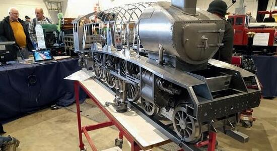
Another very impressive model was Tony Bickerstaffe’s 7¼ inch gauge A4 Pacific, which is in the course of construction (photo 2) You can read more about this model in John Arrowsmith’s ar ticle on page 512 in this issue John will also be repor ting on the show in our next issue

After the Harrogate show, I hot-footed it down to The Fosse to take a look at the Large Scale Model Railway show – ‘large’ being a relative
term here as their ‘large’ ends more or less where we star t One of the most interesting aspects of the show, for me, was the oppor tunity to admire a few Gauge Two models
There are few of these as this par ticular gauge only lasted for about 20 years in the early 20th century, so these models are generally about a century old (photo 3) The problem with Gauge Two is that it is wedged rather tightly between Gauges
One and Three (2½ inch gauge) and the manufacturers (principally Bassett-Lowke) felt they couldn’t suppor t so many gauges John Arrowsmith will also be writing about Gauge
Two in a future issue
Nostalgia Corner
I happened upon this locomotive on the Keighley
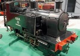
club stand (photo 4) and immediately recognised it as an engine I had ridden behind many times when I was a small boy, over 60 years ago I was brought up in Ilkley and our neighbour was a one-armed model engineer called Peter Walton, who built this five-inch gauge Y4 and ran it up and down a raised track in his large garden, occasionally offering rides to his neighbour ’s children!
Model Engineer 7 April 2023
DIANE CARNEY Assistant Editor
MARTIN EVANS Editor
Alan Crossfield’s newly completed five-inch gauge GWR pannier tank.
Tony Bickerstaffe’s 7¼ inch gauge A4 Pacific locomotive.
A century-old Gauge Two model seen at The Fosse.
Peter Walton’s five-inch gauge Y4 locomotive
–
–
488
1 2 3 4
L N E R B 1 L o c o m o t i v e
Doug Hewson presents an authentic 5 inch gauge version of Thompson’s B1 locomotive.


We now come to the bogie frame drawings (fgs 55 to 59) so not many photographs this time I am afraid I have managed to find one photograph which I could blow up enough to give a half decent view of the guard irons Photograph 109 is actually of a green B1 photographed at Per th and I was ver y pleased to see it has the proper front bogie on it! It is the type fitted to the ones I have drawn as being from 8301 to 8310 until withdrawal. It is folded at either end to b olt it to the side frames, and it has the double scallop at the top and bottom That was all the information I could find but I got this information from an ‘Isinglass’ drawing I must say that these LNER locomotive drawings are absolutely full of information and I bought the one which was printed out at 13 5mm to a foot so that is half si e for five-inch gauge so it was a ver y long drawing! Anyway, I have included an enormous amount of detail from these drawings Photograph 110 is just a p hotograph taken around the turntable at Gilling East which shows a lovely B1 Klipspringer, which was laboriously rebuilt

1 1 1 / 1 6 1 1 / 2 1 5 / 1 6
LNER B1 61002 at Perth
Fig 55
Bogie long cross-section
110 489 www.model-engineer.co.uk >>
Five inch gauge B1 and V2 at Gilling
P A R T 17 – F R O N T B O G I E F R A
E S
M
109
Continued from p 471, M E 4713, March 24
from a very old Martin Evans B1 by Brian Apthorpe, and it does now look very much like a B1 Alongside it is Peter Layfield’s and it looks as though it has just returned to the shed having been on a ‘Class F Through Goods Train’ judging by the head lamp code and just visible behind that is Tim Coles’s GT3. This provides a nice view of the guard irons on Brian’s B1

Photograph 111 - now, if you need any fire irons there is a very nice selection in this picture! It is 61037 surrounded by fire irons and just visible in the bottom of the picture is a lifting bar and there are several clinker shovels round about Leaning against the lamp post is a baffle plate, along with a couple lying on the ground and all manner of other items If your boiler has been built properly it should have a half round plate in the bottom of the fire hole ring which is shown on my drawing 10 in the full set The baffle plate sits on the top of the half ring inside the fire box Photograph 112 was photographed on 61153 in Canklow Roundhouse and shows a different type of bogie This one is the final type of bogie as shown on my drawing It is the fifth type as shown on the drawing I just had to show this photo (photo 113) which

56
LNER B1 61153 in Canklow Roundhouse
Fig
112 490 Model Engineer 7 April 2023 3/16 19/32 13/32 7/16 5/8 2 1/8 9/16 3/16 4 3/8 25/32 1/64 1 5/16 1 1/4 21/32 1/16 1/4 7/16 23/32 19/32 5/16 19/32 3/32 3/32 17/32 Wearing strip 5 / 8 1 1 / 8 7 / 1 6 5 / 1 6 3 / 3 2 3 / 3 2 5 / 3 2 1 / 1 6 1 9 / 3 2 1 9 / 3 2 7 / 8 7 / 8 2 5 / 8 5 2 5 / 3 2 1 / 1 6
LNER B1 61037 and assorted junk. (Photo by Rail Online.)
Bogie frame
111
is of the bogie on 6 0 and shows the fourth type of bogie It would just be very nice to know who these legs belong to but it looks very much he is topping up the oil boxes on the front axle boxes

Now, I didn’t want you to be short of a job for a couple of weeks so if you have not made the screw couplings and buffers for your B1, yet I thought that I would just pop the drawings in for you to be getting on with (fgs 60 and 61) You can buy the buffer stocks and the draw hooks from The Steam Workshop I am not sure whether or now Geoff also has them in stock at G & S Supplies but it is always worth a try
Note that when making the buffers the spring retaining plate is the same size as the flange on the buffer stock and is held on with four 10BA countersunk screws The spring will just need to compress a little so that it can’t rattle about in its housing Believe me, that you should not be able the press the buffer in with finger pressure The springs need to be ¼ inches long by inch diamete r and be made from 6swg wire If you are buffing up to a train, I can assure you that they will compress!
I have shown on one of the drawings a nice little mudguard (fg 62) and these can be flanged over a former the way I made mine for my BR -6-4 Tank These were of course made in one piece I have actually shown small angles to attach them to the frame plates!
I made the patterns for the screw coupling shackles which I always used to buy in stainless steel, being easier
to cast than mild steel, and you should also be able to buy those from one of the above named suppliers You will require a pair of gedge draw hooks, one pair of short
shackles with a gedge in those and one pair of long shackles without the gedges in them
I d o n ’ t k n o w w h e t h e r a n y o n e
i s g o i n g t o m a k e p a t t e r n s f o r
t h e b o g i e a x l e b o x e s ( f g 6 3 )
b u t i t w o u l d b e v e r y n i c e i f t h e y d i d - y o u w i l l n e e d t w o o f o n e h a n d a n d t w o o p p o s i t e h a n d o n e s S o m e o n e n e e d s t o m a k e a 3 D d r a w i n g o f t h e m
a n d w e c a n d o t h e r e s t T h e
Fig 57 113 491 L N E R B 1 www.model-engineer.co.uk 1 3 1 / 3 2 1 3 1 / 3 2 6 2 1 / 3 2 2 5 / 8 3/8 1 25/32 1 25/32 4 3/8 3/8 3/8 Side play Side play
Bogie plan view
LNER B1 61320 receives some TLC. (Photo by Rail Online.)
Fig 58
59
Fig
2 3/4 21/32 23/32 13/32 17/32 r11/32 r13/32 1/16 1/16 1 1/4 7/8 1 3/32 7/32 1 3/4 4 3/8 4 15/32 29/32 18SWG mounting plate for r5/8” ball 20SWG slipper plate r5/8 7/16 1 25/32 3/8 side play 3 7/16 1 5/16 1 1/32 1 1/2 1 1/2 3/8 1 11/16 5/16 7 / 1 6 3 / 1 6 1 / 1 6 1 / 4 1 1 / 1 6 2 7 / 3 2 9 / 3 2 1 / 8 3 / 3 2 2 3 / 4 1 / 1 6 1 5 / 1 6 1 1 1 / 1 6 2 1 / 3 2 5 / 3 2 1 1 / 3 2 3 / 1 6 9 / 3 2 2 1 / 3 2 5 / 3 2 3 / 3 2 1 / 4 5 / 3 2 1/8 Bogie stretcher 7 / 1 6 1 / 4 1 / 1 6 3 / 3 2 7/16 3/32 Guard Iron Mat’l: 16SWG M S 5/8 1 1/32 Allow for bending 1/4 21/64 3/4 Knuckle Nut BR Std. Screw Coupling Mat’l: Steel castings 1 5/16 r9/64 Ø3/8 Ø11/32 r9/64 5/16 11/16 9/32 3/32 Gedge formed in top link Collar pressed on & hole for tommy bar drilled afterwards 11/16 1/8 1 7 / 3 2 1 / 4 3 / 6 4 1 5 / 3 2 3 / 1 6 7 / 3 2 1 / 4 1 5 / 3 2 7 / 8 3 1 / 8 e x t e n d e d 7 / 8 3 B A s c r e w 7 / 3 2 3 / 1 6 4 Model Engineer 7 April 2023 Guard iron Screw coupling
Fig 60
Buffer heads and stocks
Mudguard Over Rear Wheel Of Bogie
Mat’l: Mild steel, LH shown
Bogie mudguard
d r a w i n g n e e d s a 4 % s h r i n k a g e a l l o w a n c e o n t h e m i f a n y o n e f a n c i e s h a v i n g a g o a t t h a t T h e r e s h o u l d b e a l o o s e k e e p t o g o w i t h t h e a x l e b o x a n d a p a s s a g e w a y f r o m t h e l i t t l e o i l b o x i n t o t h e u n d e r k e e p w h i c h s h o u l d t h e n b e p a c k e d w i t h a f e l t p a d I t s h o u l d a l s o b e fi t t e d w i t h a n i c e c l o s e - fi t t i n g l i d
To be continued
NEXT TIME
We finish off the bogie and move on to the locomotive brakes.
Bogie axlebox
Ø 3 / 8 Ø3/4 Ø 7 / 8 Ø 1 1 / 1 6 Ø 1 1 / 1 6 Ø 3 / 4 1 1 / 8 Ø 1 5 / 1 6 Ø 2 5 / 3 2 5/32 3/32 3/32 3/8 11/16 1/16 1 1/8 1 1/8 1/8 1/8 15/16 Thread 1/2 x 32 Buffer Heads Mat’l: M S Stocks Mat’l: Brass castings Cut 4 off 1/16” notches & make spanner to suit Drill 4 off no 43 holes for 8BA bolts Drill 4 off no 55 holes & tap 10BA 16SWG spring retaining plate Ø9/16 1 1/16 Tap 10BA for light cover Thrust pad Two Ø1/16 dowels Bogie Axlebox And Keep Mat l: G M Fill this cavity with felt pad or worsted wool 1 1 / 1 6 1 1 / 8 9 / 1 6 9 / 1 6 1 / 4 1 3 / 3 2 1 3 / 1 6 1 / 6 4 1 1/16 13/16 9/16 13/32 23/32 7/32 1/32 7/8
Fig 61
Fig
r 123/32 r127/32 r 1 7/8 1/2 13/16 3/16 1/2 1/4 5/8 15/16 3 / 1 6 5 / 3 2 1 21/32
Fig 62
63
493 L N E R B 1 www.model-engineer.co.uk
An Engineer’ s Day Out
T h r e e P h a s e t o t h e Pe a k s
t h e G o r n e r g r a t R a i l w a y, S w i t ze r l a n d
For this ar ticle Mr and Mrs Backhouse took their first ever package holiday to see an historic mountain railway, the Zermatt to Gornergrat rack railway which opened in 1898 Using the Abt rack system it was the first electrically powered mountain railway and used three phase electricity Still flourishing today it offers spectacular views of the Matterhorn and other peaks (photo 1).
British tourists discovered Switzerland in the 19th century; they enjoyed the scenery but complained about hotel quality and overcharging (Swiss hotels are now excellent but tourists still complain about Swiss prices ) Their holidays often involved mountain walking and climbing Even Queen Victoria ascended the Rigi, but on a pony
As railways and lake steamers developed, more tourists came - Thomas Cook brought his first party to Swit erland in 1863 - and local people saw business opportunities Inspired by America’s Mount Washington Cog Railway, Nicholas Riggenbach devised his own ladder-like rack and

cogwheel railway which opened up the Rigi in 1875. Other rack systems followed; Roman Abt devised a system with two racks with milled teeth, offset, and a double pinion on the locomotive (photo 2) First used in 1885, it is commonly utilised today including on the Snowdon Mountain Railway Edward Locher invented his system to ascend Mount Pilatus, still the steepest cogwheel railway, opened in 1889 That had two racks placed horizontally with cogwheels engaging on either side. The Strub system uses a single rack. These mountain rack railways were worked by steam power and were only later converted to electric operation, although the Brienz-Rothorn Bahn remains mostly steam worked with modern oil fired locomotives plus some diesels
Reaching Zermatt

Ironically, publicity surrounding dward Whymper’s first ascent

494 Model Engineer 7 April 2023
-
Roger Backhouse takes a trip on the world’s frst electrically powered mountain railway.
Gornergrat Station is at 3089 metres (10,132 feet) above sea level and has superb views of the Matterhorn, Monte Rosa and other peaks around Zermatt.
1
2
Abt rack system in place at Gornergrat station
At frst it operated summer only as winter sports had not then developed in the Zermatt area. Photo courtesy Matterhorn-Gotthard
and tragic descent of the Matterhorn in 1865 brought more visitors to Zermatt
Visitors still walked or rode up the Mattertal Valley but in 1888 work began on a line from Visp where it met standard gauge tracks The Bundesrat (Swiss Federal Council) insisted on metre gauge rather than the narrower gauge originally proposed


A special commission investigated possible systems and the Abt rack system was chosen By July 1891 the railway had reached Zermatt (photo 3) but operation remained summer only as Zermatt hotels did not open in winter until 1927/28


Large scale winter sport is a comparatively recent development in Switzerland

Like other Swiss lines the railway was steam operated at first (photo 4) but coal shortages and rising costs during the First World War encouraged interest in electrification (Swit erland has few and limited coal deposits). From October 1929 it was electrified using ,000 volts AC. This was chosen rather than the ,000 AC of the Federal Railways as transformers could be air rather than oil cooled and therefore lighter which is important on a steeply graded line
The route of the railway was susceptible to rockfalls and Valais Canton funded shelters from 1933 which enabled yearround operation Along this

495 E N G I N E E R ’ S D A Y O U T www.model-engineer.co.uk >>
The ‘Glacier Express’ takes a photostop at Nätschen on the Furka - Oberalp Railway It is claimed as the world’s slowest express.
The steel cantilever Findelbach bridge is the major engineering work on the Gornergrat line Original plans were for a stone arch viaduct The Matterhorn is partly hidden by clouds Photo courtesy Matterhorn-Gotthard Bahn 2022
Snowsheds became essential once winter sports developed Besides protecting the line from avalanches they also protect against rock falls
Early poster for the Gornergrat Railway
Bahn 2022.
An early photograph of Muehlebache Viaduct on the metre gauge line from Visp to Zermatt opened in 1891 Photo courtesy Matterhorn-Gotthard Bahn 2022
The Visp to Zermatt line was frst worked by rack locomotives This example was built by SLM of Winterthur Photo courtesy Matterhorn-Gotthard Bahn 2022
Matterhorn Gotthard Bahn train en route from Visp to Zermatt forming the last stretch of the ‘Glacier Express’ route from St Moritz Railways in such diffcult terrain require expensive maintenance
6 7 8 3 4 5 9
spectacular line, large scale works also provided protection against floods and avalanches
(photo 5)
Passengers changed at Visp for standard gauge trains but a metre gauge track was added in 0 enabling the first through ‘Glacier xpress’ to run from St Moritz to Visp


and Zermatt via the Rhaetian Railway and Furka-Oberalp lines (photo 6) This still operates today and ‘panoramic’ coaches afford spectacular views Some trains include dining cars and the jouney is marketed as a luxury travel experience, drawing visitors from around the world A party

of Americans were enjoying their meal during our trip. (More thrifty travellers should purchase provisions at one of the excellent local Co-ops before boarding )
Building the GornergratMonte Rosa Bahn

Plans for a mountain railway from Zermatt were initially opposed locally due to the expected effects on


employment of mountain guides and porters The Federal Government disregarded such fears as they had proved groundless in the Bernese Oberland so construction of the metre gauge GornergratMonte Rosa Bahn with Abt rack system began in 1898 by a private company
Like other Swiss Railways, much work was done by Italian labourers whose story
496 Model Engineer 7 April 2023
Gornergrat Station with siding Views are magnifcent - on the right is the Weisshorn (4506 metres) and then the Zinalrothorn (4221metres) The twin railcar dates from the 1960s and is one of the oldest in service
Twin-railcar 3051 One of four supplied by SLM in 1993
State of the art ‘Polaris’ twin railcar made by Stadler; one of fve introduced in autumn 2022
Zermatt station with crane wagon Maintenance of a mountain line all year round is a major task.
Above the summit hotel with the observatories and the Matterhorn On a good day views are truly magnifcent
10 11 12 13 14 15
Original locomotive pushing a ski train. Winter operations didn’t start until 1942. Note the special wagon for skis. Photo courtesy Matterhorn-Gotthard Bahn 2022.
is often overlooked Since the Gornergrat is at a high altitude and usually temperatures are low, most construction was limited to the summer season but even so, the performance of the workers was compromised due to the altitude However, there seems to have been greater care taken of the workforce than on other railway construction. (Thirty men died building the Jungfraujoch Railway ) A steam locomotive was used in construction and is now preserved in Spain
On the line’s 5¼ mile (8 5km) route there is one example of major civil engineering the 0 metre long Findelbach gorge bridge (photo 7) Originally intended as a stone viaduct with 48 metre (157 feet) high pillars the design was changed to a cantilevered steel design There are four tunnels and more recently snow sheds have been added to protect the line from avalanches, particularly in the higher parts of the line One snow shed is nearly half a mile long (792metres) In these mountains an avalanche may not be powdery snow but highly damaging, hard packed ice bringing rocks down (photo 8)
n 0 August the railway opened to Gornergrat
(photo 9) as the second electric mountain railway in the world (photo 10) By 0 the line had extended higher up the Gornergrat and a summit hotel opened soon after. The two astronomical observatories were added in the late 60s and subsequently used for a range of observations including solar neutron detection (photo 11)

Operation today
This is a slick and efficient railway employing over a hundred people and carrying nearly two million passengers a year Now part of the Matterhorn-Gotthard Bahn group the line can convey up to ,400 people an hour in each direction taking just 33 minutes for the journey As usual on mountain rack railways upward speeds (max 0kph) are higher than those descending ( 027kph) More modern stock is allowed a faster descent
The double track, metre gauge line rises from Zermatt at 60 metres above sea level (5265 feet) to Gornergrat at 0 metres ( 0, feet) with four intermed iate stations Average gradient is in ( 0 ) It is the second highest station in Europe and the highest in the open. (The Jungfraujoch line and stations are in tunnels )

At first trains operated with locomotives pushing the train (photo 12) but now railcars are used (photos 10 and 13) These have space and racks for skis Recently the line has taken delivery of state of the art Stadler ‘Polaris’ railcars (photo 14) Even a short mountain railway is difficult to maintain all year round so the railway has a number of works wagons including water tankers, a crane truck and wagons for materials (photo 15) Most spectacular are the two snow blowersthough few will see them in action They feature in an audiovisual presentation in Gornergrat summit buildings (photo 16)

Electric power
As in 1898, electricity for the line is still generated at a hydro-electric power station
497 E N G I N E E R ’ S D A Y O U T www.model-engineer.co.uk >>
Snow blower in operation on the Gornergrat Railway. A spectacular sight if you are fortunate enough to see it. Photo courtesy Matterhorn-Gotthard Bahn 2022.
Twin pantographs for the three phase electric supply
16 17 18
Ski lift terminus at Riffelberg Unfortunately the paraphernalia of winter sports can be a blot on the landscape though such transport helps the less ft reach peaks like Gornergrat
in Zermatt Trains use three phase electricity at 725 volts AC which explains the unusual two wire overhead and the double pantographs (photo 17) This system was chosen in 1898 following an evaluation of four different types of power supply
Three phase electricity means that since its opening, locomotives and railcars have been equipped for regenerative braking now using asynchronous motors Energy generated coming down is fed back to the overhead, enabling two downward trains to power at least one train going up, so avoiding energy consuming brakes
A typical three-phase power distribution system has three line phases and one neutral For a perfectly balanced three-


phase load (such as a train motor) the phases balance out and the neutral carries the zero current and can therefore be omitted At a local level the three-phase power is transformed down to a lower voltage, with the transformer secondary giving three outputs phase to phase
This is star connection as the three phases radiate out from the neutral point like a star, with each phase being 0 degrees apart from the next phase Neutral is connected to earth at the substation The voltage between each phase and the neutral is 419 volts which is 725 divided by the square root of three (1 73) As the neutral is earthed at the substation, each phase is always 419 volts above earth
The transformer has one phase connected to earth instead of the star point, so that running rails are earthed and the two overhead wires are connected to the other two phases The star point is not connected to anything other than one end of each of the three windings and therefore ‘floats’ at whatever voltage it is There is no neutral connected to the star as the load, being a motor, is always balanced, so there is no need for a neutral With three-phase, electricity power output from the motor is constant and for a rack railway, variable speed drives are not ne eded These are not fast lines The power is controlled using solid state electronics when starting up until it is running at full speed
Originally the line had wooden poles to carry overhead wires but these have since been replaced by galvanised steel posts
Other engineering en route
Several ski lifts operate from the line during winter as at
Riffelberg (photo 18) Claimed as being Europe’s highest and shortest tramway, a 2 foot gauge battery powered line links Riffelalp station to the nearby hotel (photo 19)
Travel
Mr and Mrs Backhouse travelled with Great Rail Journeys on their ‘Traditional Glacier Express’ holiday

Although the Gornergrat railway was not part of the tour, group leader, Caroline Bryan arranged a party rate using Swiss Passes so making this trip possible Fares are expensive but cheaper for Swiss Pass holders and for parties

Seasonal variations apply The experience is expensive but truly special.
On a clear October day, with a coating of snow on Gornergrat views were astounding It’s not a trip likely to be repeated but one to be remembered (photo 20) All thanks to engineers and railway builders whose names are now almost forgotten
For help with this ar ticle grateful thanks to Caroline Bryan (Great Rail Journeys)
Christoph Andereggen (Matterhorn Gotthard Bahn)
Delia Inniger (Matterhorn Gotthard Bahn)
Graham Astbury and Derek Brown (SMEE)
Fur ther reading
Diccon Bewes - Slow Train to Switzerland Nicholas Brearley 2014
Two of several books about Swiss mountain railways: Cecil J. Allen - Switzerland: its Railways and Cableways, Mountain Roads and Lake Steamers Ian Allan. 1967
J. R. Bardsley - Mountain Rack Railways of Switzerland Oakwood Press. 1999
Viewing
Several YouTube videos available .
A good one taken in winter is:
w w w.youtube.com/watch?v=TiGG2_a7oTM
Fur ther information
Gornergrat Railway www.gornergrat .ch.
Glacier Express www.glacierexpress.ch/en/
Great Rail Journeys. www.greatrail.com
Tel 01904 521 936
Other operators offer holiday packages on the Glacier Express and Swiss Railways.
498 Model Engineer 7 April 0
ME
At 2211 metres (7270 feet) above sea level the Riffelalp Tramway is claimed as Europe’s highest Battery powered 2 foot gauge trams link the station to the nearby resort complex carrying passengers and goods (The Great North of Scotland Railway built a similar electric tramway from the station to their Cruden Bay Hotel and golf course!) Photo by Alain Gavillet and used under Creative Commons Attribution 2 0 generic
19 20
A view to remember thanks to engineering. Gornergrat Glacier and Monte Rosa group of mountains including the Dufourspitze, the highest peak in Switzerland. Unfortunately Swiss glaciers are melting fast - see them while you can.
T h e E a t i n g o f E l e p h a n t s
By the end of 1984, the ckfield club’s expanded engineering team, doggedly assembling panelafter-panel of triple-gauge track and blissfully unaware of the consequences, had inadver tently disrupted the global screwdriver market and caused unforeseen hardship to speculative tool sellers and Algarvian proper ty developers alike.

However, and just when you think you’ve got the hang of things, that is not where we’re starting this episode So, follow me, patient Reader, as we backpedal the story by a few months to May of 1984 and enter a cloche-windowed workshop in an outlying suburb of Crowborough

Footwear to the rescue
With the earthworks at Bentley nearing completion, and the first load of washings soon to be delivered in the wrong place, there was plenty to keep me busy beyond the hours of school and its attendant homework However, while the time which I could devote to Rob Roy had certainly reduced, it had not been eliminated completely and, as a result, by
May of 1984 my little engine was ready for its first steam test However, like all who reach this happy stage, I would first need a device to draw air through the fire to keep it burning until the engine could do so by itself
Rummaging through the ‘things that might be useful one day’ box, and with necessity being the mother of invention, I retrieved an old and battered centrifugal water pump of provenance unknown and, hunting still further, a little 12 volt electric motor hiding in the bottom corner of the self-same container Together, they seemed to form an ideal starting point for a Rob Roy si ed electric steam-raising blower and, before long, the pump was dismantled, the motor mounted concentrically atop, and a suitably sized spigot turned to match the inside of the engine’s chimney So far, so good, I thought
Having discarded the pump’s rotor - it was simply too heavy for the little motor to turn - thoughts turned to an appropriate impeller for the job It would have to be thin, light, and just the right diameter to fit the internal bore of the pump housing Drawing a blank, and with the day nearing its end, I locked the workshop and retired to the house to get ready for school the following morning
Now it must have been a Sunday evening for, on Sunday evenings, one of my chores was to polish the family’s shoes in readiness for the week to come And so, with newspaper spread on the kitchen floor and shoes at the ready, I fetched the box of polishing paraphernalia and opened the brown polish tin using the handy catch on its side Seeing that it was nearly empty, I flipped opened the black one and was presented
with the same situation No matter, I thought, beginning to scrub, there’s just enough left to get the job done
With the shoes gleaming and everything returned to its rightful place, I gathered the two empty tins for disposal and, trying unsuccessfully to crush them in my hands, was impressed by the strength and rigidity of something that weighed so little Suddenly a thought crossed my mind and, returning to the workshop, I placed the tins next to the incomplete blower ready for further consideration at a later time
The following weekend, with the aid of a pair of cheap tinsnips, a soldering iron and a few strategically placed copper rivets to hold everything together, the empty shoe polish tins were transformed into something closely resembling a centrifugal fan Putting everything together and connecting a car battery, the motor turned, the fan spun and, what is more, a decent draught blew from the two exit holes on the periphery of the salvaged pump casting Even better, holding a piece of paper beneath the chimney spigot, it appeared the air was being drawn from the right place Success, it would seem!
And so, later that month, with two lengths of softwood providing an improvised track, with boiler and tanks filled with water, and with a handful of paraffin-soaked wood poked liberally into the firebox, I lit a match, dropped it through the fire-hole, and connected the shoe-polish blower to the battery
And at that moment, threeand-a-bit years after buying a certain book at a certain exhibition in storm-battered Brighton, and with a faint ‘whump’ as the wood ignited behind the fire-hole door, I
499 www.model-engineer.co.uk >>
P A R T 11 – L E A K A G E A N D L E T T E R I N G
Continued from p 435
Steve Goodbody
M E 4713 March 24
fnds so e thin s re est t led in s ll helpin s
54
moments after lighting the fre for the frst time with the shoe-polish blower doing the needful
lit a coal fire in my very own steam engine for the first time and grabbed my trusty Zenith camera to record the moment for poorly focused posterity (photo 54)
Now, in fairness I had always intended this to be a short test Raise steam, run up and down a few times, see what worked, see what didn’t work, take some pictures, enjoy the moment Not a bad plan, really And as with all such plans, it survived barely twenty minutes of exposure to the real world
As the water boiled and pressure rose, it was time to remove the shoe-polish blower That done, and with the engine’s own internal blower grabbing the bull by the horns, pressure started to rise more quickly, the safety valves soon simmering and ready to open Following another quickly snapped picture (photo 22 from Part 4, should you wish to refer), and with the operation of the handpump checked and confirmed, and with water bobbing reassuringly at the top of the gauge glass, I put the engine into full-forward gear and opened the regulator Steam hissed satisfyingly from the draincocks, a few spits of water shot from the chimney, and the engine began to move under its own power for the first time.
And then the dam broke.
Looking down, I watched in horror as a large puddle of water suddenly appeared beneath the engine and spread quickly across the patio Shutting the regulator, and with head now at ground level, I peered underneath to see a steady stream exiting the base of the right-side tank Soon, both tanks empty, the deluge stopped
Thankful that, following Bob and Cecil’s training and wise counsel, I had started with a full boiler of water, I quickly shut the blower, stuffed a rag down the chimney, and waited for the fire to extinguish and the engine to cool down
Chasing phantoms
Later that day, with the cab and tanks, altogether a one-piece unit, removed from the still dripping chassis and placed upside down on the workbench,
the problem became clear; somehow, the soft soldered joint between the tank’s base and the inner wall had sprung a leak; I could clearly see the hole
Now this puzzled me because, prudently, as I thought at the time, after completing the entire assembly in the first place, I had filled the tanks with water and meticulously checked for just such a problem While those water tests had identified a few minor leaks - easily corrected - the final tests had confirmed the entire assembly to be leak-free So how could such a leak, a big one indeed, have magically appeared afterwards? To reiterate, I was puzzled
But never mind Gathering the necessary materials, the offending area was soon cleaned, covered in sticky brown plumber’s flux, heated, caulked with soft solder, and, upon refilling the tanks with water, demonstrably proven as leak-free appy with the result, I reassembled the engine and prepared for another steam test the next day
And this time, with fire burning brightly and safety valves a-si ling once again, the engine managed two complete trips along the short wooden track before an embarrassing pool of water spread once more across the patio, this time from the left-side tank Abandoning the test and dismantling everything yet again, I could see that a series of holes had appeared in the solder joint along that tank’s base
What on earth was going on here? Now frustrated, I repeated the caulking exercise and, with extreme care this time, inspected each joint for tell-tale droplets after refilling inding none, and hoping that the tanks were as sound as they appeared to be, I re-assembled the engine ready to be steamed for a third time the following weekend
And the same thing happened! This time however, to keep things interesting, water sprang from a joint halfway up the rear of the right-hand tank And so, at wits end, I decided it was time to engage the heavy artillery and, picking up the
phone, dialed Bob’s number
Later that afternoon, pipe smoldering fragrantly, Bob surveyed the situation
“Show me what you’ve been doing to repair the leaks” he requested and so, to demonstrate, I commenced the now well-practiced preparations to seal the offending joint.
“That’s good” he encouraged, when I’d finished cleaning the affected area with a brass wire brush and emery cloth, “but you should do that to the rest of the joint as well”
After cleaning the entire joint, and with Bob’s approval, I wiped and fluxed the leaking area
“Make sure to flux the rest of that joint too because you need to go over the whole thing”, Bob advised This done, I lit the blowtorch and, under Bob’s watchful eye, re-caulked the entire joint
“Good”, he said “Now let it cool down and we’ll test it with water You never want to add water to a soldered joint when it’s hot or it can crack”, he warned
Ah There was one possible mistake, I thought, for, in my impatience, although not really hot, I’d previously added water to the tanks when they were still too warm to touch However, considering further, if the joints had indeed cracked during testing, surely this would have become obvious when inspected, rather than appearing only when the engine was steamed? Bob nodded in agreement, clearly there was more going on
With the tanks now cool, I began to fill them with water yet again
“Ah, now I think I see the problem” said Bob, speaking around the stem of his pipe “Pardon?”
“That’s what you’ve been doing to test the joints?”.
“Yes” I replied, cautiously.
“Filling them with water from that bucket?”
I nodded
“With cold water from that bucket?”
Nodding again, I began to see where this was heading
“And the leaks appear only
when the engine has been in steam long enough to lift the safety valves Is that right?”
Sheepishly, I nodded a third time; the light was beginning to dawn
“And it’s a small engine, much smaller than the Allchin don’t forget, and those tanks are sitting right next to the boiler, so I reckon they’re getting pretty warm by the time the safety valves lift, don’t you?” he asked, rhetorically
And so, a short while later, bucket now full of water from the hot tap, I began to refill the tanks And sure enough, from almost every joint apart from the one re-caulked in its entirety under Bob’s recent direction, beads of water began to appear Looking at my mentor, and unsure whether to feel pleased or ashamed, I asked him to explain
“It’s that sticky resin flux”, he began. “If there’s a gap in the solder, then the flux, liquid when hot, gets pulled in when it cools Then that flux, cold and sticky once again, seals the joint by itself And you won’t know a thing about it until the joint warms up sufficiently for the flux to soften and the water to drip onto the floor In short, it’s always best to test softsoldered joints with hot water if you can” he concluded
And now it was clear Unlike silver soldering, where I could confidently remove the flux by pickling, and where poor or incomplete joints usually become obvious as a result, in my soft soldering efforts the sticky flux, trapped in any little gaps, was masking the leaks until the tank became sufficiently warm, roughly
500 Model Engineer 7 April 2023
55
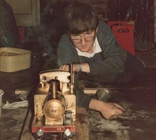
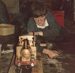
ith leaking side tanks fnally resolved the author poses with the engine during its frst successful steam test in


