2 minute read
r a s s h o p p e r B e a m E n g i n e
Valve setting
Having satisfied yourself that the assembled parts all move freely with one another the last ob is to set the valve timing (fg 69) This is done in two stages
Setting the
cam
Note that because of the mechanism of the beam, the centre of the clevis in the connecting rod will N T be in line with the shaft and pin of the crank at 0 degrees to the base – so do not bother to try and position all three centres in a straight line
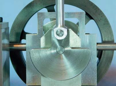
Turn the crankshaft until the crankpin is at its highest point in relation to the base Another way to look at this statement is that the centres of the crankshaft and crankpin need to lie on a line at 0 degrees to the base hen that position has been achieved turn the cam so that the two e ual peaks on the profile are exactly the same amount distance below the face of the top surfa ce of the cam follower The cam should now be secured by tightening the M x 10 grub screw (photo 144)

Setting the valve spool
Tighten the clamp screw in the valve lever cam
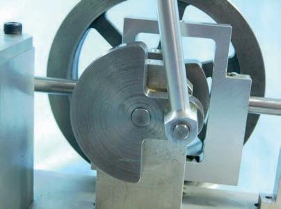
Turn the crankshaft until the crankpin centre is at 0 degrees on from T C, and on the same hori ontal centre as the crankshaft
Coincidentally this is the same centreline as the cam follower shafts 52 5 above the base (photo 145) ith the crankshaft in this position, carefully rotate the spool valve lever on the cross shaft until the upper face of the spool is exactly flush with the lower face of the ports in the top of the cylinder block Nip up’ the clamp screw otate the engine at least a full turn and bring the crankpin back to the 0 degree position
Check to see the spool is still in the correct position, resetting if necessary hen this is the case tighten the clamp screw (photo 146)
F G Spool Setting

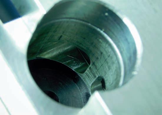
otate the crankshaft until the crankpin centre is at 270 degrees from T C, and on the same hori ontal centre as the crankshaft and cam follower shafts (photo 147). ith the crankshaft in this position, without moving the crankshaft, turn the engine on its cylinder block end until you can see into the end of the valve block
The end of the spool should be exactly flush with the upper face of the lower port in the cylinder block If not, slacken the clamp bolt and ad ust until the spool faces are in exactly e ual positions in relation t o the ports at both 0 and 270 degree crankpin positions. etighten the clamp bolt (photo 148)

First test run
For the least amount of noise it is a great help if the vacuum cleaner you use as a power source has a variable speed, or at least high and low speeds, which should be set to the lowest - otherwise ust accept the noise ush the control valve handle so the top is fully over towards the cylinder block Connect your chosen cleaner hose to the inlet port of the control valve and swi tch the cleaner on ou should now hear the sound of the vacuum being drawn through the Spill’ port in the control valve base, as the supply of vacuum to the engine valve block is closed Slowly rotate the control valve turning the flywheel away from either of the dead centres if it doesn’t start to rotate ou should find the engine speed
Responds To The Rotation Of The Control Valve
Hopefully you have arrived at this point with an engine that responds to the position of the control valve and most importantly will run slowly, so that the mechanism’s movement may be observed ou will have experienced a pleasure that is becoming increasingly rare The skills experienced are transferable to most forms of mechanical engineering, sadly once commonplace


