5 minute read
F i t t i n g D i g i t a l Re a d O u t s t o a Wa r c o
W
Graham Astbury describes
The readout
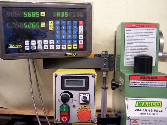
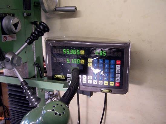
The readout is a fairly large bo with the connectors on the rear for the mains in and the (very generously long) leads from the sensors The location of this bo is purely down to personal choice so I decided to fit it on the right hand side of the machine column This is how it would appear to be fitted in the instructions supplied In the end, I had to have two goes at fitting the bracket (hands up those who have never made a mistake ) before it was in a reasonably suitable position Points to note are that if it is mounted on the head ( a is), it will, of course, move up and down as the head moves up and down However, the hand wheel for the a is will interfere with a head-mounted display as the head moves up towards the top of the column Similarly, it is likely that the three levers to move the quill may get in the way of the display and it may be difficult to operate the quill
Drilling Detail For Display Mounting Arm
In the end, I decided that column mounting was probably the best bet but I had previously fitted a pair of low-voltage lamps to the lower edge of the head, so that as the head is moved up and down, so the lights follow and the illumination of the cutter is fairly constant Mounting the display on the column meant that as the head is moved up and down, the display can become obscured by the lamp mounting brackets. It is up to you where you put the display.
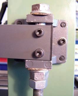
I did find that the pivoting arrangement for the display unit was difficult to tighten up sufficiently to keep it from swinging about, so I modified the arm and pivot by crossdrilling two holes through the pivot bolt (I used an M12 0 bolt that I happened to have ‘in the stores’), and using M5 cap-head screws for locking the bolt to the arm (photo 13) I also inserted steel washers and nitrile rubber-bonded cork washers to provide a little ‘grip’ to keep the arm in the position that I placed it I also fitted a locknut to maintain the pressure when the display was moved The correct order of assembly of the bolt, washers and nuts is shown in photo 1 The dimensions that I used for modifying the arm are shown in fg 16. The modifications to the bolt and the required washers are drawn in fg 17 One of the steel washers should be soldered to the underside of the head of the bolt to provide the fi ed surface for the rubber bonded cork to grip and the other washer is soldered to the nut adjacent to the bracket This time I used a zinc-chloride based flu (Baker’s Soldering Fluid® - usual disclaimer) as I could remove all the flu he fnal position for the display mounting bracket. residues simply by scrubbing in hot water
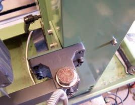
In photo 1 , the mounting bracket is fitted centrally to the column This was a mistake in my case and I ended up having to move the bracket away from the column, as the display when fitted fouled the column The new offset is shown in photo 14. This required another bracket (fg 18) and two more holes drilled into the machine column Hindsight is wonderful The final location of the display on its mount is shown in photo 15 I took care to make sure that when drilling the column, the drill bit would go straight through into the hole down the column rather than coming through part of the wall of the column, which would have certainly broken the drill
Final thoughts
aving fitted the DR s, I was very pleased with the result However, one thing that I did find was that the DR s do tell you that the gibs are not properly adjusted on the machine If the table is moved to the appropriate position and then the table locks are used, quite often the reading alters by 0 00 mm as the table locking screws are tightened This is caused by the table moving slightly as the table is locked when the gibs are tightened I found that this could be eliminated by careful adjustment of the gibs
The question of fitting a DR to the a is also arose At the time of buying the DR s and the display, I considered that as the quill had its own small DR , I would not need one However, there has been a time or two where the travel of the quill has been insufficient and I have had to move the head up and down the column, which then relies on the graduations on the handwheel and the linear scale fitted to the column To date, I have not found this to be a serious limitation, so I shall manage without it
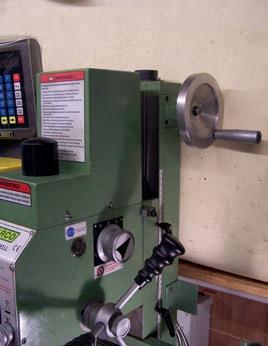
In terms of performance, I now use the milling machine instead of the drilling machine if drilling more than one hole in an item and using the digital positioning means more accuracy I regularly use the centring facility so that I can cross-drill shafts accurately without a jig The drill chuck is centred over the shaft and locked Then a spotting drill is used to start the hole, finishing with the correct size of drill and it is always spot on Accuracy for milling has improved in that instead of counting the turns and allowing for backlash, I can simply set the coordinates and watch the display, stopping at the correct place and then moving on to the ne t cut After a fair amount of use, I had found that the positioning of the digital readout panel on the right-hand side of the machine was less than ideal Under some circumstances, the handles for moving the quill get in the way of reading the panel as does the support for the work lights (photo 1 ). Therefore, I decided to move it to the left-hand side of the machine and position it on top of the control bo with the speed adjustment and speed read-out (photo 16) This proved easier than I thought and it simply needed a small plate making (fg 19) to fasten to the rear of the speed control bo The small half-circle cut out is to clear one of the screws in the speed control bo I used the two screws at the top of the rear of the control bo to secure the plate These screws were long enough in my case, but you might need slightly longer screws on your machine. The DR bracket is then fastened to the plate As I am fairly tall, the height of the read-out when the head is moved to the top of the a is is not a problem but those of smaller stature may find it needs tilting forward The move of the DR from right-hand side to the left-hand side leaves the right-hand side of the machine clear to allow the handles for the quill to be unobstructed (photo 17)
Would I fit DROs again?
I did find it a very useful learning e ercise which taught me a lot about my machine and about drawing the parts so that they actually fit together as intended However, it did take a lot of time in planning and making the various parts, so the small e tra outlay for having them installed by the supplier does have a huge attraction Knowing what I do now then, I would have ordered the machine with the DR s already fitted I noticed that in the instructions, the a is scale is fitted to the rear of the table, but the resultant reduction in table travel due to this is not stated in the manual Similarly, the Y a is scale is fitted to the left hand side of the machine to avoid the Y a is locking screws


