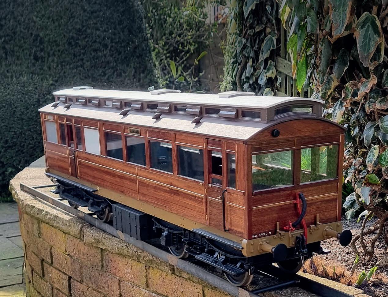
















❖ T H E O R I G I N A L M A G A Z I N E F O R M O D E L E N G I N E E R S Vol. 230 No. 4715 21 April – 4 May 2023 Join our online community www.model-engineer.co.uk H A R R O G AT E Rev i v a l of a p o p u l a r s h ow LNER Saloon D i r e c t o r s ’ c a r r i a g e w i t h a l o n g h i s t o r y N o Vo l t Re l e a s e M a c h i n e t o o l s a f e t y f e a t u r e Learning Lining If at first you don’t succeed… COVER FEATURE
Published by Mor tons Media Group Ltd, Media Centre, Morton Way, Horncastle, Lincs LN9 6JR Tel: 01507 529589 Fax: 01507 371066

© 2023 Mor tons Media ISSN 0026-7325


www model-engineer co uk


EDITORIAL
Editor: Mar tin R Evans
Deputy editor: Diane Carney
Designer: Druck Media Pvt Ltd
Club News: Geoff Theasby
Illustrator: Grahame Chambers
Publisher: Steve O’Hara
CUSTOMER SERVICES
General Queries and Back Issues
01507 529529
Monday-Friday: 8 30am-5pm Answerphone 24hr
help@classicmagazines co uk
www classicmagazines co uk
ADVERTISING
Group adver tising manager: Sue Keily
Adver tising: Angela Price
aprice@mor tons co uk Tel: 01507 529411

Ad production: Andy Tompkins
By post: Model Engineer adver tising, Mor tons Media Group, Media Centre, Mor ton Way, Horncastle, Lincs LN9 6JR
PUBLISHING
Sales and distribution manager: Carl Smith
Marketing manager: Charlotte Park
Commercial director: Nigel Hole
Publishing director: Dan Savage
SUBSCRIPTION
Full subscription rates (but see page 546 for offer): (12 months, 26 issues, inc post and packing)

UK £128 70 Expor t rates are also available, UK subscriptions are zero-rated for the purposes of Value Added Tax
Enquiries: subscriptions@mor tons co uk
PRINT AND DISTRIBUTIONS
Printed by: Acorn Web Offset Ltd , W Yorkshire
Distribution by: Seymour Distribution Limited, 2 East Poultry Avenue, London EC1A 9PT
EDITORIAL CONTRIBUTION


Accepted photographs and articles will be paid for upon publication Items we cannot use will be returned if accompanied by a stamped addressed envelope and recorded delivery must clearly state so and enclose sufficient postage In common with practice on other periodicals, all material is sent or returned at the contributor’s own risk and neither Model Engineer, the editor, the staff nor Mortons Media Ltd can be held responsible for loss or damage, howsoever caused The opinions expressed in Model Engineer are not necessarily those of the editor or staff This periodical must not, without the written consent of the publishers first being given, be lent, sold, hired out or otherwise disposed of in a mutilated condition or in other unauthorised cover by way of trade or annexed to or as part of any publication or advertising, literary or pictorial manner whatsoever
Vol. 230 No. 4715 21 April – 4 May 2023
548 SMOKE RINGS
News, views and comment on the world of model engineering
549 THE 2023 HARROGATE MODEL ENGINEERING EXHIBITION
John Arrowsmith visits a revived show in a renewed hall
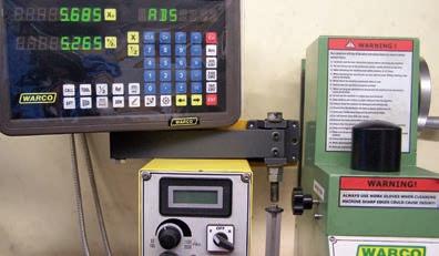
555 FITTING DIGITAL READ OUTS TO A WARCO
Graham Astbury explains how he fitted the scales to a Warco WM16 milling machine
558 COMPLETING BRIDGET
Jon Edney concludes the construction of his first locomotive
560 THE STATIONARY STEAM ENGINE

Ron Fitzgerald tells the story of the development of the stationary steam engine
562 THE EATING OF ELEPHANTS
Steve Goodbody argues that anything is possible if you take it a bite at a time
567 CLUB DIARY
Future Events
568 A FIVE-INCH GAUGE 0-4PADARN RAILWAY TENDER LOCOMOTIVE
Luker presents Fire Queen, a Welsh slate quarry locomotive
SUBSCRIBE & SAVE UP TO 49%
See page 546 for details
573 GRASSHOPPER BEAM ENGINE
Mar tin Gearing describes a half beam engine suitable for a beginner
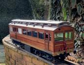
576 BUILDING THE NORTH EASTERN DIRECTORS' SALOON
Mike Glegg builds an NER inspection saloon in five-inch gauge
579 FLYING SCOTSMAN IN 5 INCH GAUGE
Peter Seymour-Howell builds a highly detailed Scotsman based on Don Young’s drawings
584 UNDERSTANDING NO VOLT RELEASE (NVR) SWITCHES
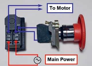
Luis Trincão explains how this safety feature works and how to make use of it
588 LNER B1 LOCOMOTIVE
Doug Hewson presents a true to scale 5 inch model of Thompson’s B1
592 CLUB NEWS
Geoff Theasby compiles the latest from model engineering clubs around the world
562

http://www facebook com/modelengineersworkshop


http://twitter com/ modelengineers

O N T H E C O V E R . . .
A five-inch gauge model of a Nor th Eastern Railway inspection saloon (photo: Mike Glegg)
584 555
www.model-engineer.co.uk
–
This issue was published on April 21, 2023 The next will be on sale on May 5, 2023 ❖❖ THE OR G NAL MAGAZINE FOR MODEL ENG NEERS –Jo n o r on ne ommunity www mo e -e g nee co uk H A R R O G AT E Re i l o pop sho LNER Saloon D recto s carr age wi h a ong history No Volt Release Machine ool sa ety ea ure Learning Lining f at first you don t succeed COV R F A U E
543
www.model-engineer.co.uk














P R I N T O N LY Q u a r t e r l y d i r e c t d e b i t fo r £18.00 1 ye a r d i r e c t d e b i t fo r £65.00 1 ye a r c r e d i t / d e b i t c a r d fo r £70.00 P R I NT + D I G ITA L Q u a r t e r l y d i r e c t d e b i t fo r £21.00* 1 ye a r d i r e c t d e b i t fo r £82.99* 1 ye a r c r e d i t / d e b i t c a r d fo r £84.99* D I G I TA L O N LY 1 ye a r d i r e c t d e b i t fo r £49.00* 1 ye a r c r e d i t / d e b i t c a r d fo r £52.95* *Any digital subscription package includes access to the online archive Enjoy 12 months for just £65 GREAT REASONS TO SUBSCRIBE > Free UK deliver y to your door or instant download to your device > Great Savings on the shop price > Never miss an issue > Receive your issue before it goes on sale in the shop SUBSCRIBE AND SAVE L MAGAZINE FOR MODEL ENGINEERS V 9 N 70 4 - 1 m ou online community www m del-enginee c uk EDERATION AGM d Autumn Rally at Little Hay Midlands Show First impressions ❖❖ THE ORIGINAL MAGAZINE FOR M V 3 4 11 J n our n ne c mmu SCOT IMLEC 2023 We invite entries for this year s efficiency compeition We visit a bobb ❖❖ THE ORIGINAL MAGAZINE FOR MODEL ENGINEERS 4712Jo n ou on ne commun ty mode -eng nee L i n co l n s h i r e L i n e Exploring the history of the Lincolnshire Coast Light Railway h u r c h the 150th the s EC 2023 rd to the small ficiency competit on We V t Rye d a l e We tak p Nor th Yorksh re SAVE 49%
w w w.classicmagazines.co.uk /MEDPS 01507 529529 and quote MEDPS Lines open Monday to Friday 8 30am – 5 00pm GMT Offer ends December 31, 2023 Subscriptions will start with the next available issue Direct Debit payments will continue on the agreed plan unless you tell us otherwise To view the privacy policy for MMG Ltd (publisher of Model Engineer), please visit www mortons co uk/privacy Please visit www classicmagazines co uk/terms for full terms & conditions
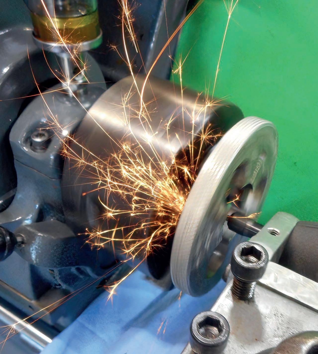
Jaw Regrinding - Pete Barker
MARTIN EVANS Editor

Engineering and Science
On page 560 Ron Fitzgerald describes how mathematical analysis came to be used for the first time in England as a tool in engineering design. He also mentions how England, despite leading the way into the Industrial Revolution, adopted this approach to engineering rather later than, for instance, France
I say England, rather than Britain, because Scotland, as Ron points out, was rather ahead of England in the academic study of engineering science Brunel, who was educated mainly in Paris, was one of the first engineers in Britain to employ mathematics in his profession.
mathematics with no practical use until about a hundred years later The former now forms the basis of the design of digital systems, notably computers, and the latter has wide application in signal processing, chiefly in error correction and encryption Without these mathematical techniques, many of our modern gadgets, like iPads, high definition TV and mobile phones, simply would not exist It’s the same story in other areas of technology For instance, our modern knowledge of the workings of DNA has led to the development of new therapies for a wide range of disorders
LittleLEC website (www littlelec co uk) The closing date is April 28th


Bradford Cup
The nominations for the Bradford Cup are now in and it’s time to star t voting! The Cup is awarded to the best ar ticle or series in Model Engineer during the year 2022 We have had only three nominations this year, as follows:
Club News – Geoff Theasby LNER B1 Locomotive – Doug Hewson
The Eating of Elephants –Steve Goodbody
DIANE CARNEY Assistant Editor

The late application of science, more generally, to engineering has been a consistent theme for many centuries We’ve had steam engines since the seventeenth century but the relationship between heat and work was not fully understood until the middle of the nineteenth century, by which time the entire country was criss-crossed by steam railways relying on that principle Cathedrals and bridges have been constructed with a high degree of confidence for many centuries but, again, the mathematics behind the analysis of structures is less than two hundred years old Empirical rules underpinned the design of these structures until then Semiconductors were discovered and used before quantum mechanics was devised as a way to describe how they work
During the 20th century, though, with the growth of ‘high technology’, it seems that this situation has in many cases been reversed, which could be seen as a key stage in the development of engineering as a scientific discipline Branches of science and mathematics previously considered to have no practical application have led to new technical developments For instance, symbolic logic and group theory, both developed in the nineteenth century, were considered to be ‘pure’
Perhaps that early application of science and mathematics to technology, highlighted by Ron in his article, reached a significant point sometime during the last century, where the science began to inspire the engineering, rather than the other way round
IMLEC and LittleLEC
Now that spring is well and truly here it’s time to make sure you have sent in your entries for whatever competitions you may think of entering The deadlines for both IMLEC and LittleLEC are looming so, if you are going to take the plunge, now is the time to make sure your entry is in!
IMLEC takes place this year at the Bristol club’s Ashton Cour t track from the 7th to the 9th July You can find more information about entering and the conditions of entry in issue 4711 of Model Engineer (24th February) or on the IMLEC website (www imlec uk) I par ticularly recommend the ‘teaser trailer’, accessible at the bottom of the ‘hamburger menu’. So, do enter, or come and watch, to help the Bristol club celebrate 50 years at Ashton Cour t The closing date is April 30th
Owners of smaller locomotives (less than 50lb dry) may wish to enter LittleLEC, which takes place at the Swansea club’s track at Derwen Fawr on the weekend of the 10th and 11th of June Details may be found in issue 4712 (10th March) or on the
Please register your vote with me before the end of May –one vote of course per reader The simplest way of doing this is by email (MEeditor@ mor tons.co.uk). In that case please star t the subject line with ‘Bradford Cup’ and follow that with the name of the ar ticle Any content in the message will not be relevant to the vote (This keeps counting the votes simple for me ) Alternatively, if you don’t have access to email, you can write to me with your vote In the event of a tie the editor will have the casting vote
The result will be announced in June.
Castings for 3 Inch Fowler
A reader asks where he might find castings, or maybe the patterns, for Tony Webster’s 3 inch Fowler steam wagon This was serialised in Model Engineer nearly 20 years ago I haven’t seen them adver tised anywhere and I don’t know of any stockist who has them so I wonder if anyone knows where these may be found
Mar tin Evans can be contacted on the mobile number or email below and would be delighted to receive your contributions, in the form of items of correspondence, comment or ar ticles.
07710-192953
MEeditor@mor tons co uk
Model Engineer 21 April 2023
548
T h e 2 0 2 3 H a r r o g a t e
M o d e l E n g i n e e r i n g & Model Railway Exhibition
There was a welcome return to Harrogate for the 2023 Model Engineering and Model Railway Exhibition This event, after quite a long gap, provided an excellent oppor tunity to showcase two aspects of our great hobby


The last model engineering exhibition held here was housed in the same hall but during the intervening years a superb new building has replaced the old Hall 1. This presented a wonderful new space in which to hold the event
It was warm, well lit and well laid out with easy access for everyone including wheelchair users The central cafe area between Halls 1 and 2, as always, provided a good area to rest a while and enjoy some refreshments Hall 2 provided the space for the majority of the model engineering clubs and societies Both
groups provided a wealth of fine displays and models emphasising the great engineering skills which still abound in this part of the country However, the weather intervened with the biggest snowfall of the winter This did have an unfortunate effect on attendances on the opening Friday; indeed a number of traders didn’t make it because of the weather Saturday made up for it though with both halls being very busy with interested visitors Having displays of both model engineering and model railways together did provide a great deal of interest for all visitors as the crossover between the two hobbies was much in evidence The difficulty for me was knowing where to start with such a tremendous selection of superb models to see I will start with the Model Engineer and Model Engineers’
Workshop magazines stand who had a comprehensive display of the magazines and books available from our publisher, covering a wide range of topics, many depicted in the models on display Conveniently displayed right next to our stand was the wonderful array of models, both static and operating, provided by the Pickering Experimental and Engineering Society – or PEEMS as everyone knows them Once again they excelled with some fine e amples of skilled model engineering The star of their display was a new model, still under construction, by Mike Sayers of a 40 fine scale model of the 1926/27 Delarge 15S8 British GP engine that powered the car to victory at Brooklands (photo 1) The model itself was mounted on a display board fitted with a mirror so the underside detail could be inspected
549 www.model-engineer.co.uk >>
P A R T 1
John Arrowsmith visits a new exhibition in a new exhibition hall
The 4 5 Blower Bentley built by Mike Sayers and shown on the PEEMS stand
1 2
A superb example of a Delarge 15S8 GP Engine under construction by Mike Sayers.
Building tools and equipment accompanied the display As usual the workmanship and detail was exemplary and was a magnet for visitors with Mike answering their questions in his usual, quietly-spoken and wellpractised way To add to this, another distraction was the 1/3 scale 4 5 litre Blower Bentley engine built by Mike (photo 2) There is always so much to see from this club which has
an almost endless production rate The selection of models from Brian Stephenson would fill a stand on its own There was also a very nice 4½ inch scale Foden Steam lorry on the stand built by David & Adrian Hick (photo 3)

Located in Hall 1 were a selection of larger traction engines which again attracted a lot of attention The 6 inch J & H McLaren compound


550 Model Engineer 21 April 2023
Tony Bickerstaffe’s excellent 7¼ inch gauge A4 Locomotive, Flying Fox
Thunderbolt the 7¼ inch gauge American locomotive built by the Leeds Grammar School boys in the late 1960s.
The 4½ inch scale Foden Lorry built by D & A Hicks shown on the PEEMS display
A fne 6 inch J & H McLaren traction engine and living van
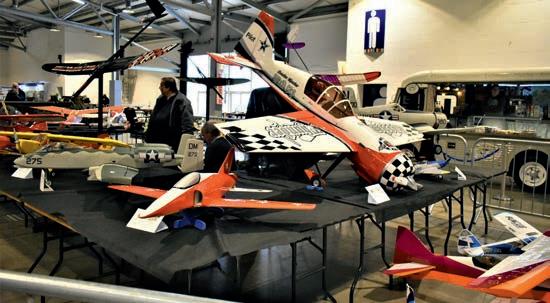
Part of the large, colourful display of model aircraft by the Harrogate Model Flying Club
A good example of a G5 0-4-4 Tank engine built by Norman Ash
3 4 5 6 7 8 9
This 20 ton bottom drop Coal Wagon on the 7¼ inch Gauge Society stand
traction engine and living van were located in a position that provided good access for visitors (photo 4) No builder’s or owner’s information was available for this display so I cannot enlighten you Moving into all 2, for the first time visitors were faced with an excellent and comprehensive display of model aircraft by the Harrogate Model Flying club (photo 5) I think this display covered a wide range of prototypes and all were well built and presented Adjacent to this display was the 7¼ inch Gauge Society who again displayed an eclectic mix of locomotives and rolling stock Included on the stand was a very nice model of a G5 0-4-4 locomotive that has been built by Norman Ash who, as a newly promoted fireman, worked on this engine in 1952 The model was completed in 2022 (photo 6) A fine e ample of an LNER 20 ton Bottom Discharge Hopper wagon (photo 7), the sort of wagon which would have worked with the G5, added further interest to the display.
Taking centre stage, however, was the superb LNER A4 4-6-2 being built by Tony Bickerstaffe This model of Silver Fox is showing exemplary workmanship in both the buil d and finish (photo 8) When completed it will be a joy to see in operation

The Leeds Society of Model & Experimental Engineers had a wide range of models

and equipment on their stand with the pride of place being a 7¼ inch gauge model of an American 4-4-0 tender engine, Thunderbolt (photo 9) This locomotive also has an interesting history having been built by the boys from Leeds Grammar school in the late 1960s (Oh, for schools like that these days!!) The building of this locomotive was published in M E magazine in March 1971 and hopefully a report of that endeavour and its refurbishment by present owner, Mark Batchelor, will be published in a future M E issue It was a real eye catching model Of course, the Leeds Society includes a great deal more than one locomotive and in complete contrast was a quality model of a Clarkson Steeple Engine built by Geoff Shackleton (photo 10) A pair of LNER 4-4-0 Atlantics were also prominent, one in 7¼ inch gauge and one in 5 inch gauge, but the interesting detail here was that the larger engine was fitted with outside Walchaerts valve gear, something that I have not seen before (photo 11)
The Scunthorpe Society of Model Engineers was another well filled display of members work with the 5 inch gauge 16 inch Naval Gun Set built by Vic Crossman standing out (photo 12) A number of excellent wagons and locomotives

created a good balanced display The Clayton Railbus was an unusual model but extremely well made (photo 13)

I liked the presentation on the York City & District SME display where they had created
a scale model of their own track and site buildings Included was a scale raised running track with a small Diesel shunter and two passenger carriages driving round the track (photo 14) Another intriguing model was
551 H A R R O G A T E www.model-engineer.co.uk >>
Geoff Shackleton’s Steeple Engine from the Leeds SME
An excellent pair of LNER 4-4-0 locomotives part of the Leeds SME display.
Vic Crossmans 5 inch gauge 16 inch Naval Gun mounted on its match trucks.
A rare model of Claytons Railcar built by Martyn Parsons from the Scunthorpe Society
10 11
12 13
still in good working
no indication whether it was a club display or a collection of individuals However, one model was identified as being the latest creation from Alan Crossfield The inch gauge GWR Pannier tank 0-6-0 was up to Alan’s expert standard with exquisite workmanship being shown in every aspect of the model (photo 16) The cab layout is an amazing piece of work in such a confined space (photo 17) I have built a similar model, but having seen this example I think I’ll put mine in the bin!! In the same group of models was another superb example of fine model engineering. This was the Holmes Mill Clayton & Goodfellow Cross Compound engine built by Mick Keenan Wonderful workmanship and finish (photo 18)
From the Southport MEC was a well filled stand displaying a great range of model locomotives in a variety of scales They also had a locomotive representing each of the ‘Big Four’ companies pre British Railways A very nice 5 inch gauge LNER A4 was prominent, as was a well made but unpainted B1. A couple of GWR Halls plus an LMS Hughes Crab with a nice little Southern Q class provided a good display to ponder over (photo 19)
A club I have not seen at an exhibition in recent times was the Stockton & Darlington Model Engineers and they offered a good range of locomotives and stationary engines together with some


552 Model Engineer 21 April 2023
The York City & District display was a model of their main club site complete with working raised track
Just a coat of paint needed to fnish off Alan Crossfeld’s superb 5 inch gauge GWR Pannier Tank
A model of the Clayton & Goodfellow Cross Compound, Holmes Mill engine built by Mick Keenan
An amazing cab layout on the Pannier
A model workshop circa 1936 shown on the York City & District display the working Victorian Workshop which won a Silver Medal at the 1936 M E Exhibition (photo 15) This excellent model is
14 15 16 17
order and showed the typical workshop of the day with its overhead line shaft drives
18
A small display of high quality models was located next to the Southport MEC display but unfortunately it had
rolling stock. A couple of 7¼ inch gauge 9F boilers were a prominent feature (photo 20) and the staying in the firebo was something I had not seen before Each stay was drilled through from each end - just to the depth of the water space, not all the way through - so that should a stay crack at any time, the leak would be immediately noticed and identified (photo 21) Apparently this practice is now a feature of larger scale steel

boilers made commercially by a well known boiler maker.
Among the other interesting exhibits here was a small belt driven shaping machine which looked to be quite a substantial piece of equipment (photo 22)


Both the Northern Association of Model Engineering clubs and the Federation of Model Engineering Societies provided their usual range of information and services which all model engineering clubs can access

Four well presented boat clubs added that dash of colour which always brightens up the exhibition There were some very nice marine models on show but it was unfortunate that the promised boating pool where visitors might have
seen some of the models in action did not materialise The Kirklees MBC had a comprehensive selection of marine craft from warships to small fishing vessels and included a small set of steam plants suitable for marine work


553 H A R R O G A T E www.model-engineer.co.uk >>
Southport’s excellent display of locomotives in various gauges
A different approach to frebox stays
HMS Warspite in 1:72 scale built by Colin M Vass
A sturdy belt driven shaping machine.
Some of the very fne detail on HMS Warspite.
19 21 23 20 22 24
Two steel 7¼ inch gauge 9F boilers on the Stockton & Darlington stand
Adjacent to this stand were two outstanding examples of warships built by Colin M Vass Both ships were completely scratch built in 1/72 scale and seemed, to my untrained eye, to be complete down to the last small detail HMS Warspite (photos 23 and 24) was a master class in marine modelling and is portrayed as it was in 1942 after repairs in the USA It had the most battle honours of any ship in the Royal
Navy. This Gold Medal winning model had been a contender for the DOE Challenge Cup at the last M E Exhibition
The Bradford MES had a wide selection of models including a very nice 4 inch scale Burrell traction engine (photo 25) and an Isle of Man tram (photo 26) which has some superb timber work and lighting included The tram bogies have a difficult frame profile with a curved edge This


had been achieved using a welder to heat and change the profile as can be seen in the photo of a trial frame A regular event at their Northcliffe track is the annual Fun Run competition which involves high speed locomotives being timed around the 440 foot oval track Each engine is built for the event and each competitor is allowed three attempts Two circuits of the track takes about 28 seconds, that is, of course, if they stay on the track! Three of these engines were on display at the exhibition and some clever engineering and electronics are involved (photo 27) The LNWR Railway Society stand had a good selection of historical photos of this much admired railway company on show and these were accompanied by some excellent models of typical prototypes

The rebuilt Hall 1 was, of course, the place to see some wonderful smaller gauge layouts, none more so than the
amazing 200 foot long Heaton Lodge Junction Railway, the work of Simon George (photo 28). This large O-gauge layout represents about 1½ miles of the actual railway It is depicted in winter time, hence the frost on the ground and buildings It was started in 2015 after three years of research and is the work of one man, not a club project, although friends have contributed all the electronic controls and laser cut support structures The storage and marshalling yards are just as amazing as the scenic part of the railway It was so large that, photographing the whole length, it was difficult to get everything in focus but I hope my pictures give you a flavour of an amazing piece of work There were a number of other layouts which I will cover in the next report
A further report covering the exhibition will be published as Part 2

554 Model Engineer 21 April 2023
A 4 inch scale Burrell Traction Engine on the Bradford stand
A close up of one of the very fast Bradford engines
An excellent example of an Isle of Man tramcar on the Bradford stand
The scenic side of the Heaton Lodge Railway depicting a winter time with frost on the ground
continued 25 26 27 28
To be
F i t t i n g D i g i t a l Re a d O u t s t o a Wa r c o
W
Graham Astbury describes

The readout
The readout is a fairly large bo with the connectors on the rear for the mains in and the (very generously long) leads from the sensors The location of this bo is purely down to personal choice so I decided to fit it on the right hand side of the machine column This is how it would appear to be fitted in the instructions supplied In the end, I had to have two goes at fitting the bracket (hands up those who have never made a mistake ) before it was in a reasonably suitable position Points to note are that if it is mounted on the head ( a is), it will, of course, move up and down as the head moves up and down However, the hand wheel for the a is will interfere with a head-mounted display as the head moves up towards the top of the column Similarly, it is likely that the three levers to move the quill may get in the way of the display and it may be difficult to operate the quill
Drilling Detail For Display Mounting Arm

In the end, I decided that column mounting was probably the best bet but I had previously fitted a pair of low-voltage lamps to the lower edge of the head, so that as the head is moved up and down, so the lights follow and the illumination of the cutter is fairly constant Mounting the display on the column meant that as the head is moved up and down, the display can become obscured by the lamp mounting brackets. It is up to you where you put the display.
I did find that the pivoting arrangement for the display unit was difficult to tighten up sufficiently to keep it from swinging about, so I modified the arm and pivot by crossdrilling two holes through the pivot bolt (I used an M12 0 bolt that I happened to have ‘in the stores’), and using M5 cap-head screws for locking
the bolt to the arm (photo 13) I also inserted steel washers and nitrile rubber-bonded cork washers to provide a little ‘grip’ to keep the arm in the position that I placed it I also fitted a locknut to maintain the pressure when the display was moved The correct order of assembly of the bolt, washers and nuts is shown in photo 1 The dimensions that I used for modifying the arm are shown in fg 16. The modifications to the bolt and the required washers are drawn in fg 17 One of the steel washers should be soldered to the underside of the head of the bolt to provide the fi ed surface for the rubber bonded cork to grip and the other washer is soldered to the nut adjacent to the bracket This time I used a zinc-chloride based flu (Baker’s Soldering Fluid® - usual disclaimer) as I could remove all the flu
555 www.model-engineer.co.uk >>
he ftte
it l re o ts to this pop l r m chi e
ho
i
M 1 6 M i l l i n g M a c h i n e P A R T 3
Drilling detail for the display mounting arm.
from p 519, M E 4714 April 7 8 8 3 6 16 12
The arm for mounting the display
Continued
View on rear of display arm, showing holes for hex socket cap head screws Drill two holes Ø6 one side of arm only
13
Fig 16
he fnal position for the display mounting bracket.

residues simply by scrubbing in hot water
In photo 1 , the mounting bracket is fitted centrally to the column This was a mistake in my case and I ended up having to move the bracket away from the column, as the display when fitted fouled the column The new offset is shown in photo 14. This required another bracket (fg 18) and two more holes drilled into the machine column Hindsight is wonderful The final location of the display on its mount is shown in photo 15 I took care to make sure that when drilling the column, the drill bit would go straight through into the hole down the column rather than coming through part of the wall of the column, which would have certainly broken the drill
Final thoughts
aving fitted the DR s, I was very pleased with the result However, one thing that I did find was that the DR s do tell you that the gibs are not properly adjusted on the machine If the table is moved to the appropriate position and then the table locks are used, quite often the reading alters by 0 00 mm as the table locking screws are tightened This is caused by the table moving slightly as the table is locked when the gibs are tightened I found that this could be eliminated by careful adjustment of the gibs
The question of fitting a DR to the a is also arose At the time of buying the DR s and the display, I considered that as the quill had its own small DR , I would not need one However, there has been a time or two where the travel of the quill has been insufficient and I have
556 Model Engineer 21 April 2023
Details of the M12 x 80 bolt and washers for the mounting arm
The additional bracket for the display arm bracket
Modified M12 x 80 Bolt 22 42 25 80 Drill & tap M5 right through Ø26 Ø13 2 . 6 Mat’l: Mild steel 2 req’d Steel Washer Ø26 Ø13 1 . 5 Soft Washer Mat’l: Nitrile rubber bonded cork 2 req’d Fig 17 3 0 6 0 35 Drill & tap M5 1 0 1 0 Side Bracket Drill two holes Ø5 31 Mat’l: 45 x 45 x 4 RSA 1 req’d 4 Fig 18 14
had to move the head up and down the column, which then relies on the graduations on the handwheel and the linear
scale fitted to the column To date, I have not found this to be a serious limitation, so I shall manage without it
In terms of performance, I now use the milling machine instead of the drilling machine if drilling more than one hole in an item and using the digital positioning means more accuracy I regularly use the centring facility so that I can cross-drill shafts accurately without a jig The drill chuck is centred over the shaft and locked Then a spotting drill is used to start the hole, finishing with the correct size of drill and it is always spot on Accuracy for milling has improved in that instead of counting the turns and allowing for backlash, I can simply set the coordinates and watch the display, stopping at the correct place and then moving on to the ne t cut After a fair amount of use, I had found that the positioning of the digital readout panel on the right-hand side of the machine was less than ideal Under some circumstances, the handles for moving the quill get in the way of reading the panel as does the support for the work lights (photo 1 ). Therefore, I decided to move it to the left-hand side of the machine and position it on top of the control bo with the speed adjustment and speed read-out (photo 16) This proved easier than I thought and it simply needed a small plate making (fg 19) to fasten to the rear of the speed control bo The small half-circle cut out is to clear


one of the screws in the speed control bo I used the two screws at the top of the rear of the control bo to secure the plate These screws were long enough in my case, but you might need slightly longer screws on your machine. The DR bracket is then fastened to the plate As I am fairly tall, the height of the read-out when the head is moved to the top of the a is is not a problem but those of smaller stature may find it needs tilting forward The move of the DR from right-hand side to the left-hand side leaves the right-hand side of the machine clear to allow the handles for the quill to be unobstructed (photo 17)
Would I fit DROs again?
I did find it a very useful learning e ercise which taught me a lot about my machine and about drawing the parts so that they actually fit together as intended However, it did take a lot of time in planning and making the various parts, so the small e tra outlay for having them installed by the supplier does have a huge attraction Knowing what I do now then, I would have ordered the machine with the DR s already fitted I noticed that in the instructions, the a is scale is fitted to the rear of the table, but the resultant reduction in table travel due to this is not stated in the manual Similarly, the Y a is scale is fitted to the left hand side of the machine to avoid the Y a is locking screws
557 D R O www.model-engineer.co.uk
The alternative plate for left-hand side mounting of the DRO Display
The right-hand side is a lot less cluttered
The readout fastened to the right-hand side of the column.
15 16 r4 195 6 5 6 5 1 8 6 64 59 8 118 Mat l: Mild steel sheet 1 6mm thick Finish: two coats of paint - colour BS 4800: 08E51 Drill two holes Ø4 3 to fasten to speed control box Drill four holes Ø5 to secure dro bracket Fig 19
The readout moved to the left-hand side of the machine
ME 17
Co m p l e t i n g B r i d g e t
Interlude – the driving truck

My driving truck is a rather ad-hoc affair left over from a previous project (shown without roof in photo 48) I thought I might relate its history as an e ample of how things evolve As you will see from the picture it is a non-prototypical coach on a chassis with two bogies, each of two a les
In fact, this chassis was the first thing I made in my new
hobby I had intended to build a CliShay locomotive as a first project as described in the book Building the CliShay by Robert Maynard (ISBN 0941653420). The Shay designs were used in USA, especially for logging where there were tight curves and rough track The CliShay had a central vertical boiler and a vertically mounted twocylinder steam engine driving a lay shaft Power was then transmitted to the wheel by chains between the lay shaft and the inner a le of each bogie and thence to the outer a les
My plan was to build this but, instead of the steam engine, to use an electric motor to drive the layshaft powered by two car batteries, one over each bogie I would then add a suitable made-up casing So, I completed the chassis according to the book I was then disappointed to discover that it would not work on my garden track which has some bends of 20ft radius Ironically for a Shay, the bends were too tight and as the bogie turned, the roller chain from the lay
shaft ran up the side of the sprocket and jammed
I could not find a solution to this problem and had to abandon this chassis. Instead, I built a cruder chassis, the same si e, with two fi ed a les instead of bogies Clearly this solved the chain alignment issue – although much less elegant looking In fact, this locomotive (shown in photo 49) has served very well for the past five years and hauled many families happily around the track
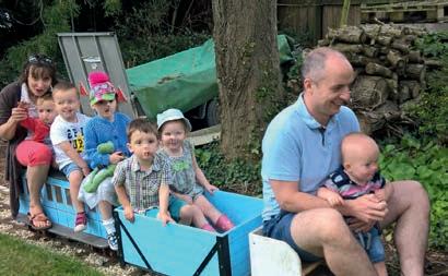
So, the question arose - what to do with the spare chassis Having two bogies, I decided it would make a nice coach and I constructed a coach body out of plywood and painted it to be visually appealing I put foot platforms on and ensured the roof and supports were strong It was then pressed into service as a sit astride coach
Considering this chassis was design for a locomotive –considerably less weight than a person - it ran surprisingly well and sometimes had to cope with large loads (photo 50)


558 Model Engineer 21 April 2023
E
P A R T
x p e r i e n c e o f a N e w b i e
5
Continued from p 533, M E 4714 April 7
Jon Edney achieves the completion of his frst locomotive project.
Battery locomotive
48 49
Driving truck (minus roof)
However, being intended for a locomotive, the chassis had no suspension at all To survive variations in the track the design used a ‘3 point’ system meaning that the weight was transferred into the bogies using two points on one bogie and a single point on the other – allowing the latter to rock to stay on during track perturbations This made the coach a bit unstable and prone to derailments In the end I retired it again and built two more sit-in trucks (see Riding Trolley, M E 4 586, May 11 2018, et seq )
This now brings us back to Bridget as I was looking for a ride on trolley that could take a large water tank and a car battery to power the pump

This big empty plywood bo was ideal I did make some corrections, moving to a four-point contact for the bogies and installing some firm springs to cope with track irregularities And so, the rest is history, as they say This has become my driving trolley and, so far, has risen to the job


Success at last
The coach, pressed into action as a driving truck, had plenty
of empty space inside and I was able to install a 10 litre water tank, a small 12V car battery, the electric pump and a switch I found suitable high pressure hose and fittings Actually, the fittings were billed as ‘for pressure washer’ and were relatively cheap but good quality They have a very positive connection and disconnection and I have had no problems with them Of course, I had to rework the plumbing on the locomotive to feed the new supply in but it was a chance to reuse the water filter previously made redundant when I reworked the injector supply
Photographs 51 and 52 show the new plumbing
Finally, I was able to fire up the locomotive and bring it up to full pressure safely and, not long after that, take it out on the track for the first time Photograph 53 was taken on the first passenger run, slightly blurry as it’s taken from a video What you can’t see are my furrowed brows and white knuckles but all went well I have run the locomotive about half a dozen times during the summer and it has run well with even beat and enough power to get up the fairly sharp incline in part of my garden track So far nothing has ‘fallen off’
Concluding thoughts
It took me about five years to complete the locomotive from collecting the castings, frames and a few pieces that a previous builder had started until the first run I took up this wonderful hobby in 2015 with no prior e perience of metalwork beyond using a hacksaw (which, of course, I discovered I had been doing wrong) I did a lot of reading
and, more by luck than judgement, bought a good size Harrison 10 lathe which has been wonderful and very forgiving I had never silver soldered anything and yet was able to make the boiler I had only a vague idea of what a milling machine was and yet I was able to make the rods and motion Somehow, I was able to muddle through and make this locomotive essentially from scratch The only two items I purchased as commercial parts were the injector and the cab pressure gauge (and of course a whole lot of nuts, bolts and rivets)
Of course, there are many superb engineers in the hobby who have completed apprenticeships and spent years in engineering companies and have skills and knowledge well beyond anything I could aspire to, but my observation is that, as a hobby, common sense, preparation, learning and practice are enough to make real progress with model engineering I sometimes read in Model Engineer people saying that our hobby will die away because young people are no longer learning the skills But I believe that the hobby will never die away so long as there
are people who are fascinated by machinery and have a desire to solve problems and make things They will find the skills they need
Today, we have the good fortune to have equipment beyond that available even 20 years ago I have found digital measurement tools, and especially the DRO on the milling machine, to be essential to enable me to do accurate construction In past days accuracy was dependent on the skills of the machinist but these new tools allow progress even without the skills that take years to acquire E cept for rough items I never mark out from a ruler I don’t own a bottle of marking blue Some may bemoan the loss of these skills but there are plenty of problems to solve at every step and problem solving is the key to satisfaction
To be honest, I find I have little interest in driving the locomotive other than to give pleasure to others As I often say to people, “the novelty of driving round your garden on a train wears off pretty quickly” So, I have launched into a new construction project – larger and more challenging – and I look forward to telling you about it in future years.
As I close I would like to pay tribute to Model Engineer magazine and all the contributors I have found it enormously helpful to see how e perienced people approach problems and I have learned a great deal On top of that the more general articles are a jolly good read
559 B R I D G E T www.model-engineer.co.uk
ME
Four ride on the coach (plus Kermit).
New connection to the feed pipe
First passenger run
50 51 52 53
New connection to the water supply.
Continued from p 470
M E 4713, March 24
T h e S t a t i o n a r y S t e a m E n g i n e
PART 45 – THE FIRST IRON BEAMS
John Banks and the Shelf Ironworks
Cast iron was already an old material when the first iron beams began to be used for structures and steam engines; it was the application that was without precedent Where long e perience of building in timber and stone had shown the safe limits of traditional materials there was no accumulation of empirical knowledge to assist in designing loadbearing cast iron structures The gap was to be filled by rationalised theor y and for the first time in histor y the use of mathematical analysis became a commonplace tool in engineering design.
This is not to say that the scientific theory of structures was new; there was a Continental tradition of fundamental theoretical analysis that extended back to Galileo which the eighteenthcentury French academiciens and the military schools of engineering had been energetic in e tending Before the advent of structural castiron the English contribution to these developments was marginal and the French Ecole had no counterpart on this side of the channel English universities re oiced in their disdain for science (Scotland was quite different with both Glasgow and Edinburgh niversities displaying a keen interest in natural philosophy ) Research and study of natural philosophy was left to the gentleman amateur or, increasingly, to the self taught efforts of a
rising generation of religious dissenters on conformism played a key part in sustaining science in eighteenth-century England and several regional centres of religious dissent became identified with an enthusiasm for the sub ect that was firmly orientated towards the practical needs of developing industry Amongst the most outstanding was the Westmorland town of Kendal which produced a disproportionately large number of mathematicians, scientists and industrialists Many were trained by the remarkable Quaker John Gough (1757-1825) Gough was blinded by smallpox at the age of three which did not prevent him from becoming a formidable mathematician e learnt his ini tial mathematics from the Mungrisdale teacher John Slee but subsequently was dependent upon his sister Dorothy for access to the more advanced literature Gough proved to be a highly proficient teacher In addition to educating his fellow uaker John Dalton in mathematics from 17 2 to 1790, he had great success in tutoring for the Cambridge scholarship. Several of his students became high wranglers including William Whewell, one of the pillars of the mathematical revolu tion that commenced in Cambridge in the eighteen-twenties The cult of the amateur mathematician extended beyond Kendal, down through Lancashire,
transcending class divisions Mrs Gaskell, the author, remarked upon handloom weavers working with a mathematical textbook at their elbow and popular polemics on the finer details of Euclid were common
John Banks emerged from this background Born in 1740, he was seventeen years older than Gough but the relationship between the two men, both resident in the same town and with identical interests, remains obscure By 1775 Banks had gained c onsiderable distinction as a peripatetic teacher of natural philosophy using an armoury of e perimental apparatus which he deployed in his public lecture circuit of the northern counties Evangelical in promoting the practical application of natural philosophy to industrial life, he saw mathematics as integrally built into the subject His lectures were accessible and keenly attended by the new generation of amateur scientific literati In 1775 the first of his books was published, An Epitome of a Course of Lectures on Natural and Experimental Philosophy. The printer and publisher was William Pennington of Kendal who handled the three subsequent editions and remained Banks’s choice for his later books, the Treatise on Mills of 179 and On the Power of Machines which appeared in 1803
The Treatise on Mills was published by subscription and
560 Model Engineer 21 April 2023
Ron Fitzgerald takes a look at the history and development of the stationary steam engine.


