

Sep 23 No.331 INSIDETHISPACKEDISSUE: SETTINGUPALATHETO TURNPARALLEL Settingupyourbenchgrinder toachievesharperlathetools GetmoreoutofyourworkshopwithMEW Jointheconversationat: www.model-engineer.co.uk MAKINGALARGEROTARYTABLEFROMACARFLYWHEEL. WORKSHOPTALES:NEVILLE SHUTE. MACHININGCURVESWITHTHE‘REPTON’RADIUSINGTOOL. SOCIETYOFMODELAND EXPERIMENTALENGINEERSATMMEX2023. ABRIQUETTECUTTERFORLIVESTEAMERS. DOWNTHEDRAIN–AKITCHENREPAIRANDALESSONLEARNT. THEASBY’SWRINKLES. BEVELGEARDEMONSTRATOR. ATAILSTOCK BORINGADAPTOR Safelyuseaboring headinyourlathe PeterBarkermoveshisMyfordontoanewbench. THEMAGAZINEFORHOBBYENGINEERS,MAKERSANDMODELLERSSEPTEMBER2023ISSUE330WWW.MODEL-ENGINEER.CO.UK FERGUSON’SPARADOXDEMONSTRATOR UsingtheFilengrèneprogramtodesignmodifiedgears GettingtheAnglesRight


EDITORIAL
Editor: NeilWyatt
Designer: DruckMediaPvt.Ltd.
Publisher: SteveO’Hara
Bypost: ModelEngineers’Workshop, MortonsMediaGroup,MediaCentre, MortonWay,Horncastle,LincsLN96JR
Tel: 01507529589 Fax: 01507371006
Email: meweditor@mortons.co.uk ©2022MortonsMediaISSN0033-8923

CUSTOMERSERVICES
GeneralQueries&BackIssues
01507529529
Monday-Friday:8.30-5pm
Answerphone24hr
ADVERTISING
Groupadvertisingmanager: SueKeily
Advertising: AngelaPrice aprice@mortons.co.ukTel:01507529411
ByPost: ModelEngineers’Workshopadvertising, MortonsMediaGroup,MediaCentre, MortonWay,Horncastle,LincsLN96JR

PUBLISHING
SalesandDistributionManager: CarlSmith

MarketingManager: CharlottePark
CommercialDirector: NigelHole
PublishingDirector: DanSavage
Publishedby: MortonsMediaGroup, MediaCentre,MortonWay,Horncastle, LincsLN96JR
SUBSCRIPTION
Fullsubscriptionrates(butseepage54foroffer): (12months12issues,incpostandpacking)–UK £56.40.Exportratesarealsoavailable–seepage 46formoredetails.UKsubscriptionsarezeroratedforthepurposeofValueAddedTax.
Enquiries:subscriptions@mortons.co.uk
PRINTANDDISTRIBUTIONS
Printedby:WilliamGibbons&SonWolverhampton
Distributionby:SeymourDistributionLimited, 2EastPoultryAvenue,London,EC1A9PT TelNo:02074294000
EDITORIALCONTRIBUTIONS
Acceptedphotographsandarticleswillbepaidforuponpublication.Itemswecannot usewillbereturnedifaccompaniedbyastampedaddressedenvelope,andrecorded deliverymustclearlystatesoandenclosesuf cientpostage.Incommonwithpractice onotherperiodicals,allmaterialissentorreturnedat thecontributorsownriskandneither ModelEngineers’WorkshopMagazine theeditor,thestaffnorMortonsMediaLtdcanbeheldresponsibleforloss ordamage,howsoevercaused.TheopinionsexpressedinMEWarenot necessarilythoseoftheeditororstaff.Thisperiodicalmustnot,withoutthewritten consentofthepublishers rstbeinggiven,belent,sold,hiredoutorotherwise disposedofinamutilatedconditionor,inanyunauthorisedcoverbywayoftradeor annexedtooraspartofanypublicationoradvertising, literaryorpictorialmatterwhatsoever.
Thisissuewaspublishedon11August2023. Thenextissuewillbeonsale15September2023.
Onthe Editor'sBench
BackintheWorkshop

Itseemslikeforever,butatlastmy workshopisfullyfunctional(althoughit seemstobeuntidyalready).Ofcourse assoonasmylatheswereproperlyset up,afriendcalledroundwitha‘little job’.Inthiscasemodifyingtheclamp washerofachopsawforaskimo thespigot,sothatitcan t25mmbore sawsinsteadof1”ones;apparentlythe costdi erencewasnearlyfourtimesas muchfortheimperialones!
Admittedlymostofmyrecent workshopactivityhasinvolved3D printing,howeverjudgingbythe amountofworkshopprojectsIsee thatuse3Dprintingalongwithother moretraditionaltools,ithasbecome mainstreamnow.
Irecentlydecidedto‘upgrade’someold microphonesbyconvertingthemtoXLR socketsforbalancedleads.Ofcourse theironyisthatevenreasonableones areridiculouslycheapthesedays,butI hadthreeandtwoofthemareusable quality,soIthoughtwhynot?Asearch forvarioustypesofXLRmaleconnectors
suitablefor ttingattheendofacylinder wasnotproductive,butIfounddouble endedmaleconnectorsthatlookedlike theycoulddothejob.A ercuttingthe shellsinhalfonthebandsawandtidying itup,Iwasabletomakesuitableholesin theendsofthemicrophones,‘milling’’a steppedrecesswithmytrustyDremel. Thehalf-shellsweregluedinplacewitha high-viscositysuperglue,andthenitwas justacaseofrewiringthem.
Incidentally,manymicrophonesmeans manycablesthatcanbehardtokeep trackof.AhandygadgetIbought recentlyisa‘bluetoothlabelprinter’.It ischargedfromUSBandholdsreelsof thermalprintlabels,whichitrecognises usinganRFIDtag!Aswellassimple labels,Igotareelofonesspecially forcableswithathinnertagtowrap aroundthecable,thenalargersection thatfoldsbacktosecurethetag.You designthelabelsonafreeapponyour phone,whichcanevengenerateQR codes.Anidealsolutionforkeeping trackofwhichplugiswhichmachinein theworkshop!
 NeilWyatt

3 September2023


4 September2023





5 September2023
9 ARotaryTablefrom AutomotiveFlywheels. KenLonieusedtwovintageRiley flywheelstomakealargerotarytable.
14 AnglesettingforBench Grinders.
AustinHughessimplifiestheprocessof settingtheanglesforsharpeninglathe toolswithjustabasicadjustablerestfor yourbenchgrinder.
19 RoundingThingsOff.
The‘Repton’radiusturning attachmenthasprovenveryuseful toHowardLewis,heshareshis experiencesandofferstipson sphericalturning.
22 Beginner’sWorkshop. ThismonthGeometerlooksat methodspreventingnutsfrom unscrewingduetoloadsorvibration.
23 WorkshopTales.
NevilleShuteNorway–novelist, engineer,entrepreneurandan accomplishedmodelengineer.
28 BoringfromtheLathe Tailstock.


Keithkeenshareshisdesignfora specialclamptoallowaboringheadto beusedinthelathetailstock.

31 Theasby’sWrinkles
Geoff Theasbysharessomeinteresting ideasforkeepingthingsorganisedin theworkshop.

34 ArtfulDodges. Inthismonth’sdodge,JohnSmith simplifiesaccuratelycentringworkon arotarytable.
36 DowntheDrain.
LaurieLeonardneededtorepaira cafetiere,andwasrudelyremindedofthe annoyingpropertiesofstainlesssteels.
38 “Filengrène”–So ware forGearDesign.
JacquesMaurelintroducessomeuseful freeso ware,andstartsthemaking ofademonstrationofFerguson’sGear Paradox.
42 TheMidlandsModel EngineeringExhibition. PlansfortheSocietyofModeland ExperimentalEngineersatMMEXin October2023.


44 SetUpYourLathetoTurn True.
PeterBarkermakesametalbenchfor hislathe,andthenexplainshowto setthelatheforoptimum accuracy.


50 FromtheArchives. Celebrating125yearsofModel EngineerwithWorkshopNotesfrom 1903and1928.
55 SettingUpforMillinga CompoundAngle.
R.Finchexplainsthemathematics ofsettingoutanangleinthree dimensions.


60 Bob’sBetterBevels–Postscript.


Wereachtheconclusionof BobReeve’sexplorationofthe worldofbevelgearswiththe completionofhisdifferential demonstration.

Contents ModelEngineers’Workshop www.model-engineer.co.uk 6 19 £5.75 Sep23 No.331 INSIDETHISPACKEDISSUE: SETTINGUPALATHETO TURNPARALLEL Settingup yourbenchgrinder to achievesharperlathetools GetmoreoutofyourworkshopwithMEW Jointheconversationat: www.model-engineer.co.uk MAKINGA LARGEROTARYTABLEFROM ACARFLYWHEEL. WORKSHOP TALES:NEVILLE SHUTE. MACHININGCURVESWITHTHE‘REPTON’RADIUSINGTOOL. SOCIETYOFMODEL AND EXPERIMENTAL ENGINEERS ATMMEX2023 ABRIQUETTE CUTTERFORLIVE STEAMERS. DOWN THEDRAIN– AKITCHEN REPAIR ANDA LESSON LEARNT. THEASBY’S WRINKLES. BEVELGEARDEMONSTRATOR. ATAILSTOCK BORINGADAPTOR Safelyuseaboring headinyourlathe PeterBarkermoveshisMyfordontoanewbench. THEMAGAZINEFOR HOBBYENGINEERS,MAKERSANDMODELLERSSEPTEMBER2023ISSUE330WWW.MODEL-ENGINEER.CO.UK FERGUSON’SPARADOXDEMONSTRATOR Using theFilengrèneprogram to design modified gears GettingtheAnglesRight GettingtheAnglesRight SUBSCRIBETODAY! GETYOURFAVOURITE MAGAZINEFORLESS DELIVEREDTOYOURDOOR! Seepage54-55fordetails.
Comingup… inournextissue
3 OntheEditor’sBench. Theeditorhascompletedsomeminorprojects!


50 ScribeALine. Morefeedbackandcommentfromreaders–Andaninteresting workshop.Wearealwayskeentohearfromyou–justsendan emailtomeweditor@mortons.co.uk.
54 OntheWire. Ourmonthlyroundupofnewsfromtheworldofengineering.
58 Readers’Tips
Ourwinnerthismonthhasatipforlivesteamers.Sendyour tipstomeweditor@mortons.co.uk,youcouldwinaprize.
66 Readers’Classifieds
Anothergreatselectionofreaders’saleandwantedads.
ONTHECOVER
OurcovershowsAustinHughe’s adjustablebenchgrinderrest,that usesthecrossslidefromaUnimat lathe,seepages14-18.


www.model-engineer.co.uk

WhynotfollowusonTwitter?twitter.com/
THISMONTH’SBONUSCONTENT
LogOntoTheWebsiteforExtraContent:


AllthelinksinJacquesMaurel’sarticleongeardesignaretobefoundat: www.model-engineer.co.uk/filengrene
Otherhottopicsontheforuminclude: Whydomoderncarengineshavedifferenttypesofbolttype headslikeTorxetc? IAgoodquestion,bySimonRobinson4. DamagedScrews&QCTPhelp!!! Extractingreluctantscrewsby MargaretTrelawny

MultipleBearingsinSpindle Thoughtsonspindledesignby SteveCrow.
HighSpeedMilling Tips,Tricks,SpeedsandBitsbyIainDowns.
ComeandhaveaChat!
Aswellasplentyofengineeringandhobbyrelateddiscussion,we arehappyforforummemberstouseittoshareadviceandsupport. Comeandjoinus–it’sfreetoallreaders!
September2023 7 MichaelCoxconverts anangleviceintoa tiltingworktable. Regulars Sep23 No.331 INSIDETHISPACKEDISSUE: SETTINGUPALATHETO TURNPARALLEL Settingupyourbenchgrinder toachievesharperlathetools GetmoreoutofyourworkshopwithMEW Jointheconversationat: www.model-engineer.co.uk MAKINGALARGEROTARYTABLEFROMACARFLYWHEEL. WORKSHOPTALES:NEVILLE MACHININGCURVESWITHTHE‘REPTON’RADIUSINGTOOL. EXPERIMENTALENGINEERSATMMEX2023. ABRIQUETTECUTTERFORLIVESTEAMERS. THEASBY’SWRINKLES. BEVELGEARDEMONSTRATOR. ATAILSTOCK BORINGADAPTOR Safelyuseaboring headinyourlathe PeterBarkermoveshisMyfordontoanewbench. THEMAGAZINEFORHOBBYENGINEERS,MAKERSANDMODELLERSSEPTEMBER2023ISSUE330WWW.MODEL-ENGINEER.CO.UK FERGUSON’SPARADOXDEMONSTRATOR UsingtheFilengrèneprogramtodesignmodifiedgears GettingtheAnglesRight
Website
Visitour
ModelEngineershashtag#MEW
HOMEFEATURESWORKSHOPEVENTSFORUMSALBUMS
CLASSIFIEDSEXTRASUBSCRIBEARCHIVESUPPLIERS


ARotaryTableFrom AutomotiveFlywheels
KenLoniemakesalargerotarytableusinganunusualsourceofmaterial.
Iamaretiredengineerfromthe SunshineCoastinQueensland, Australia.However,myexperience hasalwaysbeeninmanagementand designintheminingindustryandI haveonlyacquiredalatheandmillsince retirementandenjoymetalworkand restorationofoldcars.

A erpurchasingmyBridgeportmill, IalsopurchasedaVertexindexinghead whichIhaveusedforcuttingsplinesand gearsetc.However,atonestageIusedit tomillasemicircleonthemill.Disaster!I nowknowthattheVertexindexinghead isreallyonlyforindexingandmeant tobelockedwhenactuallymachining. Whenrotatingitwhilemilling,Istripped thethreadsthatthewormengageswith. Theyareonlyreallyslotscutintothe castirondrum.Fortunately,Iwasable topacktherotatingdrumupsothat thewormmeshedwithanundamaged portionofthedrumgear.
Irealisedaseparaterobustrotatingtable formillinganycircularpath,wasneeded. AnyunitsIlookedatontheinternetwere expensive,soIcontemplatedmaking myown.AsIamintooldcarsandold ywheelsandringgearsarereadily available,IwonderedifIcouldrotateone ywheelontopofanother,possiblywitha rowofballbearingsseparatingthem,and thenrotatethetop ywheelwithaworm madetomeshinwiththeringgearonthe top ywheel.Icouldalso ttheindexing platesfrommyVertextouseitasan indexinghead.
Iobtainedtwoold ywheelsfrom 1950EnglishRileysandoneringgear inreasonablecondition.Themost complexpartoftheprojectturnedout tobecalculationofthewormangles andpitchetc.
TheWormgear
Theringgearhasanoutsidediameterof 13.25inchesand104teeth.
FromIvanLaw’sexcellentbookon
GearsandGearCutting,diametral pitchisDP=(N+2)/OD,whereODisthe outsidediameter.
HencetheDPoftheringgearteethis 8.Iintendtomakeawormthatwillbe angledupatitshelixangletomeshwith theringgear.
Nowthecircularpitchisgivenby: CP=PI/DP=0.3927inches.
Thehelixangleofthewormisgivenby: Tan(HelixAngle)=CP/(PI*PCD) WherePCDispitchcirclediameterof theworm.
ForDP=8,ODofthewormisgivenby: W=PCDoftheworm+0.250inches (Assumingthesamethreaddepthas foraspurgear)asshownonpage88of IvanLaw’sbook.
Therefore:
Tan(HelixAngle)=CP/(PI*(W-0.250)) However,thecircularpitchofthe wormislessthanthatoftheringgear becauseofthehelixangleoftheworm. Thecircularpitchofthewormisequalto thecircularpitchoftheringgear,divided byCos(HelixAngle).
TheadjustedHelixAngleistherefore givenby:
Tan(HelixAngle)=0.3927/(PI*(W0.250)*Cos(HelixAngle))
Thisreducesto:
Sin(HelixAngle)=0.3927/ (PI*(W-0.250))
Mylathehasaleadscrewof8tpiand thereforewiththestandardchangewheel ratioof1:1,(andwiththequickchange gearboxsetat8tpi),theleadscrew advancesoneeighthor0.125inchesfor everyrevolutionofthemandrel.
FromIvanLaw’sbookpage92,the requiredchangewheelratioforthelathe tocuttheappropriatewormthread,is givenby:
R=0.125/(adjustedCircularPitch)
R=0.125*Cos(HelixAngle)/0.3927
Thesetwoequationscanbesolved toprovide:
R=(0.125/0.3927)*Square
Root((1+x)*(1-x))
Where:
x=0.3927/(PI*(W-0.250))
WecannowcalculateRforvarious valuesofWuntilweendupwitha practicalvalueforthewormODandan achievablechangewheelratioforthe lathe.
Wecanthenuse:
Sin(HelixAngle)=0.3927/(PI*(W-0.250)) tocalculatethehelixangleoftheworm. Practically,weneedtoendupwitha wormODofaroundoneinch.
Iendedupselectingachangewheel ratioofR=0.312andawormODofW= 0.881inches.ThisresultsinaHelixAngle of11.43degreessothewormwillbe tiltedat11.43degreestotheplaneofthe ywheel.
Thecircularpitchofthewormis givenby:
CP(adjusted)=0.3927/Cos(HelixAngle) =0.4006
Thisequatestoawormthreadsperinch of1/CP(adjusted)=2.496tpi,Say2.5tpi.
NowusingfactoringasperIvan Law’sbookpage90,0.312=(26*30)/ (50*50)wherethe rsttwogearsare thedrivengearsandthetwo50tooth gearsarethedrivers.Thisisalsoequal to(26*48)/(80*50).However,thesegear combinationswillnot tonthelathe withtheexistingbanjo.Iendedupusing (26*96)/(80*50)andselecting4tpion thequick-changegearbox.Thisresults inthesameoverallratiobutenablesa96 toothgeartobeusedinsteadofthe48 toothandallowspropermeshingofthe changewheelswithintheadjustmentof thebanjo.The50toothgearisthedriving inputgearwhichmesheswiththe96 toothgearwhichisjointlymountedon thebanjosha withthe80toothgear. Thisinturnmesheswiththe26tooth gearonthedrivenoutputsha .
Toachievethiscombination,twonew changewheelshadtobemade,the96 toothandthe50tooth.Ialreadyhada
› 9 ARotary Table September2023
26toothandan80toothchangewheel. A ersettingupatestpieceinthe latheandlightlyskimmingthesurface, thescrewthreadof2.5tpiwasindeed achieved.Sonowthewormcouldbe cutwithanODof0.881inchesand2.5 tpiwithathreaddepthof0.270inches. (threaddepth=2.157/DP=0.270from IvanLaw’sbookpage88).Hisbook alsoshowsonpage88,thatthetoolfor cuttingthewormneedstohavestraight sidesangledatthepressureangle(20 degreesinthiscase)andshouldhavea tooltipwidthof0.091inchesfora20 degreepressureangle.
Thewormwasthencutasshown, andmeshwiththeringgear,atthehelix angle,waschecked.
Figure1 showsthewormdrawnin Alibrewithseatingforasmalldeep grooveballbearingonthebottomend andalargeroneontheupperend.
BaseandRotatingTable
The ywheelforthebasewasmachined atontheuppersurfaceandabronze bushboredoutto22mmwaspushed intothebaseasthelocatingbushforthe upperrotating ywheel.See Photo1, viewedfromtheunderside.


Anextensionwasalsowelded ontoeachsideofthebasetoprovide mountingpointsfortherotarytable andtolocatethewormhousing.The wormhousingholddownboltswere recessedintothebasesothatthey didnotfoulwhensecuringtherotary table.
Therewasarecessinthecentreofthe upperrotating ywheel,whichneeded tobe lledintoprovidea atbasefor mountingcomponentsonthetable. The22mmdiametercentresha was machinedupandsome6mmplate weldedontotheend,asshownin photo

ModelEngineers’Workshop www.model-engineer.co.uk 10
Figure1
Sha mountedtothetable.
2 1 3
Plateweldedtocentresha
2.Thiswasthenmachinedintoacircular diskandfacedo inthelathe.Thedisk andsha weremountedinthetableand boltedinplacewithtwobolts,asshown in photo3
Photograph4 showstherotating tablefromthetopwiththe llindisk ttedandanumberofholesdrilledand tappedinthetablesurfaceforthe tting ofholddownclamps.
Theendofthesha wasdrilledand tappedtotakearetainingscrewwhich securesthetoptabletothebaseusinga washer,onceassembled.
WormHousing
Thenextpartoftheexercisewasto manufacturethewormhousingandits endplate.Thebarrelwasmachinedto 49mmdiameterand190mmlongfrom 50mmbarIhadscroungedfroman oldtraileraxle.Itwasboredouttosuit theoutsidediameterofthebearingsat eachendofthewormsha ,withthetop bearingbeingalargeroutsidediameter thanthewormdiameter,toallowfor assembly.Thetopbearingwasapress t ontothewormsha andthetopbearing islocatedonastepintheboreofthe


housingsothatthewormislocatedin thecorrectpositioninthehousing.
Thecompletedwormanditsmating withtheringgear,priortoinstallation ofbothinthetableisshownlaterin photo5

Thetopbearingisretainedinthe housingbythebearingendcapwhichis ofsuchalengththatitprovidesnoaxial oatonthetopbearing.Thebottom bearingisfreeto oataxiallyinitsbore. Threecountersunkscrewsintheend capsecuretheendcaptothehousing.
Photograph6 showsthehousing.The
› 11 ARotary Table September2023
Uppersurfaceoftable.
Meshofwormandwheel.
4 5 6
Wormhousing.
Wormhousingcomponents
baseforthehousingwasweldedtothe housingat11.43degreestothehousing axisandthebasemachined ata er welding,asshowninphoto6.Aslotwas thencutinthehousingbymounting thehousingbaseonthemillandmilling theslotat11.43degreestothehousing access.Thisslotallowstheringgearto meshwiththeworm.Some lingwas requiredateachendoftheslottoallow freepassageoftheringgear.
Assembly

Thehousingwastheno eredupto theassembledtableandmovedinand outofmeshuntilacceptablebacklash wasachieved.Theassemblywasthen clampedandthelocatingholesdrilled throughintothehousing,andtapped beforeboltingintoposition.Some shimmingwasrequired.

and photo8 showsthecompleted assembly.
Figure2 showsanAlibreexploded viewoftherotarytableand g3, anAlibredrawingofthecompleted assembly.
Inpractise,thetableisapleasureto use.ItisprobablyheavierthanIhad anticipatedandthereissomebacklash, whichIthinkisduetomeovercutting theworm(orduetosomewearonthe
ModelEngineers’Workshop www.model-engineer.co.uk 12
Photograph7 showstheworm housingcomponentspriortoassembly
Completedrotarytable.
ringgear).WhenIhavetime,Imight cutanotherwormbutslightlyoversize toseeifIcanreducethebacklash. Smearingofsomegreaseontherotating facesduringassemblyisallthatis requiredforrelativelyeasyoperation. Theballbearingideabetweenthefaces wasnotnecessary.

Inthemeantime,mynextprojectis tomakeasignfortheoutsideofmy shed. Figure4 showstheproposed signlayout. ❚


13 ARotary Table September2023
Figure2 Figure3
Figure4
AngleSettingfor BenchGrinder

AustinHughesexplainshowtoeasilyachieveaccurateangles,particularlyfor grindinglathetools.

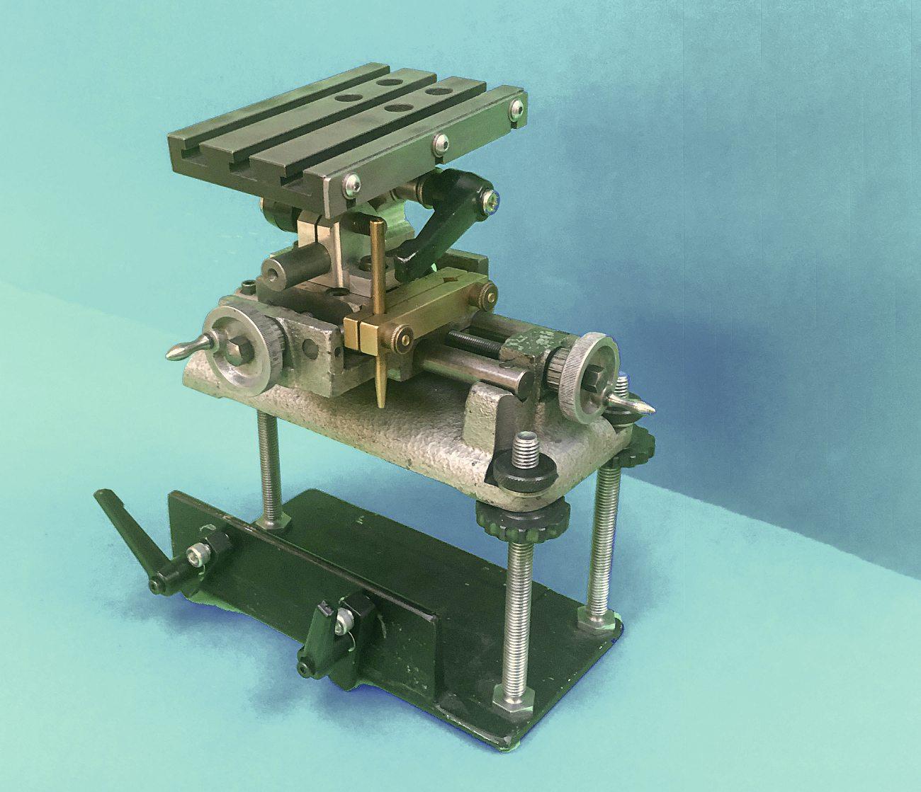
Mybenchgrinderrestutilises thecross-slidefromanearly Unimatlathe,described in MEW231.Inadditiontothe ne screwfeedstowardsandacrossthe wheelprovidedbytheslide,italso hastwoperpendiculartiltaxes,height adjustment,anditcanbepositionedin frontof,orperpendicularto,thewheel, photo1.
Likemosthomeprojects,it hascontinuedtoevolve.Major improvementsincludetheuseof indexablehandlesinsteadof xed ones,andthefabricationofanewbase toallowthetabletobeloweredfurther toaccommodatebulkytoolsheldin newly-acquiredERcollets.Thethree M10threadedpillarsthatsupport thetablehavebeenreplacedwith
longerones,andtheoriginalknurled aluminiumadjustingnutshavebeen replacedwithsteelversionswhose extrainertiaallowsthemtobespun better,tospeedupchangesintable height.Iwasafraidthatthethree pillarsmightproveinsu cientlyrigid, buttheyare ne.
Despitetheresthavingevery conceivableadjustment,Ineverfound iteasytosetthegrindingangle.O en, Iwouldwonderwhetherthetablehad tobelevel;whetheritortheedgeof thetoolshouldbeonthecentrelineof thewheel;andhowthecurvatureof thewheelcameintoit.
What nallyspurredmeontosort outmyproblemswaswhenIdecided toattempttosharpenendmills.In hisexcellentbook‘ToolandCutter Sharpening’,HaroldHalldescribes sharpeningthe utesas‘almostcertainly themostdemandingsharpeningtaskto surfaceintheaveragehomeworkshop’, soit’shardlysurprisingthatIamstill workingonthatchallenge.Butbefore that,itwasthemuchsimplertaskof sharpeningendmillteeththatreally promptedmetoseekastraightforward methodforsettingthecuttingangle. Theresultofmylaboursisshownin photo2;itconsistsofsomemodest additionstotheendshieldofthe grindingwheel,anddespiteitssimplicity, itworksverywell.
Grindingangles
Ihadalwaysbelievedthatgrinding shouldtakeplaceonornearthe horizontalcentrelineofthewheel:a er all,thatiswheretherestisprovidedon o -handgrinders,andtextsdealing withadjustablegrindingreststend toimplythatthetable(orratherthe toolbeingground)shouldinitially bealongthecentreline.Mostbooks
ModelEngineers’Workshop www.model-engineer.co.uk 14 1
ImprovedGrindingRest
recommendasetoftemplates(onefor eachclearanceangle,madefromsheet material)toaidsettingtheangle,butI preferredtogetbywiththehelpofan oldschoolprotractor,albeitwithonly moderatesuccess.

FromtimetotimeIhadsharpened largeawkwardly-shapedtoolswith therestwellabovethecentreline ontheunguardedsectionofthe wheel,withthetableangledsteeply downwards.Thiscon rmedthatthere isnothingmagicalaboutgrindingon thehorizontalcentreline:a erall, howcouldthewheelknowwhereon itsexposedperipherythecuttingwas takingplace?
Itwasuncertaintieslikethesethat promptedmetoinvestigatewhat reallymatters.My ndingsarenot new,buttheyformedthebasisforan easymethodofanglesettingwhichI hopethatothersmight nduseful.
Tokeepthingssimple,the discussionwillbelimitedtothejob ofcreatingafrontclearanceorrelief angleonarectangulartool,orthe primaryorsecondaryclearanceof endmillteeth,asthesebothrequire thesameapproach.Theangleof twentydegreeschosenforillustrative purposesislargerthanusually required,butitmakesthesketches easiertofollow.
Figure1 illustratesthesemethods. The rstapproachisshownbythe upperrowofsketches.Therestis shadedlightgreyandthetoolbitis darker.Weassumethatwestart, g. 1(a),fromapositionwherethetableis horizontal,anditsheightissuchthat
› 15 AngleSetting forBenchGrinder September2023 2
20° 10° 30° 20° 20° 20° 20° (a) (b) (c) (d) (e) (f)
Figure1.Anglesettingmethods
Aligningtherest’stableusingRulerandSectorPlate.(Thisphotoalsoshowsthe perpendicularlengthsofangleirontowhichthebaseoftherestmaybeclampedsoas tofaceeithertheedgeorthefaceofthewheel.)
thetipofthetoolisonthecentreline ofthewheel.Thisisaconvenient referencepointfromwhichtobegin ourdiscussion,thoughnotofany practicaluseasitgivesnoclearanceat thetip.
It’sperhapsworthmentioninghere thatitistheangleatthetipofthe toolthatdetermineshowwellitcuts, whichiswhywearefocusingonthe topedgeofthelathetool:thelineof cutistangentialtothewheelatthe contactpoint.
Weareaimingforanangleoftwenty degrees,sonaturallywetiltthetable upwardsbythatangleandmovethe tabletowardsthewheeluntilcontactis made,asshownin g.1(b).
Unfortunately,wecanseefrom g.1(b) thatbecausethetiltinghasraisedthe tipabovethecentreline,anadditional componentofangleisintroduced:the largertheradiusofthewheel,theless signi cantthise ectbecomes.Withthe particularproportionsshownherethe addedheightresultsinanincreaseoften degrees,sowegetaclearanceangleof thirtydegrees,notthetwentythatwe expected.
Theextratendegreesrepresents a50%errorinthe nalangleandis unlikelytobeacceptable.Butbefore wediscusswhatmustbedone,it shouldbeacknowledgedthatinorder toillustratetheprinciple,thisexample hasdeliberatelychosenalargerthan normalclearanceangle:withamore likelyangleofsay vedegrees,the ‘error’willbemuchless.
Byloweringthetableandmoving ittothele untilthetipofthetoolis againonthecentrelineofthewheel g. 1(c),thecorrectangleisobtained.
Thesecondapproachisshownin thelowerrowofsketches,inwhich g. 1(d)isthesameas g.1(a).Atwenty degree‘angleguide’asrecommendin textbooksisplacedonthetable,and amark(redin g.1(e))ismadeonthe wheelatthepointwheretheguide istangentialtothewheel.Judging thetruepointatwhichtheguideis tangentialtothewheelisnotalways easy.Thetableisthenraisedand movedhorizontallytobringthetipof thetooltotheredmark,asshownin g.1(f).
Whenwecompare gs1(c)and 1(f),weseethatif g.1(c)isrotated clockwisebytwentydegrees,it becomesidenticalto g.1(f).And ifeitherpictureweretoberotated byanyarbitraryangle,itwouldstill representanarrangementforgrinding theclearanceanglethatwewant. Thereisclearlynothingspecialabout thehorizontal,northepositionfrom whichwestart,sojustwhatdoes matter,andisthereaneasierwayof gettingtoit?
Theessentialrequirementscan bestbeseenbypicturingtwo radiallinesdrawnfromthecentre ofthewheel,andspacedapartby thedesiredclearanceangle, δ.The absoluteangularpositionofboth linesisunimportant,buttheymustbe separatedbytheangle δ.
Tosetthedesiredclearanceangle (δ),thetablemustbeparalleltooneof thelines(theblackonein fig.2);this canbeachievedeitherbyadjusting thetiltofthetabletobeparalleltothe line,ordrawingthelinesothatitis paralleltothetable,see g.2(a).Note thattheinitialpositionofthetableis unimportant,solongasitisparallelto theblackline.
Thetablemustthenbemovedto bringthetipofthetooltothepoint wherethesecond(red)lineintersects theperipheryofthewheel:grindingin thispositionwillproducethecorrect clearanceangle.
Theessentialconditionsfor achievingaspeci cangleare remarkablysimpleifweusethetwo radiallinesapproach.Thereisnothing specialabouttheangleofthetable (anditisnotevennecessaryforit tobeabletotilt),andthemethodis independentofthediameterofthe wheel.Thetablemusthoweverbe capableofverticalandhorizontal adjustment.
Atthisstage,itwouldnotsurprise meifexperiencedMEWreaderswere thinking‘sowhat-that’sobviousto me’,andtothemallIcansayisthatit certainlywasn’ttome,butI’mgladto havejoinedtheenlightenedbrethren!
Equally,therewillbethosethat thinkit’sallverywell‘picturingtwo radiallinesdrawnfromthecentreof thewheel’,butthelinesarepurely hypothetical,sohowarewetomake useofthisinpractice?
ModelEngineers’Workshop www.model-engineer.co.uk 16
δ δ
(a) (b)
Figure2.Two-linemethodforsettingclearanceangle
TheoryintoPracticeArrangementofSettingGuides
At rstIthoughtofputtinglinesonthe wheel,butthatwouldbeoflimiteduse becausethelinesneedtoprojectout asfarastherestinordertolineupthe table(or,moreimportantly,thetool). Instead,asetoflinesareengravedon asectorplate, fig.3),whichinturnis mountedonastubsha xedtothe endcoverofthegrindingwheel,and co-axialwiththewheel, photo2
Thestubsha isactuallyanM10 screw,andtheplateissecuredwith aspringwasherandnuttightened justsu cientlytoallowtheplateto


berotatedwith rmhandpressure, suchthatitremainswhereveritis positioned.
Thesectorplateismadefrom4mm acrylic,andthearrangementofnine linesde ningeightsectorsof10°was arrivedata ervarioustrialsonpieces ofcard.Thelineswereengravedwitha spotdrill,and lledwithwhitepaint. Thecentrelinebisectstheplate, whichspans90°intotal.Myeyesight isstillgoodenoughtointerpolatetoa degreeorsobetweenadjacentlinesat 10°intervals,Appendix).Ifoundthat morelinesbecametoobusy,andfewer madeinterpolationharder.
Nextonthesha comethe guideline‘ruler(s)’,madefrom transparentacrylicwithanengraved centreline.Theyaresecuredwith large,knurlednuts,andwhensetting iscompleted,theycanbeloosened tohangverticallyoutofharm’sway. Theratherclumsylookingaddition ontheright-handsideofthewheel guard(photo2)isforsettingthe rulerhorizontal:itwasaddedwhen Irealisedthatmoreo enthan notIchosetostartwiththetable horizontal.


Thetablecansetatanyarbitrary angle,butassumingthatthetableis

› 17 AngleSetting forBenchGrinder September2023
(a)
(b)
Figure3.Sectorplate
Figure4.Stagesinsettingclearanceangle
initiallytobesettothehorizontal,the procedureisasfollows,see fig.4
1)Settherulerhorizontalwiththeaid oftheguideontheright,androtatethe sectorplatesothatitsbottomedgeis horizontal,asshownin g.4(a).
2)Adjustthetiltofthetable(ormore importantlythetoolbit)sothatitis paralleltotheruler, g.4(a).


3)Rotatetherulerbytherequired clearanceangle(inthiscasetwenty

degrees,asperthepreviousexample), interpolatingbetweenthegraduations onthesectorplate,asshownin g.4(b).
4)Movethetableverticallyand horizontallyuntilthetipofthetool touchestheedgeofthewheelatthe pointindicatedbytheruler, g.4(b).
InmostcasesI ndthatonlyone rulerisneeded,butoccasionallya secondoneisuseful,especiallyifthe tableisnothorizontal.
Needlesstosayallthishastobe donebyeyeandgiventhespacing betweenthewheelandrulersitis importanttoviewthesetupalong theaxisofthewheelinordertoavoid errorsduetoparallax.
Sharpeningendmillteethisnow amuchquickerprocess.IuseHarold Hall’smethodwithaswivelbaseon thetabledesignedtorestrictgrinding tothecornerofthewheel,andI prefertosetupwiththetableslightly slopingdownwardssothatthereisno tendencyforthe xtureholdingthe toolstoslipo thetable.Sharpening theside utes–well,that’sworkstillin progress…
Appendix
Forthosewhomightbeinterested,the threesketchesin fig.5 showwhatit lookslikewhenaligningthetableand rulerbyeye.Itisnotdi culttoget withinaboutadegreeorso,whichis su cientformostpurposes,andI’m surethatfewwoulddisagreewiththe viewthatasharptoolwithaslightly wrongangleismuchbetterthana bluntonewithaperfectangle. ❚
ModelEngineers’Workshop www.model-engineer.co.uk 18 DON'TMISSTHISGREATISSUE-SEEPAGE54-55FOROURLATESTSUBSCRIPTIONOFFER
ChrisHallaway shareshis designforacompactdividing head.
GrahamMeek ‘squaresthe circle’.
NextIssue Inour Comingupinissue332, October2023 Onsale15September2023 Topre-orderyournextcopyofMEWvisit www.classicmagazines.co.ukorcall01507529529 Contentssubjecttochange 0.5° 1° 1.5°
MichaelCox convertsabasicangle viceintoatiltingmilltable.
Figure5.Degreesofmisalignment
RoundingThingsO
HowardLewisreviewshisexperiencesofusingthe‘Repton’radius turningattachment.
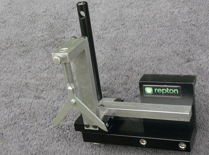

Sometimeago,afrienddiedand le measmalllegacy.Itseemed appropriatetospendthemoney onsomethingconnectedwithModel Engineering,soaReptonradiusturning attachmentwaspurchased,sinceitwas boundtobeneededatsomefuturetime. Fromtimetotime,ithas.
TheReptonradiusturning attachmentisshownin photo1. The normallystraighthandlehasbeenbent upwardstoclearthelockinghandleon thefronttoolpost.
Ifaradiusturningtoolistoproduce atrulysphericalsurface,whether convexorconcave,itneedstobeset sothatitrotatesaboutthecentre lineoftheworkpiece.Icouldnot properlyunderstandandgetonwith theinstructionsprovided,tocentre thetoolontheworkpiece.Sometimes, settingthetoolbytrialanderror methodsinboththeverticaland horizontalplanescantakelongerthan theactualturning,oncethecorrect locationshavebeenfound.
Asusual,onejobspawnsanother, andsoacenteringattachmentwas neededtosimplifymakingthatsetting. Consequently,acentringattachment wasdesignedandmadeup,touse thecenteringaidnormallyusedina drillchuckontheMill.Althoughthis examplerelatestoaReptontool, maybethedesigncanbemodi edto suitotherradiusturningattachments.
CentringTool

Thisreplacesthetoolholderinthe mainbodyofthedevice,andcarriesa commerciallyavailablecentreindicating tooltocentrethetool,ontheworkpiece, ascanbeseenin photo2. Thedevice issimplymade,consistingofpiecesof, inthiscase,aluminium, xedtogether toreplacetheactualcuttingtooland itsholder,sothattheradiusturning attachmentcanbecentredonthe workpiece,andthenthecrossslide lockedinposition
Theonlypartsrequiringanysortof precisionarethefootwhichreplaces theholderforthecuttingtoolwhile theattachmentisbeingcentredonthe workpiece.Thefootneedstobeaclose tinthegroovethroughthebaseof theattachment,ensuringthatwhen
assembled,allthepartsareatright anglestoeachother.
Theholeinthebracketwhichcarries thecentreindicatorisreamedtobeon thecentrelineofthebracket,andaclose tonthestemofthecentreindicator. Inthisinstance,forpurelycosmetic
› 19 ReptonRadius –Attachment September2023
The‘Repton’radius turningattachment
2 1
Thecentringattachment ontheRepton.
reasons,thepartsaresecuredtogether withM4buttonheadscrews,butthere isnoreasonwhyordinarycapscrews cannotbeused.


Thehorizontalbarisdeliberatelymade long,sothatitcanrestagainstthebody oftheattachmenttoensurethatthetool holdercarrierisatrightanglestotheaxis ofthelathe.
Thecrossslideandsaddlearemoved tobringthecentreindicatoroverthe materialinthechuck.Thecrossslideis thenadjusted,withthehorizontalbar heldagainstthebodyoftheattachment, untiltheindicatorshowsthattheradius turningattachmentisonthecentreline oftheworkpiece.Theattachmentbeing centredontheworkpieceisshownin
Description
Topreparetoturnaradius,the centeringdeviceisremovedfromthe body,andreplacedbythetoolholder, verylightlyclampedintoplaceandthe saddlemovedtoallowthetooltobe setagainsttheODoftheworkpiece. Thesaddleismovedawayfromthe chucksothatthetipofthetooljust touchesthecorneroftheworkpiece whenthehandleisusedtorotate thetoolaboutitspivot.Thetopslide shouldbesetasifforturningparallel tothelatheaxis.
Thehandleisusedtorotatethetool tobeginturningtheradius.Thecutis applied,usingtheTopSlidetoadvance thetool,untilthedesiredradiusor sphereisproduced.
Thedi cultbit,usually,isgaining accesstothegrubscrewsthatclamp thetoolholder rmlyintotheslotinthe mainbody,totightenthem,becauseof everythingbeingsoclosetothechuck. Oncethishasbeendone,theradius turningtoolisreadyforuse- photo4.
ModelEngineers’Workshop www.model-engineer.co.uk 20
photo3. Thecrossslideisthenlockedin place,andmustremainundisturbedwhile thetoolisused.
Centringabouttheworkpiece
3 4
Settingthetooltothe ODofthework


 NeilWyatt


